EP1275569B1 - Seat-belt guide anchor - Google Patents
Seat-belt guide anchor Download PDFInfo
- Publication number
- EP1275569B1 EP1275569B1 EP02014867A EP02014867A EP1275569B1 EP 1275569 B1 EP1275569 B1 EP 1275569B1 EP 02014867 A EP02014867 A EP 02014867A EP 02014867 A EP02014867 A EP 02014867A EP 1275569 B1 EP1275569 B1 EP 1275569B1
- Authority
- EP
- European Patent Office
- Prior art keywords
- vehicle
- seat
- belt
- front side
- seat belt
- Prior art date
- Legal status (The legal status is an assumption and is not a legal conclusion. Google has not performed a legal analysis and makes no representation as to the accuracy of the status listed.)
- Expired - Fee Related
Links
Images


Classifications
-
- B—PERFORMING OPERATIONS; TRANSPORTING
- B60—VEHICLES IN GENERAL
- B60R—VEHICLES, VEHICLE FITTINGS, OR VEHICLE PARTS, NOT OTHERWISE PROVIDED FOR
- B60R22/00—Safety belts or body harnesses in vehicles
- B60R22/18—Anchoring devices
- B60R22/24—Anchoring devices secured to the side, door, or roof of the vehicle
-
- B—PERFORMING OPERATIONS; TRANSPORTING
- B60—VEHICLES IN GENERAL
- B60R—VEHICLES, VEHICLE FITTINGS, OR VEHICLE PARTS, NOT OTHERWISE PROVIDED FOR
- B60R22/00—Safety belts or body harnesses in vehicles
- B60R22/18—Anchoring devices
- B60R2022/1818—Belt guides
-
- B—PERFORMING OPERATIONS; TRANSPORTING
- B60—VEHICLES IN GENERAL
- B60R—VEHICLES, VEHICLE FITTINGS, OR VEHICLE PARTS, NOT OTHERWISE PROVIDED FOR
- B60R22/00—Safety belts or body harnesses in vehicles
- B60R22/34—Belt retractors, e.g. reels
- B60R22/341—Belt retractors, e.g. reels comprising energy-absorbing means
Definitions
- the present invention belongs to a technical field of a seat-belt guide anchor that is swingably supported on a vehicle body, for example, a pillar, and that slidably guides a seat belt of a seat belt device in the longitudinal direction thereof.
- a seat belt device attached to the seat of a vehicle protects a passenger from injury due to a collision with a vehicle body or the like by restraining the passenger with a seat belt in case of an emergency such as a vehicle collision.
- Such a seat belt device is provided with a guide anchor that is swingably supported on the inner wall of a vehicle body, for example, a pillar, and that has a belt guide hole for slidably guiding the seat belt in the longitudinal direction thereof.
- a guide anchor that is swingably supported on the inner wall of a vehicle body, for example, a pillar, and that has a belt guide hole for slidably guiding the seat belt in the longitudinal direction thereof.
- the belt guide hole extends in the frontward and rearward direction of the vehicle.
- the guide anchor allows the seat belt to restrain the passenger in a correct position.
- a guide anchor that prevents a seat belt from being biased to one end of a belt guide hole is proposed on microfilm (hereinafter referred to as a "publication") of Japanese Unexamined Utility Model Application No. Heisei 3-96565 ( Japanese Unexamined Utility Model Application Publication No. Heisei 5-44719 ).
- GB 2 020 541 A discloses a seat belt guide anchor according to the preamble of claim 1 and 3.
- multiple seat belt devices have been developed in which, in case of an emergency, such as a vehicle collision, a pretensioner is actuated to drive a retractor in the seat-belt winding direction and to thereby wind the seat belt, thereby increasing the force of the seat belt for restraining the passenger. Since the seat belt is also rapidly wound in such winding of the seat belt by the retractor in response to the actuation of the pretensioner, the above-described biasing of the seat belt also sometimes occur. Accordingly, it is possible to prevent the seat belt from being biased from the actuation of the pretensioner by using the guide anchor disclosed in the above publication.
- the seat belt when the pretensioner is actuated, the seat belt is wound far more rapidly than disclosed in the above publication. For this reason, it is difficult for the projections or recesses oriented in the seat-belt traveling direction, as disclosed in the above publication, to effectively prevent the seat belt from being biased. Even when the guide anchor in the publication is used, the seat belt may be biased.
- EA mechanism an energy absorption mechanism
- the drawing of the seat belt is locked by a retractor in case of an emergency, such as a vehicle collision.
- Energy absorption by the EA mechanism is performed by twisting a torsion bar provided in the retractor. In this case, the seat belt is drawn from the retractor by an amount corresponding to the twisting of the torsion bar.
- the seat belt When the seat belt is thus drawn in response to the actuation of the EA mechanism, since it is also drawn far more rapidly than in normal drawing operation, the above-described biasing of the seat belt may occur similarly. Accordingly, it is possible to prevent the seat belt from being biased from the actuation of the EA mechanism by using the guide anchor disclosed in the above publication, in a manner similar to that in the above case in which the pretensioner is actuated.
- the present invention has been made in view of such circumstances, and an object of the invention is to provide a seat-belt guide anchor that can more effectively and more reliably prevent a seat belt from being biased when the seat belt is rapidly drawn and is rapidly wound in case of an emergency such as a vehicle collision.
- a seat-belt guide anchor as claimed in claim 1 provides a seat-belt guide anchor that is swingably supported on a vehicle body, such as a pillar, and that guides a seat belt while the seat belt travels through a belt guide hole so as to slide in the longitudinal direction thereof, wherein a projection or a recess is formed in a sliding portion for the seat belt, a vehicle-rear side end of the projection or a vehicle-rear side end of the sliding portion forming the recess is inclined with respect to an orthogonal direction orthogonal to the belt guide hole disposed in the sliding portion for the seat belt in a state in which the seat-belt guide anchor is mounted on the vehicle body, and the angle of the inclination is set to be more than the inclination angle of the traveling direction of the seat belt through the belt guide hole with respect to the orthogonal direction.
- a seat-belt guide anchor as claimed in claim 2 provides a seat-belt guide anchor that is swingably supported on a vehicle body, such as a pillar, and that guides a seat belt while the seat belt travels through a belt guide hole so as to slide in the longitudinal direction thereof, wherein a projection or a recess is formed in a sliding portion for the seat belt, a vehicle-rear side end of the projection or a vehicle-rear side end of the sliding portion forming the recess is inclined with respect to an orthogonal direction orthogonal to the belt guide hole disposed in the sliding portion for the seat belt in a state in which the seat-belt guide anchor is mounted on the vehicle body, and the angle of the inclination is set to be less than the inclination direction of the traveling direction of the seat belt through the belt guide hole with respect to the orthogonal direction, or the direction of the inclination is opposite with respect to the orthogonal direction.
- the projection is shaped like a rib, or the recess is shaped like a concave groove.
- a seat-belt guide anchor as claimed in claim 4 provides a seat-belt guide anchor that is swingably supported on a vehicle body, such as a pillar, and that guides a seat belt while the seat belt travels through a belt guide hole so as to slide in the longitudinal direction thereof, wherein multiple projections or multiple recesses are formed in a sliding portion for the seat belt, vehicle-rear side ends of the multiple projections or vehicle-rear side ends of the recesses include a first vehicle-rear side end and a second vehicle-rear side end in a state in which the seat-belt guide anchor is mounted on the vehicle body, the first vehicle-rear side end is inclined with respect to an orthogonal direction orthogonal to the belt guide hole disposed in the sliding portion for the seat belt, the angle of the inclination is set to be more than the inclination angle of the traveling direction of the seat belt through the belt guide hole with respect to the orthogonal direction, the second vehicle-rear side end is inclined with respect to the orthogonal direction orthogonal to the belt
- the vehicle-rear side end of the projection or the vehicle-rear side end of the sliding portion forming the recess is formed of a round portion having a minute diameter or of an edge portion.
- a vehicle-front side end of the projection or a vehicle-front side end of the sliding portion forming the recess is formed of a round portion having a large diameter or of a chamfered portion.
- a vehicle-front side end of the projection or a vehicle-front side end of the sliding portion forming the recess extends in the traveling direction of the seat belt through the belt guide hole.
- a vehicle-front side end of the projection or a vehicle-front side end of the sliding portion forming the recess is formed in a stepped shape by a predetermined number of combinations of first vehicle-front side end portions parallel to the traveling direction of the seat belt through the belt guide hole, and second vehicle-front side end portions perpendicular to the first vehicle-front side end portions.
- the seat-belt guide anchor as claimed in claim 1 having such a configuration, when the seat belt is rapidly wound, for example, in response to the actuation of a pretensioner in case of an emergency such as a vehicle collision, the movement of the seat belt toward the vehicle front side is inhibited by the vehicle-rear side end of the projection or the vehicle-rear side end of the seat-belt sliding portion forming the recess. This makes it possible to more effectively and more reliably prevent the seat belt from being biased toward the vehicle front side.
- the seat-belt guide anchor as claimed in claim 1 is suitable particularly for a seat belt device having a pretensioner.
- the seat-belt guide anchor as claimed in claim 2 when the seat belt is drawn while absorbing impact energy, for example, in response to the actuation of an EA mechanism in case of an emergency such as a vehicle collision, the movement of the seat belt toward the vehicle front side is inhibited by the vehicle-rear side end of the projection or the vehicle-rear side end of the seat-belt sliding portion forming the recess. This makes it possible to more effectively and more reliably prevent the seat belt from being biased toward the vehicle front side.
- the seat-belt guide anchor as claimed in claim 2 is suitable particularly for a seat belt device that does not have a pretensioner, but has an EA mechanism.
- the projection is shaped like a rib or the recess is shaped like a concave groove, the structure is simplified, and production is facilitated.
- the seat-belt guide anchor as claimed in claim 4, when the seat belt is rapidly wound, for example, in response to the actuation of a pretensioner in case of an emergency such as a vehicle collision, the movement of the seat belt toward the vehicle front side is inhibited by the first vehicle-rear side ends of the projections or the first vehicle-rear side ends of the seat-belt sliding portion forming the recesses.
- the seat-belt guide anchor as claimed in claim 4 is suitable particularly for a seat belt device that has at least one of a pretensioner and an EA mechanism.
- the vehicle-rear side end of the projection or the vehicle-rear side end of the sliding portion forming the recess is formed of a round portion having a minute diameter or of an edge portion, the movement of the seat belt toward the vehicle front side is more effectively inhibited by a reactive force produced from the vehicle-rear side end by the friction between the vehicle-rear side end and the seat belt.
- the vehicle-front side end of the projection or the vehicle-front side end of the sliding portion forming the recess is formed of a round portion having a large diameter or of a chamfered portion, little friction occurs between the vehicle-front side end and the seat belt, and the movement of the seat belt toward the vehicle front side due to the vehicle-front side end is inhibited.
- the vehicle-front side end of the projection or the vehicle-front side end of the sliding portion forming the recess extends in the traveling direction of the seat belt through the belt guide hole, little friction occurs between the vehicle-front side end and the seat belt, and the movement of the seat belt toward the vehicle front side due to the vehicle-front side end is inhibited.
- the vehicle-front side end of the projection or the vehicle-front side end of the sliding portion forming the recess is formed in a stepped shape by a predetermined number of combinations of first vehicle-front side end portions parallel to the traveling direction of the seat belt through the belt guide hole and second vehicle-front side end portions perpendicular to the first vehicle-front side end portions, a force for moving the seat belt toward the vehicle front side is not produced by the vehicle-front side end. Therefore, when the seat belt is drawn, the turning of the guide anchor is inhibited, and the movement of the seat belt toward the vehicle front side is inhibited.
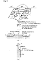
- Figs. 1(a), 1(b), and 1(c) show a seat-belt guide anchor according to a first embodiment of the present invention
- Fig. 1(a) is a view of the guide anchor of the first embodiment
- Fig. 1(b) is a partially enlarged view of a section IB in Fig. 1(a)
- Fig. 1(c) is a partially enlarged view, similar to Fig. 1(b) , showing a modification of a section IB.
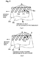
- Figs. 2(a) and 2(b) show the operation of the guide anchor of the first embodiment
- Fig. 2(a) is an explanatory view showing an operating state of a pretensioner
- Fig. 2(b) is an explanatory view showing an operating state of the pretensioner.
- Fig. 3 is a view of a guide anchor according to a second embodiment of the present invention, in a manner similar to that in Fig. 1(a) .
- Figs. 4(a) and 4(b) show a guide anchor according to a third embodiment of the present invention
- Fig. 4(a) is a partial view of the guide anchor shown in a manner similar to that in Fig. 1(a)
- Fig. 4(b) is a partially enlarged view of a section IVB in Fig. 4(b) .
- Fig. 5 is a partial view of a guide anchor according to a fourth embodiment of the present invention, in a manner similar to that in Fig. 4(a) .
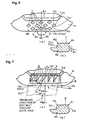
- Figs. 6(a) and 6(b) show a guide anchor according to a fifth embodiment of the present invention
- Fig. 6(a) is a partial view similar to Fig. 4(a)
- Fig. 6(b) is a partially enlarged sectional view, taken along lines VIB 1 -VIB 1 and VIB 2 -VIB 2 in Fig. 6(a) .
- Figs. 7(a) and 7(b) show a guide anchor according to a sixth embodiment of the present invention
- Fig. 7(a) is a partial view similar to Fig. 4(a)
- Fig. 7(b) is a partially enlarged sectional view, taken along lines VIIB-VIIB in Fig. 7(a) .
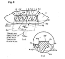
- Figs. 8(a) and 8(b) show a guide anchor according to a seventh embodiment of the present invention
- Fig. 8(a) is a partial view similar to Fig. 4(a)
- Fig. 8(b) is a partially enlarged view of a section VIIIB in Fig. 8(a) .
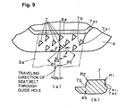
- Figs. 9(a) and 9(b) show a guide anchor according to an eighth embodiment of the present invention
- Fig. 9(a) is a partial view similar to Fig. 4(a)
- Fig. 9(b) is a partially enlarged sectional view, taken along lines IXB1-IXB12 and IXB2-IXB12 in Fig. 9(a) .
- Figs. 10(a), 10(b), and 10(c) show a guide anchor according to a ninth embodiment of the present invention
- Fig. 10(a) is a partial view similar to Fig. 4(a)
- Fig. 10(b) is a partially enlarged sectional view, taken along line XB-XB in Fig. 10(a)
- Fig. 10(c) is a partially enlarged sectional view, taken along line XC-XC in Fig. 10(a) .
- Figs. 11(a), 11(b), and 11(c) show a guide anchor according to a tenth embodiment of the present invention
- Fig. 11(a) is a partial view similar to Fig. 4(a)
- Fig. 11(b) is a partially enlarged sectional view, taken along line XIB-XIB in Fig. 11(a)
- Fig. 11(c) is a partially enlarged sectional view, taken along line XIC-XIC in Fig. 11(a) .
- Fig. 12 is an explanatory view showing the operation of a conventional seat-belt guide anchor.
- Figs. 1(a) and 1(b) show a seat-belt guide anchor according to a first embodiment of the present invention
- Fig. 1(a) is a view of the guide anchor of the first embodiment
- Fig. 1(b) is a partially enlarged view of a section IB in Fig. 1(a) .
- a seat-belt guide anchor 1 of the first embodiment comprises a mounting section 2 having a mounting hole 2a through which a fastener, such as a bolt, for swingably mounting the guide anchor 1 to a vehicle body, and a belt guide section 4 having a belt guide hole 4a for guiding a seat belt 3 that is slidably passed therethrough.
- the mounting section 2 and the belt guide section 4 are formed by bending so that they are at a predetermined angle to each other.
- the guide anchor 1 may be made of only resin, may be formed by attaching a belt guide section 4 separately made of resin or metal as a strength member and molded together, or may be made of only metal.
- a predetermined number of (ten in the illustration) ribs (corresponding to projections in the present invention) 5 of a fixed width are formed on a sliding portion 4b for the seat belt 3 in the belt guide section 4 including the belt guide hole 4a.
- These ribs 5 are continuously formed from a sliding portion 4b 1 in which a passenger-side portion of the seat belt 3 slides (front side in the figure) to a sliding portion 4b 2 in which a retractor-side portion of the seat belt 3 slides (rear side in the figure) (the ribs 5 at the right and left ends are not always formed on both sides 4b 1 and 4b 2 of the sliding portion 4b outside a sliding area of the seat belt 3).
- each of the ribs 5 a portion thereof in the sliding portion 4b 1 (a portion shown by a solid line in the figure) extends toward the vehicle front side so as to be inclined downward, and a portion thereof in the sliding portion 4b 2 (a portion shown by a dotted line in the figure) extends toward the vehicle rear side so as to be inclined downward.
- the guide anchor 1 of the first embodiment is adapted particularly to a seat belt device in which a retractor winds up the seat belt 3 by a predetermined amount in response to the actuation of a pretensioner in the above-described case of an emergency.
- the guide anchor 1 of the first embodiment is also suitable for such a seat belt device.
- the guide anchor 1 of the first embodiment is, of course, also suitable for a seat belt device that does not have a pretensioner and an EA mechanism.
- the inclination angle ⁇ 1 of each of the ribs 5 formed in the sliding portion 4b 1 with respect to the upward and downward direction in Fig. 1(a) is set to be a predetermined angle larger than the inclination angle ⁇ b of the traveling direction the passenger-side portion 3a of the seat belt 3 through the belt guide hole 4a (shown by a solid arrow in the figure) with respect to the upward and downward direction in the figure (the inclination angle of the longitudinal direction of the passenger-side portion 3a of the seat belt 3 with respect to the upward and downward in the figure).
- the inclination angle ⁇ b also corresponds to the inclination angle of the direction of drawing of the seat belt 3 by the EA operation.
- the inclination angle ⁇ 1 of each of the ribs 5 formed in the sliding portion 4b 2 with respect to the upward and downward direction in Fig. 1(a) is set to be a predetermined angle larger than the inclination angle ⁇ b of the traveling direction the retractor-side portion 3b of the seat belt 3 through the belt guide hole 4a (shown by a dotted arrow in the figure) with respect to the upward and downward direction in the figure (the inclination angle of the longitudinal direction of the retractor-side portion 3b of the seat belt 3 with respect to the upward and downward in the figure).
- Both the angles ⁇ 1 and ⁇ b are expressed in the absolute value. This also applies to all the angles that will be described in the following other embodiments.
- the predetermined angle is set at an angle such that a force F 1 which the passenger-side portion 3a of the seat belt 3 exerts on vehicle-rear side ends 5a of the ribs 5 is produced by the friction between the passenger-side portion 3a of the seat belt 3 and the vehicle-rear side ends 5a of the ribs 5a when the seat belt is wound by the actuation of the pretensioner, and such that a reactive force F2 is produced which acts on the passenger-side portion 3a of the seat belt 3 so as not to move the seat belt 3 to the vehicle front side (leftward in the figure), as shown in Fig. 2(a) .
- This also applies to the sliding portion 4b 2 .
- the arrows of the forces F 1 and F 2 represent only the directions of the forces F 1 and F 2 , and do not represent the magnitudes of the forces F 1 and F 2 .
- the vehicle-rear side end 5a of the rib 5 is formed of a round portion having a minute diameter R 1 , or of an edge portion (cusp).
- the minute diameter R 1 is determined so that the above-described reactive force F 2 , which has a magnitude such as not to move the seat belt 3 to the vehicle front side, reliably acts on the seat belt 3.
- a vehicle-front side end 5b of the rib 5 is formed of a round portion having a relatively large diameter R 2 .
- the vehicle-front side end 5b of the rib 5 may be formed of a chamfered portion chamfered along the sides x and y, instead of the round portion having a relatively large diameter R 2 .
- the large diameter R 2 or the chamfering is determined so that little friction occurs between the seat belt 3 and the vehicle-front side end 5b of the rib 5 when the belt is drawn in response to the above-described actuation of the EA mechanism, as shown in Fig.
- the side y be set to be longer than the side x. While the chamfered portion shown in Fig. 1(c) is formed so that the vehicle-front side end 5b does not remain, it may be formed so that a part of the vehicle-front side end 5b remains.
- the seat belt 3 is inhibited by the above reactive force F 2 from the ribs 5 from moving toward the vehicle-front side end of the guide hole 4a. This makes it possible to more effectively and more reliably prevent the seat belt 3 from being biased to the vehicle front side when being rapidly wound by the activation of the pretensioner.
- the retractor has an EA mechanism
- little friction is produced between the seat belt 3 and the vehicle-front side ends 5b of the ribs 5 when the seat belt 3 is drawn during the operation of the EA mechanism in the above case of an emergency, and little reactive force to the force F 3 which the seat belt 3 exerts on the vehicle-front side ends 5b of the ribs 5 is produced by the friction, as described above. Therefore, even when the ribs 5 are formed, the force for moving the seat belt 3 toward the vehicle front side is hardly produced from the ribs 5, the seat belt 3 is smoothly drawn by the actuation of the EA mechanism of the seat belt 3, and more reliable energy absorption is possible.
- Fig. 3 is a view, similar to Fig. 1(a) , showing a guide anchor according to a second embodiment of the present invention.
- ribs 5 are formed in line symmetry with the ribs 5 of the guide anchor 1 of the above first embodiment in the upward and downward direction in the figure so that they are inclined in the direction opposite from that in the first embodiment. That is, in the second embodiment, the inclination angle ⁇ 2 of the ribs 5 with respect to the upward and downward direction in the figure is set to be equal to the inclination angle ⁇ 1 of the ribs 5 in the above first embodiment.
- the inclination angle ⁇ 2 of the ribs 5 in the second embodiment may, of course, be set to be different from the inclination angle ⁇ 1 of the ribs 5 in the above first embodiment.
- the guide anchor 1 of the second embodiment is adapted particularly to a seat belt device which does not have a pretensioner and in which a seat belt 3 is drawn by a predetermined amount by EA operation of an EA mechanism in the above case of an emergency.
- the guide anchor 1 of the second embodiment is, of course, also suitable for a seat belt device that does not have a pretensioner and an EA mechanism.
- the seat belt 3 when the seat belt 3 is drawn during the EA operation, it exerts a force (corresponding to the above-described force F 1 ) on vehicle-rear side ends 5a of the ribs 5 due to the friction between the vehicle-rear side ends 5a of the ribs 5, in a manner similar to that in the case in which the pretensioner is actuated in the above first embodiment, and a reactive force thereto (corresponding to the above-described reactive force F 2 ) prevents the seat belt 3 from moving toward the vehicle front side.
- a force corresponding to the above-described force F 1
- the seat belt 3 exerts little force (corresponding to the above-described force F 3 ) on the vehicle-rear side ends 5a of the ribs 5 due to the friction, and a reactive force thereto (corresponding to the above-described reactive force F 4 ), that is, the force for moving the seat belt 3 toward the vehicle front side, is not produced.
- the ribs 5 in the second embodiment need not be always inclined in line symmetry with and in the direction opposite from the first embodiment, and it is satisfactory as long as the extending direction of the ribs 5 formed in a sliding portion 4b 1 is shifted counterclockwise by a predetermined angle from the traveling direction of the seat belt 3 through the belt guide hole. That is, it is satisfactory as long as the inclination angle of the vehicle-rear side ends 5a of the ribs 5 is set to be smaller than the inclination angle ⁇ b of the traveling direction of the seat belt 3 through belt guide hole with respect to the upward and downward direction in the figure, or as long as the direction of the inclination with respect to the upward and downward direction is opposite.
- the traveling direction of the seat belt 3 through the belt guide hole is different from the belt traveling direction when the pretensioner is actuated in the first embodiment, but is the same as the direction of drawing of the seat belt 3 by the EA operation.
- Figs. 4(a) and 4(b) show a guide anchor according to a third embodiment of the present invention
- Fig. 4(a) is a partial view of the guide anchor shown in a manner similar to that in Fig. 1(a)
- Fig. 4(b) is a partially enlarged view of a section IVB in Fig. 4(a) .
- a seat-belt sliding portion 4b is provided with a predetermined number of concave grooves (corresponding to the recesses in the present invention) 6 that are inclined in a manner similar to that of the ribs 5 in the above first embodiment, instead of the ribs 5.
- vehicle-rear side ends 4b' a of seat-belt sliding portions 4b' forming the concave grooves 6 are formed of a round portion having a minute diameter R 1 or of an edge portion, in a manner similar to that of the vehicle-rear side ends 5a of the ribs 5 in the above first embodiment.
- Vehicle-front side ends 4b' b of the seat-belt sliding portions 4b' forming the concave grooves 6 are formed of a round portion having a large diameter R 2 in a manner similar to that of the vehicle-front side ends 5b of the ribs 5 in the above first embodiment, or of a chamfered portion (not shown) similar to that in the first embodiment.
- the seat-belt sliding portion 4b' that forms the concave grooves 6 serves the same functions as those of the ribs 5 in the first embodiment.
- the guide anchor 1 of the third embodiment also provides advantages similar to those of the first embodiment.
- the guide anchor 1 of the third embodiment is suitable particularly for a seat belt device in which a seat belt is wound by a pretensioner, in a manner similar to that in the first embodiment.
- a seat belt device that does not have a pretensioner, but has an EA mechanism, the inclination direction of the concave grooves 6 is made opposite from that in the third embodiment, in a manner similar to that in the above second embodiment shown in Fig. 3 .
- Fig. 5 is a partial view, similar to Fig. 4(a) , showing a guide anchor according to a fourth embodiment of the present invention.
- a smaller number of ribs 5 than the ribs 5 in the above first embodiment are formed in a seat-belt sliding portion 4b.
- the interval between the ribs 5 is set to be larger than that of the ribs 5 in the first embodiment.
- the guide anchor 1 of the fourth embodiment is suitable particularly for a seat belt device in which a seat belt is wound by a pretensioner, in a manner similar to that in the guide anchor 1 of the first embodiment.
- a seat belt device that does not have a pretensioner, but has an EA mechanism, the inclination direction of the ribs 5 is made opposite from that in the first embodiment, in a manner similar to that in the above second embodiment shown in Fig. 3 .
- Figs. 6(a) and 6(b) show a guide anchor according to a fifth embodiment of the present invention
- Fig. 6(a) is a partial view similar to Fig. 4(a)
- Fig. 6(b) is a partially enlarged sectional view, taken along lines VIB 1 -VIB 1 and VIB 2 -VIB 2 in Fig. 6(a) .
- a seat-belt sliding portion 4b is provided with a predetermined number of parallelogrammatic projections (corresponding to the projections in the present invention) 7 formed of overlapping portions of the ribs 5 of the first embodiment shown in Fig. 1(a) and the ribs 5 of the second embodiment shown in Fig. 3 (the inclination angle ⁇ 1 ⁇ the inclination angle ⁇ 2 in this case).
- the projections 7 are rhombic.
- vehicle-rear side ends 7a 1 and 7a 2 of the projections 7 in the fifth embodiment are both formed of a round portion having a minute diameter R 1 or of an edge portion, in a manner similar to that in the first embodiment, and vehicle-front side ends 7b 1 and 7b 2 of the projections 7 are both formed of a round portion having a large diameter R 2 in a manner similar to that in the above first embodiment, or of a chamfered portion similar to that in the first embodiment.
- the vehicle-rear side ends 7a 1 have operation-effects substantially similar to those of the vehicle-rear side ends 5a 1 in the first embodiment, and the vehicle-rear side ends 7a 2 have operation-effects substantially similar to those of the vehicle-rear side ends 5a 1 in the second embodiment.
- the vehicle-front side ends 7b 1 have operation-effects substantially similar to those of the vehicle-front side ends 5b 1 in the first embodiment, and the vehicle-front side ends 7b 2 have operation-effects substantially similar to those of the vehicle-front side ends 5b 1 in the second embodiment. While the projections 7 are formed on the front side of the sliding portion 4b of the seat belt 3 in Fig. 6(a) , projections 7 are, of course, also formed on the rear side of the sliding portion 4b of the seat belt 3.
- the guide anchor 1 of the fifth embodiment is suitable particularly for a seat belt device that has at least one of a pretensioner and an EA mechanism.
- Other operation-effects of the guide anchor 1 of the fifth embodiment are similar to those in the first embodiment and the second embodiment.
- parallelogrammatic recesses having a shape similar to that of the projections 7 may be arranged with the projections 7, in a manner similar to that in the concave grooves of the third embodiment.
- each side of the parallelogrammatic projections 7 needs to be made relatively long in order to more effectively prevent the seat belt 3 from being biased.
- the vehicle-rear side ends of the sliding portions 4b forming the recesses are formed of a round portion having a minute diameter R 1 or of an edge portion, and the vehicle-front side ends of the sliding portions 4b forming the recesses are formed of a round portion having a large diameter R 2 , in a manner similar to that in the concave grooves of the third embodiment.
- Figs. 7(a) and 7(b) show a guide anchor according to a sixth embodiment of the present invention
- Fig. 7(a) is a partial view similar to Fig. 4(a)
- Fig. 7(b) is a partially enlarged sectional view, taken along line VIIB-VIIB in Fig. 7(a) .
- a guide piece 8 having ribs 5 and made of, for example, Cr is mounted on a belt sliding portion 4b.
- the inclination angle ⁇ 1 of vehicle-rear side ends 5a of the ribs 5 in the sixth embodiment shown in Fig. 7(a) is set to be larger than the inclination angle ⁇ b of the traveling direction of the seat belt 3 through the belt guide hole, that is, the direction of drawing of the seat belt 3 by the EA operation, in a manner similar to that in the first embodiment.
- all the vehicle-rear side ends 5a of the ribs 5 in the sixth embodiment are formed of a round portion having a minute diameter R 1 or of an edge portion, in a manner similar to that in the above first embodiment, and all the vehicle-front side ends 5b of the projections 5 are formed of a round portion having a large diameter R 2 or of a chamfered portion, in a manner similar to that in the above first embodiment.
- the vehicle-rear side ends 5a have operation-effects substantially similar to those of the vehicle-rear side ends 5a in the first embodiment.
- a reactive force for moving the seat belt 3 toward the vehicle front side does not act from the vehicle-front side ends 5b onto the seat belt 3 when the seat belt 3 is drawn during the operation of the EA mechanism. Moreover, a reactive force for moving the seat belt 3 toward the vehicle front side does not act because of the round portion having a large diameter R 2 , in a manner similar to that in the above first embodiment.
- the round portions at the vehicle-front side ends 5b may be formed of a round portion having a minute diameter R 1 or of an edge portion, depending on the circumstances.
- the guide anchor 1 of the sixth embodiment is suitable particularly for a seat belt device having a pretensioner, in a manner similar to that in the first embodiment.
- Figs. 8(a) and 8(b) show a guide anchor according to a seventh embodiment of the present invention
- Fig. 8(a) is a partial view similar to Fig. 4(a)
- Fig. 8(b) is a partially enlarged view of a section VIIIB in Fig. 8(a) .
- the inclination angle ⁇ 1 of vehicle-rear side ends 4b' a of seat-belt sliding portions 4b' forming the concave grooves 6 with respect to the upward and downward direction in the figure is set to be larger than the inclination angle ⁇ b of the traveling direction of a seat belt 3.
- the vehicle-rear side ends 4b' a of the seat-belt sliding portions 4b' forming the concave grooves 6 are formed of a round portion having a minute diameter R 1 or of an edge portion, in a manner similar to that of the vehicle-rear side ends 5a of the ribs 5 in the above first embodiment.
- the vehicle-front side ends 4b' b of the seat-belt sliding portions 4b' forming the concave grooves 6 are formed of a round portion having a large diameter R 2 in a similar to that of the vehicle-front side ends 5b of the ribs 5 in the above first embodiment, or of a chamfered portion similar to that in the first embodiment.
- Figs. 9(a) and 9(b) show a guide anchor according to an eighth embodiment of the present invention
- Fig. 9(a) is a partial view similar to Fig. 4(a)
- Fig. 9(b) is a partially enlarged view, taken along lines IXBI-IXB12 and IXB2-IXB12 in Fig. 9(a) .
- projections 7 of the guide anchor 1 of the above fifth embodiment shown in Fig. 6(a) are shaped like a parallelogram
- projections 7 in a guide anchor 1 of the eighth embodiment are shaped like a triangle, as shown in Fig. 9(a) .
- vehicle-rear side ends 7a 1 and 7a 2 of the projections 7 in the eighth embodiment are similar to the vehicle-rear side ends 7a 1 and 7a 2 in the above fifth embodiment
- vehicle-front side ends 7b of the projections 7 in the eighth embodiment are similar to the vehicle-front side ends 7b of the above sixth embodiment shown in Fig. 7(a) .
- the vehicle-rear side ends 7a 1 and 7a 2 of the projections 7 are formed of a round portion having a minute diameter R 1 or of an edge portion, in a manner similar to that in the above first embodiment, and the vehicle-front side ends 7b of the projections 7 are formed of a round portion having a large diameter R 2 in a manner similar to that in the above first embodiment, or of a chamfered portion similar to that in the first embodiment.
- the vehicle-rear side ends 7a 1 have operation-effects substantially similar to those of the vehicle-rear side ends 5a 1 in the first embodiment
- the vehicle-rear side ends 7a 2 have operation-effects substantially similar to those of the vehicle-rear side ends 5a 1 in the second embodiment
- the vehicle-front side ends 7b have operation-effects substantially similar to those of the vehicle-front side ends 5b in the sixth embodiment.
- Fig. 9(a) shows that the projections 7 are formed on the front side of a sliding portion 4b for a seat belt 3
- projections 7 are, of course, also formed on the rear side of the sliding portion 4b for the seat belt 3.
- the guide anchor 1 of the eighth embodiment is suitable for a seat belt device that has at least one of a pretensioner and an EA mechanism.
- Figs. 10(a), 10(b), and 10(c) show a guide anchor according to a ninth embodiment of the present invention
- Fig. 10(a) is a partial view similar to Figs. 2(a) and 2(b)
- Fig. 10(b) is a partially enlarged sectional view, taken along line XB-XB in Fig. 10(a)
- Fig. 10(c) is a partially enlarged sectional view, taken along line XC-XC in Fig. 10(a) .
- vehicle-front side ends 5b of the ribs 5 are linearly formed in the sixth embodiment shown in Fig. 7
- vehicle-front side ends 5b of ribs 5 in a guide anchor 1 of the ninth embodiment are formed in a stepped shape by a predetermined number of combinations of first vehicle-front side end portions 5b 1 having the same inclination angle ⁇ 3 as that of the vehicle-front side ends 5b of the sixth embodiment and second vehicle-front side end portions 5b 2 disposed at right angles to the first vehicle-front side end portions 5b 1 , as shown in Fig. 10(a) .
- the direction of drawing of the seat belt 3 by the operation of the EA mechanism and the first vehicle-front side end portions 5b 1 are in parallel with each other, and the direction of drawing of the seat belt 3 by the operation of the EA mechanism and the second vehicle-front side end portions 5b 2 are at right angles to each other.
- the first and second vehicle-front side end portions 5b 1 and 5b 2 are chamfered, in a manner similar to that in the embodiment shown in Fig. 1(c) , and the corners of the chamfers are round.
- a reactive force F 4 that moves the seat belt 3 toward the vehicle front side does not act from the vehicle-front side ends 5b onto the seat belt 3, and a reactive force that moves the seat belt 3 toward the vehicle front side does not act because of the chamfered and round portions, in a manner similar to that in the above first embodiment.
- the seat belt 3 exerts a force F 3 on the vehicle-front side ends 5b of the ribs 5, since the direction of drawing of the seat belt 3 by the operation of the EA mechanism and the first vehicle-front side end portions 5b 1 are in parallel with each other, and the belt drawing direction and the second vehicle-front side end portions 5b 2 are at right angles to each other, a component orthogonal to the first vehicle-front side end portions 5b1 is not produced in the force F 3 . That is, a force for turning the guide anchor is not produced by the force F 3 , or a little force is produced by the force F 3 . Consequently, the guide anchor will not turn.
- the vehicle-front side ends 5b in the guide anchor 1 of the ninth embodiment may be provided with a large diameter R2, as shown in Fig. 1(b) , instead of being chamfered. While the vehicle-front side ends 5b need not always be chamfered or have a large diameter R2 in the ninth embodiment, it is preferable to provide such chamfering or a large diameter R2 in order to reliably achieve the above desired operation-effects.
- the guide anchor 1 of the ninth embodiment is suitable particularly for a seat belt device having a pretensioner, in a manner similar to that in the sixth embodiment.
- Figs. 11(a), 11(b), and 11(c) show a guide anchor according to a tenth embodiment of the present invention
- Fig. 11(a) is a partial view similar to Figs. 2(a) and 2(b)
- Fig. 11(b) is a partially enlarged sectional view, taken along line XIB-XIB in Fig. 11(a)
- Fig. 11(c) is a partially enlarged sectional view, taken along line XIC-XIC in Fig. 11(a) .
- vehicle-front side ends 4b' b of the concave grooves 6 are linearly formed in the seventh embodiment shown in Fig. 8
- vehicle-front side ends 4b' b of concave grooves 6 in a guide anchor 1 of the tenth embodiment are formed in a stepped shape by a predetermined number of combinations first vehicle-front side end portions 4b' b1 having the same inclination angle ⁇ 3 as that of the vehicle-front side ends 4b' b of the eighth embodiment and second vehicle-front side end portions 4b' b2 disposed at right angles to the first vehicle-front side end portions 4b' b1 , as shown in Fig. 11(a) .
- the direction of drawing of the seat belt 3 by the actuation of the EA mechanism and the first vehicle-front side end portions 4b' b1 are in parallel with each other, and the direction of drawing of the seat belt 3 by the actuation of the EA mechanism and the second vehicle-front side end portions 4b b2 are at right angles to each other.
- the first and second vehicle-front side end portions 4b' b1 and 4b' b2 are chamfered, in a manner similar to that in the embodiment shown in Fig. 1(c) , and the corners of the chamfers are round.
- a reactive force F 4 that moves the seat belt 3 toward the vehicle front side does not act from the vehicle-front side ends 4b' b onto the seat belt 3, and a reactive force that moves the seat belt 3 toward the vehicle front side does not act because of the chamfered and round portions, in a manner similar to that in the above first embodiment.
- the seat belt 3 exerts a force F 3 on the vehicle-front side ends 4b' b of the concave grooves 6, since the direction of drawing of the seat belt 3 by the actuation of the EA mechanism and the first vehicle-front side end portions 4b' b1 are in parallel with each other, and the belt drawing direction and the second vehicle-front side end portions 4b' b2 are at right angles to each other, a component orthogonal to the first vehicle-front side end portions 4b' b1 is not produced in the force F 3 . That is, a force for turning the guide anchor is not produced by the force F 3 , or a little force is produced by the force F 3 . Consequently, the guide anchor will not turn.
- the vehicle-front side ends 4b' b in the guide anchor 1 of the tenth embodiment may be provided with a large diameter R2, as shown in Fig. 1(b) , instead of being chamfered. While the vehicle-front side end portions 4b' b need not always be chamfered or have a large diameter R2 in the tenth embodiment, it is preferable to provide such chamfering or a large diameter R2 in order to reliably achieve the above desired operation-effects.
- the guide anchor 1 of the tenth embodiment is suitable particularly for a seat belt device having a pretensioner, in a manner similar to that in the eighth embodiment.
- the seat-belt guide anchor of the invention as claimed in claim 1 when the seat belt is rapidly wound, for example, in response to the actuation of a pretensioner in case of an emergency such as a vehicle collision, the movement of the seat belt toward the vehicle front side is inhibited by the vehicle-rear side end of the projection or the vehicle-rear side end of the seat-belt sliding portion forming the recess.
- the seat-belt guide anchor as claimed in claim 1 can optimally prevent a seat belt from being biased in a seat-belt guide anchor of a seat belt device having a pretensioner.
- the seat-belt guide anchor as claimed in claim 1 when the seat belt is drawn while absorbing impact energy, for example, in response to the actuation of an EA mechanism in case of an emergency such as a vehicle collision, the movement of the seat belt toward the vehicle front side is inhibited by the vehicle-rear side end of the projection or the vehicle-rear side end of the seat-belt sliding portion forming the recess. This makes it possible to more effectively and more reliably prevent the seat belt from being biased toward the vehicle front side.
- the seat-belt guide anchor as claimed in claim 1 can optimally prevent a seat belt from being biased in a seat-belt guide anchor of a seat belt device that does not have a pretensioner, but has an EA mechanism.
- the projection is shaped like a rib or the recess is shaped like a concave groove, the structure is simplified, and production is facilitated.
- the seat-belt guide anchor as claimed in claim 3, when the seat belt is rapidly wound, for example, in response to the actuation of a pretensioner in case of an emergency such as a vehicle collision, the movement of the seat belt toward the vehicle front side is inhibited by the first vehicle-rear side ends of the projections or the first vehicle-rear side ends of the seat-belt sliding portions forming the recesses.
- the seat-belt guide anchor as claimed in claim 3 can optimally prevent the seat belt from being biased in a seat-belt guide anchor of a seat belt device that has at least one of a pretensioner and an EA mechanism.
- the vehicle-rear side end of the projection or the vehicle-rear side end of the sliding portion forming the recess is formed of a round portion having a minute diameter or of an edge portion, the movement of the seat belt toward the vehicle front side is more effectively inhibited by a reactive force produced from the vehicle-rear side end by the friction between the vehicle-rear side end and the seat belt.
- the vehicle-front side end of the projection or the vehicle-front side end of the sliding portion forming the recess is formed of a round portion having a large diameter, little friction occurs between the vehicle-front side end and the seat belt, and the movement of the seat belt toward the vehicle front side due to the vehicle-front side end is inhibited more effectively.
- the vehicle-front side end of the projection or the vehicle-front side end of the sliding portion forming the recess extends in the traveling direction of the seat belt through the belt guide hole, little friction occurs between the vehicle-front side end and the seat belt, and the movement of the seat belt toward the vehicle front side due to the vehicle-front side end is inhibited more effectively.
- the vehicle-front side end of the projection or the vehicle-front side end of the sliding portion forming the recess is formed in a stepped shape by a predetermined number of combinations of first vehicle-front side end portions parallel to the traveling direction of the seat belt through the belt guide hole and second vehicle-front side end portions perpendicular to the first vehicle-front side end portions, when the seat belt is drawn, the turning of the guide anchor is inhibited, and the movement of the seat belt toward the vehicle front side is inhibited.
Description
- The present invention belongs to a technical field of a seat-belt guide anchor that is swingably supported on a vehicle body, for example, a pillar, and that slidably guides a seat belt of a seat belt device in the longitudinal direction thereof.
- A seat belt device attached to the seat of a vehicle, such as a car, protects a passenger from injury due to a collision with a vehicle body or the like by restraining the passenger with a seat belt in case of an emergency such as a vehicle collision.
- Such a seat belt device is provided with a guide anchor that is swingably supported on the inner wall of a vehicle body, for example, a pillar, and that has a belt guide hole for slidably guiding the seat belt in the longitudinal direction thereof. In this case, in general, when the guide anchor is mounted on the vehicle body, the belt guide hole extends in the frontward and rearward direction of the vehicle. The guide anchor allows the seat belt to restrain the passenger in a correct position.
- In the guide anchor for the seat belt, when the seat belt is extracted at a relatively higher speed than the usual belt-extraction speed for, for example, wearing the belt, it is sometimes biased to a vehicle-front side end of the belt guide hole, as shown in
Fig. 12 . - When the seat belt is thus biased to the vehicle-front side end of the belt guide hole, it does not smoothly slide in the belt guide hole, and moreover, it is sometimes troublesome to restore the seat belt.
- Accordingly, a guide anchor that prevents a seat belt from being biased to one end of a belt guide hole is proposed on microfilm (hereinafter referred to as a "publication") of
Japanese Unexamined Utility Model Application No. Heisei 3-96565 Japanese Unexamined Utility Model Application Publication No. Heisei 5-44719 - In the guide anchor disclosed in this publication, projections or recesses for preventing the biasing of the seat belt are formed in a portion where the seat belt slides so that they are oriented in the traveling direction of the seat belt, and the seat belt is prevented from being biased by the friction between these projections or recesses and the seat belt.
GB 2 020 541 Aclaim - Hitherto, multiple seat belt devices have been developed in which, in case of an emergency, such as a vehicle collision, a pretensioner is actuated to drive a retractor in the seat-belt winding direction and to thereby wind the seat belt, thereby increasing the force of the seat belt for restraining the passenger. Since the seat belt is also rapidly wound in such winding of the seat belt by the retractor in response to the actuation of the pretensioner, the above-described biasing of the seat belt also sometimes occur. Accordingly, it is possible to prevent the seat belt from being biased from the actuation of the pretensioner by using the guide anchor disclosed in the above publication.
- However, when the pretensioner is actuated, the seat belt is wound far more rapidly than disclosed in the above publication. For this reason, it is difficult for the projections or recesses oriented in the seat-belt traveling direction, as disclosed in the above publication, to effectively prevent the seat belt from being biased. Even when the guide anchor in the publication is used, the seat belt may be biased.
- Further, multiple seat belt devices have been developed in which an impact to be applied from a seat belt to the passenger is reduced and the load to be imposed on the seat belt is reduced by absorbing and reducing impact energy to be applied to the seat belt by an energy absorption mechanism (hereinafter also referred to as an "EA mechanism") when the drawing of the seat belt is locked by a retractor in case of an emergency, such as a vehicle collision. Energy absorption by the EA mechanism is performed by twisting a torsion bar provided in the retractor. In this case, the seat belt is drawn from the retractor by an amount corresponding to the twisting of the torsion bar.
- When the seat belt is thus drawn in response to the actuation of the EA mechanism, since it is also drawn far more rapidly than in normal drawing operation, the above-described biasing of the seat belt may occur similarly. Accordingly, it is possible to prevent the seat belt from being biased from the actuation of the EA mechanism by using the guide anchor disclosed in the above publication, in a manner similar to that in the above case in which the pretensioner is actuated.
- However, since the seat belt is also extracted far more rapidly than disclosed in the above publication when the EA mechanism is actuated, it is similarly difficult for the projections or recesses disclosed in the above publication to effectively prevent the biasing of the seat belt.
- In this way, it is difficult for the guide anchor disclosed in the above publication to effectively prevent the seat belt from being biased when the seat belt is rapidly extracted and is rapidly retracted in case of an emergency such as a vehicle collision.
- The present invention has been made in view of such circumstances, and an object of the invention is to provide a seat-belt guide anchor that can more effectively and more reliably prevent a seat belt from being biased when the seat belt is rapidly drawn and is rapidly wound in case of an emergency such as a vehicle collision.
- According to the present invention, this object is achieved by a seat-belt guide anchor as defined in
claim - In order to solve the above problems, a seat-belt guide anchor as claimed in
claim 1 provides a seat-belt guide anchor that is swingably supported on a vehicle body, such as a pillar, and that guides a seat belt while the seat belt travels through a belt guide hole so as to slide in the longitudinal direction thereof, wherein a projection or a recess is formed in a sliding portion for the seat belt, a vehicle-rear side end of the projection or a vehicle-rear side end of the sliding portion forming the recess is inclined with respect to an orthogonal direction orthogonal to the belt guide hole disposed in the sliding portion for the seat belt in a state in which the seat-belt guide anchor is mounted on the vehicle body, and the angle of the inclination is set to be more than the inclination angle of the traveling direction of the seat belt through the belt guide hole with respect to the orthogonal direction. - A seat-belt guide anchor as claimed in
claim 2 provides a seat-belt guide anchor that is swingably supported on a vehicle body, such as a pillar, and that guides a seat belt while the seat belt travels through a belt guide hole so as to slide in the longitudinal direction thereof, wherein a projection or a recess is formed in a sliding portion for the seat belt, a vehicle-rear side end of the projection or a vehicle-rear side end of the sliding portion forming the recess is inclined with respect to an orthogonal direction orthogonal to the belt guide hole disposed in the sliding portion for the seat belt in a state in which the seat-belt guide anchor is mounted on the vehicle body, and the angle of the inclination is set to be less than the inclination direction of the traveling direction of the seat belt through the belt guide hole with respect to the orthogonal direction, or the direction of the inclination is opposite with respect to the orthogonal direction. - In a seat-belt guide anchor as claimed in
claim 3, the projection is shaped like a rib, or the recess is shaped like a concave groove. - A seat-belt guide anchor as claimed in
claim 4 provides a seat-belt guide anchor that is swingably supported on a vehicle body, such as a pillar, and that guides a seat belt while the seat belt travels through a belt guide hole so as to slide in the longitudinal direction thereof, wherein multiple projections or multiple recesses are formed in a sliding portion for the seat belt, vehicle-rear side ends of the multiple projections or vehicle-rear side ends of the recesses include a first vehicle-rear side end and a second vehicle-rear side end in a state in which the seat-belt guide anchor is mounted on the vehicle body, the first vehicle-rear side end is inclined with respect to an orthogonal direction orthogonal to the belt guide hole disposed in the sliding portion for the seat belt, the angle of the inclination is set to be more than the inclination angle of the traveling direction of the seat belt through the belt guide hole with respect to the orthogonal direction, the second vehicle-rear side end is inclined with respect to the orthogonal direction orthogonal to the belt guide hole disposed in the sliding portion for the seat belt, and the angle of the inclination is set to be less than the inclination angle of the traveling direction of the seat belt through the belt guide hole with respect to the orthogonal direction, or the direction of the inclination is opposite with respect to the orthogonal direction. - In a seat-belt guide anchor as claimed in
claim 5, the vehicle-rear side end of the projection or the vehicle-rear side end of the sliding portion forming the recess is formed of a round portion having a minute diameter or of an edge portion. - Further, in a seat-belt guide anchor as claimed in
claim 6, a vehicle-front side end of the projection or a vehicle-front side end of the sliding portion forming the recess is formed of a round portion having a large diameter or of a chamfered portion. - In a seat-belt guide anchor as claimed in
claim 7, a vehicle-front side end of the projection or a vehicle-front side end of the sliding portion forming the recess extends in the traveling direction of the seat belt through the belt guide hole. - Further, in a seat-belt guide anchor as claimed in
claim 8, a vehicle-front side end of the projection or a vehicle-front side end of the sliding portion forming the recess is formed in a stepped shape by a predetermined number of combinations of first vehicle-front side end portions parallel to the traveling direction of the seat belt through the belt guide hole, and second vehicle-front side end portions perpendicular to the first vehicle-front side end portions. - In the seat-belt guide anchor as claimed in
claim 1 having such a configuration, when the seat belt is rapidly wound, for example, in response to the actuation of a pretensioner in case of an emergency such as a vehicle collision, the movement of the seat belt toward the vehicle front side is inhibited by the vehicle-rear side end of the projection or the vehicle-rear side end of the seat-belt sliding portion forming the recess. This makes it possible to more effectively and more reliably prevent the seat belt from being biased toward the vehicle front side. The seat-belt guide anchor as claimed inclaim 1 is suitable particularly for a seat belt device having a pretensioner. - In the seat-belt guide anchor as claimed in
claim 2, when the seat belt is drawn while absorbing impact energy, for example, in response to the actuation of an EA mechanism in case of an emergency such as a vehicle collision, the movement of the seat belt toward the vehicle front side is inhibited by the vehicle-rear side end of the projection or the vehicle-rear side end of the seat-belt sliding portion forming the recess. This makes it possible to more effectively and more reliably prevent the seat belt from being biased toward the vehicle front side. The seat-belt guide anchor as claimed inclaim 2 is suitable particularly for a seat belt device that does not have a pretensioner, but has an EA mechanism. - Further, in the seat-belt guide anchor as claimed in
claim 3, since the projection is shaped like a rib or the recess is shaped like a concave groove, the structure is simplified, and production is facilitated. - In the seat-belt guide anchor as claimed in
claim 4, when the seat belt is rapidly wound, for example, in response to the actuation of a pretensioner in case of an emergency such as a vehicle collision, the movement of the seat belt toward the vehicle front side is inhibited by the first vehicle-rear side ends of the projections or the first vehicle-rear side ends of the seat-belt sliding portion forming the recesses. Furthermore, when the seat belt is drawn while absorbing impact energy, for example, in response to the actuation of an EA mechanism in case of an emergency such as a vehicle collision, the movement of the seat belt toward the vehicle front side is inhibited by the second vehicle-rear side ends of the projections or the second vehicle-rear side ends of the seat-belt sliding portion forming the recesses. This makes it possible to more effectively and more reliably prevent the seat belt from being biased toward the vehicle front side. The seat-belt guide anchor as claimed inclaim 4 is suitable particularly for a seat belt device that has at least one of a pretensioner and an EA mechanism. - In the seat-belt guide anchor as claimed in
claim 5, since the vehicle-rear side end of the projection or the vehicle-rear side end of the sliding portion forming the recess is formed of a round portion having a minute diameter or of an edge portion, the movement of the seat belt toward the vehicle front side is more effectively inhibited by a reactive force produced from the vehicle-rear side end by the friction between the vehicle-rear side end and the seat belt. - In the seat-belt guide anchor as claimed in
claim 6, since the vehicle-front side end of the projection or the vehicle-front side end of the sliding portion forming the recess is formed of a round portion having a large diameter or of a chamfered portion, little friction occurs between the vehicle-front side end and the seat belt, and the movement of the seat belt toward the vehicle front side due to the vehicle-front side end is inhibited. - In the seat-belt guide anchor as claimed in
claim 7, since the vehicle-front side end of the projection or the vehicle-front side end of the sliding portion forming the recess extends in the traveling direction of the seat belt through the belt guide hole, little friction occurs between the vehicle-front side end and the seat belt, and the movement of the seat belt toward the vehicle front side due to the vehicle-front side end is inhibited. - In the seat-belt guide anchor as claimed in
claim 8, since the vehicle-front side end of the projection or the vehicle-front side end of the sliding portion forming the recess is formed in a stepped shape by a predetermined number of combinations of first vehicle-front side end portions parallel to the traveling direction of the seat belt through the belt guide hole and second vehicle-front side end portions perpendicular to the first vehicle-front side end portions, a force for moving the seat belt toward the vehicle front side is not produced by the vehicle-front side end. Therefore, when the seat belt is drawn, the turning of the guide anchor is inhibited, and the movement of the seat belt toward the vehicle front side is inhibited. -
Figs. 1(a), 1(b), and 1(c) show a seat-belt guide anchor according to a first embodiment of the present invention,Fig. 1(a) is a view of the guide anchor of the first embodiment,Fig. 1(b) is a partially enlarged view of a section IB inFig. 1(a), and Fig. 1(c) is a partially enlarged view, similar toFig. 1(b) , showing a modification of a section IB. -
Figs. 2(a) and 2(b) show the operation of the guide anchor of the first embodiment,Fig. 2(a) is an explanatory view showing an operating state of a pretensioner, andFig. 2(b) is an explanatory view showing an operating state of the pretensioner. -
Fig. 3 is a view of a guide anchor according to a second embodiment of the present invention, in a manner similar to that inFig. 1(a) . -
Figs. 4(a) and 4(b) show a guide anchor according to a third embodiment of the present invention,Fig. 4(a) is a partial view of the guide anchor shown in a manner similar to that inFig. 1(a) , andFig. 4(b) is a partially enlarged view of a section IVB inFig. 4(b) . -
Fig. 5 is a partial view of a guide anchor according to a fourth embodiment of the present invention, in a manner similar to that inFig. 4(a) . -
Figs. 6(a) and 6(b) show a guide anchor according to a fifth embodiment of the present invention,Fig. 6(a) is a partial view similar toFig. 4(a) , andFig. 6(b) is a partially enlarged sectional view, taken along lines VIB1-VIB1 and VIB2-VIB2 inFig. 6(a) . -
Figs. 7(a) and 7(b) show a guide anchor according to a sixth embodiment of the present invention,Fig. 7(a) is a partial view similar toFig. 4(a) , andFig. 7(b) is a partially enlarged sectional view, taken along lines VIIB-VIIB inFig. 7(a) . -
Figs. 8(a) and 8(b) show a guide anchor according to a seventh embodiment of the present invention,Fig. 8(a) is a partial view similar toFig. 4(a) , andFig. 8(b) is a partially enlarged view of a section VIIIB inFig. 8(a) . -
Figs. 9(a) and 9(b) show a guide anchor according to an eighth embodiment of the present invention,Fig. 9(a) is a partial view similar toFig. 4(a) , andFig. 9(b) is a partially enlarged sectional view, taken along lines IXB1-IXB12 and IXB2-IXB12 inFig. 9(a) . -
Figs. 10(a), 10(b), and 10(c) show a guide anchor according to a ninth embodiment of the present invention,Fig. 10(a) is a partial view similar toFig. 4(a) ,Fig. 10(b) is a partially enlarged sectional view, taken along line XB-XB inFig. 10(a), and Fig. 10(c) is a partially enlarged sectional view, taken along line XC-XC inFig. 10(a) . -
Figs. 11(a), 11(b), and 11(c) show a guide anchor according to a tenth embodiment of the present invention,Fig. 11(a) is a partial view similar toFig. 4(a) ,Fig. 11(b) is a partially enlarged sectional view, taken along line XIB-XIB inFig. 11(a), and Fig. 11(c) is a partially enlarged sectional view, taken along line XIC-XIC inFig. 11(a) . -
Fig. 12 is an explanatory view showing the operation of a conventional seat-belt guide anchor. - Embodiments of the present invention will be described below with reference to the drawings.
-
Figs. 1(a) and 1(b) show a seat-belt guide anchor according to a first embodiment of the present invention,Fig. 1(a) is a view of the guide anchor of the first embodiment, andFig. 1(b) is a partially enlarged view of a section IB inFig. 1(a) . - As shown in
Fig. 1(a) , a seat-belt guide anchor 1 of the first embodiment comprises a mountingsection 2 having a mounting hole 2a through which a fastener, such as a bolt, for swingably mounting theguide anchor 1 to a vehicle body, and abelt guide section 4 having abelt guide hole 4a for guiding aseat belt 3 that is slidably passed therethrough. The mountingsection 2 and thebelt guide section 4 are formed by bending so that they are at a predetermined angle to each other. Theguide anchor 1 may be made of only resin, may be formed by attaching abelt guide section 4 separately made of resin or metal as a strength member and molded together, or may be made of only metal. - As shown in
Fig. 1(a) , a predetermined number of (ten in the illustration) ribs (corresponding to projections in the present invention) 5 of a fixed width are formed on a slidingportion 4b for theseat belt 3 in thebelt guide section 4 including thebelt guide hole 4a. Theseribs 5 are continuously formed from a slidingportion 4b1 in which a passenger-side portion of theseat belt 3 slides (front side in the figure) to a slidingportion 4b2 in which a retractor-side portion of theseat belt 3 slides (rear side in the figure) (theribs 5 at the right and left ends are not always formed on bothsides portion 4b outside a sliding area of the seat belt 3). - In each of the
ribs 5, a portion thereof in the slidingportion 4b1 (a portion shown by a solid line in the figure) extends toward the vehicle front side so as to be inclined downward, and a portion thereof in the slidingportion 4b2 (a portion shown by a dotted line in the figure) extends toward the vehicle rear side so as to be inclined downward. Theguide anchor 1 of the first embodiment is adapted particularly to a seat belt device in which a retractor winds up theseat belt 3 by a predetermined amount in response to the actuation of a pretensioner in the above-described case of an emergency. In the case of a seat belt device in which an EA mechanism is actuated after a pretensioner is actuated in the above emergency, various experiments proved that theseat belt 3 is rarely biased from the actuation of the EA mechanism when it is not biased from the actuation of the pretensioner. Therefore, theguide anchor 1 of the first embodiment is also suitable for such a seat belt device. Theguide anchor 1 of the first embodiment is, of course, also suitable for a seat belt device that does not have a pretensioner and an EA mechanism. - The inclination angle θ1 of each of the
ribs 5 formed in the slidingportion 4b1 with respect to the upward and downward direction inFig. 1(a) , that is, to an orthogonal direction orthogonal to thebelt guide hole 4a positioned in the slidingportion 4b for theseat belt 3 is set to be a predetermined angle larger than the inclination angle θb of the traveling direction the passenger-side portion 3a of theseat belt 3 through thebelt guide hole 4a (shown by a solid arrow in the figure) with respect to the upward and downward direction in the figure (the inclination angle of the longitudinal direction of the passenger-side portion 3a of theseat belt 3 with respect to the upward and downward in the figure). The inclination angle θb also corresponds to the inclination angle of the direction of drawing of theseat belt 3 by the EA operation. - Similarly, the inclination angle θ1 of each of the
ribs 5 formed in the slidingportion 4b2 with respect to the upward and downward direction inFig. 1(a) is set to be a predetermined angle larger than the inclination angle θb of the traveling direction the retractor-side portion 3b of theseat belt 3 through thebelt guide hole 4a (shown by a dotted arrow in the figure) with respect to the upward and downward direction in the figure (the inclination angle of the longitudinal direction of the retractor-side portion 3b of theseat belt 3 with respect to the upward and downward in the figure). Both the angles θ1 and θb are expressed in the absolute value. This also applies to all the angles that will be described in the following other embodiments. - These predetermined angles will be described, for example, in the sliding
portion 4b1. The predetermined angle is set at an angle such that a force F1 which the passenger-side portion 3a of theseat belt 3 exerts on vehicle-rear side ends 5a of theribs 5 is produced by the friction between the passenger-side portion 3a of theseat belt 3 and the vehicle-rear side ends 5a of theribs 5a when the seat belt is wound by the actuation of the pretensioner, and such that a reactive force F2 is produced which acts on the passenger-side portion 3a of theseat belt 3 so as not to move theseat belt 3 to the vehicle front side (leftward in the figure), as shown inFig. 2(a) . This also applies to the slidingportion 4b2. InFig. 2(a) , the arrows of the forces F1 and F2 represent only the directions of the forces F1 and F2, and do not represent the magnitudes of the forces F1 and F2. - As shown in
Fig. 1(b) , the vehicle-rear side end 5a of therib 5 is formed of a round portion having a minute diameter R1, or of an edge portion (cusp). The minute diameter R1 is determined so that the above-described reactive force F2, which has a magnitude such as not to move theseat belt 3 to the vehicle front side, reliably acts on theseat belt 3. A vehicle-front side end 5b of therib 5 is formed of a round portion having a relatively large diameter R2. As shown inFig. 1(c) , the vehicle-front side end 5b of therib 5 may be formed of a chamfered portion chamfered along the sides x and y, instead of the round portion having a relatively large diameter R2. - The large diameter R2 or the chamfering is determined so that little friction occurs between the
seat belt 3 and the vehicle-front side end 5b of therib 5 when the belt is drawn in response to the above-described actuation of the EA mechanism, as shown inFig. 2(b) , that is, so that the force F3 which theseat belt 3 exerts on the vehicle-front side end 5b of therib 5, is rarely produced (while the force F3 is shown by a dotted line in the figure, it is virtually shown only for convenience of explanation), and so that a reactive force, which acts on theseat belt 3 so as to move theseat belt 3 to the vehicle front side (leftward in the figure), is not produced (substantially, to a degree to which little reactive force arises) (while the reactive force F4 is shown by a dotted line in the figure, it is virtually shown only for convenience of explanation). - In the chamfered portion shown in
Fig. 1(c) , as the side y becomes longer than the side x, it is more difficult for theseat belt 3 to be caught by the vehicle-front side end 5b of therib 5 during the operation of the EA mechanism, that is, less friction is produced between theseat belt 3 and the vehicle-front side end 5b of therib 5. Therefore, it is preferable that the side y be set to be longer than the side x. While the chamfered portion shown inFig. 1(c) is formed so that the vehicle-front side end 5b does not remain, it may be formed so that a part of the vehicle-front side end 5b remains. - In the
guide anchor 1 of the first embodiment having such a configuration, when a pretensioner is actuated in the above-described case of an emergency and theseat belt 3 is rapidly wound, as shown inFig. 2(a) , theseat belt 3 is inhibited by the above reactive force F2 from theribs 5 from moving toward the vehicle-front side end of theguide hole 4a. This makes it possible to more effectively and more reliably prevent theseat belt 3 from being biased to the vehicle front side when being rapidly wound by the activation of the pretensioner. - Even in a case in which the
seat belt 3 is drawn more rapidly than in the usual seat drawing operation, as is disclosed in the above publication, it is, of course, inhibited by the above reactive force F2 from moving toward the vehicle-front side end of theguide hole 4a. - In the
guide anchor 1 of the first embodiment, in a case in which the retractor has an EA mechanism, little friction is produced between theseat belt 3 and the vehicle-front side ends 5b of theribs 5 when theseat belt 3 is drawn during the operation of the EA mechanism in the above case of an emergency, and little reactive force to the force F3 which theseat belt 3 exerts on the vehicle-front side ends 5b of theribs 5 is produced by the friction, as described above. Therefore, even when theribs 5 are formed, the force for moving theseat belt 3 toward the vehicle front side is hardly produced from theribs 5, theseat belt 3 is smoothly drawn by the actuation of the EA mechanism of theseat belt 3, and more reliable energy absorption is possible. -
Fig. 3 is a view, similar toFig. 1(a) , showing a guide anchor according to a second embodiment of the present invention. - As shown in
Fig. 3 , in aguide anchor 1 of the second embodiment,ribs 5 are formed in line symmetry with theribs 5 of theguide anchor 1 of the above first embodiment in the upward and downward direction in the figure so that they are inclined in the direction opposite from that in the first embodiment. That is, in the second embodiment, the inclination angle θ2 of theribs 5 with respect to the upward and downward direction in the figure is set to be equal to the inclination angle θ1 of theribs 5 in the above first embodiment. The inclination angle θ2 of theribs 5 in the second embodiment may, of course, be set to be different from the inclination angle θ1 of theribs 5 in the above first embodiment. - Other structures of the
guide anchor 1 of the second embodiment are the same as those in the above first embodiment. Theguide anchor 1 of the second embodiment is adapted particularly to a seat belt device which does not have a pretensioner and in which aseat belt 3 is drawn by a predetermined amount by EA operation of an EA mechanism in the above case of an emergency. Theguide anchor 1 of the second embodiment is, of course, also suitable for a seat belt device that does not have a pretensioner and an EA mechanism. - In the
guide anchor 1 of the second embodiment having such a configuration, when theseat belt 3 is drawn during the EA operation, it exerts a force (corresponding to the above-described force F1) on vehicle-rear side ends 5a of theribs 5 due to the friction between the vehicle-rear side ends 5a of theribs 5, in a manner similar to that in the case in which the pretensioner is actuated in the above first embodiment, and a reactive force thereto (corresponding to the above-described reactive force F2) prevents theseat belt 3 from moving toward the vehicle front side. - Since little friction is caused between vehicle-front side ends 5b of the
ribs 5 and theseat belt 3 when theseat belt 3 is wound, little friction is also caused between the vehicle-rear side ends 5a of theribs 5 and theseat belt 3, in a manner similar to that in the above-described state in which the EA mechanism is actuated in case of an emergency in the first embodiment. Therefore, theseat belt 3 exerts little force (corresponding to the above-described force F3) on the vehicle-rear side ends 5a of theribs 5 due to the friction, and a reactive force thereto (corresponding to the above-described reactive force F4), that is, the force for moving theseat belt 3 toward the vehicle front side, is not produced. - Other operation-effects of the
guide anchor 1 of the second embodiment are substantially the same as those in the above-described first embodiment. - The
ribs 5 in the second embodiment need not be always inclined in line symmetry with and in the direction opposite from the first embodiment, and it is satisfactory as long as the extending direction of theribs 5 formed in a slidingportion 4b1 is shifted counterclockwise by a predetermined angle from the traveling direction of theseat belt 3 through the belt guide hole. That is, it is satisfactory as long as the inclination angle of the vehicle-rear side ends 5a of theribs 5 is set to be smaller than the inclination angle θb of the traveling direction of theseat belt 3 through belt guide hole with respect to the upward and downward direction in the figure, or as long as the direction of the inclination with respect to the upward and downward direction is opposite. The traveling direction of theseat belt 3 through the belt guide hole is different from the belt traveling direction when the pretensioner is actuated in the first embodiment, but is the same as the direction of drawing of theseat belt 3 by the EA operation. -
Figs. 4(a) and 4(b) show a guide anchor according to a third embodiment of the present invention,Fig. 4(a) is a partial view of the guide anchor shown in a manner similar to that inFig. 1(a) , andFig. 4(b) is a partially enlarged view of a section IVB inFig. 4(a) . - As shown in
Fig. 4(a) , in aguide anchor 1 of the third embodiment, a seat-belt sliding portion 4b is provided with a predetermined number of concave grooves (corresponding to the recesses in the present invention) 6 that are inclined in a manner similar to that of theribs 5 in the above first embodiment, instead of theribs 5. As shown inFig. 4(b) , vehicle-rear side ends 4b'a of seat-belt sliding portions 4b' forming theconcave grooves 6 are formed of a round portion having a minute diameter R1 or of an edge portion, in a manner similar to that of the vehicle-rear side ends 5a of theribs 5 in the above first embodiment. Vehicle-front side ends 4b'b of the seat-belt sliding portions 4b' forming theconcave grooves 6 are formed of a round portion having a large diameter R2 in a manner similar to that of the vehicle-front side ends 5b of theribs 5 in the above first embodiment, or of a chamfered portion (not shown) similar to that in the first embodiment. - Other structures of the
guide anchor 1 of the third embodiment are the same as those in the above first embodiment. - In the
guide anchor 1 of the third embodiment having such a configuration, the seat-belt sliding portion 4b' that forms theconcave grooves 6 serves the same functions as those of theribs 5 in the first embodiment. - Therefore, the
guide anchor 1 of the third embodiment also provides advantages similar to those of the first embodiment. - The
guide anchor 1 of the third embodiment is suitable particularly for a seat belt device in which a seat belt is wound by a pretensioner, in a manner similar to that in the first embodiment. For a seat belt device that does not have a pretensioner, but has an EA mechanism, the inclination direction of theconcave grooves 6 is made opposite from that in the third embodiment, in a manner similar to that in the above second embodiment shown inFig. 3 . -
Fig. 5 is a partial view, similar toFig. 4(a) , showing a guide anchor according to a fourth embodiment of the present invention. - As shown in
Fig. 5 , in aguide anchor 1 of the fourth embodiment, a smaller number ofribs 5 than theribs 5 in the above first embodiment (two in the illustration) are formed in a seat-belt sliding portion 4b. The interval between theribs 5 is set to be larger than that of theribs 5 in the first embodiment. - Other structures of the
guide anchor 1 of the fourth embodiment are the same as those in the above first embodiment. Moreover, operation-effects of theguide anchor 1 of the fourth embodiment are also substantially the same as those in the above first embodiment. - The
guide anchor 1 of the fourth embodiment is suitable particularly for a seat belt device in which a seat belt is wound by a pretensioner, in a manner similar to that in theguide anchor 1 of the first embodiment. For a seat belt device that does not have a pretensioner, but has an EA mechanism, the inclination direction of theribs 5 is made opposite from that in the first embodiment, in a manner similar to that in the above second embodiment shown inFig. 3 . -
Figs. 6(a) and 6(b) show a guide anchor according to a fifth embodiment of the present invention,Fig. 6(a) is a partial view similar toFig. 4(a) , andFig. 6(b) is a partially enlarged sectional view, taken along lines VIB1-VIB1 and VIB2-VIB2 inFig. 6(a) . - As shown in
Fig. 6(a) , in aguide anchor 1 of the fifth embodiment, a seat-belt sliding portion 4b is provided with a predetermined number of parallelogrammatic projections (corresponding to the projections in the present invention) 7 formed of overlapping portions of theribs 5 of the first embodiment shown inFig. 1(a) and theribs 5 of the second embodiment shown inFig. 3 (the inclination angle θ1 ≠ the inclination angle θ2 in this case). When the inclination angle θ1 = the inclination angle θ2, theprojections 7 are rhombic. - As shown in
Fig. 6(b) , vehicle-rear side ends 7a1 and 7a2 of theprojections 7 in the fifth embodiment (respectively corresponding to the first vehicle-rear side end and the second vehicle-rear side end in the present invention) are both formed of a round portion having a minute diameter R1 or of an edge portion, in a manner similar to that in the first embodiment, and vehicle-front side ends 7b1 and 7b2 of theprojections 7 are both formed of a round portion having a large diameter R2 in a manner similar to that in the above first embodiment, or of a chamfered portion similar to that in the first embodiment. The vehicle-rear side ends 7a1 have operation-effects substantially similar to those of the vehicle-rear side ends 5a1 in the first embodiment, and the vehicle-rear side ends 7a2 have operation-effects substantially similar to those of the vehicle-rear side ends 5a1 in the second embodiment. The vehicle-front side ends 7b1 have operation-effects substantially similar to those of the vehicle-front side ends 5b1 in the first embodiment, and the vehicle-front side ends 7b2 have operation-effects substantially similar to those of the vehicle-front side ends 5b1 in the second embodiment. While theprojections 7 are formed on the front side of the slidingportion 4b of theseat belt 3 inFig. 6(a) ,projections 7 are, of course, also formed on the rear side of the slidingportion 4b of theseat belt 3. - Other structures of the
guide anchor 1 of the fifth embodiment are similar to those in the first embodiment. The operation-effects of theguide anchor 1 of the fifth embodiment correspond to a combination of the operation-effects of theguide anchor 1 of the first embodiment and the operation-effects of theguide anchor 1 of the second embodiment. Therefore, theguide anchor 1 of the fifth embodiment is suitable particularly for a seat belt device that has at least one of a pretensioner and an EA mechanism. Other operation-effects of theguide anchor 1 of the fifth embodiment are similar to those in the first embodiment and the second embodiment. - While
multiple projections 7 are aligned along theribs 5 in the first embodiment and the second embodiment, they need not be always aligned, but may be arranged at random. - Instead of the
projections 7 in theguide anchor 1 in the fifth embodiment, parallelogrammatic recesses having a shape similar to that of theprojections 7 may be arranged with theprojections 7, in a manner similar to that in the concave grooves of the third embodiment. In this case, each side of theparallelogrammatic projections 7 needs to be made relatively long in order to more effectively prevent theseat belt 3 from being biased. In this case, the vehicle-rear side ends of the slidingportions 4b forming the recesses are formed of a round portion having a minute diameter R1 or of an edge portion, and the vehicle-front side ends of the slidingportions 4b forming the recesses are formed of a round portion having a large diameter R2, in a manner similar to that in the concave grooves of the third embodiment. -
Figs. 7(a) and 7(b) show a guide anchor according to a sixth embodiment of the present invention,Fig. 7(a) is a partial view similar toFig. 4(a) , andFig. 7(b) is a partially enlarged sectional view, taken along line VIIB-VIIB inFig. 7(a) . - As shown in
Fig. 7(a) , in aguide anchor 1 of the sixth embodiment, aguide piece 8 havingribs 5 and made of, for example, Cr is mounted on abelt sliding portion 4b. In theribs 5 of the sixth embodiment, the inclination angle θ1 of vehicle-rear side ends 5a of theribs 5 in the sixth embodiment shown inFig. 7(a) is set to be larger than the inclination angle θb of the traveling direction of theseat belt 3 through the belt guide hole, that is, the direction of drawing of theseat belt 3 by the EA operation, in a manner similar to that in the first embodiment. The inclination angle θ3 of vehicle-front side ends 5b of theribs 5 in the sixth embodiment is set to be equal to the inclination angle θb of the traveling direction of theseat belt 3 through the belt guide hole (θ3 = θb), which is different from the first embodiment. That is, the vehicle-front side ends 5b of theribs 5 in the sixth embodiment extend in the traveling direction of theseat belt 3 through the belt guide hole, and the width of theribs 5 in the sixth embodiment is set so that it continuously changes. Therefore, theribs 5 formed in a slidingportion 4b2 are trapezoidal, as shown by dotted lines in the figure. While theribs 5 in a slidingportion 4b1 shown inFig. 7(a) are shaped like an inverted triangle, they may be shaped like an inverted trapezoid. - As shown in
Fig. 7(b) , all the vehicle-rear side ends 5a of theribs 5 in the sixth embodiment are formed of a round portion having a minute diameter R1 or of an edge portion, in a manner similar to that in the above first embodiment, and all the vehicle-front side ends 5b of theprojections 5 are formed of a round portion having a large diameter R2 or of a chamfered portion, in a manner similar to that in the above first embodiment. The vehicle-rear side ends 5a have operation-effects substantially similar to those of the vehicle-rear side ends 5a in the first embodiment. Since the inclination angles θ3 and θb are set to be equal to each other, a reactive force for moving theseat belt 3 toward the vehicle front side does not act from the vehicle-front side ends 5b onto theseat belt 3 when theseat belt 3 is drawn during the operation of the EA mechanism. Moreover, a reactive force for moving theseat belt 3 toward the vehicle front side does not act because of the round portion having a large diameter R2, in a manner similar to that in the above first embodiment. - Since the reactive force for moving the
seat belt 3 toward the vehicle front side does not act from the vehicle-front side ends 5b onto theseat belt 3 when theseat belt 3 is drawn during the operation of the EA mechanism, the round portions at the vehicle-front side ends 5b may be formed of a round portion having a minute diameter R1 or of an edge portion, depending on the circumstances. - Other structures and other operation-effects of the
guide anchor 1 of the sixth embodiment are similar to those in the first embodiment. Theguide anchor 1 of the sixth embodiment is suitable particularly for a seat belt device having a pretensioner, in a manner similar to that in the first embodiment. -
Figs. 8(a) and 8(b) show a guide anchor according to a seventh embodiment of the present invention,Fig. 8(a) is a partial view similar toFig. 4(a) , andFig. 8(b) is a partially enlarged view of a section VIIIB inFig. 8(a) . - As shown in
Fig. 8(a) , in aguide anchor 1 of the seventh embodiment, a predetermined number ofconcave grooves 6, which are inclined in a manner similar to that of theribs 5 in the above sixth embodiment shown inFig. 7 , are formed in a seat-belt sliding portion 4b, instead of theribs 5. In this case, the inclination angle θ1 of vehicle-rear side ends 4b'a of seat-belt sliding portions 4b' forming theconcave grooves 6 with respect to the upward and downward direction in the figure is set to be larger than the inclination angle θb of the traveling direction of aseat belt 3. The inclination angle θ3 of vehicle-front side ends 4b'b of the seat-belt sliding portions 4b' forming theconcave grooves 6 with respect to the upward and downward direction in the figure is set to be equal to the inclination angle θb of the traveling direction of the seat belt 3 (θ3 = θb). - As shown in
Fig. 8(b) , the vehicle-rear side ends 4b'a of the seat-belt sliding portions 4b' forming theconcave grooves 6 are formed of a round portion having a minute diameter R1 or of an edge portion, in a manner similar to that of the vehicle-rear side ends 5a of theribs 5 in the above first embodiment. The vehicle-front side ends 4b'b of the seat-belt sliding portions 4b' forming theconcave grooves 6 are formed of a round portion having a large diameter R2 in a similar to that of the vehicle-front side ends 5b of theribs 5 in the above first embodiment, or of a chamfered portion similar to that in the first embodiment. - Other structures of the
guide anchor 1 of the seventh embodiment are the same as those in the above first embodiment, and operation-effects of theguide anchor 1 of the seventh embodiment are substantially the same as those of the above sixth embodiment. -
Figs. 9(a) and 9(b) show a guide anchor according to an eighth embodiment of the present invention,Fig. 9(a) is a partial view similar toFig. 4(a) , andFig. 9(b) is a partially enlarged view, taken along lines IXBI-IXB12 and IXB2-IXB12 inFig. 9(a) . - While the
projections 7 of theguide anchor 1 of the above fifth embodiment shown inFig. 6(a) are shaped like a parallelogram,projections 7 in aguide anchor 1 of the eighth embodiment are shaped like a triangle, as shown inFig. 9(a) . In this case, vehicle-rear side ends 7a1 and 7a2 of theprojections 7 in the eighth embodiment are similar to the vehicle-rear side ends 7a1 and 7a2 in the above fifth embodiment, and vehicle-front side ends 7b of theprojections 7 in the eighth embodiment are similar to the vehicle-front side ends 7b of the above sixth embodiment shown inFig. 7(a) . - As shown in
Fig. 9(b) , the vehicle-rear side ends 7a1 and 7a2 of theprojections 7 are formed of a round portion having a minute diameter R1 or of an edge portion, in a manner similar to that in the above first embodiment, and the vehicle-front side ends 7b of theprojections 7 are formed of a round portion having a large diameter R2 in a manner similar to that in the above first embodiment, or of a chamfered portion similar to that in the first embodiment. The vehicle-rear side ends 7a1 have operation-effects substantially similar to those of the vehicle-rear side ends 5a1 in the first embodiment, the vehicle-rear side ends 7a2 have operation-effects substantially similar to those of the vehicle-rear side ends 5a1 in the second embodiment, and the vehicle-front side ends 7b have operation-effects substantially similar to those of the vehicle-front side ends 5b in the sixth embodiment. WhileFig. 9(a) shows that theprojections 7 are formed on the front side of a slidingportion 4b for aseat belt 3,projections 7 are, of course, also formed on the rear side of the slidingportion 4b for theseat belt 3. - Other structures of the
guide anchor 1 of the eighth embodiment are similar to those in the first embodiment. Operation-effects of theguide anchor 1 of the eighth embodiment correspond to a combination of the operation-effects of the vehicle-rear side ends 7a1 and 7a2 of theprojections 7 in the guide anchor of the fifth embodiment and the operation-effect of the vehicle-front side ends 7b of theprojections 7 of the guide anchor of the sixth embodiment. Therefore, theguide anchor 1 of the eighth embodiment is suitable for a seat belt device that has at least one of a pretensioner and an EA mechanism. -
Figs. 10(a), 10(b), and 10(c) show a guide anchor according to a ninth embodiment of the present invention,Fig. 10(a) is a partial view similar toFigs. 2(a) and 2(b) ,Fig. 10(b) is a partially enlarged sectional view, taken along line XB-XB inFig. 10(a), and Fig. 10(c) is a partially enlarged sectional view, taken along line XC-XC inFig. 10(a) . - While the vehicle-front side ends 5b of the
ribs 5 are linearly formed in the sixth embodiment shown inFig. 7 , vehicle-front side ends 5b ofribs 5 in aguide anchor 1 of the ninth embodiment are formed in a stepped shape by a predetermined number of combinations of first vehicle-frontside end portions 5b1 having the same inclination angle θ3 as that of the vehicle-front side ends 5b of the sixth embodiment and second vehicle-frontside end portions 5b2 disposed at right angles to the first vehicle-frontside end portions 5b1, as shown inFig. 10(a) . In this case, the relationship among the inclination angle θ1 of vehicle-rear side ends 5a, the inclination angle θ3 of the first vehicle-frontside end portions 5b1, and the inclination angle of the traveling direction of aseat belt 3 through a belt guide hole, that is, the inclination angle θb of the direction of drawing of theseat belt 3 by the operation of the EA mechanism (the belt drawing direction is opposite from the traveling direction through the belt guide hole) is set so that θ3 = θb < θ1, in a manner similar to that in the sixth embodiment. Therefore, the direction of drawing of theseat belt 3 by the operation of the EA mechanism and the first vehicle-frontside end portions 5b1 are in parallel with each other, and the direction of drawing of theseat belt 3 by the operation of the EA mechanism and the second vehicle-frontside end portions 5b2 are at right angles to each other. - As shown in
Figs. 10(b) and 10(c) , the first and second vehicle-frontside end portions Fig. 1(c) , and the corners of the chamfers are round. - Other structures of the
guide anchor 1 in the ninth embodiment are the same as those in the above sixth embodiment. - In the
guide anchor 1 of the ninth embodiment having such a configuration, since the inclination angle θ3 of the first vehicle-frontside end portions 5b1 and the inclination angle θb of the direction of drawing of theseat belt 3 by the operation of the EA mechanism are set to be equal during the EA operation, a force F3 that theseat belt 3 exerts on the vehicle-front side ends 5b of theribs 5 is rarely produced when theseat belt 3 is drawn in the operating state of the EA mechanism, in a manner similar to that in the above-described embodiments. Therefore, a reactive force F4 that moves theseat belt 3 toward the vehicle front side does not act from the vehicle-front side ends 5b onto theseat belt 3, and a reactive force that moves theseat belt 3 toward the vehicle front side does not act because of the chamfered and round portions, in a manner similar to that in the above first embodiment. - If the
seat belt 3 exerts a force F3 on the vehicle-front side ends 5b of theribs 5, since the direction of drawing of theseat belt 3 by the operation of the EA mechanism and the first vehicle-frontside end portions 5b1 are in parallel with each other, and the belt drawing direction and the second vehicle-frontside end portions 5b2 are at right angles to each other, a component orthogonal to the first vehicle-front side end portions 5b1 is not produced in the force F3. That is, a force for turning the guide anchor is not produced by the force F3, or a little force is produced by the force F3. Consequently, the guide anchor will not turn. - Other operation-effects of the
guide anchor 1 of the ninth embodiment are the same as those in the above sixth embodiment. - The vehicle-front side ends 5b in the
guide anchor 1 of the ninth embodiment may be provided with a large diameter R2, as shown inFig. 1(b) , instead of being chamfered. While the vehicle-front side ends 5b need not always be chamfered or have a large diameter R2 in the ninth embodiment, it is preferable to provide such chamfering or a large diameter R2 in order to reliably achieve the above desired operation-effects. Theguide anchor 1 of the ninth embodiment is suitable particularly for a seat belt device having a pretensioner, in a manner similar to that in the sixth embodiment. -
Figs. 11(a), 11(b), and 11(c) show a guide anchor according to a tenth embodiment of the present invention,Fig. 11(a) is a partial view similar toFigs. 2(a) and 2(b) ,Fig. 11(b) is a partially enlarged sectional view, taken along line XIB-XIB inFig. 11(a), and Fig. 11(c) is a partially enlarged sectional view, taken along line XIC-XIC inFig. 11(a) . - While the vehicle-front side ends 4b'b of the
concave grooves 6 are linearly formed in the seventh embodiment shown inFig. 8 , vehicle-front side ends 4b'b ofconcave grooves 6 in aguide anchor 1 of the tenth embodiment are formed in a stepped shape by a predetermined number of combinations first vehicle-frontside end portions 4b'b1 having the same inclination angle θ3 as that of the vehicle-front side ends 4b'b of the eighth embodiment and second vehicle-frontside end portions 4b'b2 disposed at right angles to the first vehicle-frontside end portions 4b'b1, as shown inFig. 11(a) . In this case, the relationship among the inclination angle θ1 of vehicle-rear side ends 4b'a, the inclination angle θ3 of the first vehicle-frontside end portions 4b'b1, and the inclination angle of the traveling direction of aseat belt 3 through a belt guide hole, that is, the inclination angle θb of the direction of drawing of theseat belt 3 by the actuation of the EA mechanism (the belt drawing direction is opposite from the traveling direction through the belt guide hole) is set so that θ3 = θb < θ1, in a manner similar to that in the seventh embodiment. Therefore, the direction of drawing of theseat belt 3 by the actuation of the EA mechanism and the first vehicle-frontside end portions 4b'b1 are in parallel with each other, and the direction of drawing of theseat belt 3 by the actuation of the EA mechanism and the second vehicle-frontside end portions 4bb2 are at right angles to each other. - As shown in
Figs. 11(b) and 11(c) , the first and second vehicle-frontside end portions 4b'b1 and 4b'b2 are chamfered, in a manner similar to that in the embodiment shown inFig. 1(c) , and the corners of the chamfers are round. - Other structures of the
guide anchor 1 of the tenth embodiment are the same as those in the above eighth embodiment. - In the
guide anchor 1 of the tenth embodiment having such a configuration, since the inclination angle θ3 of the first vehicle-frontside end portions 4b'b1 and the inclination angle θb of the direction of drawing of theseat belt 3 by the actuation of the EA mechanism are set to be equal during the EA operation, a force F3 that theseat belt 3 exerts on the vehicle-front side ends 4b'b of theconcave grooves 6 is rarely produced when theseat belt 3 is drawn in the operating state of the EA mechanism, in a manner similar to that in the above-described embodiments. Therefore, a reactive force F4 that moves theseat belt 3 toward the vehicle front side does not act from the vehicle-front side ends 4b'b onto theseat belt 3, and a reactive force that moves theseat belt 3 toward the vehicle front side does not act because of the chamfered and round portions, in a manner similar to that in the above first embodiment. - If the
seat belt 3 exerts a force F3 on the vehicle-front side ends 4b'b of theconcave grooves 6, since the direction of drawing of theseat belt 3 by the actuation of the EA mechanism and the first vehicle-frontside end portions 4b'b1 are in parallel with each other, and the belt drawing direction and the second vehicle-frontside end portions 4b'b2 are at right angles to each other, a component orthogonal to the first vehicle-frontside end portions 4b'b1 is not produced in the force F3. That is, a force for turning the guide anchor is not produced by the force F3, or a little force is produced by the force F3. Consequently, the guide anchor will not turn. - Other operation-effects of the
guide anchor 1 of the tenth embodiment are the same as those in the above eighth embodiment. - The vehicle-front side ends 4b'b in the
guide anchor 1 of the tenth embodiment may be provided with a large diameter R2, as shown inFig. 1(b) , instead of being chamfered. While the vehicle-frontside end portions 4b'b need not always be chamfered or have a large diameter R2 in the tenth embodiment, it is preferable to provide such chamfering or a large diameter R2 in order to reliably achieve the above desired operation-effects. Theguide anchor 1 of the tenth embodiment is suitable particularly for a seat belt device having a pretensioner, in a manner similar to that in the eighth embodiment. - As is evident from the above description, In the seat-belt guide anchor of the invention as claimed in
claim 1, when the seat belt is rapidly wound, for example, in response to the actuation of a pretensioner in case of an emergency such as a vehicle collision, the movement of the seat belt toward the vehicle front side is inhibited by the vehicle-rear side end of the projection or the vehicle-rear side end of the seat-belt sliding portion forming the recess. This makes it possible to more effectively and more reliably prevent the seat belt from being biased toward the vehicle front side. In particular, the seat-belt guide anchor as claimed inclaim 1 can optimally prevent a seat belt from being biased in a seat-belt guide anchor of a seat belt device having a pretensioner. - In the seat-belt guide anchor as claimed in
claim 1, when the seat belt is drawn while absorbing impact energy, for example, in response to the actuation of an EA mechanism in case of an emergency such as a vehicle collision, the movement of the seat belt toward the vehicle front side is inhibited by the vehicle-rear side end of the projection or the vehicle-rear side end of the seat-belt sliding portion forming the recess. This makes it possible to more effectively and more reliably prevent the seat belt from being biased toward the vehicle front side. In particular, the seat-belt guide anchor as claimed inclaim 1 can optimally prevent a seat belt from being biased in a seat-belt guide anchor of a seat belt device that does not have a pretensioner, but has an EA mechanism. - Further, in the seat-belt guide anchor as claimed in
claim 2, since the projection is shaped like a rib or the recess is shaped like a concave groove, the structure is simplified, and production is facilitated. - In the seat-belt guide anchor as claimed in
claim 3, when the seat belt is rapidly wound, for example, in response to the actuation of a pretensioner in case of an emergency such as a vehicle collision, the movement of the seat belt toward the vehicle front side is inhibited by the first vehicle-rear side ends of the projections or the first vehicle-rear side ends of the seat-belt sliding portions forming the recesses. Furthermore, when the seat belt is drawn while absorbing impact energy, for example, in response to the actuation of an EA mechanism in case of an emergency such as a vehicle collision, the movement of the seat belt toward the vehicle front side is inhibited by the second vehicle-rear side ends of the projections or the second vehicle-rear side ends of the seat-belt sliding portions forming the recesses. This makes it possible to more effectively and more reliably prevent the seat belt from being biased toward the vehicle front side. In particular, the seat-belt guide anchor as claimed inclaim 3 can optimally prevent the seat belt from being biased in a seat-belt guide anchor of a seat belt device that has at least one of a pretensioner and an EA mechanism. - In the seat-belt guide anchor as claimed in
claim 4, since the vehicle-rear side end of the projection or the vehicle-rear side end of the sliding portion forming the recess is formed of a round portion having a minute diameter or of an edge portion, the movement of the seat belt toward the vehicle front side is more effectively inhibited by a reactive force produced from the vehicle-rear side end by the friction between the vehicle-rear side end and the seat belt. - In the seat-belt guide anchor as claimed in
claim 5, since the vehicle-front side end of the projection or the vehicle-front side end of the sliding portion forming the recess is formed of a round portion having a large diameter, little friction occurs between the vehicle-front side end and the seat belt, and the movement of the seat belt toward the vehicle front side due to the vehicle-front side end is inhibited more effectively. - In the seat-belt guide anchor as claimed in
claim 6, since the vehicle-front side end of the projection or the vehicle-front side end of the sliding portion forming the recess extends in the traveling direction of the seat belt through the belt guide hole, little friction occurs between the vehicle-front side end and the seat belt, and the movement of the seat belt toward the vehicle front side due to the vehicle-front side end is inhibited more effectively. - In the seat-belt guide anchor as claimed in
claim 7, since the vehicle-front side end of the projection or the vehicle-front side end of the sliding portion forming the recess is formed in a stepped shape by a predetermined number of combinations of first vehicle-front side end portions parallel to the traveling direction of the seat belt through the belt guide hole and second vehicle-front side end portions perpendicular to the first vehicle-front side end portions, when the seat belt is drawn, the turning of the guide anchor is inhibited, and the movement of the seat belt toward the vehicle front side is inhibited.
Claims (8)
- A seat-belt guide anchor (1),
the seat-belt guide anchor (1) being adapted to be swingably supported on a vehicle body and to guide a seat-belt (3) while said seat-belt (3) travels through a belt guide hole (4a),
wherein a plurality of projections (5, 7) or recesses (6) is formed in a sliding portion (4b) of said seat-belt guide anchor (1) for said seat-belt (3),
wherein vehicle-rear side ends (5a, 7a1, 7a2) of each projection (5,.7) or vehicle-rear side ends (4b'a) of each sliding portion (4b) forming each recess (6) are inclined with respect to a direction orthogonal to said belt guide hole (4a) in a state in which said seat-belt guide anchor (1) is mounted on said vehicle body and each form a same angle of inclination with respect to said direction orthogonal to said belt guide hole (4a),
characterized in that
each of said projections (5, 7) or recesses (6) is continuously formed from a passenger-side sliding portion (4b1) to a retractor-side sliding portion (4b2) of said seat-belt guide anchor (1), and
said angle of inclination of each vehicle-rear side end (5a, 7a1, 7a2) of each projection (5, 7) or said angle of inclination of each vehicle-rear side end (4b'a) of each recess (6) is set i) to be more or to be less than an angle between a traveling direction of said seat-belt (3) through said belt guide hole (4a) and said direction orthogonal to said belt guide hole (4a), or ii) to be opposite with respect to said angle between said traveling direction of said seat-belt (3) and said direction orthogonal to said belt guide hole (4a). - A seat-belt guide anchor according to claim 1, wherein said projection is shaped like a rib (5), or said recess is shaped like a concave groove (6).
- A seat-belt guide anchor (1),
the seat-belt anchor (1) being adapted to be swingably supported on a vehicle body and to guide a seat-belt (3) while said seat-belt (3) travels through a belt guide hole (4a),
wherein a plurality of projections (5, 7) or recesses (6) is formed in a sliding portion (4b) of said seat-belt guide anchor (1) for said seat-belt (3),
characterized in that said projections (5, 7) or recesses (6) are parallellogrammatic,
wherein vehicle-rear side ends (7a) of said projections (7) or vehicle-rear side ends of said recesses include a first vehicle-rear side end (7a1) and a second vehicle-rear side end (7a2) in a state in which said seat-belt guide anchor (1) is mounted on said vehicle body,
said first vehicle-rear side end (7a1) is inclined with respect to an orthogonal direction orthogonal to said belt guide hole (4a) disposed in said sliding portion (4b) for said seat belt (3), the angle of the inclination is set to be more than an angle between a traveling direction of said seat belt (3) through said belt guide hole (4a) and said orthogonal direction, and
said second vehicle-rear side end (7a2) is inclined with respect to said orthogonal direction orthogonal to said belt guide hole disposed in said sliding portion for said seat belt, and the angle of the inclination is set to be less than the angle between the traveling direction of said seat belt (3) through said belt guide hole (4a) and said orthogonal direction, or the direction of the inclination is opposite with respect to said angle between said traveling direction of said seat-belt (3) and said orthogonal direction. - A seat-belt guide anchor according to any one of claims 1 to 3, wherein said vehicle-rear side end (5a, 7a) of said projection (5, 7) or said vehicle-rear side end (4b'a) of said sliding portion (4b) forming said recess (6) is formed of a round portion having a minute diameter (R1) or of an edge portion.
- A seat-belt guide anchor according to any one of claims 1 to 4, wherein a vehicle-front side end (5b, 7b) of said projection (5, 7) or a vehicle-front side end (4b'b) of said sliding portion (4b) forming said recess (6) is formed of a round portion having a large diameter (R2) or of a chamfered portion.
- A seat-belt guide anchor according to any one of claims 1 to 5, wherein a vehicle-front side end (5b) of said projection (5) or a vehicle-front side end (4b'b) of said sliding portion (4b) forming said recess (6) extends in the traveling direction of said seat belt (3) through said belt guide hole (4a).
- A seat-belt guide anchor (1) according to any one of claims 1 to 5, wherein a vehicle-front side end (5b) of said projection (5) or a vehicle-front side end (4b'b) of said sliding portion (4b) forming said recess (6) is formed in a stepped shape by a predetermined number of combinations of first vehicle-front side end portions (4b' b1, 5b1) parallel to the traveling direction of said seat belt (3) through said belt guide hole (4a), and second vehicle-front side end portions (4b' b2, 5b2) perpendicular to said first vehicle-front side end portions (4b' b1, 5b1).
- A seat-belt device comprising the seat-belt guide anchor (1) according to any one of the preceding claims and a seat-belt (3) guided by said seat-belt guide anchor (1).
Applications Claiming Priority (4)
| Application Number | Priority Date | Filing Date | Title |
|---|---|---|---|
| JP2001210614 | 2001-07-11 | ||
| JP2001210614 | 2001-07-11 | ||
| JP2002004815A JP4033379B2 (en) | 2001-07-11 | 2002-01-11 | Seat anchor guide anchor |
| JP2002004815 | 2002-01-11 |
Publications (3)
| Publication Number | Publication Date |
|---|---|
| EP1275569A2 EP1275569A2 (en) | 2003-01-15 |
| EP1275569A3 EP1275569A3 (en) | 2004-01-02 |
| EP1275569B1 true EP1275569B1 (en) | 2008-04-02 |
Family
ID=26618514
Family Applications (1)
| Application Number | Title | Priority Date | Filing Date |
|---|---|---|---|
| EP02014867A Expired - Fee Related EP1275569B1 (en) | 2001-07-11 | 2002-07-04 | Seat-belt guide anchor |
Country Status (4)
| Country | Link |
|---|---|
| US (1) | US6739625B2 (en) |
| EP (1) | EP1275569B1 (en) |
| JP (1) | JP4033379B2 (en) |
| DE (1) | DE60225876T2 (en) |
Families Citing this family (22)
| Publication number | Priority date | Publication date | Assignee | Title |
|---|---|---|---|---|
| JP2002308043A (en) * | 2001-04-12 | 2002-10-23 | Takata Corp | Webbing insertion member |
| JP4110037B2 (en) * | 2003-05-14 | 2008-07-02 | 株式会社東海理化電機製作所 | Through anchor |
| KR100683032B1 (en) | 2004-07-29 | 2007-02-15 | 델파이코리아 주식회사 | A guide anchor for seat belt of vehicle and the method thereof |
| EP1621417B1 (en) | 2004-07-29 | 2007-10-31 | Delphi Korea Corporation | Guide anchor for seat belt of vehicle and method for manufacturing the same |
| KR100549410B1 (en) * | 2004-07-29 | 2006-02-08 | 델파이코리아 주식회사 | A guide anchor for seat belt of vehicle |
| DE102005034804B3 (en) * | 2005-07-21 | 2006-10-12 | J & S Gmbh Automotive Technology | Production of top mountings for car safety belts comprises embossing metal blank to produce diagonal grooves, then punching and cold-forming to produce mounting hole and belt guide slot with rounded upper surface, across which grooves pass |
| US20070138783A1 (en) * | 2005-12-20 | 2007-06-21 | Trw Vehicle Safety Systems Inc. | Guide for seat belt webbing having a deformable insert |
| US7566075B2 (en) * | 2006-02-06 | 2009-07-28 | Toyota Motor Engineering & Manufacturing North America, Inc. | Seat belt shoulder guide |
| US7832769B2 (en) * | 2006-09-11 | 2010-11-16 | Trw Vehicle Safety Systems, Inc. | Guide for seatbelt webbing |
| AU2007343335A1 (en) * | 2007-01-10 | 2008-07-17 | Tomtom International B.V. | Method of indicating traffic delays, computer program and navigation system therefor |
| JP5073399B2 (en) * | 2007-07-27 | 2012-11-14 | 富士フイルム株式会社 | Radiation detector |
| US7802819B2 (en) * | 2008-08-27 | 2010-09-28 | Nissan Technical Center North America, Inc. | Vehicle seat belt guiding device |
| US8636304B2 (en) | 2009-06-23 | 2014-01-28 | Takata Corporation | Webbing-threading member and seatbelt device |
| JP5420353B2 (en) * | 2009-09-04 | 2014-02-19 | タカタ株式会社 | Webbing insertion member and seat belt device |
| JP5530148B2 (en) * | 2009-10-02 | 2014-06-25 | オートリブ ディベロップメント エービー | Seat belt device |
| JP5808093B2 (en) | 2010-09-28 | 2015-11-10 | タカタ株式会社 | Tongue and seat belt device using the same |
| JP2014051236A (en) * | 2012-09-10 | 2014-03-20 | Autoliv Development Ab | Seat belt device |
| JP6009650B2 (en) * | 2013-03-21 | 2016-10-19 | オートリブ ディベロップメント エービー | Through anchor for seat belt and seat belt device |
| JP5823440B2 (en) * | 2013-04-12 | 2015-11-25 | 株式会社東海理化電機製作所 | Through anchor |
| DE202013004035U1 (en) * | 2013-04-30 | 2014-08-01 | Cosma Engineering Europe Ag | Assembly for a vehicle |
| CN104884313B (en) * | 2013-12-18 | 2018-01-02 | 株式会社远州 | Anchor |
| JP2016107774A (en) * | 2014-12-05 | 2016-06-20 | オートリブ ディベロップメント エービー | Through anchor device and seat belt device |
Family Cites Families (15)
| Publication number | Priority date | Publication date | Assignee | Title |
|---|---|---|---|---|
| US4005904A (en) * | 1975-06-24 | 1977-02-01 | Sigmatex, A.G. | Run through bracket |
| SE394958B (en) * | 1975-11-28 | 1977-07-25 | Lindblad Stig Martin | DEVICE AT THE SAFETY BELT FOR VEHICLES |
| DE2741297A1 (en) | 1977-09-14 | 1979-03-22 | Lothar Depmeyer | Motor vehicle seat belt construction - has one anchor point fitted with strap slide-blocking and delaying eyelet fitting with wavy edge |
| DE2820029A1 (en) | 1978-05-08 | 1979-11-15 | Repa Feinstanzwerk Gmbh | DEFLECTION FOR A SEAT BELT |
| DE3008371A1 (en) | 1980-03-05 | 1981-09-17 | Hans-Hellmut Ing.(grad.) 2061 Sülfeld Ernst | Motor vehicle passenger compartment - has safety belt guide secured to pillar without using pivoting components |
| SE429496B (en) | 1981-06-17 | 1983-09-12 | Stil Ind Ab | CAR BELT BELT |
| DE3412383A1 (en) * | 1984-02-25 | 1985-10-24 | Hans-Hellmut Dipl.-Ing. 2061 Sülfeld Ernst | DEFLECTION DEVICE FOR A SAFETY BELT WITH STAGE BELT CLAMPING |
| JPH0396565A (en) | 1989-09-08 | 1991-04-22 | Oyo Kikaku:Kk | Composite floor board made of aluminum |
| JPH0544719A (en) | 1991-08-07 | 1993-02-23 | Seiko Epson Corp | Antifriction ball bearing |
| US5415432A (en) * | 1993-07-30 | 1995-05-16 | Alliedsignal Inc. | D-ring for seat belt |
| GB2303049B (en) | 1995-02-10 | 1999-06-23 | Enshu Co Ltd | Seat belt hanging and holding member |
| DE29510050U1 (en) * | 1995-06-21 | 1995-08-24 | Trw Repa Gmbh | Deflection fitting for seat belts |
| GB2327918A (en) * | 1997-08-07 | 1999-02-10 | Alliedsignal Ltd | Seat belt webbing guide |
| US5984358A (en) * | 1997-11-24 | 1999-11-16 | Chrysler Corporation | Seat belt latchplate |
| US6250684B1 (en) * | 1998-10-01 | 2001-06-26 | Trw Vehicle Safety Systems Inc. | D-ring/roller assembly for supporting seat belt webbing in a vehicle |
-
2002
- 2002-01-11 JP JP2002004815A patent/JP4033379B2/en not_active Expired - Fee Related
- 2002-06-27 US US10/180,457 patent/US6739625B2/en not_active Expired - Lifetime
- 2002-07-04 DE DE60225876T patent/DE60225876T2/en not_active Expired - Lifetime
- 2002-07-04 EP EP02014867A patent/EP1275569B1/en not_active Expired - Fee Related
Also Published As
| Publication number | Publication date |
|---|---|
| JP2003089345A (en) | 2003-03-25 |
| US20030015865A1 (en) | 2003-01-23 |
| JP4033379B2 (en) | 2008-01-16 |
| EP1275569A2 (en) | 2003-01-15 |
| DE60225876D1 (en) | 2008-05-15 |
| DE60225876T2 (en) | 2009-04-09 |
| EP1275569A3 (en) | 2004-01-02 |
| US6739625B2 (en) | 2004-05-25 |
Similar Documents
| Publication | Publication Date | Title |
|---|---|---|
| EP1275569B1 (en) | Seat-belt guide anchor | |
| US5971489A (en) | Load limiting device for a seat belt | |
| EP1213195B1 (en) | Seat belt retractor | |
| EP1980458B1 (en) | Belt guide anchor and seat belt unit including the same | |
| US20040262441A1 (en) | Seat belt retractor | |
| JP5224827B2 (en) | Tongue and seat belt device using the same | |
| CN103153114A (en) | Tongue and seat belt device using the same | |
| US6029924A (en) | Retractor for a seat belt | |
| EP1754638A1 (en) | Seat-belt guide anchor and seat belt apparatus having the same | |
| JPH0575057U (en) | Shock absorption type steering column device | |
| US5788280A (en) | Seat belt system | |
| US6405962B1 (en) | Retractor for use with a seat belt webbing | |
| JPH07329796A (en) | Energy absorbing plate for shock absorbing type steering device | |
| CN101274617B (en) | Seat belt retractor and seat belt apparatus having the same | |
| US20020038834A1 (en) | Seatbelt retractor | |
| JPS6027714Y2 (en) | seat belt retractor | |
| US9457764B2 (en) | Seatbelt through-anchor and seatbelt device | |
| JP2003341474A (en) | Retractor for seat belt | |
| JP2000153751A (en) | Seatbelt support apparatus | |
| KR102428801B1 (en) | Car pillar anchor and manufacturing method therefor | |
| JP2008018820A (en) | Impact absorption type steering column device | |
| US20050236828A1 (en) | Webbing insertion member | |
| EP1212216B1 (en) | Lockbar for a seatbelt retractor | |
| JP2003341473A (en) | Retractor for seat belt | |
| US7192056B2 (en) | Webbing insertion member |
Legal Events
| Date | Code | Title | Description |
|---|---|---|---|
| PUAI | Public reference made under article 153(3) epc to a published international application that has entered the european phase |
Free format text: ORIGINAL CODE: 0009012 |
|
| AK | Designated contracting states |
Kind code of ref document: A2 Designated state(s): AT BE BG CH CY CZ DE DK EE ES FI FR GB GR IE IT LI LU MC NL PT SE SK TR |
|
| AX | Request for extension of the european patent |
Free format text: AL;LT;LV;MK;RO;SI |
|
| PUAL | Search report despatched |
Free format text: ORIGINAL CODE: 0009013 |
|
| AK | Designated contracting states |
Kind code of ref document: A3 Designated state(s): AT BE BG CH CY CZ DE DK EE ES FI FR GB GR IE IT LI LU MC NL PT SE SK TR |
|
| AX | Request for extension of the european patent |
Extension state: AL LT LV MK RO SI |
|
| 17P | Request for examination filed |
Effective date: 20040629 |
|
| AKX | Designation fees paid |
Designated state(s): DE FR GB SE |
|
| 17Q | First examination report despatched |
Effective date: 20040902 |
|
| 17Q | First examination report despatched |
Effective date: 20040902 |
|
| GRAP | Despatch of communication of intention to grant a patent |
Free format text: ORIGINAL CODE: EPIDOSNIGR1 |
|
| GRAS | Grant fee paid |
Free format text: ORIGINAL CODE: EPIDOSNIGR3 |
|
| GRAA | (expected) grant |
Free format text: ORIGINAL CODE: 0009210 |
|
| AK | Designated contracting states |
Kind code of ref document: B1 Designated state(s): DE FR GB SE |
|
| REG | Reference to a national code |
Ref country code: GB Ref legal event code: FG4D |
|
| REF | Corresponds to: |
Ref document number: 60225876 Country of ref document: DE Date of ref document: 20080515 Kind code of ref document: P |
|
| ET | Fr: translation filed | ||
| PG25 | Lapsed in a contracting state [announced via postgrant information from national office to epo] |
Ref country code: SE Free format text: LAPSE BECAUSE OF FAILURE TO SUBMIT A TRANSLATION OF THE DESCRIPTION OR TO PAY THE FEE WITHIN THE PRESCRIBED TIME-LIMIT Effective date: 20080702 |
|
| PLBE | No opposition filed within time limit |
Free format text: ORIGINAL CODE: 0009261 |
|
| STAA | Information on the status of an ep patent application or granted ep patent |
Free format text: STATUS: NO OPPOSITION FILED WITHIN TIME LIMIT |
|
| 26N | No opposition filed |
Effective date: 20090106 |
|
| PGFP | Annual fee paid to national office [announced via postgrant information from national office to epo] |
Ref country code: FR Payment date: 20130724 Year of fee payment: 12 Ref country code: GB Payment date: 20130703 Year of fee payment: 12 |
|
| GBPC | Gb: european patent ceased through non-payment of renewal fee |
Effective date: 20140704 |
|
| REG | Reference to a national code |
Ref country code: FR Ref legal event code: ST Effective date: 20150331 |
|
| PG25 | Lapsed in a contracting state [announced via postgrant information from national office to epo] |
Ref country code: FR Free format text: LAPSE BECAUSE OF NON-PAYMENT OF DUE FEES Effective date: 20140731 Ref country code: GB Free format text: LAPSE BECAUSE OF NON-PAYMENT OF DUE FEES Effective date: 20140704 |
|
| REG | Reference to a national code |
Ref country code: DE Ref legal event code: R082 Ref document number: 60225876 Country of ref document: DE Representative=s name: KRAUS & WEISERT PATENTANWAELTE PARTGMBB, DE Ref country code: DE Ref legal event code: R081 Ref document number: 60225876 Country of ref document: DE Owner name: JOYSON SAFETY SYSTEMS JAPAN K.K., JP Free format text: FORMER OWNER: TAKATA CORP., TOKIO/TOKYO, JP |
|
| PGFP | Annual fee paid to national office [announced via postgrant information from national office to epo] |
Ref country code: DE Payment date: 20180723 Year of fee payment: 17 |
|
| REG | Reference to a national code |
Ref country code: DE Ref legal event code: R119 Ref document number: 60225876 Country of ref document: DE |
|
| PG25 | Lapsed in a contracting state [announced via postgrant information from national office to epo] |
Ref country code: DE Free format text: LAPSE BECAUSE OF NON-PAYMENT OF DUE FEES Effective date: 20200201 |