EP1275484B1 - Mold cleaning apparatus - Google Patents
Mold cleaning apparatus Download PDFInfo
- Publication number
- EP1275484B1 EP1275484B1 EP02078295A EP02078295A EP1275484B1 EP 1275484 B1 EP1275484 B1 EP 1275484B1 EP 02078295 A EP02078295 A EP 02078295A EP 02078295 A EP02078295 A EP 02078295A EP 1275484 B1 EP1275484 B1 EP 1275484B1
- Authority
- EP
- European Patent Office
- Prior art keywords
- mold
- opening
- conduit
- semiconductor chip
- manifold
- Prior art date
- Legal status (The legal status is an assumption and is not a legal conclusion. Google has not performed a legal analysis and makes no representation as to the accuracy of the status listed.)
- Expired - Lifetime
Links
Images

Classifications
-
- B—PERFORMING OPERATIONS; TRANSPORTING
- B29—WORKING OF PLASTICS; WORKING OF SUBSTANCES IN A PLASTIC STATE IN GENERAL
- B29C—SHAPING OR JOINING OF PLASTICS; SHAPING OF MATERIAL IN A PLASTIC STATE, NOT OTHERWISE PROVIDED FOR; AFTER-TREATMENT OF THE SHAPED PRODUCTS, e.g. REPAIRING
- B29C33/00—Moulds or cores; Details thereof or accessories therefor
- B29C33/70—Maintenance
- B29C33/72—Cleaning
-
- B—PERFORMING OPERATIONS; TRANSPORTING
- B29—WORKING OF PLASTICS; WORKING OF SUBSTANCES IN A PLASTIC STATE IN GENERAL
- B29C—SHAPING OR JOINING OF PLASTICS; SHAPING OF MATERIAL IN A PLASTIC STATE, NOT OTHERWISE PROVIDED FOR; AFTER-TREATMENT OF THE SHAPED PRODUCTS, e.g. REPAIRING
- B29C45/00—Injection moulding, i.e. forcing the required volume of moulding material through a nozzle into a closed mould; Apparatus therefor
- B29C45/17—Component parts, details or accessories; Auxiliary operations
- B29C45/1753—Cleaning or purging, e.g. of the injection unit
Definitions
- the invention relates to mold cleaning apparatus.
- Mold cleaning is important to ensure that foreign particles left on the mold cavities after the previous molded package have been removed and do not cause imperfections in subsequent molded packages.
- the molding apparatus includes a first robotic carriage, commonly known as the on-loader carriage, which loads a substrate and semiconductor chip into the mold and a second robotic carriage, commonly known as the off-loader carriage, to remove the molded substrate and semiconductor chip from the mold.
- the mold cleaning is normally performed by a cleaning device which is mounted on the off-loader and which cleans the mold halves as the molded substrate and semiconductor chip are removed from the mold. After the mold halves have been cleaned by the off-loader carriage, the on-loader carriage then loads the next substrate and semiconductor chip to be molded into the mold.
- the suction cleaning device normally includes an upper suction port, which engages with the upper mold half, and a lower suction port which engages with the lower mold half so that the upper and lower mold halves are cleaned simultaneously.
- Such cleaning device is disclosed in JP-A-07156157 from which claim 1 is delimited.
- the conventional suction device has the disadvantage that it operates more efficiently in cleaning mold debris from the upper mold half but that the majority of the mold debris is located on the lower mold half.
- mold cleaning apparatus according to claim 1.
- the first opening is adapted to engage an upper mold surface of a mold and the second opening is adapted to engage a lower mold surface of a mold.
- the apparatus further comprises fluid injection means coupled to the second conduit, adjacent to the second opening, to inject fluid into the opening of the second conduit.
- the fluid injection means is mounted on the second conduit to inject fluid towards the lower mold surface when the second opening is engaged with the lower mold surface.
- the apparatus comprises two manifolds and a conduit extends from each manifold to the first opening and from each manifold to the second opening.
- the first and the second openings each comprise a flexible member which is adapted to engage with the respective mold surface.
- the flexible member is an elastically deformable member.
- a molding apparatus according to claim 8, wherein the second mold cleaning device comprises a mold cleaning apparatus in accordance with the first aspect of the present invention.
- the first cleaning device may comprise a brush and/or fabric which engages with a surface of the mold halves during cleaning.
- the first cleaning device cleans the lower mold half.
- Figures 1 and 2 show a suction device 1 located between an upper mold half 2 and a lower mold half 3.
- the suction device 1 includes two outlets 4 which are adapted to be coupled to a vacuum pump (not shown).
- the outlets 4 are each coupled to a manifold 5.
- From each manifold 5 extends an upper fluid channel 6 and a lower fluid channel 7.
- the upper fluid channels 6 merge with each other at an opening 8 which comprises a funnel section 9 and a neck section 10 between the funnel section 9 and the channels 6.
- the lower fluid channels 7 meet at a lower opening 11 which includes a neck section 12 and a funnel section 13.
- the neck section 12 is located between the funnel section 13 and the lower fluid channel 7.
- Attached to each side of the openings 8, 11 are rubber strips 14 which extend along the sides of the openings 8, 11. The edges of the rubber strips 14 engage with surfaces 15, 16 of the upper and lower mold halves 2, 3.
- the suction device 1 also includes compressed air injection tubes 17 mounted at, or adjacent to, the lower opening 11.
- the air injection tubes 17 are directed inwardly towards the neck section 12 and downwardly towards the surface 16 of the lower mold half 3.
- the suction device 1 also includes mounting holes 18 to enable the suction device 1 to be mounted on a robotic off-loader carriage (not shown) of the molding equipment.
- the neck section 12 has a larger cross-sectional area than the neck section 10. Therefore, when the outlets 4 are connected to a vacuum pump (not shown), there is a greater air flow through the opening 11 than through the opening 8. The air flow through the opening 11 is also enhanced by the compressed air injection tubes 17 which direct compressed air inwardly towards the neck section 12 and against the lower surface 16 of the mold half 3.
- Figures 3 and 4 show a brush type cleaning device 20 which includes a body member 21 to which two silicon rubber brushes 22 are attached by a clamp member 23.
- the clamp member 23 clamps the brushes 22 to the body member 21 by screws 24, or any other suitable fastening device.
- the body member 21 also includes mounting holes 25 which enable the cleaning device 20 to be mounted on a robotic on-loader carriage (not shown) of the mold equipment.
- the cleaning device 20 may comprise a cleaning cloth, such as a lint-free cleaning cloth.
- the suction device 1 is mounted on an off-loader carriage of the molding equipment and the outlets 4 are attached to a vacuum pump.
- the cleaning device 20 is mounted on an on-loader carriage.
- the mold halves 2, 3 Prior to carrying out a molding operation on a substrate and semiconductor chip mounted on a substrate, the mold halves 2, 3 are moved to the open position and the on-loader carriage is inserted between the mold halves so that the silicon brushes 22 slide against the lower surface 16 of the lower mold half 3 to clean the surface 16.
- the on-loader carriage deposits the substrate and semiconductor chip on the lower mold half 3.
- the on-loader carriage then moves the cleaning device 20 upward so that the brushes move out of engagement with the surface 16 and the on-loader carriage is withdrawn from between the mold halves 2, 3.
- the mold halves 2, 3 are then closed and a molding operation is performed to mold an epoxy resin material around the semiconductor chip and the substrate.
- the mold halves 2, 3 are moved to the open position and the off-loader carriage is inserted between the mold halves 2, 3.
- the off-loader carriage picks up the molded substrate and semiconductor chip from the lower mold half and the suction device 1 is engaged with the upper and lower mold halves 2, 3 so that the rubber strips 14 engage with the surfaces 15, 16.
- the vacuum pump is then activated to draw air through the openings 8, 11 and the compressed air source is activated to inject compressed air through the air injection tubes 17.
- the suction device 1 is drawn across the surfaces 15, 16 and foreign particles and debris on the mold surfaces 15, 16 are sucked off the mold surfaces 15, 16 by the suction device 1.
- the vacuum pump is switched off and the off-loader carriage is moved away from the mold halves 2, 3 to permit the on-loader carriage to move to the mold halves 2, 3 to insert another substrate and semiconductor chip to be molded.
- the suction device 1 By providing the suction device 1 with a larger lower neck section 12, permits more air flow to be extracted through the lower opening 11 than through the upper opening 8.
- the higher air flow through the lower opening 11 enables more efficient cleaning of the lower mold surface 16 to take into account that the majority of the debris is normally located on the lower mold surface 16 and that gravity hinders removal of foreign particles and debris from the lower mold surface 16.
- the invention also has the advantage that by providing a mold cleaning device on the on-loader, the lower mold surface is cleaned again immediately prior to insertion of the substrate and the semiconductor chip into the mold.
- the brush type cleaning device 20 could be mounted on the on-loader so as to clean the upper mold half during insertion of the on-loader carriage between the mold halves 2, 3, or that two brush type devices 20 could be mounted on the on-loader so that both the surface 16 and the surface 15 are cleaned simultaneously as the on-loader carriage is inserted between the mold halves 2, 3.
Landscapes
- Engineering & Computer Science (AREA)
- Mechanical Engineering (AREA)
- Manufacturing & Machinery (AREA)
- Moulds For Moulding Plastics Or The Like (AREA)
- Encapsulation Of And Coatings For Semiconductor Or Solid State Devices (AREA)
Description
- The invention relates to mold cleaning apparatus.
- After molding of epoxy resin material around a semiconductor chip and substrate, it is important to clean the mold halves before inserting the next substrate and semiconductor chip into the mold. Mold cleaning is important to ensure that foreign particles left on the mold cavities after the previous molded package have been removed and do not cause imperfections in subsequent molded packages.
- Normally, the molding apparatus includes a first robotic carriage, commonly known as the on-loader carriage, which loads a substrate and semiconductor chip into the mold and a second robotic carriage, commonly known as the off-loader carriage, to remove the molded substrate and semiconductor chip from the mold. The mold cleaning is normally performed by a cleaning device which is mounted on the off-loader and which cleans the mold halves as the molded substrate and semiconductor chip are removed from the mold. After the mold halves have been cleaned by the off-loader carriage, the on-loader carriage then loads the next substrate and semiconductor chip to be molded into the mold.
- One of the cleaning devices which is normally used to clean the mold halves is a suction device which sucks loose debris from both the upper and lower mold surfaces. The suction cleaning device normally includes an upper suction port, which engages with the upper mold half, and a lower suction port which engages with the lower mold half so that the upper and lower mold halves are cleaned simultaneously. Such cleaning device is disclosed in JP-A-07156157 from which claim 1 is delimited.
- However, due to the influence of gravity, the majority of the mold debris accumulates on the lower mold half surface but it is easier to remove debris from the upper mold halves surface as gravity assists the removal of the mold debris from the upper mold halves. Hence, the conventional suction device has the disadvantage that it operates more efficiently in cleaning mold debris from the upper mold half but that the majority of the mold debris is located on the lower mold half.
- In accordance with a first aspect of the present invention, there is provided mold cleaning apparatus according to claim 1.
- Preferably, the first opening is adapted to engage an upper mold surface of a mold and the second opening is adapted to engage a lower mold surface of a mold.
- Preferably, the apparatus further comprises fluid injection means coupled to the second conduit, adjacent to the second opening, to inject fluid into the opening of the second conduit. Preferably, the fluid injection means is mounted on the second conduit to inject fluid towards the lower mold surface when the second opening is engaged with the lower mold surface.
- Preferably, the apparatus comprises two manifolds and a conduit extends from each manifold to the first opening and from each manifold to the second opening.
- Preferably, the first and the second openings each comprise a flexible member which is adapted to engage with the respective mold surface. Typically, the flexible member is an elastically deformable member.
- In accordance with a second aspect of the present invention, there is provided a molding apparatus according to
claim 8, wherein the second mold cleaning device comprises a mold cleaning apparatus in accordance with the first aspect of the present invention. - Typically, the first cleaning device may comprise a brush and/or fabric which engages with a surface of the mold halves during cleaning.
- Preferably, the first cleaning device cleans the lower mold half.
- An example of mold cleaning apparatus in accordance with the invention will now be described with reference to the accompanying drawings in which:
- Figure 1 is a front view of a suction mold cleaning device;
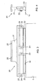
- Figure 2 is a side view of the suction mold cleaning device as shown in Figure 1;
- Figure 3 is a front view of a brush type mold cleaning device; and
- Figure 4 is a side view of the brush type mold cleaning device.
- Figures 1 and 2 show a suction device 1 located between an
upper mold half 2 and alower mold half 3. The suction device 1 includes twooutlets 4 which are adapted to be coupled to a vacuum pump (not shown). Theoutlets 4 are each coupled to amanifold 5. From eachmanifold 5 extends anupper fluid channel 6 and a lower fluid channel 7. Theupper fluid channels 6 merge with each other at anopening 8 which comprises afunnel section 9 and aneck section 10 between thefunnel section 9 and thechannels 6. - Similarly, the lower fluid channels 7 meet at a
lower opening 11 which includes aneck section 12 and afunnel section 13. Theneck section 12 is located between thefunnel section 13 and the lower fluid channel 7. Attached to each side of theopenings rubber strips 14 which extend along the sides of theopenings rubber strips 14 engage withsurfaces lower mold halves - The suction device 1 also includes compressed
air injection tubes 17 mounted at, or adjacent to, thelower opening 11. Theair injection tubes 17 are directed inwardly towards theneck section 12 and downwardly towards thesurface 16 of thelower mold half 3. - The suction device 1 also includes
mounting holes 18 to enable the suction device 1 to be mounted on a robotic off-loader carriage (not shown) of the molding equipment. - It should be noted that the
neck section 12 has a larger cross-sectional area than theneck section 10. Therefore, when theoutlets 4 are connected to a vacuum pump (not shown), there is a greater air flow through theopening 11 than through theopening 8. The air flow through theopening 11 is also enhanced by the compressedair injection tubes 17 which direct compressed air inwardly towards theneck section 12 and against thelower surface 16 of themold half 3. - Figures 3 and 4 show a brush
type cleaning device 20 which includes abody member 21 to which twosilicon rubber brushes 22 are attached by aclamp member 23. Theclamp member 23 clamps thebrushes 22 to thebody member 21 byscrews 24, or any other suitable fastening device. Thebody member 21 also includes mountingholes 25 which enable thecleaning device 20 to be mounted on a robotic on-loader carriage (not shown) of the mold equipment. - As an alternative to, or in addition to, the
silicon brushes 22, thecleaning device 20 may comprise a cleaning cloth, such as a lint-free cleaning cloth. - In use, the suction device 1 is mounted on an off-loader carriage of the molding equipment and the
outlets 4 are attached to a vacuum pump. Thecleaning device 20 is mounted on an on-loader carriage. - Prior to carrying out a molding operation on a substrate and semiconductor chip mounted on a substrate, the
mold halves lower surface 16 of thelower mold half 3 to clean thesurface 16. When the on-loader carriage is fully inserted between themold halves lower mold half 3. The on-loader carriage then moves thecleaning device 20 upward so that the brushes move out of engagement with thesurface 16 and the on-loader carriage is withdrawn from between themold halves - The
mold halves - After the molding operation has been completed, the
mold halves mold halves lower mold halves rubber strips 14 engage with thesurfaces openings air injection tubes 17. As the off-loader carriage is withdrawn from themold halves surfaces mold surfaces mold surfaces - After the off-loader carriage has been completely removed between the
mold halves mold halves mold halves - By providing the suction device 1 with a larger
lower neck section 12, permits more air flow to be extracted through thelower opening 11 than through theupper opening 8. The higher air flow through thelower opening 11 enables more efficient cleaning of thelower mold surface 16 to take into account that the majority of the debris is normally located on thelower mold surface 16 and that gravity hinders removal of foreign particles and debris from thelower mold surface 16. - In addition, the use of air injection adjacent to the lower opening also enhances removal of debris and foreign particles from the
lower surface 16. - The invention also has the advantage that by providing a mold cleaning device on the on-loader, the lower mold surface is cleaned again immediately prior to insertion of the substrate and the semiconductor chip into the mold.
- In addition, it is possible that the brush
type cleaning device 20 could be mounted on the on-loader so as to clean the upper mold half during insertion of the on-loader carriage between the mold halves 2, 3, or that twobrush type devices 20 could be mounted on the on-loader so that both thesurface 16 and thesurface 15 are cleaned simultaneously as the on-loader carriage is inserted between the mold halves 2, 3.
Claims (11)
- Mold cleaning apparatus comprising a manifold (5) adapted to be coupled to a suction device, a first conduit (6) extending from the manifold and having a first opening (8) remote from the manifold, and a second conduit (7) extending from the manifold and having a second opening (11) remote from the manifold, the first and the second openings (8, 11) being directed in opposite directions, characterized in that the first conduit (6) has a section (10) with a cross-sectional area which is less than a cross-sectional area at any point along the length of the second conduit (7).
- Apparatus according to claim 1, wherein the first opening (8) is adapted to engage an upper mold surface (15) of a mold (2, 3) and the second opening (11) is adapted to engage a lower mold surface (16) of the mold.
- Apparatus according to claim 1 or 2, wherein the first and the second openings (8, 11) each comprise a flexible member (14) which is adapted to engage with the respective mold surface (15, 16).
- Apparatus according to claim 3, wherein the flexible members (14) are elastically deformable.
- Apparatus according to any one of claims 1 - 4, further comprising fluid injection means (17) coupled to the second conduit (7), adjacent to the second opening (11), to inject fluid into the opening of the second conduit.
- Apparatus according to claim 5, wherein the first opening (8) is adapted to engage an upper mold surface (15) of a mold (2, 3) and the second opening (11) is adapted to engage a lower mold surface (16) of the mold, and the fluid injection means (17) is mounted on the second conduit (7) to inject fluid towards the lower mold surface when the second opening is engaged with the lower mold surface.
- Apparatus according to any one of claims 1 - 6, further comprising another manifold (5), a third conduit extending (6) from the other manifold to the first opening (8) and a fourth conduit (7) extending from the other manifold to the second opening (11).
- Molding apparatus for molding a material around a semiconductor chip and a substrate on which the semiconductor chip is mounted, the mold (2, 3) comprising a lower mold half (3) and an upper mold half (2), the mold halves being movable between an open position, in which a substrate and a semiconductor chip mounted thereon can be inserted into the mold halves and a molded substrate and semiconductor chip can be removed from the mold halves, and a closed position, in which a molding operation can be performed; a first movable carriage adapted to insert a substrate and a semiconductor chip mounted thereon into the mold; a second carriage adapted to remove a molded substrate and semiconductor chip from the mold; a first mold cleaning device (20) mounted on the first carriage to clean a surface (15, 16) of the mold halves (2, 3) before a substrate and a semiconductor chip are placed in the mold; and a second cleaning device mounted on the second carriage to clean the mold halves after a molded substrate and semiconductor chip is removed from the mold, said second cleaning device comprises the mold cleaning apparatus according to one of the preceding claims.
- Apparatus according to claim 8, wherein the first cleaning device (20) comprises a brush (22) which engages with a surface (15, 16) of the mold halves (2, 3) during cleaning.
- Apparatus according to claim 8 or 9, wherein the first cleaning device (20) comprises a fabric material which engages with a surface of the mold halves during cleaning.
- Apparatus according to any one of claims 8 - 10, wherein the first cleaning device is adapted to clean the lower mold half (3).
Applications Claiming Priority (2)
| Application Number | Priority Date | Filing Date | Title |
|---|---|---|---|
| US901256 | 2001-07-09 | ||
| US09/901,256 US6736627B2 (en) | 2001-07-09 | 2001-07-09 | Mold cleaning apparatus |
Publications (3)
| Publication Number | Publication Date |
|---|---|
| EP1275484A2 EP1275484A2 (en) | 2003-01-15 |
| EP1275484A3 EP1275484A3 (en) | 2003-08-27 |
| EP1275484B1 true EP1275484B1 (en) | 2006-09-20 |
Family
ID=25413828
Family Applications (1)
| Application Number | Title | Priority Date | Filing Date |
|---|---|---|---|
| EP02078295A Expired - Lifetime EP1275484B1 (en) | 2001-07-09 | 2002-07-05 | Mold cleaning apparatus |
Country Status (5)
| Country | Link |
|---|---|
| US (1) | US6736627B2 (en) |
| EP (1) | EP1275484B1 (en) |
| MY (1) | MY122885A (en) |
| SG (1) | SG111951A1 (en) |
| TW (1) | TWI282112B (en) |
Families Citing this family (4)
| Publication number | Priority date | Publication date | Assignee | Title |
|---|---|---|---|---|
| US20070047437A1 (en) * | 2005-08-24 | 2007-03-01 | Rainer Bachl | Method and apparatus for controlling retransmissions in a wireless communications system |
| JP2016168732A (en) * | 2015-03-12 | 2016-09-23 | ファナック株式会社 | Injection molding system for performing mold cleaning |
| CN108189288B (en) * | 2018-03-01 | 2024-04-16 | 日荣半导体(上海)有限公司 | Sweep template and sweep mould equipment |
| ES2965466T3 (en) * | 2021-02-15 | 2024-04-15 | Klingspor Windpower Aps | Device for treating a mold surface and use of the device |
Family Cites Families (8)
| Publication number | Priority date | Publication date | Assignee | Title |
|---|---|---|---|---|
| EP0278683B1 (en) * | 1987-02-10 | 1992-07-08 | Sumitomo Chemical Company, Limited | Automatic cleaning device for use in the thermoplastics extrusion plastometer |
| JPH05192741A (en) | 1992-01-18 | 1993-08-03 | Toyota Motor Corp | Device for cleaning die |
| JPH07156157A (en) | 1993-12-09 | 1995-06-20 | Fujitsu Miyagi Electron:Kk | Cleaning method and cleaning device for resin molding die |
| NL1003366C2 (en) | 1996-06-18 | 1997-12-19 | Fico Bv | Apparatus and method for encapsulating products. |
| JPH11151722A (en) | 1997-11-20 | 1999-06-08 | Bando Chem Ind Ltd | Work removal device |
| JP3825161B2 (en) | 1997-12-02 | 2006-09-20 | 株式会社サイネックス | Semiconductor mold equipment |
| JPH11198151A (en) | 1998-01-20 | 1999-07-27 | Hitachi Ltd | Molding mold cleaning sheet and molding mold cleaning method using the same |
| JP3834782B2 (en) | 1998-04-11 | 2006-10-18 | アピックヤマダ株式会社 | Molding equipment for resin molding |
-
2001
- 2001-07-09 US US09/901,256 patent/US6736627B2/en not_active Expired - Lifetime
-
2002
- 2002-07-05 EP EP02078295A patent/EP1275484B1/en not_active Expired - Lifetime
- 2002-07-05 SG SG200204125A patent/SG111951A1/en unknown
- 2002-07-08 MY MYPI20022578A patent/MY122885A/en unknown
- 2002-07-09 TW TW091115239A patent/TWI282112B/en not_active IP Right Cessation
Also Published As
| Publication number | Publication date |
|---|---|
| MY122885A (en) | 2006-05-31 |
| US20030008027A1 (en) | 2003-01-09 |
| US6736627B2 (en) | 2004-05-18 |
| EP1275484A3 (en) | 2003-08-27 |
| TWI282112B (en) | 2007-06-01 |
| SG111951A1 (en) | 2005-06-29 |
| EP1275484A2 (en) | 2003-01-15 |
Similar Documents
| Publication | Publication Date | Title |
|---|---|---|
| US10258207B2 (en) | Portable hard surface cleaning appliance | |
| CN102165858B (en) | Electronic component mounting device and mounting method | |
| US20060060136A1 (en) | Semiconductor producing device using mini-environment system | |
| TWI837481B (en) | Resin sealing device and cleaning method | |
| KR101866201B1 (en) | Apparatus for cleaning an object | |
| KR20120035033A (en) | Unit for removing foreign matter and apparatus and method for semiconductor packaging using the same | |
| US6736627B2 (en) | Mold cleaning apparatus | |
| TW201408387A (en) | Cleaning head | |
| CN109793455B (en) | Renewable dust collector | |
| US20020166504A1 (en) | Cleaner for molding apparatus of semiconductor chip packages | |
| KR100927293B1 (en) | Mini-environment type semiconductor manufacturing device | |
| KR101391251B1 (en) | A nozzle-holder for nozzle cleaning device | |
| KR102301676B1 (en) | Sand blast apparatus for flash of lead frame | |
| CN109109217A (en) | It is a kind of to integrate drying integrated equipment for waste plastics cleaning | |
| CN219880790U (en) | Automatic cleaning structure for suction nozzle of circuit board chip mounter | |
| RU2246245C2 (en) | Auxiliary cleaning apparatus for vacuum cleaner | |
| KR101515722B1 (en) | Apparatus for cleaning a mold | |
| KR100656249B1 (en) | Cleaner of Semiconductor Package | |
| JP3572287B2 (en) | Resin sealing device | |
| TWI642131B (en) | Method and apparatus for cleaning a substrate | |
| KR20170064756A (en) | Magazine transferring module and die bonding apparatus having the same | |
| JPH05138685A (en) | Molding equipment | |
| KR100813214B1 (en) | Cleaning device for dicing tape attachment | |
| CN220197277U (en) | Polishing positioning jig for metal mobile phone shell | |
| CN218552208U (en) | Dry and wet dust collector capable of cleaning interior of automobile |
Legal Events
| Date | Code | Title | Description |
|---|---|---|---|
| PUAI | Public reference made under article 153(3) epc to a published international application that has entered the european phase |
Free format text: ORIGINAL CODE: 0009012 |
|
| AK | Designated contracting states |
Kind code of ref document: A2 Designated state(s): AT BE BG CH CY CZ DE DK EE ES FI FR GB GR IE IT LI LU MC NL PT SE SK TR |
|
| AX | Request for extension of the european patent |
Free format text: AL;LT;LV;MK;RO;SI |
|
| PUAL | Search report despatched |
Free format text: ORIGINAL CODE: 0009013 |
|
| AK | Designated contracting states |
Designated state(s): AT BE BG CH CY CZ DE DK EE ES FI FR GB GR IE IT LI LU MC NL PT SE SK TR |
|
| AX | Request for extension of the european patent |
Extension state: AL LT LV MK RO SI |
|
| 17P | Request for examination filed |
Effective date: 20031210 |
|
| 17Q | First examination report despatched |
Effective date: 20040303 |
|
| AKX | Designation fees paid |
Designated state(s): NL |
|
| REG | Reference to a national code |
Ref country code: DE Ref legal event code: 8566 |
|
| GRAP | Despatch of communication of intention to grant a patent |
Free format text: ORIGINAL CODE: EPIDOSNIGR1 |
|
| GRAS | Grant fee paid |
Free format text: ORIGINAL CODE: EPIDOSNIGR3 |
|
| GRAA | (expected) grant |
Free format text: ORIGINAL CODE: 0009210 |
|
| AK | Designated contracting states |
Kind code of ref document: B1 Designated state(s): NL |
|
| PLBE | No opposition filed within time limit |
Free format text: ORIGINAL CODE: 0009261 |
|
| STAA | Information on the status of an ep patent application or granted ep patent |
Free format text: STATUS: NO OPPOSITION FILED WITHIN TIME LIMIT |
|
| 26N | No opposition filed |
Effective date: 20070621 |
|
| PGFP | Annual fee paid to national office [announced via postgrant information from national office to epo] |
Ref country code: NL Payment date: 20210716 Year of fee payment: 20 |
|
| REG | Reference to a national code |
Ref country code: NL Ref legal event code: MK Effective date: 20220704 |