EP1274580B1 - Doppelbandpresse - Google Patents
Doppelbandpresse Download PDFInfo
- Publication number
- EP1274580B1 EP1274580B1 EP00963628A EP00963628A EP1274580B1 EP 1274580 B1 EP1274580 B1 EP 1274580B1 EP 00963628 A EP00963628 A EP 00963628A EP 00963628 A EP00963628 A EP 00963628A EP 1274580 B1 EP1274580 B1 EP 1274580B1
- Authority
- EP
- European Patent Office
- Prior art keywords
- pressure
- section
- pressure box
- heating
- belts
- Prior art date
- Legal status (The legal status is an assumption and is not a legal conclusion. Google has not performed a legal analysis and makes no representation as to the accuracy of the status listed.)
- Expired - Lifetime
Links
- 238000001816 cooling Methods 0.000 claims abstract description 57
- 239000000758 substrate Substances 0.000 claims abstract description 53
- 238000003475 lamination Methods 0.000 claims abstract description 20
- 238000009824 pressure lamination Methods 0.000 claims abstract description 13
- 238000010438 heat treatment Methods 0.000 claims description 45
- 229910052751 metal Inorganic materials 0.000 claims description 11
- 239000002184 metal Substances 0.000 claims description 11
- XLYOFNOQVPJJNP-UHFFFAOYSA-N water Substances O XLYOFNOQVPJJNP-UHFFFAOYSA-N 0.000 claims description 8
- 229920001971 elastomer Polymers 0.000 claims description 7
- 229920006362 Teflon® Polymers 0.000 claims description 6
- 239000012530 fluid Substances 0.000 claims description 6
- 239000004809 Teflon Substances 0.000 claims description 2
- 230000003213 activating effect Effects 0.000 claims description 2
- 239000004745 nonwoven fabric Substances 0.000 abstract description 21
- 239000000853 adhesive Substances 0.000 abstract description 17
- 230000001070 adhesive effect Effects 0.000 abstract description 17
- 239000004744 fabric Substances 0.000 abstract description 13
- 238000000034 method Methods 0.000 abstract description 6
- 239000002759 woven fabric Substances 0.000 abstract description 5
- 230000009977 dual effect Effects 0.000 abstract description 4
- 238000004519 manufacturing process Methods 0.000 abstract description 4
- 238000005304 joining Methods 0.000 abstract description 2
- 239000000463 material Substances 0.000 description 26
- 229910052782 aluminium Inorganic materials 0.000 description 10
- XAGFODPZIPBFFR-UHFFFAOYSA-N aluminium Chemical compound [Al] XAGFODPZIPBFFR-UHFFFAOYSA-N 0.000 description 10
- 239000000835 fiber Substances 0.000 description 9
- 229910000831 Steel Inorganic materials 0.000 description 6
- 230000000694 effects Effects 0.000 description 6
- 229920001343 polytetrafluoroethylene Polymers 0.000 description 6
- 239000004810 polytetrafluoroethylene Substances 0.000 description 6
- 238000007789 sealing Methods 0.000 description 6
- 239000010959 steel Substances 0.000 description 6
- 239000002131 composite material Substances 0.000 description 4
- 238000010030 laminating Methods 0.000 description 4
- 229920001169 thermoplastic Polymers 0.000 description 4
- 239000004416 thermosoftening plastic Substances 0.000 description 4
- 239000011152 fibreglass Substances 0.000 description 3
- 238000002844 melting Methods 0.000 description 3
- 230000008018 melting Effects 0.000 description 3
- 239000004699 Ultra-high molecular weight polyethylene Substances 0.000 description 2
- 239000007788 liquid Substances 0.000 description 2
- 239000000203 mixture Substances 0.000 description 2
- 230000004048 modification Effects 0.000 description 2
- 238000012986 modification Methods 0.000 description 2
- 239000005373 porous glass Substances 0.000 description 2
- 229920002994 synthetic fiber Polymers 0.000 description 2
- 229920000785 ultra high molecular weight polyethylene Polymers 0.000 description 2
- RNFJDJUURJAICM-UHFFFAOYSA-N 2,2,4,4,6,6-hexaphenoxy-1,3,5-triaza-2$l^{5},4$l^{5},6$l^{5}-triphosphacyclohexa-1,3,5-triene Chemical compound N=1P(OC=2C=CC=CC=2)(OC=2C=CC=CC=2)=NP(OC=2C=CC=CC=2)(OC=2C=CC=CC=2)=NP=1(OC=1C=CC=CC=1)OC1=CC=CC=C1 RNFJDJUURJAICM-UHFFFAOYSA-N 0.000 description 1
- QEDQZYNGDXULGO-UHFFFAOYSA-N 3-methyl-2-(3-methylphenyl)morpholine Chemical compound CC1NCCOC1C1=CC=CC(C)=C1 QEDQZYNGDXULGO-UHFFFAOYSA-N 0.000 description 1
- 239000004831 Hot glue Substances 0.000 description 1
- 239000004677 Nylon Substances 0.000 description 1
- 239000002313 adhesive film Substances 0.000 description 1
- 239000010425 asbestos Substances 0.000 description 1
- 230000015572 biosynthetic process Effects 0.000 description 1
- 239000000470 constituent Substances 0.000 description 1
- 239000000498 cooling water Substances 0.000 description 1
- 238000006073 displacement reaction Methods 0.000 description 1
- 239000002657 fibrous material Substances 0.000 description 1
- 239000003063 flame retardant Substances 0.000 description 1
- 239000011521 glass Substances 0.000 description 1
- 230000005484 gravity Effects 0.000 description 1
- 239000002648 laminated material Substances 0.000 description 1
- 230000003278 mimic effect Effects 0.000 description 1
- 229920001778 nylon Polymers 0.000 description 1
- 230000002093 peripheral effect Effects 0.000 description 1
- 229920000728 polyester Polymers 0.000 description 1
- 229920000642 polymer Polymers 0.000 description 1
- 238000002360 preparation method Methods 0.000 description 1
- 230000000284 resting effect Effects 0.000 description 1
- 229910052895 riebeckite Inorganic materials 0.000 description 1
- 229920002379 silicone rubber Polymers 0.000 description 1
- 239000004945 silicone rubber Substances 0.000 description 1
- 239000007787 solid Substances 0.000 description 1
- 239000007921 spray Substances 0.000 description 1
- 239000000126 substance Substances 0.000 description 1
- 239000012209 synthetic fiber Substances 0.000 description 1
- 229920006344 thermoplastic copolyester Polymers 0.000 description 1
- 239000012815 thermoplastic material Substances 0.000 description 1
- 230000000007 visual effect Effects 0.000 description 1
Images


Classifications
-
- D—TEXTILES; PAPER
- D06—TREATMENT OF TEXTILES OR THE LIKE; LAUNDERING; FLEXIBLE MATERIALS NOT OTHERWISE PROVIDED FOR
- D06H—MARKING, INSPECTING, SEAMING OR SEVERING TEXTILE MATERIALS
- D06H7/00—Apparatus or processes for cutting, or otherwise severing, specially adapted for the cutting, or otherwise severing, of textile materials
- D06H7/04—Apparatus or processes for cutting, or otherwise severing, specially adapted for the cutting, or otherwise severing, of textile materials longitudinally
- D06H7/08—Apparatus or processes for cutting, or otherwise severing, specially adapted for the cutting, or otherwise severing, of textile materials longitudinally for cutting tubular fabric longitudinally
-
- B—PERFORMING OPERATIONS; TRANSPORTING
- B32—LAYERED PRODUCTS
- B32B—LAYERED PRODUCTS, i.e. PRODUCTS BUILT-UP OF STRATA OF FLAT OR NON-FLAT, e.g. CELLULAR OR HONEYCOMB, FORM
- B32B37/00—Methods or apparatus for laminating, e.g. by curing or by ultrasonic bonding
- B32B37/10—Methods or apparatus for laminating, e.g. by curing or by ultrasonic bonding characterised by the pressing technique, e.g. using action of vacuum or fluid pressure
- B32B37/1027—Pressing using at least one press band
-
- B—PERFORMING OPERATIONS; TRANSPORTING
- B32—LAYERED PRODUCTS
- B32B—LAYERED PRODUCTS, i.e. PRODUCTS BUILT-UP OF STRATA OF FLAT OR NON-FLAT, e.g. CELLULAR OR HONEYCOMB, FORM
- B32B5/00—Layered products characterised by the non- homogeneity or physical structure, i.e. comprising a fibrous, filamentary, particulate or foam layer; Layered products characterised by having a layer differing constitutionally or physically in different parts
- B32B5/22—Layered products characterised by the non- homogeneity or physical structure, i.e. comprising a fibrous, filamentary, particulate or foam layer; Layered products characterised by having a layer differing constitutionally or physically in different parts characterised by the presence of two or more layers which are next to each other and are fibrous, filamentary, formed of particles or foamed
- B32B5/24—Layered products characterised by the non- homogeneity or physical structure, i.e. comprising a fibrous, filamentary, particulate or foam layer; Layered products characterised by having a layer differing constitutionally or physically in different parts characterised by the presence of two or more layers which are next to each other and are fibrous, filamentary, formed of particles or foamed one layer being a fibrous or filamentary layer
- B32B5/26—Layered products characterised by the non- homogeneity or physical structure, i.e. comprising a fibrous, filamentary, particulate or foam layer; Layered products characterised by having a layer differing constitutionally or physically in different parts characterised by the presence of two or more layers which are next to each other and are fibrous, filamentary, formed of particles or foamed one layer being a fibrous or filamentary layer another layer next to it also being fibrous or filamentary
-
- B—PERFORMING OPERATIONS; TRANSPORTING
- B65—CONVEYING; PACKING; STORING; HANDLING THIN OR FILAMENTARY MATERIAL
- B65H—HANDLING THIN OR FILAMENTARY MATERIAL, e.g. SHEETS, WEBS, CABLES
- B65H81/00—Methods, apparatus, or devices for covering or wrapping cores by winding webs, tapes, or filamentary material, not otherwise provided for
-
- D—TEXTILES; PAPER
- D04—BRAIDING; LACE-MAKING; KNITTING; TRIMMINGS; NON-WOVEN FABRICS
- D04H—MAKING TEXTILE FABRICS, e.g. FROM FIBRES OR FILAMENTARY MATERIAL; FABRICS MADE BY SUCH PROCESSES OR APPARATUS, e.g. FELTS, NON-WOVEN FABRICS; COTTON-WOOL; WADDING ; NON-WOVEN FABRICS FROM STAPLE FIBRES, FILAMENTS OR YARNS, BONDED WITH AT LEAST ONE WEB-LIKE MATERIAL DURING THEIR CONSOLIDATION
- D04H3/00—Non-woven fabrics formed wholly or mainly of yarns or like filamentary material of substantial length
- D04H3/02—Non-woven fabrics formed wholly or mainly of yarns or like filamentary material of substantial length characterised by the method of forming fleeces or layers, e.g. reorientation of yarns or filaments
- D04H3/07—Non-woven fabrics formed wholly or mainly of yarns or like filamentary material of substantial length characterised by the method of forming fleeces or layers, e.g. reorientation of yarns or filaments otherwise than in a plane, e.g. in a tubular way
-
- D—TEXTILES; PAPER
- D04—BRAIDING; LACE-MAKING; KNITTING; TRIMMINGS; NON-WOVEN FABRICS
- D04H—MAKING TEXTILE FABRICS, e.g. FROM FIBRES OR FILAMENTARY MATERIAL; FABRICS MADE BY SUCH PROCESSES OR APPARATUS, e.g. FELTS, NON-WOVEN FABRICS; COTTON-WOOL; WADDING ; NON-WOVEN FABRICS FROM STAPLE FIBRES, FILAMENTS OR YARNS, BONDED WITH AT LEAST ONE WEB-LIKE MATERIAL DURING THEIR CONSOLIDATION
- D04H3/00—Non-woven fabrics formed wholly or mainly of yarns or like filamentary material of substantial length
- D04H3/08—Non-woven fabrics formed wholly or mainly of yarns or like filamentary material of substantial length characterised by the method of strengthening or consolidating
- D04H3/12—Non-woven fabrics formed wholly or mainly of yarns or like filamentary material of substantial length characterised by the method of strengthening or consolidating with filaments or yarns secured together by chemical or thermo-activatable bonding agents, e.g. adhesives, applied or incorporated in liquid or solid form
-
- H—ELECTRICITY
- H05—ELECTRIC TECHNIQUES NOT OTHERWISE PROVIDED FOR
- H05K—PRINTED CIRCUITS; CASINGS OR CONSTRUCTIONAL DETAILS OF ELECTRIC APPARATUS; MANUFACTURE OF ASSEMBLAGES OF ELECTRICAL COMPONENTS
- H05K3/00—Apparatus or processes for manufacturing printed circuits
- H05K3/02—Apparatus or processes for manufacturing printed circuits in which the conductive material is applied to the surface of the insulating support and is thereafter removed from such areas of the surface which are not intended for current conducting or shielding
- H05K3/022—Processes for manufacturing precursors of printed circuits, i.e. copper-clad substrates
Definitions
- This invention relates to a lamination apparatus and in particular to a dual belt driven, continuous pressure lamination apparatus that utilizes pressure, heat and cooling to bond at least two substrates (plies) with an adhesive between the layers of the substrates.
- the laminator of the present invention overcomes many of the disadvantages of prior art laminators, including shrinkage of materials, and the like.
- JP-A-01 210 318, JP-A-63 267 525, EP-A-0 255 596, US-A-4 687 528, EP-A-0 470 584, DE-A-30 46 431, DE-A-30 46 432, US-A- 3 591 434, US-A-4 498 941 and US-A-5 352 321 describe various pressure lamination arrangements.
- the present invention relates to an apparatus according to the preamble of claim 1.
- Such an apparatus is known in particular from US-A-4 498 941.
- This known apparatus comprises a solid sealing ring around the upper and lower pressure box sections.
- the present invention provides a pressure lamination apparatus as defined in appended claim 1.
- the bladders improve the flexibility of the pressure seals in a simple and efficient way.
- This invention relates to a lamination apparatus and in particular to a dual belt driven, continuous pressure lamination apparatus that utilizes pressure, heat and cooling to bond at least two substrates (plies) with an adhesive between the layers of the substrates.
- the laminator of the present invention can be employed to make a variety of composite and/or reinforced materials.
- One or more of the component parts of the laminate i.e., the substrates or plies
- the substrates or plies may be a woven fabric material, a non-woven fabric web, or a mat of fibers.
- Adhesive materials preferably thermoplastic materials, are used to bond the various substrates in the laminate construct. These materials may be melted and remelted over and over.
- thermoplastic copolyester adhesives are preferred, as these materials may be selected to have a melting temperature below the melting temperature of the yarns.
- Industrial type laminates that may be formed using the laminator of the present invention include natural and/or synthetic fabric-based, asbestos-based, glass-based, nylon-based, flame-retardant and/or flame-resistant based, and mixtures thereof. Laminates of other materials may also be prepared as will be appreciated by those having ordinary skill in the field.
- Non-woven fabrics are one especially preferred class of materials used as the plies or substrates in the pressure laminator of the present invention.
- Non-woven fabrics are similar to woven and knitted fabrics in that all are planar, inherently flexible, porous structures composed of natural or synthetic fiber materials (i.e., yarns, threads, or filaments).
- Non-woven fabrics are unique in that they can be engineered to resemble woven or knitted fabrics, but they can also be made to have superior physical characteristics over woven or knitted fabrics.
- non-woven fabrics are highly influenced by the properties of their constituent fibers and the manner in which the non-woven fabric is prepared. Typical methods for preparing non-woven fabrics include mechanical, chemical and thermal interlocking of layers or networks of the fiber materials.
- At least two non-woven fabric substrates may be used, one of the fabric substrate representing the weft strands and another representing the warp strands.
- the adhesive used to bond the non-woven substrates should be activated by heat during the lamination process. The combination of pressure, heating to activate the adhesive and rapid cooling of the joined substrates minimizes shrinkage and sets the yarn size in the final non-woven fabric laminate. In addition, because the laminate is being formed under pressure, the warp and weft yarns are forced into intimate contact, giving the final laminate the appearance of a woven product.
- a lamination apparatus embodying the present invention has an outer housing or frame in which a rectangular pressure box is mounted.
- the shape of the box need not be rectangular, but this shape is currently preferred.
- the pressure box comprises two spaced apart sections, an upper section and a lower section, each of which has pressure seals along its four edges, and each of which is further provided with a plurality of both heating and cooling elements.
- Two counter rotating drive belts, an upper drive belt and a lower drive belt, contact one another at and together run through a space between the two sections of the pressure box.
- the belts are dimensionally larger (length and width) than the pressure box. This is necessary to permit pressurization of the box, both above and below the two belts.
- One belt is driven in a clockwise manner and the other belt is driven in a counterclockwise manner. Once the belts are in motion, one end of the pressure box is the inlet (feed) end and one end is the outlet end of the laminator.
- the lower section of the pressure box is mounted rigidly to the frame or housing, whereas the upper section of the pressure box can be adjusted as necessary to permit access to the interior of the box. Normally, the sections are spaced apart sufficiently to permit passage of the drive belts there through under pressure (or in a depressurized state), with or without material to be laminated there between.
- substrate materials to be laminated are passed through a pressure seal at the inlet end of the pressure box, and into the space between the two drive belts.
- Air pressure applied to the upper and lower sections of the pressure box is used to compress the air-impermeable belts toward one another, creating a diaphragm effect between the belts, thereby compressing the substrates situated there between.
- the upper and lower sections of the pressure box are equipped with a plurality of heating and cooling elements, which are used to activate and set the thermoplastic adhesive between the substrate layers.
- the plurality of heating and cooling bars located in the lower section of the pressure box are rigidly mounted, whereas the plurality of heating an cooling bars in the upper section of the pressure box are mounted so as to float on top of the materials being laminated.
- This arrangement has been found to be especially useful in the preparation of non-woven fabrics. Shrinkage is minimized or eliminated and the final laminate has the physical characteristics (feel and appearance) of a thermomechanically finished fabric.
- At least about 10%, preferably at least about 25% and most preferably about 50% of the box interior at the inlet end of the pressure box is provided with heat bars
- the remainder of the pressure box again, at least about 10%, preferably at least about 25% and most preferably about 50% of the box interior, is provided with cooling bars.
- the heating bars are ideally located at the inlet end of the pressure box and the cooling bars are ideally located at the outlet end of the pressure box. If desired, multiple zones of heating and cooling could be included within the pressure box; e.g., heat/cool, heat/cool, heat/cool, etc.
- Movement of the two belts through the pressure box allows for the continuous feeding of substrate materials and thermoplastic adhesive enter the laminator through an entry pressure seal.
- the substrates are nipped or pressed together by the diaphragm effect caused by the pressure applied to the belts.
- the pressed substrates are then heated under pressure, melting the thermoplastic adhesive. This allows the substrate layers to come closer together, with at least some portions of the warp and weft yarn strands becoming coplanar or nearly coplanar.
- the heated substrates are then cooled, while still under pressure, forming the final laminate.
- the cooled laminate exits the pressure box through an exit pressure seal, where it is collected as desired.
- the thickness of the laminate at the outlet end of the laminator is at least 5%, preferably at least 10% and most preferably at least about 20% less than the combined thickness of the substrates and thermoplastic adhesive, as measured at the inlet end of the laminator.
- the current rectangular pressure has a pressure area of about 967800 mm 2 (1500 square inches (in 2 )).
- the drive belts which are substantially non-porous, are pressurized from both sides of the pressure box with air (or other fluid medium) pressure of at least 13.78 kPa (2 psi), preferably at least about 34.45 kPa (5 psi), and most preferably at least about 68.9 kPa (10 psi). Higher pressures can be achieved with modification of the equipment to support and sustain the same.
- This pressure applied to the belts is equivalent to a compressive weight (force) ranging from about 2268 kg (5000 lbs) to about 22680 kg (50,000 lbs), applied over the 967800 mm 2 (1500 in 2 ) area of the current pressure box.
- a compressive force from about 4536 kg (10,000 lbs) to about 11340 kg (25,000 lbs) is typical, and a compressive force of about 6804 kg (15,000 lbs) (at 68.9 kPa (10 psi) gauge) has been found to be especially preferred to date.
- a fluid pressure medium e.g., air (or other gas, e.g., steam) or liquid (e.g., water, oil, etc)
- air or other gas, e.g., steam
- liquid e.g., water, oil, etc
- This invention may be used to manufacture non-woven fabrics using the pressure lamination apparatus.
- the pressure laminator of the present invention has been specifically designed to permit the permanent joining of at least two non-woven fabric substrates with an adhesive between the fabric substrates, with little or no shrinkage occurring, during the lamination process. While not wishing to be bound by theory, it is believed that shrinkage is prevented or limited herein, due to the high pressure on the belts, which prevents the laminate from slipping, thereby preventing or limiting shrinkage.
- the resulting non-woven composite fabric advantageously has the appearance of a woven fabric, but has superior strength characteristics there over.
- the pressure laminator of the present invention can have other uses, for example, printed circuit board substrate manufacture, decorative laminating, industrial laminating, and the like, as will be appreciated by those having ordinary skill in this art.
- a bladder seal according to figs. 7A, 7B and 7C is used in the apparatus according to the invention whereas the seals illustrated on figs. 4,5 and 6 do not belong to the present invention.
- the present invention is directed to a lamination apparatus and in particular to a dual belt driven, continuous pressure lamination apparatus that utilizes pressure, heat and cooling to bond at least two substrates (plies) with an adhesive between the layers of the substrates.
- the laminator of the present invention could also be used to stabilize a single ply material.
- the pressure lamination apparatus of this invention comprises a housing or frame in which a pressure box is mounted.
- the pressure box comprises two spaced apart pressure sections, an upper section and a lower section, wherein the space formed between the two pressure sections defines the lamination section.
- Two counter rotating drive belts, an upper drive belt and a lower drive belt, are rotatably mounted in the housing or frame, and the belts contact one another and are pulled through the lamination section by drive rollers mounted at the outlet end.
- a pressure generator is used to supplying air (or other fluid medium - liquid or gas) pressure to the upper and lower sections of the pressure box for compressing substrate materials carried between the two drive belts. Pressure is maintained because the box has pressure seals all around the points of contact with the belt.
- metal side seals are provided on the sides of both the upper and lower sections of the pressure box.
- Metal inlet and outlet seals are also provided on the upper and lower sections of the pressure box, ensuring that the desired diaphragm effect can be created therein.
- Teffon® PTFE
- Rubber inlet and outlet seals are also provided on the upper and lower sections of the pressure box, ensuring that the desired diaphragm effect can be created therein.
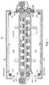
- FIG. 1 a number of the essential components of the preferred pressure box 401 used in the pressure laminator of the present invention 400 are shown in cross-section.
- two rotatable belts top belt 402 and bottom belt 404, mounted on a plurality of support rollers (top - 410, 420, 430; bottom - 510, 520, 530), are pulled through the pressure box 401, between the upper section 412 and the lower section 414, entering at the inlet end 416 and exiting at the outlet end 418, by their respective drive rollers 550 (top) and 650 (bottom).
- Alignment of the two rotating belts 402 and 404 is maintained by an electric alignment system comprising an alignment carriage 100, alignment pivot 110, electric alignment servo 120 and electric alignment eyes 130. If either of the belts moves out of alignment, the electric eye 130 detects the same and activates the alignment servo, which causes the belt to be adjusted as necessary by lateral movement of the alignment carriage 100.
- eight spaced apart radiant heat bars (310A, 310B, 310C, 310D ... 310H) are shown at the inlet end 416 of pressure box 401 and eight spaced apart cooling bars (320A, 320B, 320C, 320D ... 320H) are shown at the outlet end 418 of pressure box 401.
- Four of the heat bars are rigidly mounted in the lower section 414 of the pressure box 401, namely heat bars 310A, 310C, 310E and 310G.
- the other four radiant heat bars (310B, 310D, 310F and 310H) are flexibly mounted such that they float above the upper belt, permitting materials of varied thickness to pass there under.
- cooling bars 320A, 320C, 320E and 320G are rigidly mounted in the lower section 414 of the pressure box 401, namely cooling bars 320A, 320C, 320E and 320G.
- the other four cooling bars (320B, 320D, 320F and 320H) are flexibly mounted such that they float above the upper belt, permitting materials of varied thickness to pass there under.
- the plurality of heating and cooling bars are preferably arranged in a staggered configuration.
- the substrate is heated from below, then above, then below, etc., and the cooling is accomplished in the same manner; the substrate is cooled from below, then above, then below, etc.
- This arrangement permits rapid and uniform heating, as well as rapid and uniform cooling of the substrate materials being laminated in the pressure laminator.
- the uniformity of heating and cooling under pressure leads to improved physical characteristics of the resulting laminates. In the case of non-woven fabrics laminated in this manner, shrinkage of the fabrics is held to a minimum and the resulting laminated material has the appearance and feel of a woven fabric.
- At least 75 percent of the belt width is heated and cooled by these elements.
- the central 22 inches (0.56 m) are heated and cooled.
- the central 60 inches (1.5 m) would be heated and cooled.
- the Reliant ER177A heat bars (England) are each provided with a thermocouple to measure the temperature delivered to the belts.
- the cooling bars are each provided with water fed cooling pipes.
- the heating and cooling is accomplished by steam and cold water; each fed to an appropriate section of the laminator, in both the upper and lower sections.
- a high-pressure gas and fluid medium creates both pressure and the requisite heating/cooling action that was alternatively achieved by the heating and cooling bars together with high-pressure air.
- infra-red heating may also be employed in this embodiment, and cooling may be accomplished by other means, including water spray, providing non-contact heating and/or cooling options.
- the thickness of the PTFE impregnated fiberglass belt can be modified as desired, and depends on the nature of the materials being laminated and the desired operating speed in feet per minute (fpm).
- a belt thickness ranging from 50.8 to 508 ⁇ m (2 to 20 mil), preferably 127 to 381 ⁇ m (5 to 15 mil) has been found satisfactory.
- Belts of 355.6 ⁇ m (14-mil) thickness have been operated at 5 fpm (1.52 mpm), with a temperature of 380°F (193.3°C) being delivered to the substrates.
- Belts of 127 ⁇ m (5-mil) thickness have been operated at 12 fpm (3.7 meters/min), with a temperature of 380°F (193.3°C) being delivered to the substrates.
- Optimum belt speeds of 50, 60, 70 ... 100 fpm (15.2, 18.3, 21.3, ... 30.48 mpm) can be achieved by modification of the belt thickness and/or composition.
- the optimum belt speed for non-woven fabric lamination is currently believed to be 60-70 fpm (18.3 - 21.3 mpm).
- Another way in which to achieve higher speeds is to simply increase the size of the laminator apparatus.
- the current preferred apparatus has a length of about 4 feet (1.2 meters). Increasing the size 2-10X would allow for faster operating speeds.
- the substrate material may create a counter-pressure as any entrapped air in the substrates expands.
- at lease one (or both) of the PTFE (Teflon®) impregnated fiberglass drive belts used in the pressure laminator of the present invention can be modified on the outside edges, to comprise a thick (about 0.125 inch or 3.175 mm) porous glass fiber mat. This porous glass fiber mat allows the expanded air from the heated laminate to escape via this sideways (transverse) porosity.
- Figure 2 illustrates in cross-section, the end view of pressure box 401, showing in particular the air pressure feed line 600, and the preferred points of contact thereof 602 and 604 with the upper section 412 and lower section 414 of the pressure box, respectively.
- the pressure box is advantageously made out of metal, such as aluminum (from 50.8 to 127 mm (2 to 5 inches) thick) and is held together by a plurality of threaded steel rods and nuts 606 and 608. As shown in Figs. 2 and 4, the heating and cooling bars located in the lower section 414 of the pressure box are locked in place at each end by a fixed bracket 820.
- the heating and cooling bars located in the upper section 412 of the pressure box ride on a pin bracket mount 800/812, which allows upward motion of the bars, while gravity keeps the bars resting on the upper belt.
- a plurality of cooling water lines, inlet 614 and outlet 616 are also shown in Fig. 2.
- the electrical heating wires (not shown) are provided in a manner similar to the water lines.
- Figure 3 illustrates a top view of the interior of the upper section 412 of the pressure box 401, showing the currently preferred arrangement of the upper heating bars (310B, 310D, 310F and 310H) and cooling bars (320B, 320D, 320F and 320H).
- the pressurized box 401 is held together by steel bars 500 mounted to the threaded rods 606 shown in the four corners. Not shown in this illustration are the nuts that thread thereon.
- the sides 402 of the housing or frame, to which the steel bars and all rollers and controls are mounted, are also shown in this drawing.
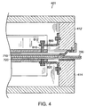
- Figure 4 illustrates, the pin bracket for the upper section, vertically displaceable, heating and cooling bars.
- the pin bracket comprises a steel mounting bracket 800, fixed at one end to the aluminum side wall of the upper section 412 of the pressure box.
- a slot (not shown) is provided near the opposite end of bracket 800, through which a post 810 rides.
- the post 810 is mounted to the top of the heating or cooling bar at one end and capped at the opposite end 812, thereby limiting the vertical displacement distance of the heating and cooling bars.
- the bracket for the lower section heating and cooling bars 820 is also a steel bracket, but it is rigidly attached to both the heating and cooling bars and the aluminum side wall of the lower section 414 of the pressure box.
- a side pressure seal 850 is also illustrated in FIG. 4.
- This seal is formed from a high temper curved aluminum slat 700 (e.g., 0.008 x 1 3/8"- Venetian blind) sandwiched between 2 mil PTFE (Teflon®) tape 710 on the upper side and 254 ⁇ m (10 mil) ultrahigh molecular weight polyethylene tape 720 on the bottom side.
- the seal is held in place by a steel bracket 870.
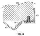
- the exit pressure seal is shown in Figure 6.
- the belt side of the aluminum slat is coated with 127 ⁇ m (5 mil) PTFE (Teflon®) fiberglass cloth 900, which extends beyond the end of the aluminum seal and mounts to the inside of the pressure box frame.
- This exit seal design keeps the drive belt from binding on the aluminum slat.
- these metal seals are replaced with one or more bladders, in particular inflatable rubber bladders, which offer several, advantages not provided by the above-described metal seals.
- Figures 7A, 7B and 7C depict the positioning of one inflatable bladder 200 (e.g., silicone rubber) on the peripheral edges of the pressure box (Fig. 7A); the bladder 200 as inflated with the Teflon® coated metal slip plate 210 (Fig. 7B); and the bladder 200 as partially deformed via belt contact (Fig. 7C) creating the desired seal for the pressure box.
- a channel 220 is provided in the frame of the pressure box wall for attachment of the rubber bladder (Fig. 7C).
- An inflatable bladder of this type can be used for both the upper and the lower portions of the pressure box.
- this invention may be used to manufacture non-woven fabrics using the preferred pressure lamination apparatus.
- PCT Publication No. WO 00/41523 describes a non-woven warp yarn fabric material, which is one preferred substrate for lamination in the present invention.
- the PCT Publication describes one preferred substrate for use in the pressure laminator of the present invention.
- the substrate of the PCT Publication comprises a plurality of yarns that are formed into an aligned group, substantially parallel and equally spaced apart, and held together by a hot melt adhesive applied to one side of the fiber group.
- This fiber orientation in which the fibers run in the machine direction, creates a non-woven fabric material substrate in which the fibers mimic warp yarns, which can be combined with one or more woven or non-woven fiber substrates and pressure laminated to create finished products that have the visual impression and physical feel of a woven material.
- PCT Publication No. WO 00/41523 also describes the formation of a preferred substrate material used in the pressure laminator of the present invention.
- the PCT Publication describes an apparatus for fabricating a non-woven fabric composite, which has the appearance of a woven fabric.
- the apparatus includes a supply station for adhesive coated parallel warp yarns, a support structure for orienting the parallel warp yarns into a cylindrical orientation with the adhesive film on the outside, a weft yarn applicator for wrapping weft yarns around the cylindrically oriented warp yarns, a heating station for activating the adhesive and a cooling station for setting the adhesive, and a cutter for severing the cylindrically formed fabric composite so that it can be flattened and wrapped onto a take-up roller, for transfer to the pressure laminator of the present invention.
- the weft yarn applicator disclosed in the PCT Publication includes a rotating drum wherein a plurality of spools of weft yarn material are mounted in circumferentially spaced relationship and a tensioner is provided for applying the weft yarn material around the warp yarns in a predetermined tension which may be the same as, greater than, or less than the tension in the warp yarns.
- a conical aligner assures that the weft yarns will be delivered to the warp yarn cylinder in substantially perpendicular alignment.
Landscapes
- Engineering & Computer Science (AREA)
- Textile Engineering (AREA)
- General Chemical & Material Sciences (AREA)
- Fluid Mechanics (AREA)
- Chemical & Material Sciences (AREA)
- Chemical Kinetics & Catalysis (AREA)
- Physics & Mathematics (AREA)
- Laminated Bodies (AREA)
- Lining Or Joining Of Plastics Or The Like (AREA)
- Casting Or Compression Moulding Of Plastics Or The Like (AREA)
- Nonwoven Fabrics (AREA)
- Encapsulation Of And Coatings For Semiconductor Or Solid State Devices (AREA)
- Press Drives And Press Lines (AREA)
- Production Of Multi-Layered Print Wiring Board (AREA)
- Devices For Conveying Motion By Means Of Endless Flexible Members (AREA)
Claims (29)
- Doppelbandpresse (400) umfassend:- ein Gehäuse oder einen Rahmen;- eine Druckkammer (401), die in dem Gehäuse oder Rahmen befestigt ist und einen oberen und einen unteren, jeweils mit Druck beaufschlagbaren Abschnitt (412, 414) umfaßt, wobei ein zwischen den beiden Abschnitten gebildeter Raum einen Laminierungsabschnitt bildet;- gegenläufig rotierende obere und untere Bänder (402, 404), die drehbar im Gehäuse oder Rahmen befestigt sind und sich im Laminierungsabschnitt berühren und in derselben Richtung durch den Laminierungsabschnitt laufen; und- einen Fluid-Druckerzeuger (602, 604), der den oberen und den unteren Abschnitt (412, 414) der Druckkammer (401) mit Druck versorgt, um die Bänder (402, 404), die sich dazwischen bewegen, zusammenzudrücken;- wobei, abhängig von der Drehrichtung der Bänder (402, 404) ein Ende (416) des Laminierungsabschnitts als Einführung für Substrate dient, die im Laminierungsabschnitt zwischen den Bändern unter Druck zu laminieren sind, und ein gegenüberliegendes Ende (418) als Auslaß für drucklaminierte Substrate dient; und- wobei der obere Abschnitt (412) der Druckkammer an den Seiten und den Einführungs- und Auslaßenden (416, 418) Druckdichtungen (200) umfaßt, dadurch gekennzeichnet, daß die Druckdichtungen Bälge (200) umfassen.
- Vorrichtung gemäß Anspruch 1, bei der jeder Balg einen Gummibalg (200) umfaßt.
- Vorrichtung gemäß Anspruch 1 oder 2, bei der jeder Balg (200) aufblasbar ist.
- Vorrichtung gemäß einem der Ansprüche 1 bis 4, bei der zwischen jedem Balg (200) und einem der Bänder (402, 404) eine mit Teflon beschichtete Metall-Gleitplatte (210) vorgesehen ist.
- Vorrichtung gemäß einem der Ansprüche 1 bis 4, bei der der untere Abschnitt (414) der Druckkammer ebenfalls Druckdichtungen (200) an den Seiten und den Einführungs- und Auslaßenden (416, 418) umfaßt.
- Vorrichtung gemäß einem der Ansprüche 1 bis 5, bei der Heiz- und Kühlelemente (310A, 310B usw. und 320A, 320B usw.) innerhalb des oberen und des unteren Abschnitts (412, 414) der Druckkammer (401) vorgesehen sind.
- Vorrichtung gemäß Anspruch 6, bei der ein Heizelement (310B, 310D usw.) innerhalb des oberen Abschnitts (412) der Druckkammer (401) angeordnet ist.
- Vorrichtung gemäß Anspruch 7, bei der das Heizelement (310B, 310D usw.) im oberen Abschnitt mehrere Heizelemente, eine dampfbetriebene Heizstrecke oder Infrarotheizung umfaßt.
- Vorrichtung gemäß Anspruch 6, bei der ein Kühlelement (320B, 320D usw.) innerhalb des oberen Abschnitts (412) der Druckkammer angeordnet ist.
- Vorrichtung gemäß Anspruch 9, bei der das Kühlelement (320B, 320D usw.) im oberen Abschnitt mehrere Kühlelemente umfaßt.
- Vorrichtung gemäß Anspruch 9, bei der das Kühlelement im oberen Abschnitt eine Kaltwasser-Kühlstrecke umfaßt.
- Vorrichtung gemäß einem der Ansprüche 7 bis 11, bei der Heiz- und Kühlelemente innerhalb des oberen Abschnitts der Druckkammer angeordnet sind.
- Vorrichtung gemäß einem der Ansprüche 6 bis 12, bei der ein Heizelement (310A, 310C usw.) innerhalb des unteren Abschnitts (414) der Druckkammer (401) angeordnet ist.
- Vorrichtung gemäß Anspruch 14, bei der das Heizelement im unteren Abschnitt der Druckkammer mehrere Heizelemente, eine dampfbetriebene Heizstrecke oder Infrarotheizung umfaßt.
- Vorrichtung gemäß einem der Ansprüche 6 bis 12, bei der ein Kühlelement (320A, 320C usw.) innerhalb des unteren Abschnitts der Druckkammer angeordnet ist.
- Vorrichtung gemäß Anspruch 15, bei der das Kühlelement im unteren Abschnitt der Druckkammer mehrere Kühlelemente umfaßt.
- Vorrichtung gemäß Anspruch 15, bei der das Kühlelement im unteren Abschnitt der Druckkammer eine Kaltwasser-Kühlstrecke umfaßt.
- Vorrichtung gemäß Anspruch 16, bei der die mehreren Kühlelemente im unteren Abschnitt der Druckkammer ortsfest sind.
- Vorrichtung gemäß einem der Ansprüche 16 bis 20, bei der Heiz- und Kühlelemente innerhalb des unteren Abschnitts der Druckkammer angeordnet sind.
- Vorrichtung gemäß einem der Ansprüche 7 bis 12, bei der die Heiz- und Kühlelemente im oberen Abschnitt der Druckkammer so montiert sind, daß sie frei auf dem oberen Band aufliegen.
- Vorrichtung gemäß Anspruch 13 oder 14, bei der die Heizelemente im unteren Abschnitt der Druckkammer ortsfest sind.
- Vorrichtung gemäß einem der Ansprüche 7 bis 21, bei der die Heiz- und Kühlelemente versetzt angeordnet sind.
- Vorrichtung gemäß einem der Ansprüche 1 bis 22, bei der der untere Abschnitt (414) der Druckkammer starr an dem Gehäuse oder Rahmen befestigt ist.
- Vorrichtung gemäß einem der Ansprüche 1 bis 23, bei der der obere Abschnitt (412) der Druckkammer verstellbar an dem Gehäuse oder Rahmen befestigt ist.
- Vorrichtung gemäß einem der Ansprüche 1 bis 24, bei der die Bänder (402, 404) auf einer Fläche von etwa 967.740 mm2 (1.500 Quadratzoll) mit einem Druck im Bereich von etwa 2.268 kg (5.000 lbs) bis etwa 22.680 kg (50.000 lbs) beaufschlagt werden.
- Vorrichtung gemäß Anspruch 25, bei der die Bänder (402, 404) auf einer Fläche von etwa 967.740 mm2 (1.500 Quadratzoll) mit einem Druck im Bereich von etwa 4.536 kg (10.000 lbs) bis etwa 11.340 kg (25.000 lbs) beaufschlagt werden.
- Vorrichtung gemäß einem der Ansprüche 1 bis 26, weiter umfassend ein Ausrichtungssystem mit einem elektrischen Auge, einem Ausrichtungs-Servomotor und einem Ausrichtungsschlitten, wobei das elektrische Auge dafür vorgesehen ist zu erkennen, wenn sich eins der Antriebsbänder von der korrekten Ausrichtung entfernt, und in der Lage ist, den Ausrichtungs-Servomotor anzusteuern, so daß die Antriebsbänder durch seitliche Bewegung des Ausrichtungsschlittens nachgestellt werden.
- Vorrichtung gemäß einem der Ansprüche 1 bis 27, bei der der Fluid-Druckerzeuger (602, 604) Luft, Dampf, Wasser oder Öl verwendet.
- Vorrichtung gemäß Anspruch 28, bei der ein Drucklufterzeuger den oberen und den unteren Abschnitt (412, 414) der Druckkammer mit Druck versorgt, um die Bänder (402, 404) zusammenzupressen.
Applications Claiming Priority (3)
| Application Number | Priority Date | Filing Date | Title |
|---|---|---|---|
| US15536499P | 1999-09-20 | 1999-09-20 | |
| US155364P | 1999-09-20 | ||
| PCT/US2000/025680 WO2001021399A1 (en) | 1999-09-20 | 2000-09-20 | Pressure laminator apparatus and non-woven fabric formed thereby |
Publications (2)
| Publication Number | Publication Date |
|---|---|
| EP1274580A1 EP1274580A1 (de) | 2003-01-15 |
| EP1274580B1 true EP1274580B1 (de) | 2006-02-08 |
Family
ID=22555151
Family Applications (1)
| Application Number | Title | Priority Date | Filing Date |
|---|---|---|---|
| EP00963628A Expired - Lifetime EP1274580B1 (de) | 1999-09-20 | 2000-09-20 | Doppelbandpresse |
Country Status (9)
| Country | Link |
|---|---|
| EP (1) | EP1274580B1 (de) |
| JP (1) | JP4471549B2 (de) |
| AT (1) | ATE317328T1 (de) |
| AU (1) | AU773064B2 (de) |
| CA (1) | CA2384370C (de) |
| DE (1) | DE60025930T2 (de) |
| DK (1) | DK1274580T3 (de) |
| ES (1) | ES2253252T3 (de) |
| WO (1) | WO2001021399A1 (de) |
Cited By (1)
| Publication number | Priority date | Publication date | Assignee | Title |
|---|---|---|---|---|
| KR101320797B1 (ko) * | 2013-05-14 | 2013-10-23 | 박태근 | 폴리에스테르 고탄성 쿠션재 제조용 드라이 오븐 |
Families Citing this family (13)
| Publication number | Priority date | Publication date | Assignee | Title |
|---|---|---|---|---|
| US7056403B2 (en) | 1999-01-12 | 2006-06-06 | Hunter Douglas Inc. | Apparatus for producing non-woven fabric |
| US6883213B2 (en) | 1999-01-12 | 2005-04-26 | Hunter Douglas Inc. | Apparatus for producing non-woven fabric |
| KR100694366B1 (ko) | 1999-01-12 | 2007-03-12 | 헌터 더글라스 인더스트리즈 비 브이 | 부직물 및 이의 제조방법과 장치 |
| US6805771B1 (en) | 1999-09-20 | 2004-10-19 | Hunter Douglas Industries B.V. | Pressure laminator apparatus and non woven fabric formed thereby |
| US7090743B2 (en) | 1999-09-20 | 2006-08-15 | Hunter Douglas Inc. | Pressure laminator apparatus |
| US6926055B1 (en) | 1999-09-20 | 2005-08-09 | Hunter Douglas Inc. | Non-woven composite fabric and method and apparatus for manufacturing same |
| US7017244B2 (en) | 2002-06-03 | 2006-03-28 | Hunter Douglas Inc. | Beam winding apparatus |
| DE102005055855B4 (de) | 2005-11-23 | 2018-08-02 | Hymmen GmbH Maschinen- und Anlagenbau | Druckzone einer Doppelbandpresse |
| DE102009020172A1 (de) * | 2009-05-07 | 2010-11-11 | Robert Bürkle GmbH | Presse zum Laminieren von im Wesentlichen plattenförmigen Werkstücken |
| DE102009035633A1 (de) * | 2009-07-31 | 2011-02-03 | Robert Bürkle GmbH | Presse und Verfahren zum Ein- und Ausfördern von Werkstücken in die und aus der Presse |
| ITUA20161363A1 (it) * | 2016-03-04 | 2017-09-04 | System Spa | Dispositivo di pressatura |
| CN109399306A (zh) * | 2018-09-29 | 2019-03-01 | 芜湖华烨工业用布有限公司 | 一种工业用布收卷设备 |
| CN112428656A (zh) * | 2020-11-30 | 2021-03-02 | 枣庄佳莱堡新材料科技有限公司 | 一种耐磨型三聚氰胺浸胶纸压贴生产装置 |
Family Cites Families (12)
| Publication number | Priority date | Publication date | Assignee | Title |
|---|---|---|---|---|
| US3591434A (en) * | 1967-08-21 | 1971-07-06 | Swirltex Inc | Bi-axial laminated non-woven fabric and method of manufacture |
| DE3046431A1 (de) * | 1980-12-10 | 1982-09-09 | Santrade Ltd., 6002 Luzern | Doppelbandpresse |
| DE3046432C2 (de) * | 1980-12-10 | 1983-02-24 | Santrade Ltd., 6002 Luzern | Doppelbandpresse |
| US4498941A (en) * | 1981-08-05 | 1985-02-12 | Goldsworthy Engineering, Inc. | Method for producing fiber reinforced sheet structures |
| DE3515629A1 (de) * | 1985-05-02 | 1986-11-06 | Held, Kurt, 7218 Trossingen | Verfahren und vorrichtung zur herstellung kupferkaschierter laminate |
| US4794855A (en) * | 1986-08-05 | 1989-01-03 | Mitsubishi Rayon Engineering Co., Ltd. | Continuous press machine |
| JPS63267525A (ja) * | 1987-04-25 | 1988-11-04 | Mitsubishi Rayon Eng Co Ltd | 連続加圧装置 |
| DE3719976A1 (de) * | 1987-06-15 | 1988-12-29 | Hymmen Theodor Gmbh | Verfahren und vorrichtung zum aufbringen einer flaechenpressung auf pressbandgetriebene werkstuecke |
| JPH01210318A (ja) * | 1988-02-19 | 1989-08-23 | Mitsubishi Rayon Eng Co Ltd | 連続加圧装置 |
| US5352321A (en) * | 1989-06-29 | 1994-10-04 | Kurt Held | Continuously operating double band press |
| CA2045987A1 (en) * | 1990-08-06 | 1992-02-07 | Haruhiko Maki | Continuous production of metal clad laminates |
| KR100694366B1 (ko) * | 1999-01-12 | 2007-03-12 | 헌터 더글라스 인더스트리즈 비 브이 | 부직물 및 이의 제조방법과 장치 |
-
2000
- 2000-09-20 EP EP00963628A patent/EP1274580B1/de not_active Expired - Lifetime
- 2000-09-20 JP JP2001524803A patent/JP4471549B2/ja not_active Expired - Lifetime
- 2000-09-20 CA CA002384370A patent/CA2384370C/en not_active Expired - Fee Related
- 2000-09-20 DE DE60025930T patent/DE60025930T2/de not_active Expired - Lifetime
- 2000-09-20 DK DK00963628T patent/DK1274580T3/da active
- 2000-09-20 AU AU38869/01A patent/AU773064B2/en not_active Ceased
- 2000-09-20 ES ES00963628T patent/ES2253252T3/es not_active Expired - Lifetime
- 2000-09-20 WO PCT/US2000/025680 patent/WO2001021399A1/en not_active Ceased
- 2000-09-20 AT AT00963628T patent/ATE317328T1/de not_active IP Right Cessation
Cited By (1)
| Publication number | Priority date | Publication date | Assignee | Title |
|---|---|---|---|---|
| KR101320797B1 (ko) * | 2013-05-14 | 2013-10-23 | 박태근 | 폴리에스테르 고탄성 쿠션재 제조용 드라이 오븐 |
Also Published As
| Publication number | Publication date |
|---|---|
| DK1274580T3 (da) | 2006-06-12 |
| DE60025930T2 (de) | 2006-08-03 |
| EP1274580A1 (de) | 2003-01-15 |
| AU773064B2 (en) | 2004-05-13 |
| CA2384370C (en) | 2009-03-10 |
| JP2003509599A (ja) | 2003-03-11 |
| ES2253252T3 (es) | 2006-06-01 |
| ATE317328T1 (de) | 2006-02-15 |
| CA2384370A1 (en) | 2001-03-29 |
| WO2001021399A1 (en) | 2001-03-29 |
| AU3886901A (en) | 2001-04-24 |
| DE60025930D1 (de) | 2006-04-20 |
| JP4471549B2 (ja) | 2010-06-02 |
Similar Documents
| Publication | Publication Date | Title |
|---|---|---|
| EP1274580B1 (de) | Doppelbandpresse | |
| KR100694366B1 (ko) | 부직물 및 이의 제조방법과 장치 | |
| US6805771B1 (en) | Pressure laminator apparatus and non woven fabric formed thereby | |
| CA2385957C (en) | Method of making a cut and abrasion resistant laminate | |
| US7090743B2 (en) | Pressure laminator apparatus | |
| US6294036B1 (en) | Method and device for making composite sheets | |
| US3547742A (en) | Laminator apparatus | |
| CA1245141A (en) | Joining tape and process therefor | |
| EP0733477B1 (de) | Verfahren zum Formen von Materialien für Polsterteile | |
| AU2003259657B2 (en) | Nonwoven fabric and method and apparatus for manufacturing same | |
| AU2006220362B2 (en) | Nonwoven fabric and method and apparatus for manufacturing same | |
| KR102114001B1 (ko) | 복합섬유 제직장치 | |
| JP3667932B2 (ja) | 繊維強化シートの製造方法及び製造装置 | |
| CA2615794C (en) | Nonwoven fabric and method and apparatus for manufacturing same | |
| HK1037698B (en) | Nonwoven fabric |
Legal Events
| Date | Code | Title | Description |
|---|---|---|---|
| PUAI | Public reference made under article 153(3) epc to a published international application that has entered the european phase |
Free format text: ORIGINAL CODE: 0009012 |
|
| 17P | Request for examination filed |
Effective date: 20020321 |
|
| AK | Designated contracting states |
Kind code of ref document: A1 Designated state(s): AT BE CH CY DE DK ES FI FR GB GR IE IT LI LU MC NL PT SE |
|
| 17Q | First examination report despatched |
Effective date: 20041104 |
|
| RIN1 | Information on inventor provided before grant (corrected) |
Inventor name: DANN, KEVIN Inventor name: COLSON, WENDELL, B. |
|
| RAP1 | Party data changed (applicant data changed or rights of an application transferred) |
Owner name: HUNTER DOUGLAS INC. |
|
| GRAP | Despatch of communication of intention to grant a patent |
Free format text: ORIGINAL CODE: EPIDOSNIGR1 |
|
| RTI1 | Title (correction) |
Free format text: PRESSURE LAMINATOR APPARATUS |
|
| GRAS | Grant fee paid |
Free format text: ORIGINAL CODE: EPIDOSNIGR3 |
|
| GRAA | (expected) grant |
Free format text: ORIGINAL CODE: 0009210 |
|
| RIC1 | Information provided on ipc code assigned before grant |
Ipc: B32B 37/00 20060101AFI20051213BHEP Ipc: D04H 3/04 20060101ALI20051213BHEP Ipc: B30B 5/06 20060101ALI20051213BHEP |
|
| AK | Designated contracting states |
Kind code of ref document: B1 Designated state(s): AT BE CH CY DE DK ES FI FR GB GR IE IT LI LU MC NL PT SE |
|
| PG25 | Lapsed in a contracting state [announced via postgrant information from national office to epo] |
Ref country code: FI Free format text: LAPSE BECAUSE OF FAILURE TO SUBMIT A TRANSLATION OF THE DESCRIPTION OR TO PAY THE FEE WITHIN THE PRESCRIBED TIME-LIMIT Effective date: 20060208 Ref country code: AT Free format text: LAPSE BECAUSE OF FAILURE TO SUBMIT A TRANSLATION OF THE DESCRIPTION OR TO PAY THE FEE WITHIN THE PRESCRIBED TIME-LIMIT Effective date: 20060208 |
|
| REG | Reference to a national code |
Ref country code: GB Ref legal event code: FG4D |
|
| REG | Reference to a national code |
Ref country code: CH Ref legal event code: EP |
|
| REG | Reference to a national code |
Ref country code: IE Ref legal event code: FG4D |
|
| REF | Corresponds to: |
Ref document number: 60025930 Country of ref document: DE Date of ref document: 20060420 Kind code of ref document: P |
|
| REG | Reference to a national code |
Ref country code: CH Ref legal event code: NV Representative=s name: ROTTMANN, ZIMMERMANN + PARTNER AG |
|
| REG | Reference to a national code |
Ref country code: SE Ref legal event code: TRGR |
|
| REG | Reference to a national code |
Ref country code: ES Ref legal event code: FG2A Ref document number: 2253252 Country of ref document: ES Kind code of ref document: T3 |
|
| REG | Reference to a national code |
Ref country code: DK Ref legal event code: T3 |
|
| PG25 | Lapsed in a contracting state [announced via postgrant information from national office to epo] |
Ref country code: PT Free format text: LAPSE BECAUSE OF FAILURE TO SUBMIT A TRANSLATION OF THE DESCRIPTION OR TO PAY THE FEE WITHIN THE PRESCRIBED TIME-LIMIT Effective date: 20060710 |
|
| PG25 | Lapsed in a contracting state [announced via postgrant information from national office to epo] |
Ref country code: IE Free format text: LAPSE BECAUSE OF NON-PAYMENT OF DUE FEES Effective date: 20060920 |
|
| ET | Fr: translation filed | ||
| PG25 | Lapsed in a contracting state [announced via postgrant information from national office to epo] |
Ref country code: MC Free format text: LAPSE BECAUSE OF NON-PAYMENT OF DUE FEES Effective date: 20060930 |
|
| PLBE | No opposition filed within time limit |
Free format text: ORIGINAL CODE: 0009261 |
|
| STAA | Information on the status of an ep patent application or granted ep patent |
Free format text: STATUS: NO OPPOSITION FILED WITHIN TIME LIMIT |
|
| 26N | No opposition filed |
Effective date: 20061109 |
|
| PG25 | Lapsed in a contracting state [announced via postgrant information from national office to epo] |
Ref country code: GR Free format text: LAPSE BECAUSE OF FAILURE TO SUBMIT A TRANSLATION OF THE DESCRIPTION OR TO PAY THE FEE WITHIN THE PRESCRIBED TIME-LIMIT Effective date: 20060509 |
|
| PG25 | Lapsed in a contracting state [announced via postgrant information from national office to epo] |
Ref country code: LU Free format text: LAPSE BECAUSE OF NON-PAYMENT OF DUE FEES Effective date: 20060920 |
|
| PG25 | Lapsed in a contracting state [announced via postgrant information from national office to epo] |
Ref country code: CY Free format text: LAPSE BECAUSE OF FAILURE TO SUBMIT A TRANSLATION OF THE DESCRIPTION OR TO PAY THE FEE WITHIN THE PRESCRIBED TIME-LIMIT Effective date: 20060208 |
|
| PGFP | Annual fee paid to national office [announced via postgrant information from national office to epo] |
Ref country code: DK Payment date: 20090914 Year of fee payment: 10 |
|
| PGFP | Annual fee paid to national office [announced via postgrant information from national office to epo] |
Ref country code: SE Payment date: 20090910 Year of fee payment: 10 Ref country code: NL Payment date: 20090903 Year of fee payment: 10 Ref country code: GB Payment date: 20090916 Year of fee payment: 10 |
|
| PGFP | Annual fee paid to national office [announced via postgrant information from national office to epo] |
Ref country code: ES Payment date: 20091006 Year of fee payment: 10 Ref country code: CH Payment date: 20091006 Year of fee payment: 10 |
|
| PGFP | Annual fee paid to national office [announced via postgrant information from national office to epo] |
Ref country code: BE Payment date: 20090917 Year of fee payment: 10 |
|
| PGFP | Annual fee paid to national office [announced via postgrant information from national office to epo] |
Ref country code: FR Payment date: 20091012 Year of fee payment: 10 Ref country code: IT Payment date: 20090912 Year of fee payment: 10 |
|
| BERE | Be: lapsed |
Owner name: *HUNTER DOUGLAS INC. Effective date: 20100930 |
|
| REG | Reference to a national code |
Ref country code: NL Ref legal event code: V1 Effective date: 20110401 |
|
| REG | Reference to a national code |
Ref country code: CH Ref legal event code: PL |
|
| REG | Reference to a national code |
Ref country code: SE Ref legal event code: EUG |
|
| GBPC | Gb: european patent ceased through non-payment of renewal fee |
Effective date: 20100920 |
|
| REG | Reference to a national code |
Ref country code: DK Ref legal event code: EBP |
|
| PG25 | Lapsed in a contracting state [announced via postgrant information from national office to epo] |
Ref country code: IT Free format text: LAPSE BECAUSE OF NON-PAYMENT OF DUE FEES Effective date: 20100920 |
|
| REG | Reference to a national code |
Ref country code: FR Ref legal event code: ST Effective date: 20110531 |
|
| PG25 | Lapsed in a contracting state [announced via postgrant information from national office to epo] |
Ref country code: BE Free format text: LAPSE BECAUSE OF NON-PAYMENT OF DUE FEES Effective date: 20100930 Ref country code: LI Free format text: LAPSE BECAUSE OF NON-PAYMENT OF DUE FEES Effective date: 20100930 Ref country code: CH Free format text: LAPSE BECAUSE OF NON-PAYMENT OF DUE FEES Effective date: 20100930 Ref country code: FR Free format text: LAPSE BECAUSE OF NON-PAYMENT OF DUE FEES Effective date: 20100930 |
|
| PG25 | Lapsed in a contracting state [announced via postgrant information from national office to epo] |
Ref country code: GB Free format text: LAPSE BECAUSE OF NON-PAYMENT OF DUE FEES Effective date: 20100920 Ref country code: NL Free format text: LAPSE BECAUSE OF NON-PAYMENT OF DUE FEES Effective date: 20110401 |
|
| REG | Reference to a national code |
Ref country code: ES Ref legal event code: FD2A Effective date: 20111019 |
|
| PG25 | Lapsed in a contracting state [announced via postgrant information from national office to epo] |
Ref country code: DK Free format text: LAPSE BECAUSE OF NON-PAYMENT OF DUE FEES Effective date: 20100930 |
|
| PG25 | Lapsed in a contracting state [announced via postgrant information from national office to epo] |
Ref country code: ES Free format text: LAPSE BECAUSE OF NON-PAYMENT OF DUE FEES Effective date: 20100921 |
|
| PG25 | Lapsed in a contracting state [announced via postgrant information from national office to epo] |
Ref country code: SE Free format text: LAPSE BECAUSE OF NON-PAYMENT OF DUE FEES Effective date: 20100921 |
|
| PGFP | Annual fee paid to national office [announced via postgrant information from national office to epo] |
Ref country code: DE Payment date: 20190910 Year of fee payment: 20 |
|
| REG | Reference to a national code |
Ref country code: DE Ref legal event code: R071 Ref document number: 60025930 Country of ref document: DE |