EP1274108A1 - Pôle de disjoncteur à gaz sous pression pouvant être assemblé et désassemblé sans perte de gaz appréciable - Google Patents
Pôle de disjoncteur à gaz sous pression pouvant être assemblé et désassemblé sans perte de gaz appréciable Download PDFInfo
- Publication number
- EP1274108A1 EP1274108A1 EP02291557A EP02291557A EP1274108A1 EP 1274108 A1 EP1274108 A1 EP 1274108A1 EP 02291557 A EP02291557 A EP 02291557A EP 02291557 A EP02291557 A EP 02291557A EP 1274108 A1 EP1274108 A1 EP 1274108A1
- Authority
- EP
- European Patent Office
- Prior art keywords
- assembly
- enclosure
- flange
- seal
- circuit breaker
- Prior art date
- Legal status (The legal status is an assumption and is not a legal conclusion. Google has not performed a legal analysis and makes no representation as to the accuracy of the status listed.)
- Withdrawn
Links
Images



Classifications
-
- H—ELECTRICITY
- H01—ELECTRIC ELEMENTS
- H01H—ELECTRIC SWITCHES; RELAYS; SELECTORS; EMERGENCY PROTECTIVE DEVICES
- H01H33/00—High-tension or heavy-current switches with arc-extinguishing or arc-preventing means
- H01H33/02—Details
- H01H33/53—Cases; Reservoirs, tanks, piping or valves, for arc-extinguishing fluid; Accessories therefor, e.g. safety arrangements, pressure relief devices
- H01H33/56—Gas reservoirs
- H01H33/561—Gas reservoirs composed of different independent pressurised compartments put in communication only after their assemblage
Definitions
- the present invention relates to a gas circuit breaker pole under pressure can be assembled and disassembled without loss of gas appreciable and comprising a first enclosure called pole head comprising a first envelope comprising a first flange of connection having a circular orifice, said envelope containing a first moving part ending in a coupling member, coaxial with said audit orifice, and a second enclosure constituting an insulating column comprising a second envelope comprising a second connecting flange comprising a circular orifice, said second envelope containing a second mobile assembly consisting of an operating rod of said first mobile assembly and its end comprising complementary means coupling with said coupling member.
- the poles of large circuit breakers and in particular the T-poles with two interrupting chambers in series, cannot be routed to their place of installation all assembled: the head of the pole on the one hand, constituting a first enclosure containing all the active, fixed and mobile of the two breaking chambers, and the insulating column on the other hand containing the connecting rod for moving parts of the circuit breaker pole, are therefore transported disassembled and are only assembled on the site.
- this operation must be done in the factory for each of the two parts of the pole: pole head and insulating column.
- the void is made, we fill the two parts in dielectric gas with an overpressure of the order of 0.3 bar and it is in this state that the parts are transported to the site. A once the assembly is completed, the gas pressure in the pole is brought to its nominal value.
- the document FR-A1-2 568 405 describes a circuit breaker in which the head of each pole has a sliding airlock and the column a chimney, allowing coupling and uncoupling with low loss of gas corresponding to the combined volume of the airlock and the chimney.
- this arrangement requires several additional rooms including the airlock sliding and a sliding sleeve, as well as one end particular in "chimney" of the column.
- an overtravel of the moving parts of the pole, beyond the closed position of the circuit breaker must be planned.
- Document FR 2 415 358 A describes a circuit breaker which allows, thanks to an inflatable seal, to ensure the transport of the insulator support before its assembly with the upper part having previously vacuumed then fills the insulator support with gas.
- nothing is planned for the game upper and, on the other hand, it is necessary to deflate the seal of the insulating column after assembly.
- the present invention aims to provide a simplified solution requiring only a few parts, allowing assembly and disassembly fast and requiring no other operation than that of assembly and pressurizing the pole with dielectric gas at nominal value, the gas communication between the two speakers being automatic and requiring no additional operation.
- the invention thus relates to a gas circuit breaker pole under pressure can be assembled and disassembled without loss of gas appreciable and comprising a first enclosure called pole head comprising a first envelope comprising a first flange of connection having a circular orifice, said envelope containing a first moving part ending in a coupling member, coaxial with said audit orifice, and a second enclosure constituting an insulating column comprising a second envelope comprising a second connecting flange having a circular orifice, said second envelope containing a second crew mobile consisting of an operating rod of said first mobile assembly and its end comprising complementary coupling means with said coupling member, characterized in that the connecting flange of each enclosure is equipped with an annular elastomer seal, fixed to the corresponding connecting flange crossed by the moving element corresponding, said seal of each enclosure ensuring, for the assembly of the flanges and the coupling of the internal moving parts, sliding sealing along the respective moving assembly and means being provided to break the seal along said crews mobile at the end of assembly
- said seals Annular elastomers are tiltable deformable seals.
- a said tiltable deformable joint comprises a external anchoring ring connected by an isthmus to a joint body comprising a heel and a lip, the heel of each joint extending beyond the outer plane of the corresponding flange.
- said means for break the seal along said moving parts have a drawer sliding whose axial length is greater than the distance separating the two annular elastomer seals in the assembled position of the first and of the second envelope.
- a so-called elastomeric seal annular comprises a first peripheral part taken between a flange and a counter flange, a second part constituting a hollow ring deformable with walls with more flexible parts and others more rigid, and a third central part constituting a simple disc of weak thickness ensuring sliding sealing along the moving assembly.
- a circuit breaker pole before its assembly and comprising a first enclosure constituting the pole head 1 comprising a first envelope 2 containing a first moving part 3 to which the active moving parts not linked represented by the circuit breaker.
- the moving equipment 3 ends with a member coupling 4 coaxial to a circular orifice 5 of the envelope made in a first connecting flange 6 attached and fixed by screws 7 to a base 8 having an opening 9 coaxial with the orifice 5.
- the first connecting flange 6 is equipped with an elastomer seal annular 10 ensuring a sliding seal along the crew mobile 3, between the inside of the envelope 2 and the outside.
- the pole head 1 Before assembly, the pole head 1 is closed by a cover 11 fixed by screws 12 with interposition of a seal 36. This cover protects the assembly member 4.
- a vacuum is created in the pole head and then it is filled with a gas dielectric at an overpressure of about 0.3 bar.
- pole head 1 On site, pole head 1 must be assembled within one second enclosure 13 also filled with a dielectric gas.
- the second casing 14 has a second connecting flange 17 fixed by screws 18 to a base 19 of the casing 14.
- the second connecting flange 17 provided with a circular orifice 20 is fitted with an annular elastomeric seal 21 identical to seal 10 and ensuring a sliding seal along the connecting rod 15, between the interior of the column 13 and the outside.
- the column 13 is provided, before its assembly with the head, of a protective cover 22 of the means assembly 16, by means of screws 23 with interposition of a seal 37.
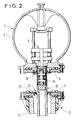
- the assembly member 4 is surrounded by a sliding jacket 24 ensuring continuity and equality of diameter once the moving parts carried out as shown in fig. 2 where, the covers 11 and 22 having been removed, the two moving parts 3 and 15 were coupled, then the sleeve 24 has been slid downwards thus covering the organs mating of a smooth surface.
- a seal 25 is placed on the flange 17.
- the pole head 1 is lowered so as to assemble the two flanges 6 and 17 with screws 26 as seen in fig. 3.
- the seal 21 slides along the connecting rod 15 and the jacket 24.
- seals 10 and 21 deform and lose contact with the crew mobile 15-24, thus ensuring gas communication between the two enclosures 1 and 13.
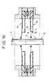
- the seals 10 and 21, as can be seen on the Fig. 4 enlarged, are deformable seals each comprising a ring external anchoring 26, 27 connected by an isthmus 28, 29 to a joint body 30, 31, comprising a lip 32, 33, and a heel 34, 35.
- the heels 34, 35 protrude from the outside plane of the respective flanges 6, 17 so that during the assembly of the flanges, the heels 34 and 35 meet making tilt the seal body 30, 31 around the isthmus 28, 29.
- the coupling and uncoupling of the head 1 and column 13 are made by ensuring the respective tightness of the two parts and therefore without losing gas while at the end of mating, the communication is established between the two speakers and this automatically without any additional operation.
- the assembly finished, the pole is filled with dielectric gas at its nominal pressure.
- Figs. 5 and 6 show a second embodiment of the invention.
- the casing 2 of the head 1 comprises a flange 44 having a circular opening 45, the flange being fitted with a seal annular elastomer 46 which is a simple flat disc-like seal attached by a counter flange 47.
- the seal 46 surrounds the sliding sleeve 24.
- the flange 17 of the casing 14 is equipped with a seal identical 48.
- the flange 17 is equipped, outside of the enclosure 13, with respect to the seal 48, of a sliding drawer 49 the length of which axial is greater than the distance separating the two seals 46, 48 in position assembly of the two enclosures when the two flanges 44 and 17 are at contact with each other, as shown in fig. 6 where we see that the two ends of the drawer 49 come into contact with the seals 46, 48 causing the rupture of the seal and thus ensuring communication between the two speakers 1 and 13.
- Figs. 7 to 10 show very schematically a third example for implementing the invention.
- the seals each have a first peripheral part 55, 56 taken between a flange and a counter flange, respectively 57, 58 and 59, 60, a second part 61, 62 constituting a deformable hollow ring comprising walls of which certain parts such as 63, 64, 65, 66 are more flexible and others 67, 68, 69, 70 are more rigid, and finally a third central part 71, 72 constituting a simple weak disc thickness ensuring sliding sealing along the moving parts 3, 15.
- the central part 71, 72 possibly includes a terminal bulge ring finger 73, 74.
- the separate chambers 1 and 13 are filled with dielectric gas under a slight overpressure of around 0.3 bar. Once the assembly is completed, we continues filling with dielectric gas until pressure is obtained rated service. In the case of this third exemplary embodiment, it is this operation which makes it possible to "break" the tightness of the joints 53 and 54 to allow communication between the two speakers 1 and 13.
Landscapes
- Gas-Insulated Switchgears (AREA)
- Gasket Seals (AREA)
- Driving Mechanisms And Operating Circuits Of Arc-Extinguishing High-Tension Switches (AREA)
- Circuit Breakers (AREA)
- Arc-Extinguishing Devices That Are Switches (AREA)
- High-Tension Arc-Extinguishing Switches Without Spraying Means (AREA)
Abstract
Description
Claims (5)
- Pôle de disjoncteur à gaz sous pression pouvant être assemblé et désassemblé sans perte de gaz appréciable et comportant une première enceinte (1) dite tête de pôle comprenant une première enveloppe (2) comportant une première bride de liaison (6) ayant un orifice circulaire (5), ladite enveloppe contenant un premier équipage mobile (3) se terminant par un organe d'accouplement (4), coaxial audit orifice (5), et une seconde enceinte (13) constituant une colonne isolante comportant une seconde enveloppe (14) comprenant une seconde bride de liaison (17) comportant un orifice circulaire (20), ladite seconde enveloppe (14) contenant un second équipage mobile (15) consistant en une bielle de manoeuvre dudit premier équipage mobile (3) et son extrémité comportant des moyens complémentaires d'accouplement (16) avec ledit organe d'accouplement (4), caractérisé en ce que la bride de liaison (6, 17) de chaque enceinte (1, 13) est équipée d'un joint élastomère (10, 21 ; 46, 48 ; 53, 54) annulaire, fixé à la bride de liaison correspondante et traversé par l'équipage mobile correspondant, ledit joint de chaque enceinte assurant, pendant l'assemblage des brides et l'accouplement des équipages mobiles internes, une étanchéité coulissante le long de l'équipage mobile respectif (3, 15) et des moyens étant prévus pour casser l'étanchéité le long desdits équipages mobiles en fin d'assemblage, par déformation réversible et automatique dudit joint élastomère annulaire, afin d'assurer la communication entre les deux enceintes (1, 13).
- Pôle de disjoncteur selon la revendication 1, caractérisé en ce que lesdits joints élastomères annulaires sont des joints déformables basculants (10, 21).
- Pôle de disjoncteur selon la revendication 2, caractérisé en ce qu'un dit joint déformable basculant (10, 21) comprend un anneau d'ancrage externe (26, 27) relié par un isthme (28, 29) à un corps de joint (30, 31) comportant un talon (34, 35) et une lèvre (32, 33), le talon (34, 35) de chaque joint dépassant le plan extérieur de la bride correspondante chaque joint dépassant le plan extérieur de la bride correspondante (6, 17).
- Pôle de disjoncteur selon la revendication 1, caractérisé en ce qu'un dit joint élastomère annulaire (53, 54) comporte une première partie périphérique (55, 56) prise entre une bride (57, 59) et une contre-bride (58, 60), une seconde partie (61, 62) constituant un anneau creux déformable comportant des parois à parties plus souples (63, 64, 65, 66) et d'autres plus rigides (67, 68, 69, 70), et une troisième partie centrale (71, 72) constituant un simple disque de faible épaisseur assurant l'étanchéité coulissante le long de l'équipage mobile.
- Pôle de disjoncteur selon la revendication 1, caractérisé en ce que lesdits moyens pour casser l'étanchéité le long desdits équipages mobiles comportent un tiroir coulissant (49) dont la longueur axiale est supérieure à la distance séparant les deux joints élastomères annulaires (46, 48) en position assemblée de la première et de la seconde enveloppe (2, 14).
Applications Claiming Priority (2)
| Application Number | Priority Date | Filing Date | Title |
|---|---|---|---|
| FR0109006A FR2827074B1 (fr) | 2001-07-06 | 2001-07-06 | Pole de disjoncteur a gaz sous pression pouvant etre assemble et desassemble sans perte de gaz appreciable |
| FR0109006 | 2001-07-06 |
Publications (1)
| Publication Number | Publication Date |
|---|---|
| EP1274108A1 true EP1274108A1 (fr) | 2003-01-08 |
Family
ID=8865211
Family Applications (1)
| Application Number | Title | Priority Date | Filing Date |
|---|---|---|---|
| EP02291557A Withdrawn EP1274108A1 (fr) | 2001-07-06 | 2002-06-21 | Pôle de disjoncteur à gaz sous pression pouvant être assemblé et désassemblé sans perte de gaz appréciable |
Country Status (5)
| Country | Link |
|---|---|
| US (1) | US6603088B2 (fr) |
| EP (1) | EP1274108A1 (fr) |
| CN (1) | CN1177347C (fr) |
| CA (1) | CA2391667C (fr) |
| FR (1) | FR2827074B1 (fr) |
Families Citing this family (3)
| Publication number | Priority date | Publication date | Assignee | Title |
|---|---|---|---|---|
| DE102009042569B3 (de) * | 2009-09-23 | 2011-05-05 | SCHLÖGL, Hilde | Steckkupplung |
| FR2981496B1 (fr) * | 2011-10-17 | 2013-12-27 | Alstom Technology Ltd | Disjoncteur a gaz sous pression pouvant etre assemble et desassemble sans perte de gaz |
| CN111696817A (zh) * | 2020-03-25 | 2020-09-22 | 天津平高智能电气有限公司 | 一种高压开关及其壳体 |
Citations (4)
| Publication number | Priority date | Publication date | Assignee | Title |
|---|---|---|---|---|
| US3940582A (en) * | 1973-03-07 | 1976-02-24 | Merlin Gerin | Mechanically operated gas blast circuit interrupter having gastight enclosures |
| FR2415358A1 (fr) * | 1978-01-18 | 1979-08-17 | Sprecher & Schuh Ag | Disjoncteur a gaz comprime |
| CH622376A5 (en) * | 1978-01-20 | 1981-03-31 | Sprecher & Schuh Ag | Mounting unit for a high-voltage switching device, having an encapsulated chamber element |
| FR2568405A1 (fr) * | 1984-07-25 | 1986-01-31 | Alsthom Atlantique | Disjoncteur a gaz sous pression pouvant etre assemble et desassemble sans perte de gaz |
Family Cites Families (4)
| Publication number | Priority date | Publication date | Assignee | Title |
|---|---|---|---|---|
| US4024339A (en) * | 1975-06-19 | 1977-05-17 | Westinghouse Electric Corporation | Supporting insulator assembly for gas-insulated equipment |
| DE2826478C3 (de) * | 1978-06-16 | 1981-07-02 | Georg Dipl.-Ing. Dr.-Ing. 8152 Feldkirchen-Westerham Spinner | Lösbare Kupplungsvorrichtung mit zwei Kupplungsteilen für druckgasgefüllte Hochfrequenzleitungen |
| FR2607621B1 (fr) * | 1986-12-01 | 1989-01-20 | Alsthom | Disjoncteur a haute tension a gaz dielectrique a resistance de fermeture |
| ATE126406T1 (de) * | 1992-11-13 | 1995-08-15 | Gec Alsthom T & D Ag | Gekapselte gasisolierte hochspannungsanlage und baugruppe einer solchen anlage. |
-
2001
- 2001-07-06 FR FR0109006A patent/FR2827074B1/fr not_active Expired - Fee Related
-
2002
- 2002-06-21 EP EP02291557A patent/EP1274108A1/fr not_active Withdrawn
- 2002-07-03 US US10/187,954 patent/US6603088B2/en not_active Expired - Fee Related
- 2002-07-05 CN CNB021411468A patent/CN1177347C/zh not_active Expired - Fee Related
- 2002-07-05 CA CA2391667A patent/CA2391667C/fr not_active Expired - Fee Related
Patent Citations (4)
| Publication number | Priority date | Publication date | Assignee | Title |
|---|---|---|---|---|
| US3940582A (en) * | 1973-03-07 | 1976-02-24 | Merlin Gerin | Mechanically operated gas blast circuit interrupter having gastight enclosures |
| FR2415358A1 (fr) * | 1978-01-18 | 1979-08-17 | Sprecher & Schuh Ag | Disjoncteur a gaz comprime |
| CH622376A5 (en) * | 1978-01-20 | 1981-03-31 | Sprecher & Schuh Ag | Mounting unit for a high-voltage switching device, having an encapsulated chamber element |
| FR2568405A1 (fr) * | 1984-07-25 | 1986-01-31 | Alsthom Atlantique | Disjoncteur a gaz sous pression pouvant etre assemble et desassemble sans perte de gaz |
Also Published As
| Publication number | Publication date |
|---|---|
| CA2391667C (fr) | 2010-05-25 |
| CN1396613A (zh) | 2003-02-12 |
| FR2827074B1 (fr) | 2003-09-05 |
| US20030015337A1 (en) | 2003-01-23 |
| US6603088B2 (en) | 2003-08-05 |
| CA2391667A1 (fr) | 2003-01-06 |
| FR2827074A1 (fr) | 2003-01-10 |
| CN1177347C (zh) | 2004-11-24 |
Similar Documents
| Publication | Publication Date | Title |
|---|---|---|
| EP0808008A1 (fr) | Boîtier étanche de raccordement de câbles | |
| FR2850204A1 (fr) | Dispositif de commutation de type renferme. | |
| EP3109878B1 (fr) | Ampoule à vide et appareillage de protection électrique comportant une telle ampoule | |
| WO2000052721A1 (fr) | Disjoncteur haute tension a double mouvement | |
| EP0693763A1 (fr) | Interrupteurs électriques moyenne tension | |
| CA2391667C (fr) | Pole de disjoncteur a gaz sous pression pouvant etre assemble et desassemble sans perte de gaz appreciable | |
| CA1154060A (fr) | Dispositif d'assemblage entre deux enceintes d'un appareil electrique de coupure | |
| EP2201588B1 (fr) | Disjoncteur a deux chambres de coupure alignees, a transmission commune et encombrement reduit | |
| FR2814275A1 (fr) | Disjoncteur a isolation au gaz avec un transformateur de courant electronique integre | |
| FR2822589A1 (fr) | Disjoncteur sous vide de sous-station electrique | |
| CA1177105A (fr) | Disjoncteur a gaz sous pression comprenant pour chaque phase deux chambres de coupure disposees en v | |
| EP0938759B1 (fr) | Ensemble a haute tension a elements separables | |
| FR2860915A1 (fr) | Dispositif d'actionnement de disjoncteur hybride a haute tension et disjoncteur ainsi equipe | |
| EP0526308A1 (fr) | Composant pour poste blindé pour le sectionnement et la mise à la terre | |
| CA2074433C (fr) | Disjoncteur a haute et moyenne tension a gaz de soufflage | |
| CA1273043A (fr) | Disjoncteur a haute tension a gaz dielectrique a resistance de fermeture | |
| EP1463172B1 (fr) | Installation de commutation électrique | |
| EP1938350B1 (fr) | Joint d'isolation dielectrique pour ampoule a vide | |
| EP1586149B1 (fr) | Appareil de coupure de courant pour reseaux aeriens | |
| EP3097618B1 (fr) | Élément de cuve d'un appareillage de coupure ou d'isolement d'un circuit, cuve d'un tel appareillage et procédé de fabrication d'une telle cuve | |
| FR2509521A1 (fr) | Disjoncteur a haute tension sous enveloppe contenant un gaz isolant | |
| FR2514555A1 (fr) | Disjoncteur a gaz sous pression comprenant pour chaque phase deux chambres de coupure disposees en v | |
| FR2797108A1 (fr) | Ligne electrique haute tension, a isolation gazeuse, module de raccordement entre troncons successifs constituant une telle ligne et procede de montage correspondant | |
| WO2013057117A1 (fr) | Disjoncteur a gaz sous pression pouvant etre assemble et desassemble sans perte de gaz. | |
| FR3003995A1 (fr) | Appareillage electrique comportant un dispositif de projection de gaz |
Legal Events
| Date | Code | Title | Description |
|---|---|---|---|
| PUAI | Public reference made under article 153(3) epc to a published international application that has entered the european phase |
Free format text: ORIGINAL CODE: 0009012 |
|
| AK | Designated contracting states |
Kind code of ref document: A1 Designated state(s): AT BE CH CY DE DK ES FI FR GB GR IE IT LI LU MC NL PT SE TR |
|
| AX | Request for extension of the european patent |
Free format text: AL;LT;LV;MK;RO;SI |
|
| 17P | Request for examination filed |
Effective date: 20030708 |
|
| AKX | Designation fees paid |
Designated state(s): AT BE CH CY DE DK ES FI FR GB GR IE IT LI LU MC NL PT SE TR |
|
| RAP1 | Party data changed (applicant data changed or rights of an application transferred) |
Owner name: AREVA T&D SA |
|
| RAP1 | Party data changed (applicant data changed or rights of an application transferred) |
Owner name: AREVA T&D SA |
|
| RAP1 | Party data changed (applicant data changed or rights of an application transferred) |
Owner name: AREVA T&D SAS |
|
| RAP1 | Party data changed (applicant data changed or rights of an application transferred) |
Owner name: AREVA T&D SAS |
|
| 17Q | First examination report despatched |
Effective date: 20100803 |
|
| RAP1 | Party data changed (applicant data changed or rights of an application transferred) |
Owner name: ALSTOM GRID SAS |
|
| RAP1 | Party data changed (applicant data changed or rights of an application transferred) |
Owner name: ALSTOM TECHNOLOGY LTD |
|
| GRAP | Despatch of communication of intention to grant a patent |
Free format text: ORIGINAL CODE: EPIDOSNIGR1 |
|
| INTG | Intention to grant announced |
Effective date: 20140110 |
|
| RIN1 | Information on inventor provided before grant (corrected) |
Inventor name: RAYNAUD, BERNARD Inventor name: NAUCHE, MICHEL Inventor name: PAOLOZZI, SERGE Inventor name: GREJON, OLIVIER |
|
| STAA | Information on the status of an ep patent application or granted ep patent |
Free format text: STATUS: THE APPLICATION IS DEEMED TO BE WITHDRAWN |
|
| 18D | Application deemed to be withdrawn |
Effective date: 20140521 |