EP1273467A1 - On-vehicle air conditioner for air conditioning - Google Patents
On-vehicle air conditioner for air conditioning Download PDFInfo
- Publication number
- EP1273467A1 EP1273467A1 EP02711469A EP02711469A EP1273467A1 EP 1273467 A1 EP1273467 A1 EP 1273467A1 EP 02711469 A EP02711469 A EP 02711469A EP 02711469 A EP02711469 A EP 02711469A EP 1273467 A1 EP1273467 A1 EP 1273467A1
- Authority
- EP
- European Patent Office
- Prior art keywords
- air
- refrigerant
- heat exchanger
- car exterior
- exterior heat
- Prior art date
- Legal status (The legal status is an assumption and is not a legal conclusion. Google has not performed a legal analysis and makes no representation as to the accuracy of the status listed.)
- Granted
Links
Images

Classifications
-
- F—MECHANICAL ENGINEERING; LIGHTING; HEATING; WEAPONS; BLASTING
- F25—REFRIGERATION OR COOLING; COMBINED HEATING AND REFRIGERATION SYSTEMS; HEAT PUMP SYSTEMS; MANUFACTURE OR STORAGE OF ICE; LIQUEFACTION SOLIDIFICATION OF GASES
- F25B—REFRIGERATION MACHINES, PLANTS OR SYSTEMS; COMBINED HEATING AND REFRIGERATION SYSTEMS; HEAT PUMP SYSTEMS
- F25B9/00—Compression machines, plants or systems, in which the refrigerant is air or other gas of low boiling point
- F25B9/002—Compression machines, plants or systems, in which the refrigerant is air or other gas of low boiling point characterised by the refrigerant
- F25B9/008—Compression machines, plants or systems, in which the refrigerant is air or other gas of low boiling point characterised by the refrigerant the refrigerant being carbon dioxide
-
- B—PERFORMING OPERATIONS; TRANSPORTING
- B60—VEHICLES IN GENERAL
- B60H—ARRANGEMENTS OF HEATING, COOLING, VENTILATING OR OTHER AIR-TREATING DEVICES SPECIALLY ADAPTED FOR PASSENGER OR GOODS SPACES OF VEHICLES
- B60H1/00—Heating, cooling or ventilating devices
- B60H1/00642—Control systems or circuits; Control members or indication devices for heating, cooling or ventilating devices
- B60H1/00814—Control systems or circuits characterised by their output, for controlling particular components of the heating, cooling or ventilating installation
- B60H1/00878—Control systems or circuits characterised by their output, for controlling particular components of the heating, cooling or ventilating installation the components being temperature regulating devices
- B60H1/00899—Controlling the flow of liquid in a heat pump system
- B60H1/00907—Controlling the flow of liquid in a heat pump system where the flow direction of the refrigerant changes and an evaporator becomes condenser
-
- B—PERFORMING OPERATIONS; TRANSPORTING
- B60—VEHICLES IN GENERAL
- B60H—ARRANGEMENTS OF HEATING, COOLING, VENTILATING OR OTHER AIR-TREATING DEVICES SPECIALLY ADAPTED FOR PASSENGER OR GOODS SPACES OF VEHICLES
- B60H1/00—Heating, cooling or ventilating devices
- B60H1/32—Cooling devices
- B60H1/3204—Cooling devices using compression
- B60H1/3227—Cooling devices using compression characterised by the arrangement or the type of heat exchanger, e.g. condenser, evaporator
-
- B—PERFORMING OPERATIONS; TRANSPORTING
- B60—VEHICLES IN GENERAL
- B60K—ARRANGEMENT OR MOUNTING OF PROPULSION UNITS OR OF TRANSMISSIONS IN VEHICLES; ARRANGEMENT OR MOUNTING OF PLURAL DIVERSE PRIME-MOVERS IN VEHICLES; AUXILIARY DRIVES FOR VEHICLES; INSTRUMENTATION OR DASHBOARDS FOR VEHICLES; ARRANGEMENTS IN CONNECTION WITH COOLING, AIR INTAKE, GAS EXHAUST OR FUEL SUPPLY OF PROPULSION UNITS IN VEHICLES
- B60K11/00—Arrangement in connection with cooling of propulsion units
- B60K11/02—Arrangement in connection with cooling of propulsion units with liquid cooling
- B60K11/04—Arrangement or mounting of radiators, radiator shutters, or radiator blinds
-
- B—PERFORMING OPERATIONS; TRANSPORTING
- B60—VEHICLES IN GENERAL
- B60K—ARRANGEMENT OR MOUNTING OF PROPULSION UNITS OR OF TRANSMISSIONS IN VEHICLES; ARRANGEMENT OR MOUNTING OF PLURAL DIVERSE PRIME-MOVERS IN VEHICLES; AUXILIARY DRIVES FOR VEHICLES; INSTRUMENTATION OR DASHBOARDS FOR VEHICLES; ARRANGEMENTS IN CONNECTION WITH COOLING, AIR INTAKE, GAS EXHAUST OR FUEL SUPPLY OF PROPULSION UNITS IN VEHICLES
- B60K11/00—Arrangement in connection with cooling of propulsion units
- B60K11/08—Air inlets for cooling; Shutters or blinds therefor
- B60K11/085—Air inlets for cooling; Shutters or blinds therefor with adjustable shutters or blinds
-
- B—PERFORMING OPERATIONS; TRANSPORTING
- B60—VEHICLES IN GENERAL
- B60H—ARRANGEMENTS OF HEATING, COOLING, VENTILATING OR OTHER AIR-TREATING DEVICES SPECIALLY ADAPTED FOR PASSENGER OR GOODS SPACES OF VEHICLES
- B60H1/00—Heating, cooling or ventilating devices
- B60H1/00642—Control systems or circuits; Control members or indication devices for heating, cooling or ventilating devices
- B60H1/00814—Control systems or circuits characterised by their output, for controlling particular components of the heating, cooling or ventilating installation
- B60H1/00878—Control systems or circuits characterised by their output, for controlling particular components of the heating, cooling or ventilating installation the components being temperature regulating devices
- B60H2001/00961—Control systems or circuits characterised by their output, for controlling particular components of the heating, cooling or ventilating installation the components being temperature regulating devices comprising means for defrosting outside heat exchangers
-
- B—PERFORMING OPERATIONS; TRANSPORTING
- B60—VEHICLES IN GENERAL
- B60H—ARRANGEMENTS OF HEATING, COOLING, VENTILATING OR OTHER AIR-TREATING DEVICES SPECIALLY ADAPTED FOR PASSENGER OR GOODS SPACES OF VEHICLES
- B60H1/00—Heating, cooling or ventilating devices
- B60H1/32—Cooling devices
- B60H2001/3269—Cooling devices output of a control signal
- B60H2001/3276—Cooling devices output of a control signal related to a condensing unit
- B60H2001/3277—Cooling devices output of a control signal related to a condensing unit to control the air flow
-
- F—MECHANICAL ENGINEERING; LIGHTING; HEATING; WEAPONS; BLASTING
- F25—REFRIGERATION OR COOLING; COMBINED HEATING AND REFRIGERATION SYSTEMS; HEAT PUMP SYSTEMS; MANUFACTURE OR STORAGE OF ICE; LIQUEFACTION SOLIDIFICATION OF GASES
- F25B—REFRIGERATION MACHINES, PLANTS OR SYSTEMS; COMBINED HEATING AND REFRIGERATION SYSTEMS; HEAT PUMP SYSTEMS
- F25B13/00—Compression machines, plants or systems, with reversible cycle
-
- F—MECHANICAL ENGINEERING; LIGHTING; HEATING; WEAPONS; BLASTING
- F25—REFRIGERATION OR COOLING; COMBINED HEATING AND REFRIGERATION SYSTEMS; HEAT PUMP SYSTEMS; MANUFACTURE OR STORAGE OF ICE; LIQUEFACTION SOLIDIFICATION OF GASES
- F25B—REFRIGERATION MACHINES, PLANTS OR SYSTEMS; COMBINED HEATING AND REFRIGERATION SYSTEMS; HEAT PUMP SYSTEMS
- F25B2309/00—Gas cycle refrigeration machines
- F25B2309/06—Compression machines, plants or systems characterised by the refrigerant being carbon dioxide
- F25B2309/061—Compression machines, plants or systems characterised by the refrigerant being carbon dioxide with cycle highest pressure above the supercritical pressure
-
- F—MECHANICAL ENGINEERING; LIGHTING; HEATING; WEAPONS; BLASTING
- F25—REFRIGERATION OR COOLING; COMBINED HEATING AND REFRIGERATION SYSTEMS; HEAT PUMP SYSTEMS; MANUFACTURE OR STORAGE OF ICE; LIQUEFACTION SOLIDIFICATION OF GASES
- F25B—REFRIGERATION MACHINES, PLANTS OR SYSTEMS; COMBINED HEATING AND REFRIGERATION SYSTEMS; HEAT PUMP SYSTEMS
- F25B2400/00—Component parts or details not otherwise provided for in this subclass
- F25B2400/12—Inflammable refrigerants
-
- F—MECHANICAL ENGINEERING; LIGHTING; HEATING; WEAPONS; BLASTING
- F25—REFRIGERATION OR COOLING; COMBINED HEATING AND REFRIGERATION SYSTEMS; HEAT PUMP SYSTEMS; MANUFACTURE OR STORAGE OF ICE; LIQUEFACTION SOLIDIFICATION OF GASES
- F25B—REFRIGERATION MACHINES, PLANTS OR SYSTEMS; COMBINED HEATING AND REFRIGERATION SYSTEMS; HEAT PUMP SYSTEMS
- F25B9/00—Compression machines, plants or systems, in which the refrigerant is air or other gas of low boiling point
- F25B9/002—Compression machines, plants or systems, in which the refrigerant is air or other gas of low boiling point characterised by the refrigerant
-
- Y—GENERAL TAGGING OF NEW TECHNOLOGICAL DEVELOPMENTS; GENERAL TAGGING OF CROSS-SECTIONAL TECHNOLOGIES SPANNING OVER SEVERAL SECTIONS OF THE IPC; TECHNICAL SUBJECTS COVERED BY FORMER USPC CROSS-REFERENCE ART COLLECTIONS [XRACs] AND DIGESTS
- Y02—TECHNOLOGIES OR APPLICATIONS FOR MITIGATION OR ADAPTATION AGAINST CLIMATE CHANGE
- Y02T—CLIMATE CHANGE MITIGATION TECHNOLOGIES RELATED TO TRANSPORTATION
- Y02T10/00—Road transport of goods or passengers
- Y02T10/80—Technologies aiming to reduce greenhouse gasses emissions common to all road transportation technologies
- Y02T10/88—Optimized components or subsystems, e.g. lighting, actively controlled glasses
Definitions
- the present invention concerns an on-vehicle air-conditioner for air-conditioning used for vehicles such as hybrid cars using electricity and gasoline as energy source, idle stop coping cars, or others.
- Ordinary vehicles travel taking the power out of an internal combustion engine using gasoline as fuel, and such vehicles have an on-board refrigeration circuit provided with a compressor driven by the internal combustion engine, and the cooling is performed by evaporating refrigerant in an evaporator for performing the cooling, and cooling the car interior air by the generated cold heat.
- the heating is performed by heating the car interior air by the heat of the cooling water for cooling the engine.
- R22 chlorodifluoromethane
- boiling point 140.8 °C chlorodifluoromethane
- R22 of the like become the object of the fluorine regulation because they destroy the ozone layer by their high latency of ozone destruction, when they are released in the atmosphere and attain the ozone layer in the upper air of the Earth.
- hydrocarbon system refrigerants such as propane, butane, i-butane, pentane, i-pentane, and natural refrigerants such as CO 2 or others existing in the natural world and imposing less load to the environment attract attention, because they are free from ozone layer destruction effect, combustibility or toxicity and, furthermore, they are extremely friendly to the environment as their global warming potential (GWP) is 1, and in addition, they are economical.
- GWP global warming potential
- CO 2 refrigerant for hybrid cars and idle stop coping cars taking electricity and gasoline as energy source, or other vehicles, perform the cooling by loading a refrigeration circuit provided with compressor driven by electricity, and perform the heating, on the other hand, by the heat of the chilled water for cooling the engine.
- Fig. 6 shows the composition of an on-vehicle air-conditioner for air-conditioning of the prior art, having a refrigeration circuit 10, a cooling water circuit 20 and a damper apparatus 30 for controlling the flow of the car interior air as necessary components.
- the cooling water circuit 20 has a cooling water car exterior heat exchanger 21 designated as what is called radiator where the cooling water circulates in order to cool a not shown engine like as internal combustion engine, a cooling water car interior heat exchanger 22 installed at the car interior side for exchanging heat between the car interior air and the cooling water, a pump 23 for circulating cooling water among them, or others.
- a cooling water car exterior heat exchanger 21 designated as what is called radiator where the cooling water circulates in order to cool a not shown engine like as internal combustion engine
- a cooling water car interior heat exchanger 22 installed at the car interior side for exchanging heat between the car interior air and the cooling water
- a pump 23 for circulating cooling water among them, or others.
- the refrigeration circuit 10 is provided with a compressor 11 driven by an electric motor disposed in a not shown closed vessel, a gas cooler (sometimes designated as refrigerant car exterior heat exchanger) 12 for cooling the refrigerant compressed to a high pressure by the compressor 11, an expansion valve 13 for expanding the cooled refrigerant, an evaporator 14 for generating cold heat by vaporizing the refrigerant, a four-way valve 15 for flowing the refrigerant in the direction shown by the continuous line in the drawing or, in the direction shown by the broken line, through switching-over.
- a gas cooler sometimes designated as refrigerant car exterior heat exchanger
- the four-way valve 15 is set to circulate the refrigerant as shown by the continuous line arrow.
- the refrigerant sucked by the compressor 11 is compressed to a high pressure, and the refrigerant compressed to the high pressure is cooled by the gas cooler 12 (refrigerant car exterior heat exchanger), the cooled refrigerant is vaporized by the evaporator 14 via the expansion valve 13 for generating cold heat, and thereafter, sucked again by the compressor 11 via the four-way valve 15.
- the car interior air is delivered to the evaporator 14 by a not shown fan, whereby, the refrigerant exchanges heat with the car interior air, evaporates and returns to the compressor 11.
- the temperature of the car interior air lowers as much, cooling the car interior.
- a damper apparatus 30 moves to the position shown by the continuous line in order to prevent the car interior air from being sent to the cooling water car interior heat exchanger 22.
- the four-way valve 15 is set to circulate the refrigerant as shown by the broken line arrow.
- the refrigerant sucked by the compressor 11 is compressed to a high pressure, and the refrigerant compressed to the high pressure is sent to the evaporator 14 via the four-way valve 15, the refrigerant is cooled using this evaporator 14 as gas cooler, the cooled refrigerant is sent to the gas cooler 12 via the expansion valve 13, the refrigerant is vaporized using this gas cooler 12 as evaporator (refrigerant car exterior heat exchanger) for generating cold heat, and thereafter, sucked again by the compressor 11 via the four-way valve 15.
- evaporator refrigerant car exterior heat exchanger
- the car interior air is sent to the evaporator 14 used as gas cooler by a not shown fan, whereby, the refrigerant exchanges heat with the car interior air to cool.
- the temperature of the car interior air elevates as much, and the car interior will be heated.
- the pump 23 is driven at the same time as the vehicle is driven, the cooling water circulates, and the heating by the cooling water circuit 20 is performed simultaneously.
- the car interior air is sent by a not shown fan and heated by the evaporator 14 used as gas cooler, the heated car interior air is sent to the cooling water car interior heat exchanger 22 and heated again for performing the heating.
- the refrigeration circuit is used for heating during the travel, in winter or others, of a vehicle having on board such on-vehicle air-conditioner for air-conditioning, frosting occurs on the refrigerant car exterior heat exchanger 12, and the performance of the refrigerant car exterior heat exchanger 12 deteriorates. Therefore, defrosting operation is performed; however, there was a problem that the defrosting can not be realized easily, because a low temperature air flows into the refrigerant car exterior heat exchanger.
- the defrosting can be realized by installing at least one opening and closing duct for regulating the air inflow rate in front of or behind the refrigerant car exterior heat exchanger 12 and controlling conveniently the opening/closing thereof according to the situation, in short by preventing cold air from flowing in the refrigerant car exterior heat exchanger 12, the car interior can be cooled sufficiently by preventing hot air from flowing so much in the refrigerant car exterior heat exchanger 12 during a summer hot traffic congestion or the like and at the same time by blocking off the radiation heat of drivers such as engine, motor or others and the flow of hot air from one's vehicle, the exhaust heat of vehicles traveling ahead, or others, and the car interior can be cooled sufficiently by preventing the refrigerant car exterior heat exchanger 12 from being exposed to direct sunshine, and thereby came to realize the present invention.
- the on-vehicle air-conditioner for air-conditioning of claim 1 of the present invention is an on-vehicle air-conditioner for air-conditioning comprising:
- the on-vehicle air-conditioner for air-conditioning of claim 2 of the present invention is the on-vehicle air-conditioner for air-conditioning of claim 1, wherein at least one of the ducts installed in front of and/or behind the refrigerant car exterior heat exchanger is controlled to close, for defrosting the frost deposited on the refrigerant car exterior heat exchanger by using the refrigeration circuit for heating during the travel in winter or others.
- the on-vehicle air-conditioner for air-conditioning of claim 3 of the present invention is the on-vehicle air-conditioner for air-conditioning of claim 2, wherein at least one of the ducts installed in front of and/or behind the refrigerant car exterior heat exchanger is controlled to close, and the air used for cooling the engine, motor or motor driving circuit and increased in temperature is sent by lowering the speed of rotations through the reverse rotation of the fan so as to pass through the refrigerant car exterior heat exchanger, for defrosting the frost deposited on the refrigerant car exterior heat exchanger by using the refrigeration circuit for heating during the travel in winter or others.
- the on-vehicle air-conditioner for air-conditioning of claim 4 of the present invention is the on-vehicle air-conditioner for air-conditioning of claim 2, wherein at least one of the ducts installed in front of and/or behind the refrigerant car exterior heat exchanger is controlled to close, and the fan is stopped, for defrosting the frost deposited on the refrigerant car exterior heat exchanger by using the refrigeration circuit for heating during the travel in winter or others.
- the on-vehicle air-conditioner for air-conditioning of claim 5 of the present invention is the on-vehicle air-conditioner for air-conditioning of claim 1,wherein at least one of the ducts installed in front of and/or behind the refrigerant car exterior heat exchanger is controlled to half-open, during the use of the refrigeration circuit for cooling during a summer hot traffic congestion or others.
- the on-vehicle air-conditioner for air-conditioning of claim 6 of the present invention is the on-vehicle air-conditioner for air-conditioning of claim 1, wherein at least one of the ducts installed in front of and/or behind the refrigerant car exterior heat exchanger is controlled to half-open, in case where the direct sunshine affects adversely the heat exchange of the refrigerant car exterior heat exchanger, during the use of the refrigeration circuit for cooling.
- the on-vehicle air-conditioner for air-conditioning of claim 7 of the present invention is the on-vehicle air-conditioner for air-conditioning of any of claims 1 to 6, wherein the refrigerant is CO 2 .
- the on-vehicle air-conditioner for air-conditioning of claim 8 of the present invention is the on-vehicle air-conditioner for air-conditioning of any of claims 1 to 6, wherein the refrigerant is a hydrocarbon system refrigerant.
- 10 indicates a refrigeration circuit, 11 a compressor, 12 a gas cooler (refrigerant car exterior heat exchanger), 13 an expansion valve, 14 an evaporator, 15 a four-way valve, 20 a refrigeration circuit, 21 a cooling water car exterior heat exchanger, 22 a cooling water car interior heat exchanger, 23 a pump, 30 a damper apparatus, 40 a vehicle, 41 25 an engine, 42 a fan, 43 a first opening and closing duct for air inflow rate regulation, 44 a second opening and closing duct for air inflow rate regulation, 45 a base material, 46 a movable lover, 47 a take-up machine, and 48 a wire for opening regulation.
- a vehicle 41 25 an engine, 42 a fan, 43 a first opening and closing duct for air inflow rate regulation, 44 a second opening and closing duct for air inflow rate regulation, 45 a base material, 46 a movable lover, 47 a take-up machine, and 48 a wire for opening regulation.
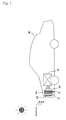
- Fig. 1 is an illustrative drawing for schematically describing 1 embodiment of a vehicle having on board an on-vehicle air-conditioner for air-conditioning of the present invention.
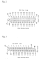
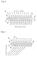
- Fig. 2 to 5 are illustrative drawings for schematically describing shape examples and use examples of an opening and closing duct for air inflow rate regulation used in the present invention.
- FIG. 1 40 represent a vehicle having on board an on-vehicle air-conditioner for air-conditioning of the present invention, 41 an engine and 42 a fan or others. And a refrigerant car exterior heat exchanger 12 provided in the on-vehicle air-conditioner for air-conditioning of the present invention is installed in front of the vehicle 40, and a cooling water car exterior heat exchanger 21 designated as so-called radiator where the cooling water circulates in order to cool the engine 41 is installed behind the same.
- a first opening and closing duct for air inflow rate regulation 43 is fitted in front of and adjacent to the refrigerant car exterior heat exchanger 12, and a second opening and closing duct for air inflow rate regulation 44 is fitted behind and adjacent to the refrigerant car exterior heat exchanger 12.
- the first opening and closing duct for air inflow rate regulation 43 and the second opening and closing duct for air inflow rate regulation 44 may be fitted; however, the first opening and closing duct for air inflow rate regulation 43 may be alone, the second opening and closing duct for air inflow rate regulation 44 may be alone, and they be conveniently selected and fitted.
- the opening and closing duct for air inflow rate regulation 43 (opening and closing duct for air inflow rate regulation 44 may also be of the same composition as 43) comprises a base material 45, a number of movable lovers 46 mounted on the base metal 45, a take-up machine 47 disposed at one end of the base metal 45, a wire for opening regulation 48 linked to the take-up machine 47, or others and the air inflow rate can be adjusted through the rotation of the movable lovers 46 by winding up the wire for opening regulation 48 or, on the contrary, by unwinding the wire for opening regulation 48, through the automatic or manual operation of the take-up machine.
- Material and shape of the base material 45 or movable lover 46, or the moving method of the movable lover 46 are not specified particularly.
- material of the base material 45 or movable lover 46 not only metals such as aluminum, but also, for example, engineering plastic materials presenting light weight, good strength, heat resistance, heat insulation or others can be used advantageously.
- Fig. 2 normally, it is preferable to compose to increase the air inflow rate by positioning the movable lover 46 of the opening and closing duct for air inflow rate regulation 43 and opening and closing duct for air inflow rate regulation 44 approximately at right angles to the base material 45.
- frosting may sometimes happen on the refrigerant car exterior heat exchanger 12, when the refrigeration circuit is used for heating during the travel of the vehicle 40 in winter or others.
- the air inflow rate is reduced by positioning the movable lover 46 of the first opening and closing duct for air inflow rate regulation 43 in the full-open state, as shown in Fig. 3, in order to prevent a quantity of cold air from entering the refrigerant car exterior heat exchanger 12 during the travel.
- the refrigerant car exterior heat exchanger 12 can be defrosted easily, as the cold air does not enter there, and there will be no problem of performance deterioration of the refrigerant car exterior heat exchanger 12.
- the second opening and closing duct for air inflow rate regulation 44 is not particularly specified, it is preferable to let the movable lover 46 for example in full-close, half-open or full-open state.
- the movable lover 46 of the first opening and closing duct for air inflow rate regulation 43 is controlled to close and, at the same time, the movable lover 46 of the second opening and closing duct for air inflow rate regulation 44 is positioned to in a full-open state, and the speed of rotations of is reduced by rotating the fan 42 in the reverse direction so as to send the air used for cooling the engine 41 and increased in temperature to pass through the refrigerant car exterior heat exchanger 12.
- the air used for cooling a driving motor or a motor driving circuit and increased in temperature is sent to pass through the refrigerant car exterior heat exchanger 12.
- the movable lover 46 of the first opening and closing duct for air inflow rate regulation 43 is controlled to close and the fan 42 is stopped.
- the movable lover 46 of the second opening and closing duct for air inflow rate regulation 44 it is not particularly specified, and is positioned for example in the full-close, half-open or full-open state.
- the refrigerant car exterior heat exchanger 12 can be defrosted easily, as the cold air does not enter there, and there will be no problem of performance deterioration of the refrigerant car exterior heat exchanger 12.
- the movable lover 46 of the first opening and closing duct for air inflow rate regulation 43 is positioned to the half-open state for setting the air inflow rate to the medium level.
- the deterioration of cooling capacity of the refrigerant car exterior heat exchanger 12 can be controlled, prevented by deterring the air heated to a high temperature by the heat from the road surface in asphalt or concrete or the exhaust heat from vehicle traveling ahead from flowing in the refrigerant car exterior heat exchanger 12.
- the deterioration of refrigeration efficiency of the refrigerant car exterior heat exchanger 12 can be controlled, prevented by blocking most of radiation heat from the engine 41 (or from a driver such as a not shown motor) by positioning also the movable lover 46 of the second opening and closing duct for air inflow rate regulation 44 to the half-open state.
- the vehicle 40 when the vehicle 40 is traveling using the refrigeration circuit for cooling during a summer high temperature time or the like, if the refrigerant car exterior heat exchanger 12 is exposed to an intense direct sunshine and heated and exerts adversely on the heat exchange, as shown in Fig. 5, the influence of sunshine can be reduced by positioning the movable lover 46 of the first opening and closing duct for air inflow rate regulation 43 approximately to the half-open state.
- the deterioration of refrigeration efficiency of the refrigerant car exterior heat exchanger 12 can be controlled, prevented by blocking most of radiation heat from the engine 41 by positioning also the movable lover 46 of the second opening and closing duct for air inflow rate regulation 44 to the half-open state, for example.
- the car interior sometimes cannot be cooled sufficiently, if the deterioration of refrigeration efficiency of the refrigerant car exterior heat exchanger 12 due to the heat from the road surface in asphalt or concrete or the exhaust heat from vehicle traveling ahead, radiation heat from an engine, or intense sunshine increases the refrigerant temperature and lowers the refrigerating capacity; however, the use of the on-vehicle air-conditioner for air-conditioning permits to assure a satisfactory cooling of the car interior even in case of using CO 2 as refrigerant.
- the on-vehicle air-conditioner for air-conditioning of claim 1 of the present invention is an on-vehicle air-conditioner for air-conditioning comprising a refrigeration circuit provided with a refrigerant car exterior heat exchanger installed for exchanging heat with the car exterior air that can be used for cooling and for heating, and at least one opening and closing duct for air inflow rate regulation installed in front of and/or behind the refrigerant car exterior heat exchanger, problems of the prior art can be resolved, cooling, having a remarkable effect of heating, defrosting or others can be performed effectively, even in case of using for example CO 2 refrigerant or hydrocarbon refrigerant, in vehicles such as hybrid cars taking electricity and gasoline as energy source, idle stop coping cars or others, by controlling conveniently the opening/closing of its opening and closing duct for air inflow rate regulation according to the situation.
- the on-vehicle air-conditioner for air-conditioning of claim 2 of the present invention is the on-vehicle air-conditioner for air-conditioning, wherein at least one of the ducts installed in front of and/or behind the refrigerant car exterior heat exchanger is controlled to close, for defrosting the frost deposited on the refrigerant car exterior heat exchanger by using the refrigeration circuit for heating during the travel in winter or others, having thereby a remarkable effect of deferring cold air from flowing in the refrigerant car exterior heat exchanger during the defrosting and allowing to defrost easily.
- the on-vehicle air-conditioner for air-conditioning of claim 3 of the present invention is the on-vehicle air-conditioner for air-conditioning, wherein at least one of the ducts installed in front of and/or behind the refrigerant car exterior heat exchanger is controlled to close, and the air used for cooling the engine, motor or motor driving circuit and increased in temperature is sent by lowering the speed of rotations through the reverse rotation of the fan so as to pass through the refrigerant car exterior heat exchanger, for defrosting the frost deposited on the refrigerant car exterior heat exchanger by using the refrigeration circuit for heating during the travel in winter or others, having thereby a remarkable effect of allowing to defrost more easily.
- the on-vehicle air-conditioner for air-conditioning of claim 4 of the present invention is the on-vehicle air-conditioner for air-conditioning, wherein at least one of the ducts installed in front of and/or behind the refrigerant car exterior heat exchanger is controlled to close, and the the fan is stopped, for defrosting the frost deposited on the refrigerant car exterior heat exchanger by using the refrigeration circuit for heating during the travel in winter or others, having thereby a remarkable effect of deferring cold air from flowing in the refrigerant car exterior heat exchanger during the defrosting and allowing to defrost easily.
- the on-vehicle air-conditioner for air-conditioning of claim 5 of the present invention is the on-vehicle air-conditioner for air-conditioning, wherein at least one of the ducts installed in front of and/or behind the refrigerant car exterior heat exchanger is controlled to half-open, during the use of the refrigeration circuit for cooling heating during a summer hot traffic congestion or others, having thereby a remarkable effect of preventing hot air from flowing so much in the refrigerant car exterior heat exchanger, blocking off the radiation heat of drivers such as engine, motor or others and allowing to cool the car interior sufficiently by controlling, preventing adverse effects by the engine radiation heat, exhaust heat of vehicles traveling ahead, or others.
- the on-vehicle air-conditioner for air-conditioning of claim 6 of the present invention is the on-vehicle air-conditioner for air-conditioning, wherein at least one of the ducts installed in front of and/or behind the refrigerant car exterior heat exchanger is controlled to half-open, in case where the direct sunshine affects adversely the heat exchange of the refrigerant car exterior heat exchanger, during the use of the refrigeration circuit for cooling, having thereby a remarkable effect of reducing the effect of direct sunshine, blocking off the radiation heat of drivers such as engine, motor or others and allowing to cool the car interior sufficiently.
- the on-vehicle air-conditioner for air-conditioning of claim 7 of the present invention is the on-vehicle air-conditioner for air-conditioning, wherein the refrigerant is CO 2 , having thereby remarkable effects of low load to the environment, absence of ozone layer destruction effect, combustibility or toxicity and, being extremely friendly to the environment as its global warming potential (GWP) is 1, and in addition, being economical. Further, it has a remarkable effect of controlling the elevation of the refrigerant temperature and assuring a satisfactory cooling of the car interior even when the refrigeration circuit is used for cooling during a summer hot time or others.
- GWP global warming potential
- the on-vehicle air-conditioner for air-conditioning of claim 8 of the present invention is the on-vehicle air-conditioner for air-conditioning, wherein the refrigerant is a hydrocarbon system refrigerant, having thereby remarkable effects of low load to the environment, absence of ozone layer destruction effect, combustibility or toxicity and, being extremely friendly to the environment as its global warming potemtial (GWP) is 1, and in addition, being economical. Further, it has a remarkable effect of controlling the elevation of the refrigerant temperature and assuring a satisfactory cooling of the car interior even when the refrigeration circuit is used for cooling during a summer hot time or others.
- GWP global warming potemtial
- the industrial use value of the on-vehicle air-conditioner for air-conditioning of the present invention comprising a refrigeration circuit provided with a refrigerant car exterior heat exchanger installed for exchanging heat with the car exterior air that can be used for cooling and for heating, and at least one opening and closing duct for air inflow rate regulation installed in front of and/or behind the refrigerant car exterior heat exchanger, is considerably important, because problems of the prior art can be resolved, cooling, heating, defrosting or others can be performed effectively, even in case of using for example CO 2 refrigerant or hydrocarbon refrigerant, in vehicles such as hybrid cars taking electricity and gasoline as energy source, idle stop coping cars or others, by controlling conveniently the opening/closing of its opening and closing duct for air inflow rate regulation according to the situation.
Landscapes
- Engineering & Computer Science (AREA)
- Mechanical Engineering (AREA)
- Physics & Mathematics (AREA)
- Thermal Sciences (AREA)
- Chemical & Material Sciences (AREA)
- Chemical Kinetics & Catalysis (AREA)
- General Engineering & Computer Science (AREA)
- Combustion & Propulsion (AREA)
- Transportation (AREA)
- Air-Conditioning For Vehicles (AREA)
Abstract
Description
Claims (8)
- An on-vehicle air-conditioner for air-conditioning comprising:a refrigeration circuit provided with a refrigerant car exterior heat exchanger installed for exchanging heat with the car exterior air that can be used for cooling and for heating, and at least one opening and closing duct for air inflow rate regulation installed in front of and/or behind said refrigerant car exterior heat exchanger.
- The on-vehicle air-conditioner for air-conditioning of claim 1, wherein at least one of said ducts installed in front of and/or behind said refrigerant car exterior heat exchanger is controlled to close, for defrosting the frost deposited on said refrigerant car exterior heat exchanger by using the refrigeration circuit for heating during the travel in winter or others.
- The on-vehicle air-conditioner for air-conditioning of claim 2, wherein at least one of said ducts installed in front of and/or behind said refrigerant car exterior heat exchanger is controlled to close, and the air used for cooling an engine, a motor or a motor driving circuit and increased in temperature is sent by lowering the speed of rotations through the reverse rotation of a fan so as to pass through said refrigerant car exterior heat exchanger, for defrosting the frost deposited on said refrigerant car exterior heat exchanger by using the refrigeration circuit for heating during the travel in winter or others.
- The on-vehicle air-conditioner for air-conditioning of claim 2, wherein at least one of said ducts installed in front of and/or behind said refrigerant car exterior heat exchanger is controlled to close, and the said fan is stopped, for defrosting the frost deposited on said refrigerant car exterior heat exchanger by using the refrigeration circuit for heating during the travel in winter or others.
- The on-vehicle air-conditioner for air-conditioning of claim 1,wherein at least one of said ducts installed in front of and/or behind said refrigerant car exterior heat exchanger is controlled to half-open, during the use of the refrigeration circuit for cooling during a summer hot traffic congestion or others.
- The on-vehicle air-conditioner for air-conditioning of claim 1 wherein at least one of said ducts installed in front of and/or behind said refrigerant car exterior heat exchanger is controlled to half-open, in case where the direct sunshine affects adversely the heat exchange of said refrigerant car exterior heat exchanger, during the use of the refrigeration circuit for cooling.
- The on-vehicle air-conditioner for air-conditioning of any of claims 1 to 6, wherein the refrigerant is CO2.
- The on-vehicle air-conditioner for air-conditioning of any of claims 1 to 6, wherein the refrigerant is a hydrocarbon system refrigerant.
Applications Claiming Priority (3)
| Application Number | Priority Date | Filing Date | Title |
|---|---|---|---|
| JP2001035994A JP3600164B2 (en) | 2001-02-13 | 2001-02-13 | Automotive air conditioners for cooling and heating |
| JP2001003599 | 2001-02-13 | ||
| PCT/JP2002/001154 WO2002064388A1 (en) | 2001-02-13 | 2002-02-12 | On-vehicle air conditioner for air conditioning |
Publications (3)
| Publication Number | Publication Date |
|---|---|
| EP1273467A1 true EP1273467A1 (en) | 2003-01-08 |
| EP1273467A4 EP1273467A4 (en) | 2004-09-29 |
| EP1273467B1 EP1273467B1 (en) | 2007-09-12 |
Family
ID=18899345
Family Applications (1)
| Application Number | Title | Priority Date | Filing Date |
|---|---|---|---|
| EP02711469A Expired - Lifetime EP1273467B1 (en) | 2001-02-13 | 2002-02-12 | On-vehicle air conditioner |
Country Status (6)
| Country | Link |
|---|---|
| US (1) | US7066245B2 (en) |
| EP (1) | EP1273467B1 (en) |
| JP (1) | JP3600164B2 (en) |
| CN (1) | CN100457487C (en) |
| DE (1) | DE60222332T2 (en) |
| WO (1) | WO2002064388A1 (en) |
Cited By (3)
| Publication number | Priority date | Publication date | Assignee | Title |
|---|---|---|---|---|
| EP2043885A4 (en) * | 2006-07-20 | 2010-06-16 | Carrier Corp | Improved heating for a transport refrigeration unit operating in cold ambients |
| DE102017115190A1 (en) | 2017-07-06 | 2019-01-10 | Denso Automotive Deutschland Gmbh | Arrangement and method for deicing a heat exchanger |
| EP4043252A1 (en) * | 2021-02-15 | 2022-08-17 | Volkswagen Ag | Method for initiating a defrosting process of a heat exchanger of a heat pump of a motor vehicle |
Families Citing this family (28)
| Publication number | Priority date | Publication date | Assignee | Title |
|---|---|---|---|---|
| JP4667141B2 (en) * | 2005-07-05 | 2011-04-06 | ヤンマー株式会社 | Swivel work vehicle |
| JP2008284963A (en) * | 2007-05-16 | 2008-11-27 | Honda Motor Co Ltd | vehicle |
| JP2010085042A (en) * | 2008-10-01 | 2010-04-15 | Mitsubishi Electric Corp | Refrigerating cycle device |
| US8550887B2 (en) * | 2009-09-18 | 2013-10-08 | Lacks Enterprises, Inc. | Vehicle grill with moveable louvers |
| DE102010034112A1 (en) * | 2010-08-12 | 2012-02-16 | Gm Global Technology Operations Llc (N.D.Ges.D. Staates Delaware) | Internal heat exchanger for a motor vehicle air conditioning system |
| JP2012237499A (en) * | 2011-05-11 | 2012-12-06 | Denso Corp | Heat storage defrosting device |
| JP5505385B2 (en) * | 2011-08-11 | 2014-05-28 | ダイキン工業株式会社 | Refrigeration equipment |
| CN102345911B (en) * | 2011-08-23 | 2013-10-09 | 中国北方车辆研究所 | Cooling and warming dual-purpose air-conditioning system for vehicles |
| US9487062B2 (en) * | 2012-10-19 | 2016-11-08 | Toyota Motor Engineering & Manufacturing North America, Inc. | Oil filled heater core |
| US9982929B2 (en) * | 2012-11-20 | 2018-05-29 | Samsung Electronics Co., Ltd. | Air conditioner |
| US9316141B2 (en) | 2013-02-15 | 2016-04-19 | Enis Pilavdzic | Engine energy management system |
| EP2829700B1 (en) | 2013-07-27 | 2024-01-10 | Meyer, Edo | Engine energy-management system |
| US10302346B2 (en) | 2014-07-16 | 2019-05-28 | Ford Global Technologies, Llc | Maximizing defrost mode in electrified vehicle having dual evaporator and dual heater core climate control system |
| US9819063B2 (en) * | 2015-08-18 | 2017-11-14 | Ford Global Technologies, Llc | Climate control system for a vehicle |
| KR20170069318A (en) * | 2015-12-10 | 2017-06-21 | 현대자동차주식회사 | Air conditioning system for vehicle |
| US10913332B2 (en) | 2016-03-31 | 2021-02-09 | Denso Corporation | Heat exchange unit |
| KR20190066029A (en) * | 2016-10-05 | 2019-06-12 | 바스프 에스이 | Active shutter vane for use in active vehicle grill systems |
| JP2018079757A (en) | 2016-11-15 | 2018-05-24 | 株式会社デンソー | Air stream circulation structure of vehicle |
| JP6673323B2 (en) * | 2017-03-08 | 2020-03-25 | 株式会社デンソー | Vehicle air conditioning controller |
| WO2018163765A1 (en) * | 2017-03-08 | 2018-09-13 | 株式会社デンソー | Air-conditioning control apparatus for vehicle |
| CN108151384A (en) * | 2018-01-10 | 2018-06-12 | 中国科学院广州能源研究所 | A kind of electric automobile heat-pump air-conditioning system vehicle external heat exchanger machinery defroster |
| JP2020093671A (en) * | 2018-12-13 | 2020-06-18 | 株式会社デンソー | Heat exchange unit |
| JP7375486B2 (en) * | 2018-12-14 | 2023-11-08 | 株式会社デンソー | Vehicle heat exchange system |
| CN110978950B (en) * | 2019-12-17 | 2021-09-21 | 东风商用车有限公司 | Automobile air conditioner and warm air linkage control system |
| JP7435308B2 (en) * | 2020-06-29 | 2024-02-21 | 株式会社デンソー | Refrigeration cycle equipment |
| JP2022174585A (en) * | 2021-05-11 | 2022-11-24 | トヨタ自動車株式会社 | Frost suppression device for vehicle |
| JP2022185274A (en) * | 2021-06-02 | 2022-12-14 | 三菱重工サーマルシステムズ株式会社 | Control system, mobile body, control method, and control program |
| CN114590103B (en) * | 2022-02-25 | 2024-03-19 | 智己汽车科技有限公司 | A solar powered vehicle air conditioner evaporator drying device and its control method |
Family Cites Families (34)
| Publication number | Priority date | Publication date | Assignee | Title |
|---|---|---|---|---|
| US1528575A (en) * | 1922-12-01 | 1925-03-03 | William H Schill | Automobile radiator shutter |
| US1660145A (en) * | 1926-06-01 | 1928-02-21 | Brewertitchener Corp | Control shutter for engine radiators |
| US1660146A (en) * | 1926-06-21 | 1928-02-21 | Brewertitchener Corp | Control shutter for engine radiators |
| JPS4943334A (en) * | 1972-09-01 | 1974-04-24 | ||
| US3823568A (en) * | 1973-08-29 | 1974-07-16 | T Bijasiewicz | Method and apparatus for air conditioning vehicles |
| US4383642A (en) * | 1980-03-22 | 1983-05-17 | Diesel Kiki Co., Ltd. | Heater unit for use in an air conditioner for automotive vehicles |
| US4539943A (en) * | 1983-09-20 | 1985-09-10 | Aisin Seiki Kabushiki Kaisha | Engine cooling system |
| JPS60248421A (en) * | 1984-05-21 | 1985-12-09 | Diesel Kiki Co Ltd | Air conditioner for car |
| JPS60259517A (en) * | 1984-06-04 | 1985-12-21 | Diesel Kiki Co Ltd | Air conditioner for automobile |
| JPS618574A (en) * | 1984-06-22 | 1986-01-16 | ヤンマーディーゼル株式会社 | Air conditioner for heat pump of engine |
| DE3438709C1 (en) * | 1984-10-23 | 1986-04-30 | Süddeutsche Kühlerfabrik Julius Fr. Behr GmbH & Co KG, 7000 Stuttgart | Radiator blind |
| JPS6322214A (en) | 1986-07-14 | 1988-01-29 | Yukio Kanazawa | Cutting machine for steel plate |
| JPS6322214U (en) * | 1986-07-30 | 1988-02-13 | ||
| JPS63312223A (en) * | 1987-06-15 | 1988-12-20 | Nissan Motor Co Ltd | Heater unit structure of air conditioner for vehicle |
| FR2627727B1 (en) * | 1988-02-26 | 1993-04-09 | Valeo | HEATING AND / OR AIR CONDITIONING DEVICE FOR A MOTOR VEHICLE |
| JPH0238131A (en) | 1988-07-29 | 1990-02-07 | Sanden Corp | Air conditioner for vehicle |
| JPH02185821A (en) * | 1989-01-12 | 1990-07-20 | Diesel Kiki Co Ltd | Air conditioner for automobile |
| JP2829024B2 (en) * | 1989-03-14 | 1998-11-25 | 株式会社日立製作所 | Automotive air conditioners |
| US5299431A (en) * | 1991-04-26 | 1994-04-05 | Nippondenso Co., Ltd. | Automotive air conditioner having condenser and evaporator provided within air duct |
| US5284025A (en) | 1991-06-17 | 1994-02-08 | Matsushita Electric Industrial Co., Ltd. | Air conditioning apparatus for an electrically-powered motor vehicle |
| JP3271287B2 (en) * | 1992-02-26 | 2002-04-02 | 松下電器産業株式会社 | Air conditioner for electric drive vehicle |
| JP3271288B2 (en) * | 1992-02-28 | 2002-04-02 | 松下電器産業株式会社 | Automotive air conditioners |
| JPH0664076U (en) * | 1993-02-15 | 1994-09-09 | 株式会社日本クライメイトシステムズ | Vehicle air conditioner |
| JP3160430B2 (en) * | 1993-08-09 | 2001-04-25 | 三菱重工業株式会社 | Heat pump type air conditioner for vehicles |
| KR960013745U (en) * | 1994-10-12 | 1996-05-17 | Car air conditioner | |
| DE4442000A1 (en) * | 1994-11-28 | 1996-05-30 | Behr Gmbh & Co | Heating and / or air conditioning |
| DE19629114B4 (en) | 1996-07-19 | 2007-10-18 | Behr Gmbh & Co. Kg | Device for heating and / or cooling a passenger compartment |
| DE19646123B4 (en) * | 1996-11-08 | 2008-03-27 | Behr Gmbh & Co. Kg | Heating or air conditioning for a motor vehicle |
| JPH11198637A (en) * | 1998-01-16 | 1999-07-27 | Mitsubishi Heavy Ind Ltd | Electric vehicle air conditioner |
| FR2774035B1 (en) * | 1998-01-29 | 2000-03-31 | Valeo Climatisation | MOTOR VEHICLE HEATING AND / OR AIR CONDITIONING DEVICE WITH IMPROVED HEAT EXCHANGE MANAGEMENT |
| DE19816329C2 (en) * | 1998-04-11 | 2001-06-07 | Daimler Chrysler Ag | Heating and air conditioning |
| DE19816322C2 (en) * | 1998-04-11 | 2003-03-06 | Wallisellen Ag Armaturen | Water meter connection and water meter unit |
| JPH11301254A (en) * | 1998-04-16 | 1999-11-02 | Tgk Co Ltd | Automotive air conditioners |
| DE19919975C1 (en) * | 1999-04-30 | 2000-09-07 | Daimler Chrysler Ag | Air conditioner unit for passenger side of vehicle has vaporizer, heat exchanger, air mixer chamber, air inlet and outlet, controls and air deflector flap |
-
2001
- 2001-02-13 JP JP2001035994A patent/JP3600164B2/en not_active Expired - Fee Related
-
2002
- 2002-02-12 WO PCT/JP2002/001154 patent/WO2002064388A1/en not_active Ceased
- 2002-02-12 EP EP02711469A patent/EP1273467B1/en not_active Expired - Lifetime
- 2002-02-12 US US10/258,084 patent/US7066245B2/en not_active Expired - Fee Related
- 2002-02-12 DE DE60222332T patent/DE60222332T2/en not_active Expired - Fee Related
- 2002-02-12 CN CNB028002814A patent/CN100457487C/en not_active Expired - Fee Related
Cited By (7)
| Publication number | Priority date | Publication date | Assignee | Title |
|---|---|---|---|---|
| EP2043885A4 (en) * | 2006-07-20 | 2010-06-16 | Carrier Corp | Improved heating for a transport refrigeration unit operating in cold ambients |
| CN101573244B (en) * | 2006-07-20 | 2013-01-02 | 开利公司 | Improved Heating for Transport Refrigeration Units Operating in Low Temperature Environments |
| DE102017115190A1 (en) | 2017-07-06 | 2019-01-10 | Denso Automotive Deutschland Gmbh | Arrangement and method for deicing a heat exchanger |
| US11040600B2 (en) | 2017-07-06 | 2021-06-22 | Denso Automotive Deutschland Gmbh | Arrangement and method for de-icing a heat exchanger |
| DE102017115190B4 (en) | 2017-07-06 | 2022-07-21 | Denso Automotive Deutschland Gmbh | Arrangement for defrosting a heat exchanger |
| EP4043252A1 (en) * | 2021-02-15 | 2022-08-17 | Volkswagen Ag | Method for initiating a defrosting process of a heat exchanger of a heat pump of a motor vehicle |
| US12285995B2 (en) | 2021-02-15 | 2025-04-29 | Volkswagen Aktiengesellschaft | Method for initiating a defrosting process of a heat exhanger of a heat pump of a motor vehicle and a corresponding motor vehicle |
Also Published As
| Publication number | Publication date |
|---|---|
| EP1273467A4 (en) | 2004-09-29 |
| US7066245B2 (en) | 2006-06-27 |
| DE60222332D1 (en) | 2007-10-25 |
| CN100457487C (en) | 2009-02-04 |
| WO2002064388A1 (en) | 2002-08-22 |
| US20040069481A1 (en) | 2004-04-15 |
| JP2002240548A (en) | 2002-08-28 |
| EP1273467B1 (en) | 2007-09-12 |
| DE60222332T2 (en) | 2007-12-27 |
| CN1457302A (en) | 2003-11-19 |
| JP3600164B2 (en) | 2004-12-08 |
Similar Documents
| Publication | Publication Date | Title |
|---|---|---|
| EP1273467B1 (en) | On-vehicle air conditioner | |
| JP5611072B2 (en) | Heat pump air conditioner for vehicle and defrosting method thereof | |
| JP3477868B2 (en) | Vehicle air conditioner | |
| EP2752315B1 (en) | Air-conditioning apparatus for vehicles | |
| JP4443588B2 (en) | Cold storage system for vehicles | |
| JP2002240540A (en) | In-vehicle air conditioner | |
| KR102047749B1 (en) | Heat pump system for vehicle | |
| US11260724B2 (en) | Vehicular air conditioning system and method for controlling the same | |
| JP2014156143A (en) | Vehicular air-conditioning device | |
| WO2021177057A1 (en) | Vehicle air conditioner | |
| CN115335245A (en) | Air conditioner for vehicle | |
| CN110475683B (en) | Air conditioning apparatus | |
| JP2012162149A (en) | Heat pump type vehicular air conditioner | |
| KR20120087444A (en) | Method for controlling air conditioning system of vehicle | |
| JPH06206439A (en) | Heat pump type air-conditioning device for vehicle | |
| Aurich et al. | Energy Efficient Heating and Air Conditioning Concept for City cars and Microcars | |
| JP2990995B2 (en) | Heat pump type air conditioner for vehicles | |
| WO2020241612A1 (en) | Vehicular air-conditioning device | |
| JP3334195B2 (en) | Heat pump type air conditioner for vehicles | |
| WO2020246305A1 (en) | Vehicle air conditioning device | |
| US20220185065A1 (en) | Method for operating a heat pump of an electric motor vehicle | |
| JPH1071848A (en) | Brine air conditioner | |
| JP3271288B2 (en) | Automotive air conditioners | |
| KR20230159178A (en) | Electric vehicle heat pump system | |
| KR20230164506A (en) | Electric vehicle heat pump system |
Legal Events
| Date | Code | Title | Description |
|---|---|---|---|
| PUAI | Public reference made under article 153(3) epc to a published international application that has entered the european phase |
Free format text: ORIGINAL CODE: 0009012 |
|
| 17P | Request for examination filed |
Effective date: 20020926 |
|
| AK | Designated contracting states |
Kind code of ref document: A1 Designated state(s): AT BE CH CY DE DK ES FI FR GB GR IE IT LI LU MC NL PT SE TR |
|
| A4 | Supplementary search report drawn up and despatched |
Effective date: 20040818 |
|
| 17Q | First examination report despatched |
Effective date: 20041109 |
|
| GRAP | Despatch of communication of intention to grant a patent |
Free format text: ORIGINAL CODE: EPIDOSNIGR1 |
|
| RTI1 | Title (correction) |
Free format text: ON-VEHICLE AIR CONDITIONER |
|
| RBV | Designated contracting states (corrected) |
Designated state(s): DE FR GB |
|
| GRAS | Grant fee paid |
Free format text: ORIGINAL CODE: EPIDOSNIGR3 |
|
| GRAA | (expected) grant |
Free format text: ORIGINAL CODE: 0009210 |
|
| AK | Designated contracting states |
Kind code of ref document: B1 Designated state(s): DE FR GB |
|
| REG | Reference to a national code |
Ref country code: GB Ref legal event code: FG4D |
|
| REF | Corresponds to: |
Ref document number: 60222332 Country of ref document: DE Date of ref document: 20071025 Kind code of ref document: P |
|
| ET | Fr: translation filed | ||
| PLBE | No opposition filed within time limit |
Free format text: ORIGINAL CODE: 0009261 |
|
| STAA | Information on the status of an ep patent application or granted ep patent |
Free format text: STATUS: NO OPPOSITION FILED WITHIN TIME LIMIT |
|
| 26N | No opposition filed |
Effective date: 20080613 |
|
| PGFP | Annual fee paid to national office [announced via postgrant information from national office to epo] |
Ref country code: DE Payment date: 20090206 Year of fee payment: 8 |
|
| PGFP | Annual fee paid to national office [announced via postgrant information from national office to epo] |
Ref country code: GB Payment date: 20090211 Year of fee payment: 8 |
|
| PGFP | Annual fee paid to national office [announced via postgrant information from national office to epo] |
Ref country code: FR Payment date: 20090213 Year of fee payment: 8 |
|
| GBPC | Gb: european patent ceased through non-payment of renewal fee |
Effective date: 20100212 |
|
| REG | Reference to a national code |
Ref country code: FR Ref legal event code: ST Effective date: 20101029 |
|
| PG25 | Lapsed in a contracting state [announced via postgrant information from national office to epo] |
Ref country code: FR Free format text: LAPSE BECAUSE OF NON-PAYMENT OF DUE FEES Effective date: 20100301 |
|
| PG25 | Lapsed in a contracting state [announced via postgrant information from national office to epo] |
Ref country code: DE Free format text: LAPSE BECAUSE OF NON-PAYMENT OF DUE FEES Effective date: 20100901 |
|
| PG25 | Lapsed in a contracting state [announced via postgrant information from national office to epo] |
Ref country code: GB Free format text: LAPSE BECAUSE OF NON-PAYMENT OF DUE FEES Effective date: 20100212 |