EP1273332A2 - Einfüllbecher für einen Flüssigkeitsfilter - Google Patents
Einfüllbecher für einen Flüssigkeitsfilter Download PDFInfo
- Publication number
- EP1273332A2 EP1273332A2 EP02012575A EP02012575A EP1273332A2 EP 1273332 A2 EP1273332 A2 EP 1273332A2 EP 02012575 A EP02012575 A EP 02012575A EP 02012575 A EP02012575 A EP 02012575A EP 1273332 A2 EP1273332 A2 EP 1273332A2
- Authority
- EP
- European Patent Office
- Prior art keywords
- filter
- tube
- base plate
- filling cup
- liquid
- Prior art date
- Legal status (The legal status is an assumption and is not a legal conclusion. Google has not performed a legal analysis and makes no representation as to the accuracy of the status listed.)
- Granted
Links
Images

Classifications
-
- B—PERFORMING OPERATIONS; TRANSPORTING
- B01—PHYSICAL OR CHEMICAL PROCESSES OR APPARATUS IN GENERAL
- B01D—SEPARATION
- B01D27/00—Cartridge filters of the throw-away type
- B01D27/08—Construction of the casing
-
- B—PERFORMING OPERATIONS; TRANSPORTING
- B01—PHYSICAL OR CHEMICAL PROCESSES OR APPARATUS IN GENERAL
- B01D—SEPARATION
- B01D35/00—Filtering devices having features not specifically covered by groups B01D24/00 - B01D33/00, or for applications not specifically covered by groups B01D24/00 - B01D33/00; Auxiliary devices for filtration; Filter housing constructions
- B01D35/30—Filter housing constructions
-
- F—MECHANICAL ENGINEERING; LIGHTING; HEATING; WEAPONS; BLASTING
- F02—COMBUSTION ENGINES; HOT-GAS OR COMBUSTION-PRODUCT ENGINE PLANTS
- F02M—SUPPLYING COMBUSTION ENGINES IN GENERAL WITH COMBUSTIBLE MIXTURES OR CONSTITUENTS THEREOF
- F02M37/00—Apparatus or systems for feeding liquid fuel from storage containers to carburettors or fuel-injection apparatus; Arrangements for purifying liquid fuel specially adapted for, or arranged on, internal-combustion engines
- F02M37/22—Arrangements for purifying liquid fuel specially adapted for, or arranged on, internal-combustion engines, e.g. arrangements in the feeding system
- F02M37/54—Arrangements for purifying liquid fuel specially adapted for, or arranged on, internal-combustion engines, e.g. arrangements in the feeding system characterised by air purging means
Definitions
- the invention relates to a filler cup for a Liquid filter, the liquid filter being a housing and a cover plate enclosing a filter element contains.
- the cover plate contains an inlet opening for Intake of unfiltered liquid, and a Outlet opening from which filtered liquid flows.
- Such filters are usually installed within a recommended service interval according to diesel engine Maintenance practices exchanged. If a device service provider a tin can-like (“screw-on") fuel filter a diesel engine, it is common for the new filter pre-fill with diesel fuel before installation. This reduces the break-in time that the system needed when the engine is started.
- the service provider pours fuel into the top of the filter, taking in This part contains openings with channels in the filtered or "clean" and with channels in the unfiltered or "dirty" side of the filter element are connected. It is difficult to do this prevent unfiltered fuel from entering the "clean" Side of the filter is poured. The result is that Contaminants can get into the fuel system, as soon as the engine is started. This can damage the Components of the fuel system and as a result whose reduce engine power.
- the object underlying the invention is seen in a filling cup for a liquid filter at the beginning Specify the type by which the aforementioned Problems are overcome.
- a Filling cup proposed for filling the fuel filter that prevents unfiltered fuel gets into the "clean" side of the filter.
- a disposable filling aid device is opened a tin can-like (“screw-on") fuel filter screwed.
- the fuel filter contains inlet openings, through which unfiltered fuel is passed and a central, preferably threaded Exhaust port from which filtered fuel flows.
- the Filling cup preferably contains a circular one Base plate and a cylindrical jacket.
- the filling cup contains a hollow tube, which is adapted to have an outlet opening of a Filters to be connected, the tube being a hollow Riser tube forms, which prevents fluid flows outside of the filter into the outlet opening of the filter.
- the air that is in the Filter is located when filling the filter to the environment directed.
- a Base plate included, which is firmly connected to the tube. Outside of the tube there are one on the base plate or a variety of openings. These openings conduct Fuel to intake ports and to an unfiltered or "dirty" side of the filter element of the filter after the filler cup was screwed onto the filter.
- the Base plate is surrounded by a circumferential jacket that is axial protrudes from the base plate and one with the base plate Cup forms that surrounds the tube.
- the hollow tube extends axially through the base plate and through the jacket, a part of the tube forming a stump which is formed from the Base plate protrudes downwards.
- the stump is like that molded that it fits the outlet opening of the filter can be connected and thus forms the connection between Filling cup and filter.
- the part of the tube that the stump is connected to the part of the pipe that forms the riser pipe shaped.
- the riser protrudes from the base plate an inside of the filler cup.
- the stump connects the filler cup with the filter.
- the stump and the riser together prevent that unfiltered fuel into the exhaust port or "clean" Side of the filter element of the filter flows.
- the stump and that Riser pipe also form an air duct to vent the Filters when it is filled with fuel.
- the base plate is designed such that it sealing with one on the cover plate of the filter seal is engaged when the filler cup mounted on the filter. This ensures that when filling the filter with the filler cup none Liquid is spilled and the liquid only the Possibility through the opening of the base plate in the Entrance opening of the filter.
- the upper side of the riser pipe with a push-on cap provided, the cap and the riser an air gap form between themselves.
- the cap prevents the Fill the filter with the filler cup of impurities into the riser pipe and into the "clean" side of the filter element reach.
- the air gap between the riser pipe and the push-on cap ensures that the air escapes through the air duct can if the fuel level is on the "clean" side of the Fuel filter rises.
- a depression on the edge of the jacket of the filler cup molded which represents a "thumb holder” so that the Filler cup assembled with the filter in can be held in one hand.
- Fuel filter 12 is screwed.
- the fuel filter includes a housing 14 and a cover plate 16 which a Include filter element 18, which in turn is a concentric, hollow filter tube 20 surrounds.
- the cover plate 16 includes a plurality of inlet openings 22 through which unfiltered fuel enters, and a centric Outlet opening 24 from which filtered fuel flows.
- On cover plate 16 is a conventional seal 26 assembled.
- the outlet opening 24 has an internal thread 27 provided, so that the filter 12 to a conventional Fuel system component (not shown) of a vehicle can be screwed.
- the filler cup 10 contains a rigid base plate 30 and a rigid cylindrical jacket 32 formed thereon, the protrudes axially from the base plate 30.
- a centric one hollow tube 31 extends axially through the base plate 30 and through the inside of the filler cup 10.
- One end of the Tube 31 forms a stump provided with an external thread 34, which is external to the filling cup 10 and which, starting from the base plate 30, from the inside of the Filler cup 10 extends.
- the stump 34 is preferably adapted such that he in the internal thread 27 of the outlet opening 24 in the Cover plate 16 of the filter 12 can be screwed.
- the Tube 31 also forms a hollow cylindrical riser tube 36, which is aligned with the stump 34 and which is of the base plate 30 into the interior of the filler cup 10 extends.
- a plurality of openings 38 are in the base plate 30 admitted. After the filling cup 10 is connected to the filter 12 is attached to the fuel through these openings 38 Inlets 22 and to the unfiltered or unclean side of the filter element 18 passed.
- the filling cup 10 is attached to the filter 12 with the stump 34 attached.
- the tube 31, the stump 34 and the Riser 36 forms, prevents unfiltered Liquid poured into the filler cup 10 into the Outlet openings 24 or clean side of the filter 12 flows.
- the tube 31 also forms a channel for out of the filter 12 escaping air when it is filled with liquid.
- On the upper end of the riser 36 is a push-on cap 40 to prevent contamination in the Inside of the riser 36 and in the clean side of the Arrive filter element 18.
- the cap 40 and the end of the Riser tube 36 form a gap or an air gap 42 to to allow air to escape when the fuel enters the filter 12.
- a depression or arcuate Cutout 44 on the edge of the jacket 32 represents one Thumb holder so that the one attached to the filter Filling cup 10 can be held with one hand.
- the filler cup 10 is attached to the filter 12, then stands the base plate 30 sealingly on the Cover plate 16 attached seal 26 in engagement so that Fuel can be poured into the filler cup 10.
- the fuel poured into the filler cup 10 flows through the Openings 38 and through the inlet openings 22 in the unfiltered side of the filter 12, through the filter element 18 through into the clean side of the filter 12 until the Fuel level has risen to the cover plate 16.
- the Filler cup 10 can then be removed and burned or to be discarded.
- the fuel-filled filter 12, can then be installed on the engine.
- the filling cup 10 can be made of different materials and with different Manufacturing processes are manufactured. It is suitable e.g. an injection molded composite. This filler cup 10 can in connection with diesel or with not for diesel provided engine fuel filter as well as for hydraulic and other types of liquid filters that have a basic filling need to be installed before installation.
- This invention proposes an affordable and practical one Means for priming a fuel exchange filter on one exhaust-gas-monitored diesel engine, preventing Fuel contaminants get into the fuel system.
Landscapes
- Chemical & Material Sciences (AREA)
- Engineering & Computer Science (AREA)
- Chemical Kinetics & Catalysis (AREA)
- Combustion & Propulsion (AREA)
- Mechanical Engineering (AREA)
- General Engineering & Computer Science (AREA)
- Filtration Of Liquid (AREA)
- Cooling, Air Intake And Gas Exhaust, And Fuel Tank Arrangements In Propulsion Units (AREA)
- Filtering Of Dispersed Particles In Gases (AREA)
- Filling Of Jars Or Cans And Processes For Cleaning And Sealing Jars (AREA)
- Filling, Topping-Up Batteries (AREA)
Abstract
Description
- Fig. 1
- einen perspektivischen Querschnitt eines erfindungsgemäßen Einfüllbechers, der an das obere Ende eines Aufschraub-Kraftstofffilters befestigt ist,
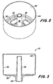
- Fig. 2
- eine perspektivische Ansicht des Einfüllbechers aus Fig. 1 und
- Fig. 3
- einen Querschnitt des Einfüllbechers aus Fig. 1
Claims (10)
- Einfüllbecher für ein Flüssigkeitsfilter (12), wobei das Flüssigkeitsfilter (12) ein Gehäuse (14) und eine ein Filterelement (18) einschließende Abdeckplatte (16) enthält, und die Abdeckplatte (16) wenigstens eine Einlassöffnung (22) zur Aufnahme von ungefilterter Flüssigkeit und eine Auslassöffnung (24) enthält, aus der gefilterte Flüssigkeit fließt, dadurch gekennzeichnet, dass der Einfüllbecher ein hohles Rohr (31) enthält, welches so angepasst ist, dass es mit der Auslassöffnung (24) des Filters (12) verbindbar ist, wobei das Rohr (31) ein hohles Steigrohr (36) bildet, welches verhindert, dass Flüssigkeit unter Umgehung des Filters (12) in die Auslassöffnung (24) des Filters (12) fließt.
- Einfüllbecher nach Anspruch 1, dadurch gekennzeichnet, dass das hohle Rohr (31) Luft aus dem Filter (12) an die Umgebung leitet, wenn das Filter (12) mit Flüssigkeit gefüllt wird.
- Einfüllbecher nach Anspruch 1 oder 2, gekennzeichnet durch eine fest mit dem Rohr (31) verbundene Grundplatte (30), die eine Öffnung (38) außerhalb des Rohres (31) aufweist und einen axial aus der Grundplatte (30) herausragenden, umlaufenden Mantel (32) enthält, wobei der Mantel (32) und die Grundplatte (30) einen Becher (10) formen, der das Rohr (31) umgibt.
- Einfüllbecher nach Anspruch 3, dadurch gekennzeichnet, dass das hohle Rohr (31) sich axial durch die Grundplatte (30) und den Mantel (32) erstreckt, wobei das Rohr einen Stumpf (34) formt, der aus der Grundplatte (30) herausragt und angepasst ist, um mit der Auslassöffnung (24) des Filters (12) verbunden zu werden.
- Einfüllbecher nach Anspruch 3 oder 4, dadurch gekennzeichnet, dass die Grundplatte (30) wenigstens eine Öffnung (38) enthält, durch die Flüssigkeit zu der Einlassöffnung (22) des Filters (12) geleitet wird.
- Einfüllbecher nach Anspruch 4 oder 5, dadurch gekennzeichnet, dass das Rohr (31) ein hohles Steigrohr (36) formt, welches mit dem Stumpf (34) verbunden ist und aus der Grundplatte (30) heraus- und in ein Inneres des Einfüllbechers hineinragt.
- Einfüllbecher nach einem der Ansprüche 4 bis 6, dadurch gekennzeichnet, dass der Stumpf (34) ein Außengewinde zum Einschrauben in die Auslassöffnung (24) des Filter (12) enthält.
- Einfüllbecher nach einem der Ansprüche 4 bis 7, dadurch gekennzeichnet, dass die Grundplatte (30) abdichtend mit einer auf die Abdeckplatte (16) des Filters (12) montierten Dichtung (26) in Eingriff steht.
- Einfüllbecher nach einem der Ansprüche 1 bis 8, dadurch gekennzeichnet, dass eine Aufsteckkappe (40) an ein Ende des Steigrohres (36) aufgesetzt ist und zwischen Kappe (40) und Steigrohr (36) ein Luftspalt ausgebildet ist.
- Einfüllbecher nach einem der Ansprüche 3 bis 9, dadurch gekennzeichnet, dass an einem Rand des Mantels (32) eine Vertiefung (44) ausgeformt ist.
Applications Claiming Priority (2)
| Application Number | Priority Date | Filing Date | Title |
|---|---|---|---|
| US880267 | 2001-06-13 | ||
| US09/880,267 US6571836B2 (en) | 2001-06-13 | 2001-06-13 | Filler cup for fluid filter |
Publications (3)
| Publication Number | Publication Date |
|---|---|
| EP1273332A2 true EP1273332A2 (de) | 2003-01-08 |
| EP1273332A3 EP1273332A3 (de) | 2003-03-12 |
| EP1273332B1 EP1273332B1 (de) | 2005-06-15 |
Family
ID=25375896
Family Applications (1)
| Application Number | Title | Priority Date | Filing Date |
|---|---|---|---|
| EP02012575A Expired - Lifetime EP1273332B1 (de) | 2001-06-13 | 2002-06-06 | Einfüllbecher für einen Flüssigkeitsfilter |
Country Status (5)
| Country | Link |
|---|---|
| US (1) | US6571836B2 (de) |
| EP (1) | EP1273332B1 (de) |
| CA (1) | CA2383199C (de) |
| DE (1) | DE50203401D1 (de) |
| MX (1) | MXPA02005571A (de) |
Cited By (1)
| Publication number | Priority date | Publication date | Assignee | Title |
|---|---|---|---|---|
| EP2762634B1 (de) * | 2013-02-01 | 2017-08-30 | Panasonic Corporation | Wäschetrockner |
Families Citing this family (8)
| Publication number | Priority date | Publication date | Assignee | Title |
|---|---|---|---|---|
| US20060186030A1 (en) * | 2005-02-22 | 2006-08-24 | Sohn Rachel A | Filter flushing system and adapter |
| US8365924B2 (en) * | 2008-08-07 | 2013-02-05 | Caterpillar Inc. | Systems and methods for filtering fuel |
| US7828154B2 (en) * | 2008-12-19 | 2010-11-09 | Caterpillar Inc | Systems and methods for filtering fuel |
| DE102013016684B4 (de) * | 2013-10-09 | 2019-01-17 | Kautex Textron Gmbh & Co. Kg | Einfüllstutzen für einen Kraftfahrzeug-Betriebsflüssigkeitsbehälter |
| US10252836B2 (en) * | 2015-10-08 | 2019-04-09 | Stephen Frank Charles Geldard | Applicator apparatus, mouth fill devices, collapsible containers and methods |
| CN107255579B (zh) * | 2017-06-12 | 2019-12-24 | 上海莫杜生物科技有限公司 | 一种一次性微生物样本接种杯及其接种方法和洗痰方法 |
| US11673080B2 (en) | 2019-06-04 | 2023-06-13 | Michael F. Dolan | Fluid filling diverter and collector apparatus |
| US20260085786A1 (en) * | 2024-09-24 | 2026-03-26 | Canadian Tire Corporation, Limited | Container for collecting and containing a liquid drained from a vehicle |
Family Cites Families (9)
| Publication number | Priority date | Publication date | Assignee | Title |
|---|---|---|---|---|
| US530228A (en) * | 1894-12-04 | Automatic funnel | ||
| US3973602A (en) * | 1970-01-13 | 1976-08-10 | Kruse Frederick W | Funnel with signal |
| US4112984A (en) | 1977-07-26 | 1978-09-12 | Gaston Guglia | Capped fuel tank funnel |
| EP0288899A3 (de) * | 1987-04-30 | 1988-11-30 | Valentino Ribi | Verfahren und Maschine zum Herstellen von Kaffee |
| US4824567A (en) | 1988-02-08 | 1989-04-25 | Filter Systems, Inc. | Fuel oil filter assembly |
| US5171430A (en) * | 1991-05-17 | 1992-12-15 | Fleetguard, Inc. | Plastic filter |
| US5275213A (en) | 1993-01-22 | 1994-01-04 | Perko, Inc. | Fuel filling and venting device |
| US5819822A (en) * | 1996-03-29 | 1998-10-13 | Caterpillar Inc. | Fluid filler tool for a spin-on fluid filter |
| US5899193A (en) | 1997-11-18 | 1999-05-04 | General Motors Corporation | Diesel engine fuel system and method of priming |
-
2001
- 2001-06-13 US US09/880,267 patent/US6571836B2/en not_active Expired - Fee Related
-
2002
- 2002-04-23 CA CA002383199A patent/CA2383199C/en not_active Expired - Fee Related
- 2002-06-05 MX MXPA02005571A patent/MXPA02005571A/es active IP Right Grant
- 2002-06-06 DE DE50203401T patent/DE50203401D1/de not_active Expired - Fee Related
- 2002-06-06 EP EP02012575A patent/EP1273332B1/de not_active Expired - Lifetime
Cited By (1)
| Publication number | Priority date | Publication date | Assignee | Title |
|---|---|---|---|---|
| EP2762634B1 (de) * | 2013-02-01 | 2017-08-30 | Panasonic Corporation | Wäschetrockner |
Also Published As
| Publication number | Publication date |
|---|---|
| US6571836B2 (en) | 2003-06-03 |
| EP1273332B1 (de) | 2005-06-15 |
| DE50203401D1 (de) | 2005-07-21 |
| CA2383199A1 (en) | 2002-12-13 |
| CA2383199C (en) | 2005-06-21 |
| US20020189710A1 (en) | 2002-12-19 |
| MXPA02005571A (es) | 2003-01-07 |
| EP1273332A3 (de) | 2003-03-12 |
Similar Documents
| Publication | Publication Date | Title |
|---|---|---|
| EP1980307B1 (de) | Flüssigkeitsfilter mit einer Entleerungsvorrichtung | |
| EP1342003B1 (de) | Vorrichtung zur kraftstoffversorgung einer brennkraftmaschine mit einem kraftstoffilter | |
| DE69021792T2 (de) | Kraftstoff-Filter. | |
| DE19716085B4 (de) | Filter, insbesondere für Kraftstoffe von Verbrennungsmotoren | |
| DE69935981T2 (de) | Flüssigkeitsfilter mit ersetzbarem filterelement | |
| EP1131542B1 (de) | Flüssigkeitsfilter, insbesondere für öl oder kraftstoff einer brennkraftmaschine | |
| EP1198682B1 (de) | Schnellkupplung für das öffnen eines ventils | |
| DE69414814T2 (de) | Hauptfiltrationsmodul für Brennstoff mit wahlweisen Umstellmöglichkeiten | |
| EP2054133A1 (de) | Flüssigkeitsfilter, insbesondere für kraftfahrzeuge | |
| WO1999013203A1 (de) | Ölpumpenmodul mit filter, insbesondere für das schmieröl einer brennkraftmaschine | |
| DE102005012550A1 (de) | Filter-Kühler-Kombination für Flüssigkeiten, insbesondere Schmieröl eines Kraftfahrzeug-Verbrennungsmotors | |
| EP1222010B1 (de) | Flüssigkeitsfilter, insbesondere ölfilter | |
| DE202014011016U1 (de) | Becherförmiges Gehäuse und Vorrichtung zum Abscheiden von Flüssigkeit aus Luft | |
| DE112015001643T5 (de) | Erdgasfilter mit Einrastfunktion | |
| EP1273332A2 (de) | Einfüllbecher für einen Flüssigkeitsfilter | |
| DE102014016561A1 (de) | Flüssigkeitsfilter, Funktionsmodul, Anschlussteil, Filterelement und Filtermodul eines Flüssigkeitsfilters | |
| DE69503854T2 (de) | Pumpeneinheit enthaltend einen Druckregler, für Fahrzeugkraftstoffbehälter und Behälter damit ausgerüstet | |
| DE102004061109A1 (de) | Flüssigkeitswechselfilter | |
| DE19713091A1 (de) | Brennstoffeinfüllwerkzeug für einen aufdrehbaren Strömungsmittelfilter | |
| DE102004061108B4 (de) | Flüssigkeitsfilter | |
| DE29922324U1 (de) | Flüssigkeitsfilter | |
| DE102014008235A1 (de) | Filterkopf für einen Wechsel- oder Gehäusefilter | |
| EP1090666A1 (de) | Flüssigkeitsfilter mit Schlauchstutzen als Anschluss | |
| DE3810987C2 (de) | Vorrichtung zum Behandeln des Kraftstoffes eines Dieselmotors | |
| DE3242004A1 (de) | Wasserablassvorrichtung |
Legal Events
| Date | Code | Title | Description |
|---|---|---|---|
| PUAI | Public reference made under article 153(3) epc to a published international application that has entered the european phase |
Free format text: ORIGINAL CODE: 0009012 |
|
| AK | Designated contracting states |
Kind code of ref document: A2 Designated state(s): AT BE CH CY DE DK ES FI FR GB GR IE IT LI LU MC NL PT SE TR |
|
| AX | Request for extension of the european patent |
Free format text: AL;LT;LV;MK;RO;SI |
|
| PUAL | Search report despatched |
Free format text: ORIGINAL CODE: 0009013 |
|
| RIC1 | Information provided on ipc code assigned before grant |
Ipc: 7F 02M 37/22 B Ipc: 7B 01D 35/30 B Ipc: 7B 01D 27/08 A |
|
| AK | Designated contracting states |
Kind code of ref document: A3 Designated state(s): AT BE CH CY DE DK ES FI FR GB GR IE IT LI LU MC NL PT SE TR |
|
| AX | Request for extension of the european patent |
Extension state: AL LT LV MK RO SI |
|
| 17P | Request for examination filed |
Effective date: 20030912 |
|
| AKX | Designation fees paid |
Designated state(s): DE FR GB IT SE |
|
| 17Q | First examination report despatched |
Effective date: 20031210 |
|
| GRAP | Despatch of communication of intention to grant a patent |
Free format text: ORIGINAL CODE: EPIDOSNIGR1 |
|
| GRAS | Grant fee paid |
Free format text: ORIGINAL CODE: EPIDOSNIGR3 |
|
| GRAA | (expected) grant |
Free format text: ORIGINAL CODE: 0009210 |
|
| AK | Designated contracting states |
Kind code of ref document: B1 Designated state(s): DE FR GB IT SE |
|
| PG25 | Lapsed in a contracting state [announced via postgrant information from national office to epo] |
Ref country code: IT Free format text: LAPSE BECAUSE OF NON-PAYMENT OF DUE FEES Effective date: 20050615 |
|
| REG | Reference to a national code |
Ref country code: GB Ref legal event code: FG4D Free format text: NOT ENGLISH |
|
| REF | Corresponds to: |
Ref document number: 50203401 Country of ref document: DE Date of ref document: 20050721 Kind code of ref document: P |
|
| GBT | Gb: translation of ep patent filed (gb section 77(6)(a)/1977) |
Effective date: 20050802 |
|
| REG | Reference to a national code |
Ref country code: SE Ref legal event code: TRGR |
|
| ET | Fr: translation filed | ||
| PLBE | No opposition filed within time limit |
Free format text: ORIGINAL CODE: 0009261 |
|
| STAA | Information on the status of an ep patent application or granted ep patent |
Free format text: STATUS: NO OPPOSITION FILED WITHIN TIME LIMIT |
|
| 26N | No opposition filed |
Effective date: 20060316 |
|
| PGFP | Annual fee paid to national office [announced via postgrant information from national office to epo] |
Ref country code: FR Payment date: 20090617 Year of fee payment: 8 |
|
| PGFP | Annual fee paid to national office [announced via postgrant information from national office to epo] |
Ref country code: DE Payment date: 20090520 Year of fee payment: 8 Ref country code: GB Payment date: 20090625 Year of fee payment: 8 Ref country code: SE Payment date: 20090629 Year of fee payment: 8 |
|
| PGFP | Annual fee paid to national office [announced via postgrant information from national office to epo] |
Ref country code: IT Payment date: 20090625 Year of fee payment: 8 |
|
| PGRI | Patent reinstated in contracting state [announced from national office to epo] |
Ref country code: IT Effective date: 20091201 |
|
| EUG | Se: european patent has lapsed | ||
| GBPC | Gb: european patent ceased through non-payment of renewal fee |
Effective date: 20100606 |
|
| REG | Reference to a national code |
Ref country code: FR Ref legal event code: ST Effective date: 20110228 |
|
| PG25 | Lapsed in a contracting state [announced via postgrant information from national office to epo] |
Ref country code: IT Free format text: LAPSE BECAUSE OF NON-PAYMENT OF DUE FEES Effective date: 20100606 |
|
| PG25 | Lapsed in a contracting state [announced via postgrant information from national office to epo] |
Ref country code: DE Free format text: LAPSE BECAUSE OF NON-PAYMENT OF DUE FEES Effective date: 20110101 |
|
| PG25 | Lapsed in a contracting state [announced via postgrant information from national office to epo] |
Ref country code: FR Free format text: LAPSE BECAUSE OF NON-PAYMENT OF DUE FEES Effective date: 20100630 |
|
| PG25 | Lapsed in a contracting state [announced via postgrant information from national office to epo] |
Ref country code: GB Free format text: LAPSE BECAUSE OF NON-PAYMENT OF DUE FEES Effective date: 20100606 |
|
| PG25 | Lapsed in a contracting state [announced via postgrant information from national office to epo] |
Ref country code: SE Free format text: LAPSE BECAUSE OF NON-PAYMENT OF DUE FEES Effective date: 20100607 |