EP1271499A2 - Optical information recording medium - Google Patents
Optical information recording medium Download PDFInfo
- Publication number
- EP1271499A2 EP1271499A2 EP02013808A EP02013808A EP1271499A2 EP 1271499 A2 EP1271499 A2 EP 1271499A2 EP 02013808 A EP02013808 A EP 02013808A EP 02013808 A EP02013808 A EP 02013808A EP 1271499 A2 EP1271499 A2 EP 1271499A2
- Authority
- EP
- European Patent Office
- Prior art keywords
- layer
- recording medium
- optical information
- information recording
- dye
- Prior art date
- Legal status (The legal status is an assumption and is not a legal conclusion. Google has not performed a legal analysis and makes no representation as to the accuracy of the status listed.)
- Withdrawn
Links
- 230000003287 optical effect Effects 0.000 title claims abstract description 165
- 239000010410 layer Substances 0.000 claims abstract description 308
- 239000000758 substrate Substances 0.000 claims abstract description 89
- 239000012790 adhesive layer Substances 0.000 claims abstract description 38
- 239000000975 dye Substances 0.000 claims description 109
- 239000000853 adhesive Substances 0.000 claims description 72
- 230000001070 adhesive effect Effects 0.000 claims description 72
- 229920005989 resin Polymers 0.000 claims description 64
- 239000011347 resin Substances 0.000 claims description 64
- 239000000126 substance Substances 0.000 claims description 54
- 239000004417 polycarbonate Substances 0.000 claims description 41
- 229920000515 polycarbonate Polymers 0.000 claims description 40
- -1 polyethylene terephthalate Polymers 0.000 claims description 29
- 229920002284 Cellulose triacetate Polymers 0.000 claims description 20
- NNLVGZFZQQXQNW-ADJNRHBOSA-N [(2r,3r,4s,5r,6s)-4,5-diacetyloxy-3-[(2s,3r,4s,5r,6r)-3,4,5-triacetyloxy-6-(acetyloxymethyl)oxan-2-yl]oxy-6-[(2r,3r,4s,5r,6s)-4,5,6-triacetyloxy-2-(acetyloxymethyl)oxan-3-yl]oxyoxan-2-yl]methyl acetate Chemical compound O([C@@H]1O[C@@H]([C@H]([C@H](OC(C)=O)[C@H]1OC(C)=O)O[C@H]1[C@@H]([C@@H](OC(C)=O)[C@H](OC(C)=O)[C@@H](COC(C)=O)O1)OC(C)=O)COC(=O)C)[C@@H]1[C@@H](COC(C)=O)O[C@@H](OC(C)=O)[C@H](OC(C)=O)[C@H]1OC(C)=O NNLVGZFZQQXQNW-ADJNRHBOSA-N 0.000 claims description 20
- 238000010521 absorption reaction Methods 0.000 claims description 18
- 229920000728 polyester Polymers 0.000 claims description 16
- 229910052782 aluminium Inorganic materials 0.000 claims description 14
- 150000001252 acrylic acid derivatives Chemical class 0.000 claims description 12
- 150000002734 metacrylic acid derivatives Chemical class 0.000 claims description 12
- 229910052709 silver Inorganic materials 0.000 claims description 12
- 229910052737 gold Inorganic materials 0.000 claims description 10
- 239000004800 polyvinyl chloride Substances 0.000 claims description 10
- 229920000915 polyvinyl chloride Polymers 0.000 claims description 10
- 239000004925 Acrylic resin Substances 0.000 claims description 9
- 229920000178 Acrylic resin Polymers 0.000 claims description 9
- BZHJMEDXRYGGRV-UHFFFAOYSA-N Vinyl chloride Chemical compound ClC=C BZHJMEDXRYGGRV-UHFFFAOYSA-N 0.000 claims description 9
- 229910052802 copper Inorganic materials 0.000 claims description 9
- 239000003822 epoxy resin Substances 0.000 claims description 9
- 229920000647 polyepoxide Polymers 0.000 claims description 9
- 229920000098 polyolefin Polymers 0.000 claims description 9
- 229910052732 germanium Inorganic materials 0.000 claims description 8
- 229920000139 polyethylene terephthalate Polymers 0.000 claims description 8
- 239000005020 polyethylene terephthalate Substances 0.000 claims description 8
- 229910052710 silicon Inorganic materials 0.000 claims description 8
- 229910001220 stainless steel Inorganic materials 0.000 claims description 8
- 239000010935 stainless steel Substances 0.000 claims description 8
- 229910052719 titanium Inorganic materials 0.000 claims description 8
- 229910052725 zinc Inorganic materials 0.000 claims description 8
- BUNYBPVXEKRSGY-ONEGZZNKSA-N (1e)-buta-1,3-dien-1-amine Chemical compound N\C=C\C=C BUNYBPVXEKRSGY-ONEGZZNKSA-N 0.000 claims description 7
- QRUDEWIWKLJBPS-UHFFFAOYSA-N benzotriazole Chemical compound C1=CC=C2N[N][N]C2=C1 QRUDEWIWKLJBPS-UHFFFAOYSA-N 0.000 claims description 7
- 239000013039 cover film Substances 0.000 claims description 7
- 229910052738 indium Inorganic materials 0.000 claims description 7
- 229910052748 manganese Inorganic materials 0.000 claims description 7
- 239000001007 phthalocyanine dye Substances 0.000 claims description 7
- 229910052721 tungsten Inorganic materials 0.000 claims description 7
- 229910052726 zirconium Inorganic materials 0.000 claims description 7
- XAGFODPZIPBFFR-UHFFFAOYSA-N aluminium Chemical compound [Al] XAGFODPZIPBFFR-UHFFFAOYSA-N 0.000 claims description 6
- 229910052797 bismuth Inorganic materials 0.000 claims description 6
- 229910052793 cadmium Inorganic materials 0.000 claims description 6
- 229910052804 chromium Inorganic materials 0.000 claims description 6
- 229910052733 gallium Inorganic materials 0.000 claims description 6
- 229910052735 hafnium Inorganic materials 0.000 claims description 6
- 229910052741 iridium Inorganic materials 0.000 claims description 6
- 229910052742 iron Inorganic materials 0.000 claims description 6
- 229910052750 molybdenum Inorganic materials 0.000 claims description 6
- 229910052759 nickel Inorganic materials 0.000 claims description 6
- 229910052758 niobium Inorganic materials 0.000 claims description 6
- 229910052763 palladium Inorganic materials 0.000 claims description 6
- IEQIEDJGQAUEQZ-UHFFFAOYSA-N phthalocyanine Chemical compound N1C(N=C2C3=CC=CC=C3C(N=C3C4=CC=CC=C4C(=N4)N3)=N2)=C(C=CC=C2)C2=C1N=C1C2=CC=CC=C2C4=N1 IEQIEDJGQAUEQZ-UHFFFAOYSA-N 0.000 claims description 6
- 229910052697 platinum Inorganic materials 0.000 claims description 6
- 229910052702 rhenium Inorganic materials 0.000 claims description 6
- 229910052703 rhodium Inorganic materials 0.000 claims description 6
- 229910052707 ruthenium Inorganic materials 0.000 claims description 6
- 229910052715 tantalum Inorganic materials 0.000 claims description 6
- 229910052720 vanadium Inorganic materials 0.000 claims description 6
- 125000000391 vinyl group Chemical group [H]C([*])=C([H])[H] 0.000 claims description 6
- 229910052727 yttrium Inorganic materials 0.000 claims description 6
- 239000000987 azo dye Substances 0.000 claims description 5
- 239000012964 benzotriazole Substances 0.000 claims description 5
- 150000004696 coordination complex Chemical class 0.000 claims description 5
- QYKIQEUNHZKYBP-UHFFFAOYSA-N Vinyl ether Chemical class C=COC=C QYKIQEUNHZKYBP-UHFFFAOYSA-N 0.000 claims description 4
- 150000003926 acrylamides Chemical class 0.000 claims description 4
- 239000011521 glass Substances 0.000 claims description 4
- FQPSGWSUVKBHSU-UHFFFAOYSA-N methacrylamide Chemical class CC(=C)C(N)=O FQPSGWSUVKBHSU-UHFFFAOYSA-N 0.000 claims description 4
- 229920001567 vinyl ester resin Polymers 0.000 claims description 4
- ANRHNWWPFJCPAZ-UHFFFAOYSA-M thionine Chemical compound [Cl-].C1=CC(N)=CC2=[S+]C3=CC(N)=CC=C3N=C21 ANRHNWWPFJCPAZ-UHFFFAOYSA-M 0.000 claims 1
- 238000000576 coating method Methods 0.000 description 54
- 239000011248 coating agent Substances 0.000 description 46
- 239000010408 film Substances 0.000 description 40
- 238000000034 method Methods 0.000 description 40
- 238000005259 measurement Methods 0.000 description 36
- 230000000052 comparative effect Effects 0.000 description 32
- 238000011156 evaluation Methods 0.000 description 32
- 239000011241 protective layer Substances 0.000 description 32
- 239000000523 sample Substances 0.000 description 23
- 230000005855 radiation Effects 0.000 description 22
- 239000011295 pitch Substances 0.000 description 20
- 239000002904 solvent Substances 0.000 description 19
- 238000004528 spin coating Methods 0.000 description 19
- 239000003795 chemical substances by application Substances 0.000 description 18
- 239000000463 material Substances 0.000 description 16
- 239000004820 Pressure-sensitive adhesive Substances 0.000 description 15
- ZWEHNKRNPOVVGH-UHFFFAOYSA-N 2-Butanone Chemical compound CCC(C)=O ZWEHNKRNPOVVGH-UHFFFAOYSA-N 0.000 description 12
- NIXOWILDQLNWCW-UHFFFAOYSA-N acrylic acid group Chemical group C(C=C)(=O)O NIXOWILDQLNWCW-UHFFFAOYSA-N 0.000 description 12
- 239000011230 binding agent Substances 0.000 description 12
- CERQOIWHTDAKMF-UHFFFAOYSA-N Methacrylic acid Chemical compound CC(=C)C(O)=O CERQOIWHTDAKMF-UHFFFAOYSA-N 0.000 description 11
- 230000008859 change Effects 0.000 description 11
- 230000006866 deterioration Effects 0.000 description 11
- SMZOUWXMTYCWNB-UHFFFAOYSA-N 2-(2-methoxy-5-methylphenyl)ethanamine Chemical compound COC1=CC=C(C)C=C1CCN SMZOUWXMTYCWNB-UHFFFAOYSA-N 0.000 description 10
- 238000002310 reflectometry Methods 0.000 description 10
- 230000015572 biosynthetic process Effects 0.000 description 9
- 239000012071 phase Substances 0.000 description 9
- 239000004419 Panlite Substances 0.000 description 8
- 239000004743 Polypropylene Substances 0.000 description 8
- 150000008365 aromatic ketones Chemical class 0.000 description 8
- 229920001577 copolymer Polymers 0.000 description 8
- QSHDDOUJBYECFT-UHFFFAOYSA-N mercury Chemical compound [Hg] QSHDDOUJBYECFT-UHFFFAOYSA-N 0.000 description 8
- 229910052753 mercury Inorganic materials 0.000 description 8
- 239000000123 paper Substances 0.000 description 8
- 239000010949 copper Substances 0.000 description 7
- 230000003746 surface roughness Effects 0.000 description 7
- YMWUJEATGCHHMB-UHFFFAOYSA-N Dichloromethane Chemical compound ClCCl YMWUJEATGCHHMB-UHFFFAOYSA-N 0.000 description 6
- LFQSCWFLJHTTHZ-UHFFFAOYSA-N Ethanol Chemical compound CCO LFQSCWFLJHTTHZ-UHFFFAOYSA-N 0.000 description 6
- XEKOWRVHYACXOJ-UHFFFAOYSA-N Ethyl acetate Chemical compound CCOC(C)=O XEKOWRVHYACXOJ-UHFFFAOYSA-N 0.000 description 6
- ZMXDDKWLCZADIW-UHFFFAOYSA-N N,N-Dimethylformamide Chemical compound CN(C)C=O ZMXDDKWLCZADIW-UHFFFAOYSA-N 0.000 description 6
- 239000004721 Polyphenylene oxide Substances 0.000 description 6
- 239000006096 absorbing agent Substances 0.000 description 6
- IISBACLAFKSPIT-UHFFFAOYSA-N bisphenol A Chemical compound C=1C=C(O)C=CC=1C(C)(C)C1=CC=C(O)C=C1 IISBACLAFKSPIT-UHFFFAOYSA-N 0.000 description 6
- PXKLMJQFEQBVLD-UHFFFAOYSA-N bisphenol F Chemical compound C1=CC(O)=CC=C1CC1=CC=C(O)C=C1 PXKLMJQFEQBVLD-UHFFFAOYSA-N 0.000 description 6
- 150000001875 compounds Chemical class 0.000 description 6
- 229920001971 elastomer Polymers 0.000 description 6
- LYCAIKOWRPUZTN-UHFFFAOYSA-N ethylene glycol Natural products OCCO LYCAIKOWRPUZTN-UHFFFAOYSA-N 0.000 description 6
- 238000001125 extrusion Methods 0.000 description 6
- 229930195733 hydrocarbon Natural products 0.000 description 6
- 239000003999 initiator Substances 0.000 description 6
- 229920000570 polyether Polymers 0.000 description 6
- 229920002635 polyurethane Polymers 0.000 description 6
- 239000004814 polyurethane Substances 0.000 description 6
- QGKMIGUHVLGJBR-UHFFFAOYSA-M (4z)-1-(3-methylbutyl)-4-[[1-(3-methylbutyl)quinolin-1-ium-4-yl]methylidene]quinoline;iodide Chemical compound [I-].C12=CC=CC=C2N(CCC(C)C)C=CC1=CC1=CC=[N+](CCC(C)C)C2=CC=CC=C12 QGKMIGUHVLGJBR-UHFFFAOYSA-M 0.000 description 5
- NBUKAOOFKZFCGD-UHFFFAOYSA-N 2,2,3,3-tetrafluoropropan-1-ol Chemical compound OCC(F)(F)C(F)F NBUKAOOFKZFCGD-UHFFFAOYSA-N 0.000 description 5
- 239000004698 Polyethylene Substances 0.000 description 5
- 235000010724 Wisteria floribunda Nutrition 0.000 description 5
- 238000010894 electron beam technology Methods 0.000 description 5
- 229910052751 metal Inorganic materials 0.000 description 5
- 239000002184 metal Substances 0.000 description 5
- 238000002156 mixing Methods 0.000 description 5
- 229920003229 poly(methyl methacrylate) Polymers 0.000 description 5
- 229920000573 polyethylene Polymers 0.000 description 5
- 239000004926 polymethyl methacrylate Substances 0.000 description 5
- 229920001155 polypropylene Polymers 0.000 description 5
- VYPSYNLAJGMNEJ-UHFFFAOYSA-N silicon dioxide Inorganic materials O=[Si]=O VYPSYNLAJGMNEJ-UHFFFAOYSA-N 0.000 description 5
- LEJBBGNFPAFPKQ-UHFFFAOYSA-N 2-(2-prop-2-enoyloxyethoxy)ethyl prop-2-enoate Chemical compound C=CC(=O)OCCOCCOC(=O)C=C LEJBBGNFPAFPKQ-UHFFFAOYSA-N 0.000 description 4
- XFCMNSHQOZQILR-UHFFFAOYSA-N 2-[2-(2-methylprop-2-enoyloxy)ethoxy]ethyl 2-methylprop-2-enoate Chemical compound CC(=C)C(=O)OCCOCCOC(=O)C(C)=C XFCMNSHQOZQILR-UHFFFAOYSA-N 0.000 description 4
- INQDDHNZXOAFFD-UHFFFAOYSA-N 2-[2-(2-prop-2-enoyloxyethoxy)ethoxy]ethyl prop-2-enoate Chemical compound C=CC(=O)OCCOCCOCCOC(=O)C=C INQDDHNZXOAFFD-UHFFFAOYSA-N 0.000 description 4
- HCLJOFJIQIJXHS-UHFFFAOYSA-N 2-[2-[2-(2-prop-2-enoyloxyethoxy)ethoxy]ethoxy]ethyl prop-2-enoate Chemical compound C=CC(=O)OCCOCCOCCOCCOC(=O)C=C HCLJOFJIQIJXHS-UHFFFAOYSA-N 0.000 description 4
- XLLIQLLCWZCATF-UHFFFAOYSA-N 2-methoxyethyl acetate Chemical compound COCCOC(C)=O XLLIQLLCWZCATF-UHFFFAOYSA-N 0.000 description 4
- KUDUQBURMYMBIJ-UHFFFAOYSA-N 2-prop-2-enoyloxyethyl prop-2-enoate Chemical compound C=CC(=O)OCCOC(=O)C=C KUDUQBURMYMBIJ-UHFFFAOYSA-N 0.000 description 4
- VVBLNCFGVYUYGU-UHFFFAOYSA-N 4,4'-Bis(dimethylamino)benzophenone Chemical compound C1=CC(N(C)C)=CC=C1C(=O)C1=CC=C(N(C)C)C=C1 VVBLNCFGVYUYGU-UHFFFAOYSA-N 0.000 description 4
- KWOLFJPFCHCOCG-UHFFFAOYSA-N Acetophenone Chemical compound CC(=O)C1=CC=CC=C1 KWOLFJPFCHCOCG-UHFFFAOYSA-N 0.000 description 4
- HEDRZPFGACZZDS-UHFFFAOYSA-N Chloroform Chemical compound ClC(Cl)Cl HEDRZPFGACZZDS-UHFFFAOYSA-N 0.000 description 4
- RTZKZFJDLAIYFH-UHFFFAOYSA-N Diethyl ether Chemical compound CCOCC RTZKZFJDLAIYFH-UHFFFAOYSA-N 0.000 description 4
- KFZMGEQAYNKOFK-UHFFFAOYSA-N Isopropanol Chemical compound CC(C)O KFZMGEQAYNKOFK-UHFFFAOYSA-N 0.000 description 4
- LRHPLDYGYMQRHN-UHFFFAOYSA-N N-Butanol Chemical compound CCCCO LRHPLDYGYMQRHN-UHFFFAOYSA-N 0.000 description 4
- WYURNTSHIVDZCO-UHFFFAOYSA-N Tetrahydrofuran Chemical compound C1CCOC1 WYURNTSHIVDZCO-UHFFFAOYSA-N 0.000 description 4
- 229910045601 alloy Inorganic materials 0.000 description 4
- 239000000956 alloy Substances 0.000 description 4
- RWCCWEUUXYIKHB-UHFFFAOYSA-N benzophenone Chemical compound C=1C=CC=CC=1C(=O)C1=CC=CC=C1 RWCCWEUUXYIKHB-UHFFFAOYSA-N 0.000 description 4
- 238000012937 correction Methods 0.000 description 4
- JHIVVAPYMSGYDF-UHFFFAOYSA-N cyclohexanone Chemical compound O=C1CCCCC1 JHIVVAPYMSGYDF-UHFFFAOYSA-N 0.000 description 4
- 230000003247 decreasing effect Effects 0.000 description 4
- SWXVUIWOUIDPGS-UHFFFAOYSA-N diacetone alcohol Chemical compound CC(=O)CC(C)(C)O SWXVUIWOUIDPGS-UHFFFAOYSA-N 0.000 description 4
- 150000002430 hydrocarbons Chemical class 0.000 description 4
- WGCNASOHLSPBMP-UHFFFAOYSA-N hydroxyacetaldehyde Natural products OCC=O WGCNASOHLSPBMP-UHFFFAOYSA-N 0.000 description 4
- ZFSLODLOARCGLH-UHFFFAOYSA-N isocyanuric acid Natural products OC1=NC(O)=NC(O)=N1 ZFSLODLOARCGLH-UHFFFAOYSA-N 0.000 description 4
- 150000002576 ketones Chemical class 0.000 description 4
- 239000000178 monomer Substances 0.000 description 4
- 239000002985 plastic film Substances 0.000 description 4
- 229920006255 plastic film Polymers 0.000 description 4
- 239000004431 polycarbonate resin Substances 0.000 description 4
- 229920005668 polycarbonate resin Polymers 0.000 description 4
- 229920005862 polyol Polymers 0.000 description 4
- 150000003077 polyols Chemical class 0.000 description 4
- BDERNNFJNOPAEC-UHFFFAOYSA-N propan-1-ol Chemical compound CCCO BDERNNFJNOPAEC-UHFFFAOYSA-N 0.000 description 4
- 239000004065 semiconductor Substances 0.000 description 4
- 239000000377 silicon dioxide Substances 0.000 description 4
- 230000007480 spreading Effects 0.000 description 4
- 238000003892 spreading Methods 0.000 description 4
- 229920000468 styrene butadiene styrene block copolymer Polymers 0.000 description 4
- 229920002554 vinyl polymer Polymers 0.000 description 4
- 239000004372 Polyvinyl alcohol Substances 0.000 description 3
- 230000001133 acceleration Effects 0.000 description 3
- 239000000654 additive Substances 0.000 description 3
- 239000003963 antioxidant agent Substances 0.000 description 3
- 230000003078 antioxidant effect Effects 0.000 description 3
- QVGXLLKOCUKJST-UHFFFAOYSA-N atomic oxygen Chemical compound [O] QVGXLLKOCUKJST-UHFFFAOYSA-N 0.000 description 3
- 229910052681 coesite Inorganic materials 0.000 description 3
- 229910052906 cristobalite Inorganic materials 0.000 description 3
- 238000001035 drying Methods 0.000 description 3
- 125000000524 functional group Chemical group 0.000 description 3
- 150000002894 organic compounds Chemical class 0.000 description 3
- 229910052760 oxygen Inorganic materials 0.000 description 3
- 239000001301 oxygen Substances 0.000 description 3
- 229920003023 plastic Polymers 0.000 description 3
- 239000004033 plastic Substances 0.000 description 3
- 229920002451 polyvinyl alcohol Polymers 0.000 description 3
- 238000012545 processing Methods 0.000 description 3
- 239000002356 single layer Substances 0.000 description 3
- 238000004544 sputter deposition Methods 0.000 description 3
- 229910052682 stishovite Inorganic materials 0.000 description 3
- 229910052905 tridymite Inorganic materials 0.000 description 3
- WSLDOOZREJYCGB-UHFFFAOYSA-N 1,2-Dichloroethane Chemical compound ClCCCl WSLDOOZREJYCGB-UHFFFAOYSA-N 0.000 description 2
- RYHBNJHYFVUHQT-UHFFFAOYSA-N 1,4-Dioxane Chemical compound C1COCCO1 RYHBNJHYFVUHQT-UHFFFAOYSA-N 0.000 description 2
- HSOOIVBINKDISP-UHFFFAOYSA-N 1-(2-methylprop-2-enoyloxy)butyl 2-methylprop-2-enoate Chemical compound CC(=C)C(=O)OC(CCC)OC(=O)C(C)=C HSOOIVBINKDISP-UHFFFAOYSA-N 0.000 description 2
- OGBWMWKMTUSNKE-UHFFFAOYSA-N 1-(2-methylprop-2-enoyloxy)hexyl 2-methylprop-2-enoate Chemical compound CCCCCC(OC(=O)C(C)=C)OC(=O)C(C)=C OGBWMWKMTUSNKE-UHFFFAOYSA-N 0.000 description 2
- ZDQNWDNMNKSMHI-UHFFFAOYSA-N 1-[2-(2-prop-2-enoyloxypropoxy)propoxy]propan-2-yl prop-2-enoate Chemical compound C=CC(=O)OC(C)COC(C)COCC(C)OC(=O)C=C ZDQNWDNMNKSMHI-UHFFFAOYSA-N 0.000 description 2
- 239000012956 1-hydroxycyclohexylphenyl-ketone Substances 0.000 description 2
- ARXJGSRGQADJSQ-UHFFFAOYSA-N 1-methoxypropan-2-ol Chemical compound COCC(C)O ARXJGSRGQADJSQ-UHFFFAOYSA-N 0.000 description 2
- VOBUAPTXJKMNCT-UHFFFAOYSA-N 1-prop-2-enoyloxyhexyl prop-2-enoate Chemical compound CCCCCC(OC(=O)C=C)OC(=O)C=C VOBUAPTXJKMNCT-UHFFFAOYSA-N 0.000 description 2
- PIZHFBODNLEQBL-UHFFFAOYSA-N 2,2-diethoxy-1-phenylethanone Chemical compound CCOC(OCC)C(=O)C1=CC=CC=C1 PIZHFBODNLEQBL-UHFFFAOYSA-N 0.000 description 2
- RXOZTUMCVTYUNS-UHFFFAOYSA-N 2,6-dimethylheptan-4-one;2-hydroxy-1,2-diphenylethanone Chemical compound CC(C)CC(=O)CC(C)C.C=1C=CC=CC=1C(O)C(=O)C1=CC=CC=C1 RXOZTUMCVTYUNS-UHFFFAOYSA-N 0.000 description 2
- JJBFVQSGPLGDNX-UHFFFAOYSA-N 2-(2-methylprop-2-enoyloxy)propyl 2-methylprop-2-enoate Chemical compound CC(=C)C(=O)OC(C)COC(=O)C(C)=C JJBFVQSGPLGDNX-UHFFFAOYSA-N 0.000 description 2
- XNWFRZJHXBZDAG-UHFFFAOYSA-N 2-METHOXYETHANOL Chemical compound COCCO XNWFRZJHXBZDAG-UHFFFAOYSA-N 0.000 description 2
- HWSSEYVMGDIFMH-UHFFFAOYSA-N 2-[2-[2-(2-methylprop-2-enoyloxy)ethoxy]ethoxy]ethyl 2-methylprop-2-enoate Chemical compound CC(=C)C(=O)OCCOCCOCCOC(=O)C(C)=C HWSSEYVMGDIFMH-UHFFFAOYSA-N 0.000 description 2
- OWDBMKZHFCSOOL-UHFFFAOYSA-N 2-[2-[2-(2-methylprop-2-enoyloxy)propoxy]propoxy]propyl 2-methylprop-2-enoate Chemical compound CC(=C)C(=O)OC(C)COC(C)COC(C)COC(=O)C(C)=C OWDBMKZHFCSOOL-UHFFFAOYSA-N 0.000 description 2
- LTHJXDSHSVNJKG-UHFFFAOYSA-N 2-[2-[2-[2-(2-methylprop-2-enoyloxy)ethoxy]ethoxy]ethoxy]ethyl 2-methylprop-2-enoate Chemical compound CC(=C)C(=O)OCCOCCOCCOCCOC(=O)C(C)=C LTHJXDSHSVNJKG-UHFFFAOYSA-N 0.000 description 2
- KTTCLOUATPWTNB-UHFFFAOYSA-N 2-[2-[4-(6,7-dimethoxy-3,4-dihydro-1h-isoquinolin-2-yl)butylcarbamoyl]-4-methylphenoxy]ethyl methanesulfonate Chemical compound C1C=2C=C(OC)C(OC)=CC=2CCN1CCCCNC(=O)C1=CC(C)=CC=C1OCCOS(C)(=O)=O KTTCLOUATPWTNB-UHFFFAOYSA-N 0.000 description 2
- KMNCBSZOIQAUFX-UHFFFAOYSA-N 2-ethoxy-1,2-diphenylethanone Chemical compound C=1C=CC=CC=1C(OCC)C(=O)C1=CC=CC=C1 KMNCBSZOIQAUFX-UHFFFAOYSA-N 0.000 description 2
- ZNQVEEAIQZEUHB-UHFFFAOYSA-N 2-ethoxyethanol Chemical compound CCOCCO ZNQVEEAIQZEUHB-UHFFFAOYSA-N 0.000 description 2
- KXGFMDJXCMQABM-UHFFFAOYSA-N 2-methoxy-6-methylphenol Chemical compound [CH]OC1=CC=CC([CH])=C1O KXGFMDJXCMQABM-UHFFFAOYSA-N 0.000 description 2
- VFZKVQVQOMDJEG-UHFFFAOYSA-N 2-prop-2-enoyloxypropyl prop-2-enoate Chemical compound C=CC(=O)OC(C)COC(=O)C=C VFZKVQVQOMDJEG-UHFFFAOYSA-N 0.000 description 2
- DBCAQXHNJOFNGC-UHFFFAOYSA-N 4-bromo-1,1,1-trifluorobutane Chemical compound FC(F)(F)CCCBr DBCAQXHNJOFNGC-UHFFFAOYSA-N 0.000 description 2
- JHWGFJBTMHEZME-UHFFFAOYSA-N 4-prop-2-enoyloxybutyl prop-2-enoate Chemical compound C=CC(=O)OCCCCOC(=O)C=C JHWGFJBTMHEZME-UHFFFAOYSA-N 0.000 description 2
- RSWGJHLUYNHPMX-UHFFFAOYSA-N Abietic-Saeure Natural products C12CCC(C(C)C)=CC2=CCC2C1(C)CCCC2(C)C(O)=O RSWGJHLUYNHPMX-UHFFFAOYSA-N 0.000 description 2
- 229920002972 Acrylic fiber Polymers 0.000 description 2
- DKPFZGUDAPQIHT-UHFFFAOYSA-N Butyl acetate Natural products CCCCOC(C)=O DKPFZGUDAPQIHT-UHFFFAOYSA-N 0.000 description 2
- 239000004215 Carbon black (E152) Substances 0.000 description 2
- RYGMFSIKBFXOCR-UHFFFAOYSA-N Copper Chemical compound [Cu] RYGMFSIKBFXOCR-UHFFFAOYSA-N 0.000 description 2
- 229920002307 Dextran Polymers 0.000 description 2
- 108010010803 Gelatin Proteins 0.000 description 2
- 244000043261 Hevea brasiliensis Species 0.000 description 2
- NTIZESTWPVYFNL-UHFFFAOYSA-N Methyl isobutyl ketone Chemical compound CC(C)CC(C)=O NTIZESTWPVYFNL-UHFFFAOYSA-N 0.000 description 2
- UIHCLUNTQKBZGK-UHFFFAOYSA-N Methyl isobutyl ketone Natural products CCC(C)C(C)=O UIHCLUNTQKBZGK-UHFFFAOYSA-N 0.000 description 2
- 239000004677 Nylon Substances 0.000 description 2
- 229920002319 Poly(methyl acrylate) Polymers 0.000 description 2
- 239000002202 Polyethylene glycol Substances 0.000 description 2
- 229920002367 Polyisobutene Polymers 0.000 description 2
- 239000004793 Polystyrene Substances 0.000 description 2
- 229920001328 Polyvinylidene chloride Polymers 0.000 description 2
- 229920000297 Rayon Polymers 0.000 description 2
- KHPCPRHQVVSZAH-HUOMCSJISA-N Rosin Natural products O(C/C=C/c1ccccc1)[C@H]1[C@H](O)[C@@H](O)[C@@H](O)[C@@H](CO)O1 KHPCPRHQVVSZAH-HUOMCSJISA-N 0.000 description 2
- ULQMPOIOSDXIGC-UHFFFAOYSA-N [2,2-dimethyl-3-(2-methylprop-2-enoyloxy)propyl] 2-methylprop-2-enoate Chemical compound CC(=C)C(=O)OCC(C)(C)COC(=O)C(C)=C ULQMPOIOSDXIGC-UHFFFAOYSA-N 0.000 description 2
- 238000002835 absorbance Methods 0.000 description 2
- VEBCLRKUSAGCDF-UHFFFAOYSA-N ac1mi23b Chemical compound C1C2C3C(COC(=O)C=C)CCC3C1C(COC(=O)C=C)C2 VEBCLRKUSAGCDF-UHFFFAOYSA-N 0.000 description 2
- 239000002253 acid Substances 0.000 description 2
- 150000001298 alcohols Chemical class 0.000 description 2
- 125000000217 alkyl group Chemical group 0.000 description 2
- 125000002947 alkylene group Chemical group 0.000 description 2
- 150000001408 amides Chemical class 0.000 description 2
- 229910052787 antimony Inorganic materials 0.000 description 2
- 239000012965 benzophenone Substances 0.000 description 2
- MQDJYUACMFCOFT-UHFFFAOYSA-N bis[2-(1-hydroxycyclohexyl)phenyl]methanone Chemical compound C=1C=CC=C(C(=O)C=2C(=CC=CC=2)C2(O)CCCCC2)C=1C1(O)CCCCC1 MQDJYUACMFCOFT-UHFFFAOYSA-N 0.000 description 2
- FACXGONDLDSNOE-UHFFFAOYSA-N buta-1,3-diene;styrene Chemical compound C=CC=C.C=CC1=CC=CC=C1.C=CC1=CC=CC=C1 FACXGONDLDSNOE-UHFFFAOYSA-N 0.000 description 2
- 239000001913 cellulose Substances 0.000 description 2
- 229920002678 cellulose Polymers 0.000 description 2
- 239000004927 clay Substances 0.000 description 2
- 238000007598 dipping method Methods 0.000 description 2
- 230000000694 effects Effects 0.000 description 2
- 150000002148 esters Chemical class 0.000 description 2
- 150000002170 ethers Chemical class 0.000 description 2
- LZCLXQDLBQLTDK-UHFFFAOYSA-N ethyl 2-hydroxypropanoate Chemical compound CCOC(=O)C(C)O LZCLXQDLBQLTDK-UHFFFAOYSA-N 0.000 description 2
- STVZJERGLQHEKB-UHFFFAOYSA-N ethylene glycol dimethacrylate Substances CC(=C)C(=O)OCCOC(=O)C(C)=C STVZJERGLQHEKB-UHFFFAOYSA-N 0.000 description 2
- 239000004744 fabric Substances 0.000 description 2
- 239000000945 filler Substances 0.000 description 2
- 125000001153 fluoro group Chemical group F* 0.000 description 2
- 239000011888 foil Substances 0.000 description 2
- 229920000159 gelatin Polymers 0.000 description 2
- 239000008273 gelatin Substances 0.000 description 2
- 235000019322 gelatine Nutrition 0.000 description 2
- 235000011852 gelatine desserts Nutrition 0.000 description 2
- 150000002334 glycols Chemical class 0.000 description 2
- FUZZWVXGSFPDMH-UHFFFAOYSA-M hexanoate Chemical compound CCCCCC([O-])=O FUZZWVXGSFPDMH-UHFFFAOYSA-M 0.000 description 2
- 238000011835 investigation Methods 0.000 description 2
- 238000007733 ion plating Methods 0.000 description 2
- 239000002655 kraft paper Substances 0.000 description 2
- 238000010030 laminating Methods 0.000 description 2
- 239000000314 lubricant Substances 0.000 description 2
- YDKNBNOOCSNPNS-UHFFFAOYSA-N methyl 1,3-benzoxazole-2-carboxylate Chemical compound C1=CC=C2OC(C(=O)OC)=NC2=C1 YDKNBNOOCSNPNS-UHFFFAOYSA-N 0.000 description 2
- UAEPNZWRGJTJPN-UHFFFAOYSA-N methylcyclohexane Chemical compound CC1CCCCC1 UAEPNZWRGJTJPN-UHFFFAOYSA-N 0.000 description 2
- 229920003052 natural elastomer Polymers 0.000 description 2
- 229920001194 natural rubber Polymers 0.000 description 2
- 229920001778 nylon Polymers 0.000 description 2
- OTLDLKLSNZMTTA-UHFFFAOYSA-N octahydro-1h-4,7-methanoindene-1,5-diyldimethanol Chemical compound C1C2C3C(CO)CCC3C1C(CO)C2 OTLDLKLSNZMTTA-UHFFFAOYSA-N 0.000 description 2
- 229920000620 organic polymer Polymers 0.000 description 2
- 230000035515 penetration Effects 0.000 description 2
- 229920001568 phenolic resin Polymers 0.000 description 2
- 239000004014 plasticizer Substances 0.000 description 2
- 229920002037 poly(vinyl butyral) polymer Polymers 0.000 description 2
- 229920005906 polyester polyol Polymers 0.000 description 2
- 229920001223 polyethylene glycol Polymers 0.000 description 2
- 229920001228 polyisocyanate Polymers 0.000 description 2
- 239000005056 polyisocyanate Substances 0.000 description 2
- 229920001451 polypropylene glycol Polymers 0.000 description 2
- 229920001296 polysiloxane Polymers 0.000 description 2
- 229920002223 polystyrene Polymers 0.000 description 2
- 239000005033 polyvinylidene chloride Substances 0.000 description 2
- 239000002964 rayon Substances 0.000 description 2
- 238000005096 rolling process Methods 0.000 description 2
- 238000007650 screen-printing Methods 0.000 description 2
- 230000003595 spectral effect Effects 0.000 description 2
- 238000001228 spectrum Methods 0.000 description 2
- 238000005507 spraying Methods 0.000 description 2
- 229920002994 synthetic fiber Polymers 0.000 description 2
- 239000012209 synthetic fiber Substances 0.000 description 2
- 229920005613 synthetic organic polymer Polymers 0.000 description 2
- YLQBMQCUIZJEEH-UHFFFAOYSA-N tetrahydrofuran Natural products C=1C=COC=1 YLQBMQCUIZJEEH-UHFFFAOYSA-N 0.000 description 2
- 229910052718 tin Inorganic materials 0.000 description 2
- KHPCPRHQVVSZAH-UHFFFAOYSA-N trans-cinnamyl beta-D-glucopyranoside Natural products OC1C(O)C(O)C(CO)OC1OCC=CC1=CC=CC=C1 KHPCPRHQVVSZAH-UHFFFAOYSA-N 0.000 description 2
- 238000002834 transmittance Methods 0.000 description 2
- XLYOFNOQVPJJNP-UHFFFAOYSA-N water Substances O XLYOFNOQVPJJNP-UHFFFAOYSA-N 0.000 description 2
- 239000002759 woven fabric Substances 0.000 description 2
- WBYWAXJHAXSJNI-VOTSOKGWSA-M .beta-Phenylacrylic acid Natural products [O-]C(=O)\C=C\C1=CC=CC=C1 WBYWAXJHAXSJNI-VOTSOKGWSA-M 0.000 description 1
- JYEUMXHLPRZUAT-UHFFFAOYSA-N 1,2,3-triazine Chemical compound C1=CN=NN=C1 JYEUMXHLPRZUAT-UHFFFAOYSA-N 0.000 description 1
- BCMCBBGGLRIHSE-UHFFFAOYSA-N 1,3-benzoxazole Chemical compound C1=CC=C2OC=NC2=C1 BCMCBBGGLRIHSE-UHFFFAOYSA-N 0.000 description 1
- MUZDXNQOSGWMJJ-UHFFFAOYSA-N 2-methylprop-2-enoic acid;prop-2-enoic acid Chemical compound OC(=O)C=C.CC(=C)C(O)=O MUZDXNQOSGWMJJ-UHFFFAOYSA-N 0.000 description 1
- 125000003903 2-propenyl group Chemical group [H]C([*])([H])C([H])=C([H])[H] 0.000 description 1
- NIXOWILDQLNWCW-UHFFFAOYSA-M Acrylate Chemical compound [O-]C(=O)C=C NIXOWILDQLNWCW-UHFFFAOYSA-M 0.000 description 1
- 229910000763 AgInSbTe Inorganic materials 0.000 description 1
- WBYWAXJHAXSJNI-SREVYHEPSA-N Cinnamic acid Chemical compound OC(=O)\C=C/C1=CC=CC=C1 WBYWAXJHAXSJNI-SREVYHEPSA-N 0.000 description 1
- XDTMQSROBMDMFD-UHFFFAOYSA-N Cyclohexane Chemical compound C1CCCCC1 XDTMQSROBMDMFD-UHFFFAOYSA-N 0.000 description 1
- 229910000618 GeSbTe Inorganic materials 0.000 description 1
- CNCOEDDPFOAUMB-UHFFFAOYSA-N N-Methylolacrylamide Chemical compound OCNC(=O)C=C CNCOEDDPFOAUMB-UHFFFAOYSA-N 0.000 description 1
- 239000000020 Nitrocellulose Substances 0.000 description 1
- 239000004642 Polyimide Substances 0.000 description 1
- 239000006087 Silane Coupling Agent Substances 0.000 description 1
- UCKMPCXJQFINFW-UHFFFAOYSA-N Sulphide Chemical compound [S-2] UCKMPCXJQFINFW-UHFFFAOYSA-N 0.000 description 1
- 206010044565 Tremor Diseases 0.000 description 1
- 238000005299 abrasion Methods 0.000 description 1
- 238000009825 accumulation Methods 0.000 description 1
- 125000005396 acrylic acid ester group Chemical group 0.000 description 1
- 230000004075 alteration Effects 0.000 description 1
- 239000002216 antistatic agent Substances 0.000 description 1
- 230000008901 benefit Effects 0.000 description 1
- 230000001588 bifunctional effect Effects 0.000 description 1
- 150000004770 chalcogenides Chemical class 0.000 description 1
- 238000006243 chemical reaction Methods 0.000 description 1
- 229930016911 cinnamic acid Natural products 0.000 description 1
- 235000013985 cinnamic acid Nutrition 0.000 description 1
- 239000007859 condensation product Substances 0.000 description 1
- 238000013500 data storage Methods 0.000 description 1
- 230000002950 deficient Effects 0.000 description 1
- 238000011161 development Methods 0.000 description 1
- 230000018109 developmental process Effects 0.000 description 1
- 150000002009 diols Chemical class 0.000 description 1
- 238000003618 dip coating Methods 0.000 description 1
- 229940116333 ethyl lactate Drugs 0.000 description 1
- 239000005038 ethylene vinyl acetate Substances 0.000 description 1
- 238000007765 extrusion coating Methods 0.000 description 1
- 230000006870 function Effects 0.000 description 1
- 229920002681 hypalon Polymers 0.000 description 1
- 230000001678 irradiating effect Effects 0.000 description 1
- 230000008018 melting Effects 0.000 description 1
- 238000002844 melting Methods 0.000 description 1
- DZVCFNFOPIZQKX-LTHRDKTGSA-M merocyanine Chemical compound [Na+].O=C1N(CCCC)C(=O)N(CCCC)C(=O)C1=C\C=C\C=C/1N(CCCS([O-])(=O)=O)C2=CC=CC=C2O\1 DZVCFNFOPIZQKX-LTHRDKTGSA-M 0.000 description 1
- 150000002736 metal compounds Chemical class 0.000 description 1
- 150000002739 metals Chemical class 0.000 description 1
- 229920003145 methacrylic acid copolymer Polymers 0.000 description 1
- 229940117841 methacrylic acid copolymer Drugs 0.000 description 1
- WBYWAXJHAXSJNI-UHFFFAOYSA-N methyl p-hydroxycinnamate Natural products OC(=O)C=CC1=CC=CC=C1 WBYWAXJHAXSJNI-UHFFFAOYSA-N 0.000 description 1
- GYNNXHKOJHMOHS-UHFFFAOYSA-N methyl-cycloheptane Natural products CC1CCCCCC1 GYNNXHKOJHMOHS-UHFFFAOYSA-N 0.000 description 1
- 239000003607 modifier Substances 0.000 description 1
- 150000004767 nitrides Chemical class 0.000 description 1
- 229920001220 nitrocellulos Polymers 0.000 description 1
- 230000010355 oscillation Effects 0.000 description 1
- 230000000704 physical effect Effects 0.000 description 1
- 229920001200 poly(ethylene-vinyl acetate) Polymers 0.000 description 1
- 229920006289 polycarbonate film Polymers 0.000 description 1
- 229920001721 polyimide Polymers 0.000 description 1
- 229920000642 polymer Polymers 0.000 description 1
- 238000006116 polymerization reaction Methods 0.000 description 1
- 239000011118 polyvinyl acetate Substances 0.000 description 1
- 229920002689 polyvinyl acetate Polymers 0.000 description 1
- 239000000843 powder Substances 0.000 description 1
- 230000001681 protective effect Effects 0.000 description 1
- 230000008929 regeneration Effects 0.000 description 1
- 238000011069 regeneration method Methods 0.000 description 1
- 238000011160 research Methods 0.000 description 1
- 150000003852 triazoles Chemical class 0.000 description 1
- 238000001132 ultrasonic dispersion Methods 0.000 description 1
- 238000007738 vacuum evaporation Methods 0.000 description 1
- 238000001947 vapour-phase growth Methods 0.000 description 1
Images

Classifications
-
- G—PHYSICS
- G11—INFORMATION STORAGE
- G11B—INFORMATION STORAGE BASED ON RELATIVE MOVEMENT BETWEEN RECORD CARRIER AND TRANSDUCER
- G11B7/00—Recording or reproducing by optical means, e.g. recording using a thermal beam of optical radiation by modifying optical properties or the physical structure, reproducing using an optical beam at lower power by sensing optical properties; Record carriers therefor
- G11B7/24—Record carriers characterised by shape, structure or physical properties, or by the selection of the material
- G11B7/26—Apparatus or processes specially adapted for the manufacture of record carriers
-
- G—PHYSICS
- G11—INFORMATION STORAGE
- G11B—INFORMATION STORAGE BASED ON RELATIVE MOVEMENT BETWEEN RECORD CARRIER AND TRANSDUCER
- G11B7/00—Recording or reproducing by optical means, e.g. recording using a thermal beam of optical radiation by modifying optical properties or the physical structure, reproducing using an optical beam at lower power by sensing optical properties; Record carriers therefor
- G11B7/24—Record carriers characterised by shape, structure or physical properties, or by the selection of the material
-
- G—PHYSICS
- G11—INFORMATION STORAGE
- G11B—INFORMATION STORAGE BASED ON RELATIVE MOVEMENT BETWEEN RECORD CARRIER AND TRANSDUCER
- G11B7/00—Recording or reproducing by optical means, e.g. recording using a thermal beam of optical radiation by modifying optical properties or the physical structure, reproducing using an optical beam at lower power by sensing optical properties; Record carriers therefor
- G11B7/24—Record carriers characterised by shape, structure or physical properties, or by the selection of the material
- G11B7/2407—Tracks or pits; Shape, structure or physical properties thereof
- G11B7/24073—Tracks
- G11B7/24079—Width or depth
-
- G—PHYSICS
- G11—INFORMATION STORAGE
- G11B—INFORMATION STORAGE BASED ON RELATIVE MOVEMENT BETWEEN RECORD CARRIER AND TRANSDUCER
- G11B7/00—Recording or reproducing by optical means, e.g. recording using a thermal beam of optical radiation by modifying optical properties or the physical structure, reproducing using an optical beam at lower power by sensing optical properties; Record carriers therefor
- G11B7/24—Record carriers characterised by shape, structure or physical properties, or by the selection of the material
- G11B7/241—Record carriers characterised by shape, structure or physical properties, or by the selection of the material characterised by the selection of the material
- G11B7/242—Record carriers characterised by shape, structure or physical properties, or by the selection of the material characterised by the selection of the material of recording layers
- G11B7/244—Record carriers characterised by shape, structure or physical properties, or by the selection of the material characterised by the selection of the material of recording layers comprising organic materials only
- G11B7/246—Record carriers characterised by shape, structure or physical properties, or by the selection of the material characterised by the selection of the material of recording layers comprising organic materials only containing dyes
-
- G—PHYSICS
- G11—INFORMATION STORAGE
- G11B—INFORMATION STORAGE BASED ON RELATIVE MOVEMENT BETWEEN RECORD CARRIER AND TRANSDUCER
- G11B7/00—Recording or reproducing by optical means, e.g. recording using a thermal beam of optical radiation by modifying optical properties or the physical structure, reproducing using an optical beam at lower power by sensing optical properties; Record carriers therefor
- G11B7/24—Record carriers characterised by shape, structure or physical properties, or by the selection of the material
- G11B7/241—Record carriers characterised by shape, structure or physical properties, or by the selection of the material characterised by the selection of the material
- G11B7/242—Record carriers characterised by shape, structure or physical properties, or by the selection of the material characterised by the selection of the material of recording layers
- G11B7/244—Record carriers characterised by shape, structure or physical properties, or by the selection of the material characterised by the selection of the material of recording layers comprising organic materials only
- G11B7/246—Record carriers characterised by shape, structure or physical properties, or by the selection of the material characterised by the selection of the material of recording layers comprising organic materials only containing dyes
- G11B7/2467—Record carriers characterised by shape, structure or physical properties, or by the selection of the material characterised by the selection of the material of recording layers comprising organic materials only containing dyes azo-dyes
-
- G—PHYSICS
- G11—INFORMATION STORAGE
- G11B—INFORMATION STORAGE BASED ON RELATIVE MOVEMENT BETWEEN RECORD CARRIER AND TRANSDUCER
- G11B7/00—Recording or reproducing by optical means, e.g. recording using a thermal beam of optical radiation by modifying optical properties or the physical structure, reproducing using an optical beam at lower power by sensing optical properties; Record carriers therefor
- G11B7/24—Record carriers characterised by shape, structure or physical properties, or by the selection of the material
- G11B7/241—Record carriers characterised by shape, structure or physical properties, or by the selection of the material characterised by the selection of the material
- G11B7/242—Record carriers characterised by shape, structure or physical properties, or by the selection of the material characterised by the selection of the material of recording layers
- G11B7/244—Record carriers characterised by shape, structure or physical properties, or by the selection of the material characterised by the selection of the material of recording layers comprising organic materials only
- G11B7/246—Record carriers characterised by shape, structure or physical properties, or by the selection of the material characterised by the selection of the material of recording layers comprising organic materials only containing dyes
- G11B7/247—Record carriers characterised by shape, structure or physical properties, or by the selection of the material characterised by the selection of the material of recording layers comprising organic materials only containing dyes methine or polymethine dyes
- G11B7/2472—Record carriers characterised by shape, structure or physical properties, or by the selection of the material characterised by the selection of the material of recording layers comprising organic materials only containing dyes methine or polymethine dyes cyanine
-
- G—PHYSICS
- G11—INFORMATION STORAGE
- G11B—INFORMATION STORAGE BASED ON RELATIVE MOVEMENT BETWEEN RECORD CARRIER AND TRANSDUCER
- G11B7/00—Recording or reproducing by optical means, e.g. recording using a thermal beam of optical radiation by modifying optical properties or the physical structure, reproducing using an optical beam at lower power by sensing optical properties; Record carriers therefor
- G11B7/24—Record carriers characterised by shape, structure or physical properties, or by the selection of the material
- G11B7/241—Record carriers characterised by shape, structure or physical properties, or by the selection of the material characterised by the selection of the material
- G11B7/242—Record carriers characterised by shape, structure or physical properties, or by the selection of the material characterised by the selection of the material of recording layers
- G11B7/244—Record carriers characterised by shape, structure or physical properties, or by the selection of the material characterised by the selection of the material of recording layers comprising organic materials only
- G11B7/246—Record carriers characterised by shape, structure or physical properties, or by the selection of the material characterised by the selection of the material of recording layers comprising organic materials only containing dyes
- G11B7/247—Record carriers characterised by shape, structure or physical properties, or by the selection of the material characterised by the selection of the material of recording layers comprising organic materials only containing dyes methine or polymethine dyes
- G11B7/2478—Record carriers characterised by shape, structure or physical properties, or by the selection of the material characterised by the selection of the material of recording layers comprising organic materials only containing dyes methine or polymethine dyes oxonol
-
- G—PHYSICS
- G11—INFORMATION STORAGE
- G11B—INFORMATION STORAGE BASED ON RELATIVE MOVEMENT BETWEEN RECORD CARRIER AND TRANSDUCER
- G11B7/00—Recording or reproducing by optical means, e.g. recording using a thermal beam of optical radiation by modifying optical properties or the physical structure, reproducing using an optical beam at lower power by sensing optical properties; Record carriers therefor
- G11B7/24—Record carriers characterised by shape, structure or physical properties, or by the selection of the material
- G11B7/241—Record carriers characterised by shape, structure or physical properties, or by the selection of the material characterised by the selection of the material
- G11B7/242—Record carriers characterised by shape, structure or physical properties, or by the selection of the material characterised by the selection of the material of recording layers
- G11B7/244—Record carriers characterised by shape, structure or physical properties, or by the selection of the material characterised by the selection of the material of recording layers comprising organic materials only
- G11B7/246—Record carriers characterised by shape, structure or physical properties, or by the selection of the material characterised by the selection of the material of recording layers comprising organic materials only containing dyes
- G11B7/248—Record carriers characterised by shape, structure or physical properties, or by the selection of the material characterised by the selection of the material of recording layers comprising organic materials only containing dyes porphines; azaporphines, e.g. phthalocyanines
-
- G—PHYSICS
- G11—INFORMATION STORAGE
- G11B—INFORMATION STORAGE BASED ON RELATIVE MOVEMENT BETWEEN RECORD CARRIER AND TRANSDUCER
- G11B7/00—Recording or reproducing by optical means, e.g. recording using a thermal beam of optical radiation by modifying optical properties or the physical structure, reproducing using an optical beam at lower power by sensing optical properties; Record carriers therefor
- G11B7/24—Record carriers characterised by shape, structure or physical properties, or by the selection of the material
- G11B7/241—Record carriers characterised by shape, structure or physical properties, or by the selection of the material characterised by the selection of the material
- G11B7/252—Record carriers characterised by shape, structure or physical properties, or by the selection of the material characterised by the selection of the material of layers other than recording layers
- G11B7/253—Record carriers characterised by shape, structure or physical properties, or by the selection of the material characterised by the selection of the material of layers other than recording layers of substrates
- G11B7/2532—Record carriers characterised by shape, structure or physical properties, or by the selection of the material characterised by the selection of the material of layers other than recording layers of substrates comprising metals
-
- G—PHYSICS
- G11—INFORMATION STORAGE
- G11B—INFORMATION STORAGE BASED ON RELATIVE MOVEMENT BETWEEN RECORD CARRIER AND TRANSDUCER
- G11B7/00—Recording or reproducing by optical means, e.g. recording using a thermal beam of optical radiation by modifying optical properties or the physical structure, reproducing using an optical beam at lower power by sensing optical properties; Record carriers therefor
- G11B7/24—Record carriers characterised by shape, structure or physical properties, or by the selection of the material
- G11B7/241—Record carriers characterised by shape, structure or physical properties, or by the selection of the material characterised by the selection of the material
- G11B7/252—Record carriers characterised by shape, structure or physical properties, or by the selection of the material characterised by the selection of the material of layers other than recording layers
- G11B7/253—Record carriers characterised by shape, structure or physical properties, or by the selection of the material characterised by the selection of the material of layers other than recording layers of substrates
- G11B7/2533—Record carriers characterised by shape, structure or physical properties, or by the selection of the material characterised by the selection of the material of layers other than recording layers of substrates comprising resins
-
- G—PHYSICS
- G11—INFORMATION STORAGE
- G11B—INFORMATION STORAGE BASED ON RELATIVE MOVEMENT BETWEEN RECORD CARRIER AND TRANSDUCER
- G11B7/00—Recording or reproducing by optical means, e.g. recording using a thermal beam of optical radiation by modifying optical properties or the physical structure, reproducing using an optical beam at lower power by sensing optical properties; Record carriers therefor
- G11B7/24—Record carriers characterised by shape, structure or physical properties, or by the selection of the material
- G11B7/241—Record carriers characterised by shape, structure or physical properties, or by the selection of the material characterised by the selection of the material
- G11B7/252—Record carriers characterised by shape, structure or physical properties, or by the selection of the material characterised by the selection of the material of layers other than recording layers
- G11B7/253—Record carriers characterised by shape, structure or physical properties, or by the selection of the material characterised by the selection of the material of layers other than recording layers of substrates
- G11B7/2533—Record carriers characterised by shape, structure or physical properties, or by the selection of the material characterised by the selection of the material of layers other than recording layers of substrates comprising resins
- G11B7/2534—Record carriers characterised by shape, structure or physical properties, or by the selection of the material characterised by the selection of the material of layers other than recording layers of substrates comprising resins polycarbonates [PC]
-
- G—PHYSICS
- G11—INFORMATION STORAGE
- G11B—INFORMATION STORAGE BASED ON RELATIVE MOVEMENT BETWEEN RECORD CARRIER AND TRANSDUCER
- G11B7/00—Recording or reproducing by optical means, e.g. recording using a thermal beam of optical radiation by modifying optical properties or the physical structure, reproducing using an optical beam at lower power by sensing optical properties; Record carriers therefor
- G11B7/24—Record carriers characterised by shape, structure or physical properties, or by the selection of the material
- G11B7/241—Record carriers characterised by shape, structure or physical properties, or by the selection of the material characterised by the selection of the material
- G11B7/252—Record carriers characterised by shape, structure or physical properties, or by the selection of the material characterised by the selection of the material of layers other than recording layers
- G11B7/253—Record carriers characterised by shape, structure or physical properties, or by the selection of the material characterised by the selection of the material of layers other than recording layers of substrates
- G11B7/2533—Record carriers characterised by shape, structure or physical properties, or by the selection of the material characterised by the selection of the material of layers other than recording layers of substrates comprising resins
- G11B7/2535—Record carriers characterised by shape, structure or physical properties, or by the selection of the material characterised by the selection of the material of layers other than recording layers of substrates comprising resins polyesters, e.g. PET, PETG or PEN
-
- G—PHYSICS
- G11—INFORMATION STORAGE
- G11B—INFORMATION STORAGE BASED ON RELATIVE MOVEMENT BETWEEN RECORD CARRIER AND TRANSDUCER
- G11B7/00—Recording or reproducing by optical means, e.g. recording using a thermal beam of optical radiation by modifying optical properties or the physical structure, reproducing using an optical beam at lower power by sensing optical properties; Record carriers therefor
- G11B7/24—Record carriers characterised by shape, structure or physical properties, or by the selection of the material
- G11B7/241—Record carriers characterised by shape, structure or physical properties, or by the selection of the material characterised by the selection of the material
- G11B7/252—Record carriers characterised by shape, structure or physical properties, or by the selection of the material characterised by the selection of the material of layers other than recording layers
- G11B7/258—Record carriers characterised by shape, structure or physical properties, or by the selection of the material characterised by the selection of the material of layers other than recording layers of reflective layers
- G11B7/259—Record carriers characterised by shape, structure or physical properties, or by the selection of the material characterised by the selection of the material of layers other than recording layers of reflective layers based on silver
-
- Y—GENERAL TAGGING OF NEW TECHNOLOGICAL DEVELOPMENTS; GENERAL TAGGING OF CROSS-SECTIONAL TECHNOLOGIES SPANNING OVER SEVERAL SECTIONS OF THE IPC; TECHNICAL SUBJECTS COVERED BY FORMER USPC CROSS-REFERENCE ART COLLECTIONS [XRACs] AND DIGESTS
- Y10—TECHNICAL SUBJECTS COVERED BY FORMER USPC
- Y10S—TECHNICAL SUBJECTS COVERED BY FORMER USPC CROSS-REFERENCE ART COLLECTIONS [XRACs] AND DIGESTS
- Y10S430/00—Radiation imagery chemistry: process, composition, or product thereof
- Y10S430/146—Laser beam
Definitions
- the present invention relates to an optical information recording medium, and particularly to an optical information recording medium rewritable in a heat mode.
- BS Broadcast Satellite
- HDTV high definition television
- the laser beam is throttled using an objective lens with a high numerical aperture (hereinafter referred simply as to NA) of 0.65 or higher for a pickup, and recording is carried out by irradiation with a laser beam from a thin cover layer side of the optical disc to achieve a one-sided recording capacity as high as 22.5 GB.
- NA numerical aperture
- DVR-Blue which is a phase change medium using a violet laser
- a high density optical information recording medium capable of recording and reproducing a large quantity of text information, image information, and audio information
- a high density optical information recording medium capable of recording and reproducing a large quantity of text information, image information, and audio information
- a method for performing high density optical recording the wavelength of a laser beam employed for recording and reproducing with the optical information recording medium has been further shortened and the numerical aperture (NA) of an objective lens employed in an optical system of a recording and reproducing apparatus has been further widened.
- a previously known phase change type optical disc comprises an alloy layer, such as GeSbTe, as a recording layer, and recording and reproducing are carried out by irradiating the recording layer with a laser beam to instantaneously heat the irradiated portion and change a state thereof from a crystalline state to an amorphous state and by utilizing the changed reflectivity resulting from the phase change.
- the DVR-Blue system in which recording and reproducing are carried out by a violet laser using a recording layer of the phase change type, was disclosed (ISOM 2000, pp.210-211).
- This system employs a land-groove recording method, which refers to a method for carrying out recording at both groove portions of a guiding groove for a laser beam and land portions (hill portions) formed on a substrate and which is a recording method employed for DVR-RAMs (rewritable type).
- DVDs include those of DVD-RW (rewritable type) and DVD+RW (rewritable type) standards, and a groove recording method for carrying out recording only in the groove is employed.
- the land-groove recording method is suitable for achieving high density since a track pitch is easily increased.
- the recording tracks are so close to one another that problems such as cross erasing and cross stroking affecting tracks already recorded by the laser are apt to take place when recording is carried out in tracks adjacent to the already recorded tracks. Furthermore, conversion to DVD-ROM is difficult.
- phase change medium for DVR-Blue in which a method of recording only in grooves is employed, has been disclosed [ODS (Optical Data Storage) 2001, pp.139-141].
- DVDs a writable DVD-R, capable of undergoing recording once, is known. Since a dye is applied for recording on the DVD-R, the DVD-R utilizes a groove recording method allowing easy dye accumulation and having balanced properties.
- the wavelength of the laser beam to be employed is shortened and the NA of the objective lens is increased, the common energy of the light increases in inverse proportion to the wavelength. Accordingly, when the wavelength of the laser beam is shortened in order to increase the density, the light energy radiated to the medium is increased. Therefore, durability with respect to repeat reproduction becomes an issue.
- a method of lowering the laser output at the time of reproduction can be used. When the reproduction output is lowered, however, the reflectivity is decreased, resulting in RF output decrease, C/N decrease, and jitter deterioration.
- a DVD-R is manufactured by applying a dye to a substrate A to form a light reflective layer, subsequently forming a protective layer, and adhering the resulting substrate to another substrate B.
- a laser beam is radiated to groove portions (convex portions, when observed from a substrate A side of the medium) from the substrate A side.
- the dye is thicker in the groove portions, and, from the standpoint of shape, heat accumulates more easily in the groove portions at the time of laser beam irradiation.
- the groove portions are superior to land portions (concave portions, when observed from the substrate A side of the medium) in modulation degree, C/N, and jitter.
- a light reflective layer is formed only on a substrate A, a dye is further applied thereto, and a cover layer is formed thereon. Recording and reproducing are carried out by radiating a laser beam from a cover layer side, and, in contrast to a conventional DVD, the groove portions are concave portions when observed from the cover layer side.
- Such a structure therefore, leads to problems including RF output decrease, C/N decrease, and jitter deterioration.
- an object of the invention is to provide a high density optical information recording medium having excellent recording properties, to provide an optical information recording medium having desirable jitter and a disc surface with improved scratch resistance, and to provide an optical information recording medium having an organic dye-containing recording layer, wherein the optical information recording medium is of a DVR-Blue type and excellent without suffering reproduction deterioration, RF output decrease, C/N decrease, and jitter deterioration.
- an optical information recording medium with excellent recording properties can be obtained by defining the center surface average roughness of the cover layer side surface of the optical information recording medium by the surface roughness in a large surface area and a minute surface area and that an optical information recording medium with excellent recording properties can be obtained by defining the number of projections in the cover layer of the optical information recording medium, and with respect to an optical information recording medium comprising an organic dye-containing recording layer, by the enthusiastic investigations of the width and the height of a land part of a substrate and the thickness of an adhesive layer and by recording in the land part, an optical information recording medium with excellent properties without reproduction deterioration in DVR-Blue system, RF output decrease, C/N decrease, and jitter deterioration can be obtained.
- an optical information recording medium comprising a substrate including a groove with a track pitch of 200 to 400 nm and a groove depth of 20 to 150 nm and having successively disposed on a surface thereof a light reflective layer, a recording layer containing a dye in which information is recorded by irradiation with a laser beam having a wavelength of no greater than 450 nm, an adhesive layer, and a cover layer with a thickness of 0.01 to 0.5 mm, wherein a surface of the optical information recording medium on a side disposed with the cover layer has a center surface average roughness (SRa1) of no greater than 3.0 nm when measured over a large surface area and a center surface average roughness (SRa2) of no greater than 3.0 nm when measured over a minute surface area.
- SRa1 center surface average roughness
- SRa2 center surface average roughness
- a second aspect of the invention provides an optical information recording medium, according to the first aspect, further comprising at least one overcoated layer, containing a radiation-curable resin, disposed on the cover layer.
- a third aspect of the invention provides an optical information recording medium, according to the first aspect, wherein the substrate contains at least one substance selected from the group consisting of glass, polycarbonate, acrylic resin, polyvinyl chloride, vinyl chloride-based resin, epoxy resin, amorphous polyolefin, polyester, and aluminum.
- a fourth aspect of the invention provides an optical information recording medium, according to the first aspect, further comprising an undercoated layer disposed on the substrate surface of the side disposed with the light reflective layer.
- a fifth aspect of the invention provides an optical information recording medium, according to the first aspect, wherein the light reflective layer contains at least one light reflecting substance selected from the group consisting of Mg, Se, Y, Ti, Zr, Hf, V, Nb, Ta, Cr, Mo, W, Mn, Re, Fe, Co, Ni, Ru, Rh, Pd, Ir, Pt, Cu, Ag, Au, Zn, Cd, Al, Ga, In, Si, Ge, Te, Pb, Po, Sn, Bi and stainless steel.
- the light reflective layer contains at least one light reflecting substance selected from the group consisting of Mg, Se, Y, Ti, Zr, Hf, V, Nb, Ta, Cr, Mo, W, Mn, Re, Fe, Co, Ni, Ru, Rh, Pd, Ir, Pt, Cu, Ag, Au, Zn, Cd, Al, Ga, In, Si, Ge, Te, Pb, Po, Sn, Bi and stainless steel.
- a sixth aspect of the invention provides an optical information recording medium, according to the first aspect, wherein the dye contained in the recording layer has one or more maximum absorption peaks, at least one of which has a maximum absorption wavelength of no greater than 400 nm.
- a seventh aspect of the invention provides an optical information recording medium, according to the first aspect, wherein the dye contained in the recording layer is selected from the group consisting of a cyanine dye, an oxonol dye, a metal complex-based dye, an azo dye, and a phthalocyanine dye.
- An eighth aspect of the invention provides an optical information recording medium, according to the first aspect, wherein the cover layer contains at least one substance selected from the group consisting of polycarbonate, cellulose triacetate, and polyethylene terephthalate.
- a ninth aspect of the invention provides an optical information recording medium, according to the first aspect, wherein the surface on the side disposed with the cover layer has a center surface average roughness (SRa1) of no greater than1.5 nm when measured over a large surface area and a center surface average roughness (SRa2) of no greater than 1.5 nm when measured over a minute surface area.
- SRa1 center surface average roughness
- SRa2 center surface average roughness
- a tenth aspect of the invention provides an optical information recording medium, according to the second aspect, wherein the radiation-curable resin contained in the overcoated layer is selected from the group consisting of acrylate compounds, acrylamides, methacrylate compounds, methacrylic acid amides, vinyl ethers, and vinyl esters.
- An eleventh aspect of the invention provides an optical information recording medium comprising a substrate including a groove with a track pitch of 200 to 400 nm and a groove depth of 20 to 150 nm and having successively disposed on a surface thereof a light reflective layer, a recording layer on which information is recorded by irradiation with a laser beam having a wavelength of no greater than 450 nm, an adhesive layer containing an adhesive, and a cover layer with a thickness of 0.01 to 0.5 mm, wherein a surface of the cover layer has at least 15 projections with a height of at least 20 nm per 30 ⁇ m 2 and 1 to 5 of the projections have a height of at least 100 nm.
- a twelfth aspect of the invention provides an optical information recording medium, according to the eleventh aspect, wherein the substrate contains at least one substance selected from the group consisting of glass, polycarbonate, acrylic resin; polyvinyl chloride, vinyl chloride-based resin, epoxy resin, amorphous polyolefin, polyester, and aluminum.
- a thirteenth aspect of the invention provides an optical information recording medium, according to the eleventh aspect, further comprising an undercoated layer disposed on the substrate surface of the side disposed with the light reflective layer.
- a fourteenth aspect of the invention provides an optical information recording medium, according to the eleventh aspect, wherein the light reflective layer contains at least one light reflecting substance selected from the group consisting of Mg, Se, Y, Ti, Zr, Hf, V, Nb, Ta, Cr, Mo, W, Mn, Re, Fe, Co, Ni, Ru, Rh, Pd, Ir, Pt, Cu, Ag, Au, Zn, Cd, Al, Ga, In, Si, Ge, Te, Pb, Po, Sn, Bi and stainless steel.
- the light reflective layer contains at least one light reflecting substance selected from the group consisting of Mg, Se, Y, Ti, Zr, Hf, V, Nb, Ta, Cr, Mo, W, Mn, Re, Fe, Co, Ni, Ru, Rh, Pd, Ir, Pt, Cu, Ag, Au, Zn, Cd, Al, Ga, In, Si, Ge, Te, Pb, Po, Sn, Bi and stainless steel.
- a fifteenth aspect of the invention provides an optical information recording medium, according to the eleventh aspect, wherein the dye contained in the recording layer has one or more maximum absorption peaks, at least one of which has a maximum absorption wavelength of no greater than 400 nm.
- a sixteenth aspect of the invention provides an optical information recording medium, according to the eleventh aspect, wherein the recording layer contains a dye selected from the group consisting of a cyanine dye, an oxonol dye, a metal complex-based dye, an azo dye, and a phthalocyanine dye.
- a seventeenth aspect of the invention provides an optical information recording medium, according to the eleventh aspect, wherein the cover layer contains at least one substance selected from the group consisting of polycarbonate, cellulose triacetate, and polyethylene terephthalate.
- An eighteenth aspect of the invention provides an optical information recording medium, according to the eleventh aspect, wherein the surface of the cover layer has 15 to 100 projections with a height of at least 20 nm per 30 ⁇ m 2 and 1 to 4 of the projections have a height of 100 nm or higher.
- a nineteenth aspect of the invention provides an optical information recording medium comprising a substrate including a land with a track pitch of 200 to 400 nm, a land height of 20 to 100 nm, and a land width of 80 to 220 nm and having successively disposed on a surface thereof at least a light reflective layer, a recording layer containing an organic dye, and a protective layer; wherein the protective layer has a thickness of 75 to 130 ⁇ m and recording and reproducing are carried out on the land through the protective layer using a laser beam with a wavelength of no greater than 450 nm and an objective lens with a numerical aperture (NA) of no less than 0.7.
- NA numerical aperture
- a twentieth aspect of the invention provides an optical information recording medium, according to the nineteenth aspect, wherein the land of the substrate has a track pitch of 260 to 340 nm, a land height of 30 to 80 nm, and a land width of 120 to 180 nm.
- a twenty first aspect of the invention provides an optical information recording medium, according to the nineteenth aspect, wherein the substrate contains at least one substance selected from the group consisting of polycarbonate, acrylic resin, polyvinyl chloride, vinyl chloride-based resin, epoxy resin, amorphous polyolefin, and polyester.
- a twenty second aspect of the invention provides an optical information recording medium, according to the nineteenth aspect, further comprising an undercoated layer disposed on the substrate surface of the side disposed with the light reflective layer.
- a twenty third aspect of the invention provides an optical information recording medium, according to the nineteenth aspect, wherein the light reflective layer contains at least one light reflecting substance selected from the group consisting of Mg, Se, Y, Ti, Zr, Hf, V, Nb, Ta, Cr, Mo, W, Mn, Re, Fe, Co, Ni, Ru, Rh, Pd, Ir, Pt, Cu, Ag, Au, Zn, Cd, Al, Ga, In, Si, Ge, Te, Pb, Po, Sn, Bi and stainless steel.
- the light reflective layer contains at least one light reflecting substance selected from the group consisting of Mg, Se, Y, Ti, Zr, Hf, V, Nb, Ta, Cr, Mo, W, Mn, Re, Fe, Co, Ni, Ru, Rh, Pd, Ir, Pt, Cu, Ag, Au, Zn, Cd, Al, Ga, In, Si, Ge, Te, Pb, Po, Sn, Bi and stainless steel.
- a twenty fourth aspect of the invention provides an optical information recording medium, according to the nineteenth aspect, wherein the dye contained in the recording layer is selected from the group consisting of phthalocyanine-based dyes, benzotriazole-based dyes, and aminobutadiene-based dyes.
- a twenty fifth aspect of the invention provides an optical information recording medium, according to the nineteenth aspect, wherein the protective layer comprises an adhesive layer, disposed on the recording layer, and a cover film, attached to the recording layer via the adhesive layer.
- a twenty sixth aspect of the invention provides an optical information recording medium, according to the nineteenth aspect, wherein the protective layer is formed by providing a curable resin on the recording layer and curing the resin.
- a twenty seventh aspect of the invention provides an optical information recording medium, according to the nineteenth aspect, wherein the recording layer is further disposed with a sputtered layer on one or both sides thereof.
- a twenty eighth aspect of the invention provides an optical information recording medium, according to the nineteenth aspect, further comprising an auxiliary protective layer disposed on the protective layer.
- Fig. 1 is a schematic cross-sectional view showing the cross-section of a substrate in a plane vertical to the extension direction of the land in the fourth aspect of an optical information recording medium of the invention.
- Tp represents a track pitch
- Lh represents a land part height
- Lw represents a land part width.
- a first embodiment of an optical information recording medium of the present invention (hereinafter, referred simply as to the first embodiment) is characterized in that the recording medium comprises a substrate including a groove with a track pitch of 200 to 400 nm and a groove depth of 20 to 150 nm and having successively disposed on a surface thereof a light reflective layer, a recording layer containing a dye in which information is recorded by irradiation with a laser beam having a wavelength of no greater than 450 nm, an adhesive layer, and a cover layer with a thickness of 0.01 to 0.5 mm, wherein a surface of the optical information recording medium on a side disposed with the cover layer has a center surface average roughness (SRa1) of no greater than 3.0 nm when measured over a large surface area and a center surface average roughness (SRa2) of no greater than 3.0 nm when measured over a minute surface area.
- SRa1 center surface average roughness
- SRa2 center surface average roughness
- any kind of material employed for a substrate material of a conventional optical information recording medium may optionally be selected and employed.
- glass acrylic resin such as polycarbonate, polymethyl methacrylate
- vinyl chloride-based resin such as polyvinyl chloride, vinyl chloride copolymer and the like
- epoxy resin amorphous polyolefin
- polyester amorphous polyolefin
- metals such as aluminum; and the like and if necessary, they may be used in combination.
- the thickness of the substrate is preferably 1.1 ⁇ 0.3 mm.
- guiding grooves for tracking or pre-grooves for expressing information such as address signals or the like are formed.
- the track pitches of the pre-grooves are required to be in a range from 200 to 400 nm, preferably 280 to 350 nm.
- the depth of the pre-grooves is required to be in a range from 20 to 150 nm, preferably 30 to 75 nm.
- an undercoated layer is preferably formed on the substrate surface in the side where a light reflective layer, which will be described later, is to be formed.
- the material for the undercoated layer includes, for example, polymer substances such as polymethyl methacrylate, acrylic acid-methacrylic acid copolymer, styrene-maleic acid anhydride copolymer, polyvinyl alcohol, N-methylolacrylamide, styrene-vinyltoluene copolymer, chlorosulfonated polyethylene, nitrocellulose, polyvinyl chloride, chlorinated polyolefin, polyester, polyimide, vinyl acetate-vinyl chloride copolymer, ethylene-vinyl acetate copolymer, polyethylene, polypropylene, polycarbonate and the like; surface modifiers such as silane coupling agent and the like.
- polymer substances such as polymethyl methacrylate, acrylic acid-methacrylic acid copolymer, styrene-maleic acid anhydride copolymer, polyvinyl alcohol, N-methylolacrylamide, styrene-vinylto
- the undercoated layer can be formed by preparing a coating solution by dissolving or dispersing the above-described materials in a proper solvent and applying the coating solution to the substrate surface by a coating method such as spin coating, a dip coating, an extrusion coating or the like.
- the thickness of the undercoated layer is generally in a range from 0.005 to 20 ⁇ m, preferably 0.01 to 10 ⁇ m.
- a light reflecting substance to be employed for the light reflective layer of the first embodiment of the invention may be any as long as it has a reflectivity of laser beam of 70% or higher.
- the foregoing light reflecting substance having the reflectivity of laser beam of 70% or higher includes a metal and a semi-metal such as Mg, Se, Y, Ti, Zr, Hf, V, Nb, Ta, Cr, Mo, W, Mn, Re, Fe, Co, Ni, Ru, Rh, Pd, Ir, Pt, Cu, Ag, Au, Zn, Cd, Al, Ga, In, Si, Ge, Te, Pb, Po, Sn, and Bi and a stainless steel.
- These light reflecting substances may be used alone or in combination of two or more kinds of them or in form of an alloy.
- preferable ones are Au, Ag, or an alloy of Au or Ag and particularly preferable ones are Au, Ag, or an alloy containing Au or Ag as a main component.
- the light reflective layer can be formed by a vapor-phase deposition, sputtering or ion plating method of the above-described light reflecting substances on a substrate.
- the thickness of the light reflective layer is generally in a range of 10 to 300 nm, preferably 50 to 200 nm.
- the recording layer of the first embodiment of the invention is formed on the light reflective layer and containing a dye as a recording substance capable of recording the information by laser beam with wavelength of 450 nm or shorter.
- the dye to be contained in the recording layer includes a cyanine dye, an oxonol dye, a metal complex-based dye, an azo dye, a phthalocyanine dye and the like and among them, the phthalocyanine dye is preferable.
- the dye contained in the recording layer is preferable to have one or more maximum absorption peaks, at least one of which has a maximum absorption wavelength of no greater than 400 nm, and more preferably no greater than 380 nm.
- highly sensitive recording can be made in the case of recording and reproducing of information by laser beam with wavelength of 450 nm or shorter, especially with wavelength of 390 to 450 nm, and the reflectivity at the time of reproduction can be heightened to advantageously give a high C/N.
- the recording layer can be formed by preparing a coating solution by dissolving a recording substance such as a dye together with a binder or the like in a proper solvent, applying the coating solution to the light reflective layer formed on the substrate surface to form a coating film and then drying the coating film.
- concentration of the recording substance in the coating solution is generally in a range of 0.01 to 15 % by weight, preferably 0.1 to 10 % by weight, more preferably 0.5 to 5 % by weight, and most preferably 0.5 to 3 % by weight.
- the solvent for the coating solution includes esters such as butyl acetate, ethyl lactate, 2-methoxyethyl acetate and the like; ketones such as methyl ethyl ketone, cyclohexanone, methyl isobutyl ketone and the like; chloro hydrocarbons such as dichloromethane, 1,2-dichloroethane, chloroform and the like; amides such as dimethylformamide; hydrocarbons such as methylcyclohexane; ethers such as tetrahydrofuran, ethyl ether, dioxane, and the like; alcohols such as ethanol, n-propanol, isopropanol, n-butanol, diacetone alcohol and the like; fluoro solvents such as 2,2,3,3-tetrafluoropropanol and the like; glycol ethers such as ethylene glycol monomethyl ether, ethylene glycol monoethyl
- the solvents may be used alone or in combination with two or more of them.
- the coating solution may further contain a variety of additives such as an antioxidant, an ultraviolet ray absorber, a plasticizer, a lubricant and the like according to the purpose.
- the examples of the binder include natural organic polymer substances such as gelatin, a cellulose derivative, dextran, rosin, rubber and the like; synthetic organic polymers of primary condensation products of hydrocarbon-based resin such as polyethylene, polypropylene, polystyrene, polyisobutylene, and the like; vinyl-based resin such as polyvinyl chloride, polyvinylidene chloride, polyvinyl chloride-polyvinyl acetate copolymer; acrylic resin such as polymethyl acrylate, polymethyl methacrylate; heat-curable resin such as polyvinyl alcohol, polyethylene chloride, epoxy resin, butyral resin, rubber derivative, and phenol-formaldehyde resin.
- natural organic polymer substances such as gelatin, a cellulose derivative, dextran, rosin, rubber and the like
- synthetic organic polymers of primary condensation products of hydrocarbon-based resin such as polyethylene, polypropylene, polystyrene, polyisobutylene, and the like
- the use amount of the binder is generally in a range of 0.01 to 50 times (by weight), preferably 0.1 to 5 times (by weight), as much as the recording substance.
- the concentration of the recording substance in the coating solution to be prepared in such a manner is generally in a range of 0.01 to 10 % by weight, preferably 0.1 to 5 % by weight.
- the coating method a spraying method, a spin coating method, a dipping method, a roll coating method, a blade coating method, a doctor roll method, a screen printing method, and the like can be exemplified.
- the recording layer may be a single layer or a multi-layer.
- the layer thickness of the recording layer is generally in a range of 20 to 500 nm, preferably in a range of 30 to 300 nm, and more preferably in a range of 50 to 100 nm.
- a variety of anti-decoloration agents may be added to the recording layer.
- a single state oxygen quencher As the anti-decoloration agents, a single state oxygen quencher is generally employed.
- the single state oxygen quencher those described in known published matters such as patent specifications may be employed.
- the use amount of the anti-coloration agent such as the single state oxygen quencher is generally in a range of 0.1 to 50 % by weight, preferably in a range of 0.5 to 45 % by weight, more preferably in a range of 3 to 40 % by weight, and most preferably in a range of 5 to 25 % by weight with respect to the amount of the dye.
- the adhesive layer of the first embodiment of the invention is formed in order to increase the adhesive strength between the above-described recording layer and the cover layer will be described later.
- the adhesive to form the adhesive layer is preferably an ultraviolet ray-curable resin or a pressure sensitive adhesive.
- the thickness of the adhesive layer is preferably in a range of 1 to 1,000 ⁇ m, more preferably in a range of 5 to 500 ⁇ m, and most preferably in a range of 10 to 100 ⁇ m, in order to provide elasticity.
- pressure sensitive adhesive in this invention means an adhesive just like the one applied to an adhesive double coated tape or a rear side of a label to carry out adhesion instantaneously with an extremely slight pressure.
- the adhesive layer can be formed by applying the ultraviolet ray-curable resin as it is or in form of a coating solution produced by being dissolved in a proper solvent such as methyl ethyl ketone, ethyl acetate or the like to the recording layer, forming a cover layer further thereon, and curing the adhesive by radiating ultraviolet rays through the cover layer.
- a proper solvent such as methyl ethyl ketone, ethyl acetate or the like
- the ultraviolet ray-curable resin to be used for the adhesive layer is preferable to have a small curing shrinkage ratio.
- the ultraviolet ray-curable resin such as SD-640 manufactured by Dainippon Ink and Chemicals, Incorporated can be exemplified. Further, SD-347 (manufactured by Dainippon Ink and Chemicals, Incorporated), SD-694 (manufactured by Dainippon Ink and Chemicals, Incorporated), SKCD 1051 (manufactured by SKC Co.), and the like are usable.
- the pressure sensitive adhesive is adjusted to be in a proper size and stuck to the recording layer, the separator or the like is peeled, and then the cover layer is formed.
- the substrate of the adhesive double coated tape is not particularly limited and, for example, those usable are a plastic film such as polyethylene terephthalate, polypropylene, polyethylene, vinyl chloride and the like; paper such as kraft paper, high quality paper, clay-coated paper, Japanese paper, and the like; an unwoven fabric such as rayon, polyesters and the like; a woven fabric made of synthetic fibers such as polyesters, nylon, acrylic fibers and the like; and a metal foil such as aluminum, copper, a stainless steel and the like. From the viewpoint of uniform application of a release agent layer in stripes on the substrate, a plastic film is preferable.
- release agent to be used for the adhesive double coated tape a variety of conventionally used release agents such as a silicone-based release agent, a long chain alkyl-based release agent and the like may properly be selected and used.
- the adhesive to contribute the adhesion is not at all limited and, for example, an acrylic-based pressure sensitive adhesive, a rubber-based pressure sensitive adhesive such as natural rubber, styrene-isoprene-styrene copolymer (SIS), styrene-butadiene-styrene copolymer (SBS), and the like may properly be selected and used.
- an acrylic-based pressure sensitive adhesive such as natural rubber, styrene-isoprene-styrene copolymer (SIS), styrene-butadiene-styrene copolymer (SBS), and the like may properly be selected and used.
- SIS styrene-isoprene-styrene copolymer
- SBS styrene-butadiene-styrene copolymer
- the cover layer of the first embodiment of the invention is formed in order to prevent water penetration in the inside of the optical information recording medium and is preferably made of a material having 80% or higher transmissivity of laser beam to be employed for recording and reproducing.
- a material having 80% or higher transmissivity of laser beam to be employed for recording and reproducing.
- polycarbonate Pure Ace, manufactured by Teijin Ltd.; Panlite, manufactured by Teijin Chemical Industry Co., Ltd.
- cellulose triacetate Fujitac, manufactured by Fuji Photo Film Co., Ltd.
- PET Limirror, manufactured by Toray Industries, Inc.
- the cover layer of the first embodiment of the invention has a feature that the center surface average roughness (SRa1) (hereinafter, referred simply as to SRa1 in some cases) is 3.0 nm or lower in the case of measurement in a large surface area and the center surface average roughness (SRa2) (hereinafter, referred simply as to SRa2 in some cases) is 3.0 nm or lower in the case of measurement in a minute surface area and preferably SRa1 is 1.5 nm or lower and SRa2 is 1.5 nm or lower and more preferably SRa1 is 1.0 nm or lower and SRa2 is 1.0 nm or lower.
- SRa1 center surface average roughness
- SRa2 center surface average roughness
- the SRa1 exceeds 3.0 nm, the focus margin and tilt margin is narrowed.
- the SRa2 exceeds 3.0 nm, diffused reflection of light takes place on the medium surface, so that the reflectivity is decreased, the shape of marks to be recorded is deteriorated, and C/N and jitter is lowered.
- the center surface average roughness (SRa1) in the case of measurement in a large surface area can be measured as follows. That is, using Digital Optical Profiler which is a light interference surface roughness meter: HD-2000 manufactured by WYKO Co.; an objective lens: ⁇ 50, an intermediate lens: ⁇ 0.5 and under a condition of the measurement range: 242 ⁇ m ⁇ 184 ⁇ m, the object surface is measured and the measurement result is subjected to tilt correction and cylindrical correction to obtain basic data, and the center surface average roughness (SRa1: unit; nm) is computed from the basic data.
- Digital Optical Profiler which is a light interference surface roughness meter: HD-2000 manufactured by WYKO Co.
- an objective lens ⁇ 50
- an intermediate lens ⁇ 0.5
- the center surface average roughness (SRa1: unit; nm) is computed from the basic data.
- the center surface average roughness (SRa2) in the case of measurement in a minute surface area means the center surface average roughness measured by an atomic force microscope (AFM) and more specifically, it can be computed from data obtained using SPA 500 manufactured by Seiko Instruments Inc. under conditions of the AFM mode (contact mode), using a measurement probe: SIAF01 (spring constant: 0.1 N/m), in the measurement range of 10 ⁇ m square, with the scanning lines: 512 ⁇ 512, and at scanning speed: 2 Hz.
- AFM atomic force microscope
- the surface roughness of the cover layer according to the first embodiment of the invention is determined depending on the type of the resin composing the cover layer, the film formation method, the presence or absence and the type of a filler, the surface roughness of the substrate, the formation conditions of the light reflective layer, the type and film formation method of the recording layer, and the type and application conditions of the adhesive layer.
- the cover layer is formed by preparing a coating solution by dissolving the photo-curable resin composing the adhesive layer in a proper solvent, applying the coating solution to the recording layer at a predetermined temperature to form a coating film, laminating, for example, a cellulose triacetate film (TAC film) obtained by extrusion processing a plastic, on the coating film, and curing the coating film by radiating light from the upper side of the laminated TAC film.
- TAC film cellulose triacetate film obtained by extrusion processing a plastic
- the foregoing TAC film is preferable to contain an ultraviolet ray absorber.
- the thickness of the cover layer in the first embodiment of the invention is generally in a range from 0.01 to 0.5 mm, preferably in a range of 0.05 to 0.3 mm, and more preferably in a range of 0.08 to 0.12 mm.
- the application temperature is preferably in a range of 23 to 50°C, more preferably in a range of 24 to 40°C, and furthermore preferably in a range of 25 to 37°C.
- the radiation to the coating film is preferable to be carried out using a pulse type light radiating apparatus (preferably an ultraviolet ray radiation apparatus).
- the pulse intervals are preferably m-sec or shorter, more preferably ⁇ -sec or shorter.
- the radiation dose per one pulse is not particularly limited but preferably 3 kW/cm 2 or lower, more preferably 2 kW/cm 2 or lower.
- the number of the radiation times is not limited but preferably 20 times or less, more preferably 10 times or less.
- a second embodiment of the optical information recording medium of the invention (hereinafter, referred simply as to the second embodiment) is characterized in that the recording medium comprises a substrate including a groove with a track pitch of 200 to 400 nm and a groove depth of 20 to 150 nm and having successively disposed on a surface thereof a light reflective layer, a recording layer containing a dye in which information is recorded by irradiation with a laser beam having a wavelength of no greater than 450 nm, an adhesive layer containing an adhesive, a cover layer with a thickness of 0.01 to 0.5 mm, and at least one overcoated layer of radiation-curable resin, wherein a surface of the optical information recording medium on a side disposed with the overcoated layer has a center surface average roughness (SRa1) of no greater than 3.0 nm when measured over a large surface area and a center surface average roughness (SRa2) of no greater than 3.0 nm when measured over a minute surface area.
- SRa1 center surface average rough
- the substrate the light reflective layer, the recording layer, the cover layer, and the overcoated layer in the second embodiment will be described.
- the substrate, the light reflective layer, and the recording layer in the second embodiment are respectively similar to the substrate, the light reflective layer, and the recording layer in the first embodiment.
- the thickness, the material, and the formation method of the cover layer in the second embodiment are respectively similar to the thickness, the material, and the formation method of the cover layer in the first embodiment of the invention. Also, with respect to SRa1, SRa2, as it will be described later, since the surface roughness of the overcoated layer is defined in the second embodiment, they are not particularly limited if they are within ranges in which the surface of the overcoated layer is not affected.
- At least one overcoated layer is formed on the cover layer.
- the material to be employed for the overcoated layer in the second embodiment is preferably radiation-curable resin.
- the foregoing radiation-curable resin means resin possible to be cured by radiating radiation beam as described later and having two or more radiation functional double bonds in a molecule.
- Specific examples are acrylate compounds, acrylamides, methacrylate compounds, methacrylic acid amides, vinyl ethers, vinyl esters, and the like; and among them, acrylate compounds and methacrylate compounds having two or more functional groups are preferable.
- Usable acrylate compounds and methacrylate compounds having two or more functional groups include the compounds produced by addition of acrylic acid or methacrylic acid with aliphatic diols, such as ethylene glycol diacrylate, propylene glycol diacrylate, butanediol diacrylate, hexanediol diacrylate, diethylene glycol diacrylate, triethylene glycol diacrylate, tetraethylene glycol diacrylate, neopentyl glycol diacrylate, tripropylene glycol diacrylate, ethylene glycol dimethacrylate, propylene glycol dimethacrylate, butanediol dimethacrylate, hexanediol dimethacrylate, diethylene glycol dimethacrylate, triethylene glycol dimethacrylate, tetraethylene glycol dimethacrylate, neopentyl glycol dimethacrylate, and tripropylene glycol dimethacrylate.
- polyether acrylates or polyether methacrylates obtained by addition of acrylic acid or methacrylic acid with polyether polyol such as polyethylene glycol, polypropylene glycol, polytetramethylene glycol and the like are also usable and polyester acrylates or polyester methacrylates obtained by addition of acrylic acid or methacrylic acid with polyester polyols obtained by known dibasic acid and glycols are also usable.
- polyurethane acrylates or polyurethane methacrylates obtained by addition of acrylic acid or methacrylic acid with polyurethanes obtained by known polyols or diols with polyisocyanate may also be used.
- the radiation beam to be used for the invention is preferably electron beam or ultraviolet rays.
- ultraviolet rays it is required to add a photopolymerization initiator to the compounds.
- an aromatic ketone is used as the photopolymerization initiator.
- the aromatic ketone is not particularly limited, however, it is preferable to have a relatively high absorbance at wavelength of 254, 313, 365 nm at which bright line spectra of a mercury lamp commonly used as an ultraviolet ray light source are generated.
- the specific examples of the ketone include acetophenone, benzophenone, benzoin ethyl ether, benzyl methyl ketal, benzyl ethyl ketal, benzoin isobutyl ketone, hydroxdimethyl phenyl ketone, 1-hydroxycyclohexyl phenyl ketone, 2,2-diethoxyacetophenone, Michler's ketone and the like and a variety of aromatic ketones are usable.
- the mixing ratio of the aromatic ketones is preferably in a range of 0.5 to 20 parts by weight, more preferably in a range of 2 to 15 parts by weight, and more preferably in a range of 3 to 10 parts by weight with respect to 100 parts by weight of the compound.
- the ultraviolet ray-curable adhesive those previously containing a photo-initiator are commercialized and may be used.
- a mercury lamp may be employed.
- a mercury lamp with an output power of 20 to 200 W/cm is used at a speed of 0.3 m/min to 20 m/min.
- the distance between the substrate and the mercury lamp is generally preferable to be 1 to 30 cm.
- the acceleration voltage is preferably 10 to 1,000 kV, more preferably 150 to 300 kV.
- the absorption dose is preferably 0.5 to 20 Mrad, more preferably 1 to 10 Mrad. In the case the acceleration voltage is lower than 10 kV, the permeation quantity of the energy is deficient in some cases and in the case it is higher than 1,000 kV, the energy efficiency to be used for the polymerization is decreased and economically inferior in some cases.
- the resin is applied either as it is without using any solvent or in form of a coating solution prepared by dissolving the resin in a proper solvent and cured by radiating radiation beam to form the layer.
- the coating solution may further contain various kinds of additives such as an anti-static agent, an antioxidant, a radiation beam absorber and the like according to the purposes.
- the center surface average roughness SRa1 of the overcoated layer surface is 3.0 nm or lower in the case of measurement in a large surface area and the center surface average roughness SRa2 is 3.0 nm or lower in the case of measurement in an minute surface area; and preferably, SRa1 is 1.5 nm or lower and SRa2 is 1.5 nm or lower and more preferably SRa1 is 1.0 nm or lower and SRa2 is 1.0 nm or lower.
- SRa1 of the overcoated layer surface exceeds 3.0 nm, similarly to the SRa1 of the cover layer of the first embodiment of the invention, the focus margin and the tilt margin are narrowed.
- SRa2 of the overcoated layer surface exceeds 3.0 nm, similarly to the SRa2 of the cover layer of the first embodiment of the invention, diffused reflection of light takes place on the medium surface to result in decrease of reflectivity and deterioration of the shape of marks to be recorded and consequently lead to C/N and jitter decrease.
- the third embodiment of the optical information recording medium of the invention (hereinafter, referred as to the third embodiment in some cases) is characterized in that the recording medium comprises a substrate including a groove with a track pitch of 200 to 400 nm and a groove depth of 20 to 150 nm and having successively disposed on a surface thereof a light reflective layer, a recording layer on which information is recorded by irradiation with a laser beam having a wavelength of no greater than 450 nm, an adhesive layer containing an adhesive, and a cover layer with a thickness of 0.01 to 0.5 mm, wherein a surface of the cover layer has at least 15 projections with a height of at least 20 nm per 30 ⁇ m 2 and 1 to 5 of the projections have a height of at least 100 nm.
- the respective layers will be described.
- the surface of the cover layer may be overcastted with ultraviolet ray-curable resin.
- the phrase, "the surface of the cover layer” means the surface of the overcoated layer containing the ultraviolet ray-curable resin overcoating the cover layer.
- the substrate to be employed for the third embodiment is similar to the substrate of the first embodiment and the track pitches of pre-grooves formed in the substrate are required to be essentially in a range from 200 to 400 nm and preferably in a range of 280 to 340 nm.
- the depth of the pre-grooves (the groove depth) is required to be essentially in a range from 20 to 150 nm and preferably in a range of 30 to 80 nm.
- an undercoated layer on the substrate surface in the side where the light reflective layer, which will be described later, will be formed.
- the foregoing undercoated layer is similar to that described in the first embodiment.
- the light reflective layer of the third embodiment is similar to the light reflective layer described in the first embodiment.
- the recording layer in the invention is formed on the light reflective layer and preferably contains a dye as a recording substance capable of recording the information by laser beam with wavelength of 450 nm or shorter.
- the dye to be contained in the recording layer includes a cyanine dye, an oxonol dye, a metal complex-based dye, an azo dye, a phthalocyanine dye, and the like and among them the phthalocyanine dye is preferable.
- the dye contained in the recording layer is preferable to have one or more maximum absorption peaks, at least one of which has a maximum absorption wavelength of no greater than 400 nm. Accordingly, that provides an advantage that excellent recording and reproducing can be carried out using laser with wavelength longer than 400 nm.
- the recording layer can be formed by preparing a coating solution by dissolving a recording substance such as a dye together with a binder or the like in a proper solvent, applying the coating solution to the light reflective layer formed on the substrate surface to form a coating film and then drying the coating film.
- a coating solution by dissolving a recording substance such as a dye together with a binder or the like in a proper solvent, applying the coating solution to the light reflective layer formed on the substrate surface to form a coating film and then drying the coating film.
- the concentration of the recording substance in the coating solution is similar to those described in the first embodiment.
- various anti-decoloration agents may be added to the recording layer.
- the foregoing anti-decoloration agents are similar to those described in the first embodiment.
- the adhesive layer of the invention is formed in order to increase the adhesion strength between the above-described recording layer and the cover layer, which will be described later.
- the adhesive for forming the adhesive layer is preferably ultraviolet ray-curable resin or pressure-sensitive adhesive.
- the thickness of the adhesive layer is preferably in a range of 1 to 1,000 ⁇ m, more preferably in a range of 5 to 500 ⁇ m, and furthermore preferably in a range of 10 to 100 ⁇ m in order to provide elasticity.
- pressure-sensitive adhesive in the invention means an adhesive just like the one applied to an adhesive double coated tape or a rear side of a label to carry out adhesion instantaneously with an extremely slight pressure.
- the solubility of the dye contained in the recording layer in the adhesive is preferably not more than 0.1 % by weight, more preferably in a range of 0.00001 to 0.01 % by weight, of the adhesive composing the adhesive layer. Accordingly, a dye layer (the recording layer) without unevenness can reliably be obtained and fine pits are formed at the time of recording and excellent reproducing can be assured.
- the adhesive is so properly selected and used as to suppress the solubility to less than 0.1 % by weight.
- solubility is preferably measured as described below.
- the dye composing the recording layer is gradually added to the ultraviolet ray-curable resin before curing and the transmissivity is measured by a spectrophotometer and the solubility is measured from the transmissivity.
- the adhesive component of the pressure sensitive adhesive is dissolved in a proper solvent if necessary similarly to the case of using the ultraviolet ray-curable resin and the dye composing the recording layer is gradually added and the transmissivity is measured by a spectrophotometer and the solubility is measured from the transmissivity.
- the adhesive layer can be formed by applying the ultraviolet ray-curable resin as it is or in form of a coating solution prepared by dissolving the ultraviolet ray-curable resin in a proper solvent such as methyl ethyl ketone, ethyl acetate or the like to the recording layer, forming a cover layer, and radiating ultraviolet rays from the upper side of the cover layer to cure the adhesive.
- a proper solvent such as methyl ethyl ketone, ethyl acetate or the like
- the ultraviolet ray-curable resin composing the adhesive layer is preferable to have a low curing shrinkage ratio.
- ultraviolet ray-curable resin for example, SD-640 manufactured by Dainippon Ink and Chemicals, Incorporated can be exemplified. Further, SD-347 (manufactured by Dainippon Ink and Chemicals, Incorporated), SD-694 (manufactured by Dainippon Ink and Chemicals, Incorporated), SKCD 1051 (manufactured by SKC Co.), and the like are usable.
- the pressure sensitive adhesive is adjusted to be in a proper size and stuck to the recording layer, the separator or the like is peeled, and then the cover layer is formed.
- the substrate of the adhesive double coated tape is not particularly limited and, for example, those usable are a plastic film such as polyethylene terephthalate, polypropylene, polyethylene, vinyl chloride and the like; paper such as kraft paper, high quality paper, clay-coated paper, Japanese paper, and the like; an unwoven fabric such as rayon, polyesters and the like; a woven fabric made of synthetic fibers such as polyesters, nylon, acrylic fibers and the like; and a metal foil such as aluminum, copper, a stainless steel and the like. From the viewpoint of uniform application of a release agent layer in stripes on the substrate, a plastic film is preferable.
- release agent to be used for the adhesive double coated tape a variety of conventionally used release agents such as a silicone-based release agent, a long chain alkyl-based release agent and the like may properly be selected and used.
- the adhesive to contribute the adhesion is not at all limited and, for example, an acrylic-based pressure sensitive adhesive, a rubber-based pressure sensitive adhesive such as natural rubber, styrene-isoprene-styrene copolymer (SIS), styrene-butadiene-styrene copolymer (SBS), and the like may properly be selected and used.
- an acrylic-based pressure sensitive adhesive such as natural rubber, styrene-isoprene-styrene copolymer (SIS), styrene-butadiene-styrene copolymer (SBS), and the like may properly be selected and used.
- SIS styrene-isoprene-styrene copolymer
- SBS styrene-butadiene-styrene copolymer
- the cover layer of the invention is formed in order to protect the recording layer and to prevent water penetration into the optical information recording medium, and is preferably made of a material having 80% or higher transmissivity of laser beam to be employed for recording and reproducing.
- a material having 80% or higher transmissivity of laser beam to be employed for recording and reproducing.
- polycarbonate Pure Ace, manufactured by Teijin Ltd.; Panlite, manufactured by Teijin Chemical Industry Co., Ltd.
- cellulose triacetate Fujitac, manufactured by Fuji Photo Film Co., Ltd.
- PET Limirror, manufactured by Toray Industries, Inc.
- the surface of the cover layer may be overcoated with the ultraviolet ray-curable resin.
- the phrase, "the surface of the cover layer” means the surface of the overcoated layer containing the ultraviolet ray-curable resin overcoating the cover layer.
- the surface of the overcoated layer containing the ultraviolet ray-curable resin has projections as described below, it is included in the invention.
- the cover layer of the invention has a feature that 15 or more of projections with a height of 20 nm or higher per 30 ⁇ m 2 in the surface and among projections with a height of 20 nm or higher, 1 to 5 projections have a height of 100 nm or higher per 30 ⁇ m 2 : preferably 15 to 100 projections having a height of 20 nm or higher exist per 30 ⁇ m 2 and 1 to 4 projections having a height of 100 nm or higher exist per 30 ⁇ m 2 .
- the number of the projections with a height of 20 nm or higher per 30 ⁇ m 2 is less than 15, the surface area of pickups directly contacting the texture is increased and accordingly the disc surface is scratched. Further, the jitter is deteriorated.
- the number of the projections with a height of 100 nm or higher is 6 or higher per 30 ⁇ m 2 , the pickups and the coarse projections come into collision against to each other to abrade each other and the abrasion powder scratches the disc surface and accordingly scratches are formed on the disc surface. Further, in the case the number of the projections with a height of 100 nm or higher per 30 ⁇ m 2 is zero, the surface area of pickups directly contacting the surface is increased and accordingly the disc surface is scratched.
- the number of the projections in the cover layer of the invention is determined depending on the type of the resin composing the cover layer, the film formation method, the presence or absence and the type of a filler, the surface roughness of the substrate, the formation conditions of the light reflective layer, the type and film formation method of the recording layer, and the type and application conditions of the adhesive layer.
- An ultraviolet ray absorber may be added in the cover layer. In such a case, the deterioration of the dye layer can be suppressed even if the optical information recording medium is stored under interior light rays.
- the cover layer is formed by preparing a coating solution by dissolving the photo-curable resin composing the adhesive layer in a proper solvent, applying the coating solution to the recording layer at a predetermined temperature to form a coating film, laminating, for example, a cellulose triacetate film (TAC film) obtained by extrusion processing a plastic, on the coating film, and curing the coating film by radiating light from the upper side of the laminated TAC film.
- TAC film cellulose triacetate film obtained by extrusion processing a plastic
- the foregoing TAC film is preferable to contain an ultraviolet ray absorber.
- the thickness of the cover layer in the invention is generally in a range from 0.01 to 0.5 mm, preferably in a range of 0.05 to 0.2 mm, and more preferably in a range of 0.08 to 0.13 mm.
- the application temperature is preferably in a range of 23 to 50°C, more preferably in a range of 24 to 40°C, and furthermore preferably in a range of 25 to 37°C.
- the radiation to the coating film is preferable to be carried out using a pulse type light radiating apparatus (preferably an ultraviolet ray radiation apparatus).
- the pulse intervals are preferably m-sec or shorter, more preferably ⁇ -sec or shorter.
- the radiation dose per one pulse is not particularly limited but preferably 3 kW/cm 2 or lower, more preferably 2 kW/cm 2 or lower.
- the number of the radiation times is not limited but preferably 20 times or less, more preferably 10 times or less.
- the fourth embodiment of the optical information recording medium of the invention is characterized in that the recording medium comprises a substrate including a land with a track pitch of 200 to 400 nm, a land height of 20 to 100 nm, and a land width of 80 to 220 nm and having successively disposed on a surface thereof at least a light reflective layer, a recording layer containing an organic dye, and a protective layer, wherein the protective layer has a thickness of 75 to 130 ⁇ m and recording and reproducing are carried out on the land through the protective layer using a laser beam with a wavelength of no greater than 450 nm and an objective lens with a numerical aperture (NA) of no less than 0.7.
- NA numerical aperture
- the organic dye may be selected from a group consisting of phthalocyanine-based dyes, benzotriazole-based dyes, and aminobutadiene-based dyes.
- the fourth embodiment of the optical information recording medium of the invention has a layer structure composed of the substrate in which a specified land is formed, and a light reflective layer, a recording layer containing an organic dye, and a protective layer formed in this order and employed for recording and reproducing through the protective layer.
- the protective layer is made to have a predetermined thickness.
- the fourth embodiment of the optical information recording medium of the invention is for recording in the recording layer on the land part using laser beam with wavelength of 450 nm or shorter and an objective lens with a numerical aperture (NA) of 0.7 or higher.
- NA numerical aperture
- a land specifically, a spiral land, is formed and the track pitches of the land is in a range of 200 o 400 nm, preferably in a range of 260 to 340 nm, the height of the land part is in a range of 20 to 100 nm, preferably in a range of 30 to 80 nm, and the width of the land part is in a range of 80 to 220 nm, preferably in a range of 120 to 180 nm.
- the organic dye-containing recording layer is formed on the substrate in which the land specified as described above is formed, so that high density recording excellent in C/N, jitter, and reproduction durability properties can be carried out without any trouble.
- the terms, "track pitches”, “the height of the land part”, and “the width of the land part”, are as follows in observation of a cross-sectional view in the plane vertical to the extension direction of the land as shown in Fig. 1.
- the distance Tp between the center lines of the neighboring turns of the land stands for “the track pitches”: the height Lh from the base part of the land stands for “the height of the land part”: and the width Lw at the half-height of the Lh (1/2 Lh) stands for "the width of the land part”.
- the material to be employed for the substrate of the fourth embodiment of the optical information recording medium of the invention may be a plastic substrate such as acrylic resin such as polycarbonates, polymethyl methacrylate; vinyl chloride-based resin such as polyvinyl chloride, vinyl chloride copolymers and the like; epoxy resin; amorphous polyolefins; and polyesters, and among them, polycarbonates are preferable to be used.
- acrylic resin such as polycarbonates, polymethyl methacrylate
- vinyl chloride-based resin such as polyvinyl chloride, vinyl chloride copolymers and the like
- epoxy resin amorphous polyolefins
- polyesters and among them, polycarbonates are preferable to be used.
- the recording layer formed in the fourth embodiment of the optical information recording medium of the invention is the organic dye-containing recording layer and as the dye, conventionally known ones can be used without any limits.
- the dye-containing recording layer can be formed by preparing a coating solution by dissolving the dyes and other than the dyes, various additives such as an anti-decoloration agent, a binder, an antioxidant, a UV absorber, a plasticizer, a lubricant and the like in a solvent if necessary, applying the coating solution to the substrate surface to form a coating film and then drying the coating film.
- various additives such as an anti-decoloration agent, a binder, an antioxidant, a UV absorber, a plasticizer, a lubricant and the like in a solvent if necessary, applying the coating solution to the substrate surface to form a coating film and then drying the coating film.
- ultrasonic dispersion processing is preferable to be carried out.
- the solvent for the coating solution of the dye layer includes esters such as butyl acetate, 2-methoxyethyl acetate and the like; ketones such as methyl ethyl ketone, cyclohexanone, methyl isobutyl ketone and the like; chloro hydrocarbons such as dichloromethane, 1,2-dichloroethane, chloroform and the like; amides such as dimethylformamide; hydrocarbons such as cyclohexane; ethers such as tetrahydrofuran, ethyl ether, dioxane, and the like; alcohols such as ethanol, n-propanol, isopropanol, n-butanol, diacetone alcohol and the like; fluoro solvents such as 2,2,3,3-tetrafluoropropanol and the like; glycol ethers such as ethylene glycol monomethyl ether, ethylene glycol monoethyl ether, propylene
- the specific examples of the binder includes, for example, natural organic polymer substances such as gelatin, a cellulose derivative, dextran, rosin, rubber and the like and synthetic organic polymers including hydrocarbon-based resin such as polyethylene, polypropylene, polystyrene, polyisobutylene, and the like; vinyl type resin such as polyvinyl chloride, polyvinylidene chloride, polyvinyl chloride-vinyl acetate copolymer; acrylic resin such as polymethyl acrylate, polymethyl methacrylate; polyvinyl alcohol; polyethylene chloride; epoxy resin; butyral resin; rubber derivatives; and phenol-formaldehyde resin.
- natural organic polymer substances such as gelatin, a cellulose derivative, dextran, rosin, rubber and the like
- synthetic organic polymers including hydrocarbon-based resin such as polyethylene, polypropylene, polystyrene, polyisobutylene, and the like
- vinyl type resin such as polyvinyl chloride, poly
- the use amount of the binder is generally in a range of 0.2 to 20 parts by weight, preferably in range of 0.5 to 10 parts by weight, and more preferably in a range of 1 to 5 parts by weight with respect to 100 parts by weight of the dyes.
- the concentration of the dyes in the coating solution to be prepared in such a manner is generally in a range of 0.01 to 10 % by weight, preferably 0.1 to 5 % by weight.
- the coating method a spraying method, a spin coating method, a dipping method, a roll coating method, a blade coating method, a doctor roll method, a screen printing method, and the like can be exemplified.
- the spin coating method is preferable to be employed since it can suppress the alteration of the dye film thickness in the circumferences and provide an even film.
- the recording layer may be a single layer or a multi-layer.
- the layer thickness of the dye-containing recording layer is generally in a range of 20 to 500 nm, preferably in a range of 50 to 300 nm.
- the coating temperature of the dye coating solution is in a range of 23 to 50°C, and the temperature is preferably in a range of 24 to 40°C and more preferably in a range of 25 to 37°C.
- the light reflective layer formed in the fourth embodiment of the optical information recording medium of the invention is any reflecting film if the film has a high reflectivity of laser beam, that is, 70% or higher reflectivity.
- the preferable example is similar to the light reflective layer in the first embodiment.
- the light reflective layer can be formed on the dye-containing recording layer by, for example, vacuum evaporation of the light reflecting substances, sputtering them, or ion plating with them.
- the layer thickness of the light reflective layer is generally in a range of 10 to 800 nm, preferably in a range of 20 to 500 nm, and more preferably in a range of 50 to 300 nm.
- the protective layer of the fourth embodiment is preferable to have transmittance of 80 % of higher to the laser beam to be employed for recording and reproducing.
- the foregoing protective layer may be in the following two modes.
- the first mode is a double-layer structure comprising a cover film formed on the recording layer through the adhesive layer and the second mode is a mono-layer structure formed by forming the curable resin on the recording layer and curing the resin.
- any resin sheet with the surface roughness of 5 nm or lower may be used without any limits and the material for such a resin sheet includes polycarbonate (Pure Ace, manufactured by Teijin Ltd.; Panlite, manufactured by Teijin Chemical Industry Co., Ltd.), cellulose triacetate (Fujitac, manufactured by Fuji Photo Film Co., Ltd.), PET (Lumirror, manufactured by Toray Industries, Inc.) and among them, polycarbonate and cellulose triacetate are preferable to be employed.
- the thickness of the cover film is preferably in a range of 5 to 125 ⁇ m and more preferably in a range of 50 to 100 ⁇ m.
- the cover film is stuck to the recording layer by an adhesive.
- the adhesive is selected in consideration of the adhesion strength, the workability, and the like and a radiation beam-curable adhesive is preferable to be used.
- the radiation beam-curable adhesive includes an electron beam-curable adhesive and an ultraviolet ray-curable adhesive and the latter is preferable due to the superior productivity.
- the radiation beam-curable adhesive contains a monomer or resin having two or more radiation functional double bonds in a molecule.
- Specific examples are acrylic acid esters, acrylamides, methacrylic acid compounds, methacrylic acid amides, allyl compounds, vinyl ethers, vinyl esters, and the like; and among them, acrylate compounds and methacrylate compounds having two or more functional groups are preferable.
- bifunctional (meth)acrylate monomer or resin include the compounds produced by addition of acrylic acid or methacrylic acid with aliphatic diols, such as ethylene glycol diacrylate, propylene glycol diacrylate, butanediol diacrylate, hexanediol diacrylate, diethylene glycol diacrylate, triethylene glycol diacrylate, tetraethylene glycol diacrylate, neopentyl glycol diacrylate, tripropylene glycol diacrylate, ethylene glycol dimethacrylate, propylene glycol dimethacrylate, butanediol dimethacrylate, hexanediol dimethacrylate, diethylene glycol dimethacrylate, triethylene glycol dimethacrylate, tetraethylene glycol dimethacrylate, neopentyl glycol dimethacrylate, and tripropylene glycol dimethacrylate.
- aliphatic diols such as ethylene
- polyether acrylates or polyether methacrylates obtained by addition of acrylic acid or methacrylic acid with polyether polyol such as polyethylene glycol, polypropylene glycol, polytetramethylene glycol and the like are also usable and polyester acrylates or polyester methacrylates obtained by addition of acrylic acid or methacrylic acid with polyester polyols obtained by known dibasic acid and glycols are also usable.
- polyurethane acrylates or polyurethane methacrylates obtained by addition of acrylic acid or methacrylic acid with polyurethanes obtained by reacting of known polyols with polyisocyanate may also be used.
- the ultraviolet ray-curable adhesive for the radiation beam-curable adhesive, it is required to add a photopolymerization initiator to the polymerizable monomer and resin and known photopolymerization initiators may be employed and among them, an aromatic ketone is preferable to be used.
- the aromatic ketone is not particularly limited, however, it is preferable to have a relatively high absorbance at wavelength of 254, 313, and 365 nm at which bright line spectra of a mercury lamp commonly used as an ultraviolet ray light source are generated.
- ketone examples include acetophenone, benzophenone, benzoin ethyl ether, benzyl methyl ketal, benzyl ethyl ketal, benzoin isobutyl ketone, hydroxdimethyl phenyl ketone, 1-hydroxycyclohexyl phenyl ketone, 2,2-diethoxyacetophenone, Michler's ketone and the like and a variety of aromatic ketones are usable.
- the mixing ratio of the aromatic ketones is in a range of 0.5 to 20 parts by weight, preferably in a range of 2 to 15 parts by weight, and more preferably in a range of 3 to 10 parts by weight with respect to 100 parts by weight of the polymerizable monomer and resin.
- the ultraviolet ray-curable adhesive those previously containing a photo-initiator are commercialized and may be used.
- a mercury lamp may be employed. A mercury lamp with an output power of 20 to 200 W/cm is used at a speed of 0.3 m/min to 20 m/min.
- the distance between the substrate and the mercury lamp is generally preferable to be 1 to 30 cm.
- the acceleration voltage is preferably 10 to 1,000 kV, more preferably 150 to 300 kV and the absorption dose is preferably 0.5 to 20 Mrad, more preferably 1 to 10 Mrad.
- the coating method of the adhesive to the recording layer is not particularly limited, however a spin coating method is preferable.
- the thickness of the adhesive layer is preferably in a range of 5 to 130 ⁇ m and more preferably in a range of 10 to 40 ⁇ m.
- coating temperature of the adhesive is in a range of 23 to 50°C, however it is preferably in a range of 24 to 40°C, more preferably in a range of 25 to 37°C.
- the radiation beam-curable adhesives to be used for the first mode may be used.
- the radiation beam-curable adhesives are applied to the recording layer in a proper thickness to be in a range of 75 to 130 ⁇ m after curing and cured to form the protective layer.
- the fourth embodiment of the optical information recording medium of the invention may further comprise any optional layer if necessary other than the above-described light reflective layer, recording layer, and adhesive layer. Examples are an undercoated layer, a sputtered layer and an auxiliary protective layer.
- the undercoated layer is preferable to be formed in the substrate surface in the side where the light reflective layer is to be formed for the purpose to improve the smoothness and increase the adhesion strength.
- the undercoated layer is similar to the undercoated layer as described in the first embodiment.
- the sputtered layer may be called as a heat resistant protective layer and formed in either or both faces of the recording layer and is preferable to have a high transmittance to laser beam to be employed for recording and reproducing and a function of releasing heat generated excessively in the recording layer to the outside.
- the material for the sputtered layer is not particularly limited, however it is preferably a single element or a compound (an oxide, a nitride, or a sulfide) of Si, Zn, Ag, Al, Ti, Sn, W, Cu, Ge, Mn, Sb, and Zr and preferably a single element or a compound of Si, Zn, Ag, Al, Ti, Sn, and Ge.
- These materials may properly be selected and used in consideration of various physical properties such as the melting point, the rigidity and the like and therefore they may be used alone or in combination of two or more of them.
- the optical information recording medium of the invention may comprise an auxiliary protective layer on the protective layer.
- the foregoing auxiliary protective layer may be formed using the ultraviolet ray-curable resin.
- the auxiliary protective layer may be formed by, for example, applying the ultraviolet ray-curable resin to the surface of the cover film by spin coating, and then, curing the ultraviolet ray-curable resin by radiating ultraviolet rays from an ultraviolet radiation lamp.
- Recording the information in the optical information recording medium is carried out as follows.
- the optical information recording medium being turned at a constant linear velocity or a constant angular velocity
- laser beam for recording is radiated from the cover layer side.
- the recording layer absorbs the light beams and is locally heated to cause physical or chemical changes (for examples, formation of pits) and accordingly change the optical properties to record the information.
- the laser beam source having the oscillation wavelength of 450 nm or shorter includes a violet semiconductor laser having the emission wavelength in a range of 400 to 410 nm, a blue-green color semiconductor laser having the central emission wavelength of 405 nm, a violet SHG laser with the central emission wavelength of 420 nm and composed of an infrared ray semiconductor laser having the central emission wavelength 660 nm and an optical waveguide type second harmonic generation element (SHG), and the like.
- the violet semiconductor laser or the SHG laser capable of providing laser with shorter wavelength is particularly preferable to be employed.
- the NA of the objective lens to be used for the pickup is preferably 0.7 or higher, more preferably 0.85 or higher.
- reproducing of the recorded information is carried out by radiating laser beam from the cover layer side and detecting the reflected light rays while rotating the optical information recording medium at the same constant linear velocity as described above.
- the recording layer may be a phase change type recording layer for carrying out recording by phase change or a magneto optic recording layer for carrying out recording by magneto optic manner.
- a dielectric layer is made of ZnS-SiO 2 or the like and the dielectric layer is formed in place of the light transmissive layer.
- a metal compound such as chalcogenides of Sb, Te, Ag, In, and the like may be used.
- a substrate made of extrusion molded polycarbonate resin (trade name: Panlite AD 5503, polycarbonate manufactured by Teijin Limited) and having a thickness of 1.1 mm and a spiral groove with a diameter of 120 mm (the depth 100 nm; the width 0.120 ⁇ m, and the track pitches 300 nm)
- Ag was sputtered on the face of the substrate having the groove to form a light reflective layer with a film thickness of 100 nm, and after that, a dye coating solution produced by dissolving an Orasol Blue GN (manufactured by Ciba Speciality Chemical Co.; the maximum absorption wavelength: 340 nm) as a dye A in 2,2,3,3-tetrafluoropropanol by mixing them by ultrasonic wave vibration for 2 hours was applied to the resulting substrate by a spin coating method while the rotation speed being changed from 300 rpm to 4,000 rpm under the conditions of 23°C and 50% RH.
- Orasol Blue GN manufactured by Ciba
- the substrate was kept at 23°C and 50% RH for 1 hour and further an ultraviolet ray-curable adhesive (SD-347, manufactured by Dainippon Ink and Chemicals, Incorporated; the solubility of the dye 0.05 % by weight) was applied by a spin coating method at 100 to 300 rpm and as a sheet for the cover layer, a polycarbonate sheet A (SRa1: 2.5 nm, SRa2: 1.0 nm, and the thickness: 0.07 mm) was laminated thereon, and after the ultraviolet ray-curable adhesive was spread to the entire surface by changing the rotation speed from 300 rpm to 4,000 rpm, ultraviolet rays were radiated from an ultraviolet lamp to cure the adhesive and obtain a sample (optical information recording medium).
- SD-347 manufactured by Dainippon Ink and Chemicals, Incorporated; the solubility of the dye 0.05 % by weight
- optical information recording medium was subjected to the following evaluation. The results were shown in Table 1.
- the SRa1, SRa2 of the cover layer surface, which was the surface of the produced optical information recording medium were measured by the following methods. The results were shown in Table 1.
- Example 5 in the case of Example 5 and Comparative Example 5, which will be described later, comprising the protective layer, the SRa1, SRa2 of the overcoated layer surface, which was the surface of similarly produced each optical information recording medium were measured and shown in Table 1.
- SRa1 was measured after the measurement result was subjected to tilt correction and cylindrical correction.
- An optical information recording medium was produced in the same manner as Example 1 except that a polycarbonate sheet B (SRa1: 2.5 nm, SRa2: 1.0 nm, and the thickness: 0.07 mm) was used in place of the polycarbonate sheet A used in Example 1 and the same measurement and evaluation were carried out. The results were shown in Table 1.
- An optical information recording medium was produced in the same manner as Example 1 except that a polycarbonate sheet C (SRa1: 1.0 nm, SRa2: 2.2 nm, and the thickness: 0.07 mm) was used in place of the polycarbonate sheet A used in Example 1 and the same measurement and evaluation were carried out. The results were shown in Table 1.
- An optical information recording medium was produced in the same manner as Example 1 except that a cellulose triacetate sheet A (SRa1: 1.0 nm, SRa2: 2.2 nm, and the thickness: 0.07 mm) was used in place of the polycarbonate sheet A used in Example 1 and the same measurement and evaluation were carried out. The results were shown in Table 1.
- An optical information recording medium was produced by forming an overcoated layer (SRa1: 1.2 nm and SRa2: 1.5 nm) on the cover layer of the optical information recording medium of Example 1 by applying an ultraviolet ray-curable adhesive (SD-347, manufactured by Dainippon Ink and Chemicals, Incorporated) by a spin coating method at 100 to 300 rpm, spreading the adhesive to the entire surface by changing the rotation speed from 300 rpm to 4,000 rpm, and then radiating ultraviolet rays from an ultraviolet lamp to cure the adhesive.
- SD-347 ultraviolet ray-curable adhesive
- An optical information recording medium was produced in the same manner as Example 1 except that an aminobutadiene-based dye B (the maximum absorption wavelength: 360 nm) was used in place of the dye A used in Example 1 and the same measurement and evaluation were carried out. The results were shown in Table 1.
- An optical information recording medium was produced in the same manner as Example 1 except that a benzotriazol-based dye C (the maximum absorption wavelength: 360 nm) was used in place of the dye A used in Example 1 and the same measurement and evaluation were carried out. The results were shown in Table 1.
- An optical information recording medium was produced in the same manner as Example 1 except that a polycarbonate sheet a (SRa1: 5.0 nm, SRa2: 2.0 nm, and the thickness: 0.07 mm) was used in place of the polycarbonate sheet A used in Example 1 and the same measurement and evaluation were carried out. The results were shown in Table 1.
- An optical information recording medium was produced in the same manner as Example 1 except that a polycarbonate sheet b (SRa1: 10.0 nm, SRa2: 2.1 nm, and the thickness: 0.07 mm) was used in place of the polycarbonate sheet A used in Example 1 and the same measurement and evaluation were carried out. The results were shown in Table 1.
- An optical information recording medium was produced in the same manner as Example 1 except that a polycarbonate sheet c (SRa1: 2.0 nm, SRa2: 5.0 nm, and the thickness: 0.07 mm) was used in place of the polycarbonate sheet A used in Example 1 and the same measurement and evaluation were carried out. The results were shown in Table 1.
- An optical information recording medium was produced in the same manner as Example 1 except that a polycarbonate sheet d (SRa1: 5.0 nm, SRa2: 7.0 nm, and the thickness: 0.07 mm) was used in place of the polycarbonate sheet A used in Example 1 and the same measurement and evaluation were carried out. The results were shown in Table 1.
- An optical information recording medium was produced by forming an overcoated layer (SRa1: 6.0 nm and SRa2: 2.2 nm) on the cover layer of the optical information recording medium of Comparative Example 1 by applying an ultraviolet ray-curable adhesive (SD-347, manufactured by Dainippon Ink and Chemicals, Incorporated) by a spin coating method at 100 to 300 rpm, spreading the adhesive to the entire surface by changing the rotation speed from 300 rpm to 4,000 rpm, and then radiating ultraviolet rays from an ultraviolet lamp to cure the adhesive. The same measurement and evaluation as those of Example 1 were carried out. The results were shown in Table 1. As described above, SRa1 and SRa2 were the measured values of the overcoated layer surface.
- SD-347 ultraviolet ray-curable adhesive
- Table 1 shows that all of the C/N, jitter, and tilt margin were made preferable by limiting SRa1 and SRa2 to 3.0 nm or less.
- a substrate made of extrusion molded polycarbonate resin (trade name: Panlite AD 5503, polycarbonate manufactured by Teijin Chemical Industry Co., Ltd.) and having a thickness of 1.1 mm and a spiral groove with a diameter of 120 mm (the depth 100 nm; the width 0.120 ⁇ m, and the track pitches 300 nm)
- Ag was sputtered on the face of the substrate having the groove to form a light reflective layer with a film thickness of 100 nm, and after that, a dye coating solution produced by dissolving an Orasol Blue GN (manufactured by Ciba Speciality Chemical Co.; the maximum absorption wavelength: 340 nm) as a dye A in 2,2,3,3-tetrafluoropropanol by mixing them by ultrasonic wave vibration for 2 hours was applied to the resulting substrate by a spin coating method while the rotation speed being changed from 300 rpm to 4,000 rpm under the conditions of 23°C and 50% RH.
- the substrate was kept at 23°C and 50% RH for 1 hour and further an ultraviolet ray-curable adhesive (SD-347, manufactured by Dainippon Ink and Chemicals, Incorporated; the solubility of the dye 0.05 % by weight) was applied by a spin coating method at 100 to 300 rpm and as a sheet for the cover layer, a cellulose triacetate film B (Fujitac, manufactured by Fuji Photo Film Co., Ltd.) with a film thickness of 80 ⁇ m and adjusted so as to have the projection in number shown in Table 2 was laminated thereon, and after the ultraviolet ray-curable adhesive was spread to the entire surface by changing the rotation speed from 300 rpm to 4,000 rpm, ultraviolet rays were radiated from an ultraviolet lamp to cure the adhesive and obtain a sample (optical information recording medium)
- SD-347 manufactured by Dainippon Ink and Chemicals, Incorporated; the solubility of the dye 0.05 % by weight
- the number of the projections with a height of 20 nm or higher and the number of the projections with a height of 100 nm or higher per 30 ⁇ m 2 square in the cover layer surface of the above-described sample were measured by an atomic force microscope (AFM) and the details were as follows:
- optical information recording medium was subjected to reproduction repeated 1,000 times using a reproducing evaluation apparatus (DDU1000, manufactured by Pulstec Industrial Co., Ltd.) incorporated with laser of 405 nm wavelength and pickup with NA of 0.85.
- DDU1000 manufactured by Pulstec Industrial Co., Ltd.
- the increase of the jitter was measured and the scratches on the disc surface were observed by eye observation at that time. The results were shown in Table 2.
- An optical information recording medium was produced in the same manner as Example 8 except that a cellulose triacetate film C produced by forming a mat layer containing silica as a mat agent and cellulose triacetate as a binder on cellulose triacetate C (Fujitac, manufactured by Fuji Photo Film Co., Ltd.) and adjusted so as to have the projections in number as shown in Table 2 was used in place of the cellulose triacetate film B used in Example 8 and the same measurement and evaluation were carried out. The results were shown in Table 2.
- An optical information recording medium was produced by forming an overcoated layer adjusted so as to have the projections in number as shown in Table 2 on the cover layer of Example 8 by applying an ultraviolet ray-curable adhesive (SD-347, manufactured by Dainippon Ink and Chemicals, Incorporated) by a spin coating method at 100 to 300 rpm, spreading the adhesive to the entire surface by changing the rotation speed from 300 rpm to 4,000 rpm, and then radiating ultraviolet rays from an ultraviolet lamp to cure the adhesive and the same measurement and evaluation were carried out. The results were shown in Table 2.
- an ultraviolet ray-curable adhesive SD-347, manufactured by Dainippon Ink and Chemicals, Incorporated
- An optical information recording medium was produced in the same manner as Example 8 except that a cellulose triacetate film D (the same one as the cover layer used in Example 9 except that no mat layer was formed) adjusted so as to have the projections in number as shown in Table 2 was used in place of the cellulose triacetate film B used in Example 8 and the same measurement and evaluation were carried out. The results were shown in Table 2.
- An optical information recording medium was produced in the same manner as Example 8 except that a 80 ⁇ m-thick polycarbonate film (trade name: Panlite PC 2151, manufactured by Teijin Chemical Industry Co., Ltd.) adjusted so as to have the projections in number as shown in Table 2 was used in place of the cellulose triacetate film B used in Example 8 and the same measurement and evaluation were carried out. The results were shown in Table 2.
- a 80 ⁇ m-thick polycarbonate film trade name: Panlite PC 2151, manufactured by Teijin Chemical Industry Co., Ltd.
- An optical information recording medium was produced by forming an overcoated layer adjusted so as to have the projections in number as shown in Table 2 on the cover layer of Example 8 by applying an ultraviolet ray-curable adhesive (SD-347, manufactured by Dainippon Ink and Chemicals, Incorporated) by a spin coating method at 100 to 300 rpm, spreading the adhesive to the entire surface by changing the rotation speed from 300 rpm to 4,000 rpm, and then radiating ultraviolet rays from an ultraviolet lamp to cure the adhesive and the same measurement and evaluation were carried out. The results were shown in Table 2.
- an ultraviolet ray-curable adhesive SD-347, manufactured by Dainippon Ink and Chemicals, Incorporated
- Table 2 shows that in the case of Example having the projections in a predetermined number was found excellent in the jitter property after reproduction 1,000 times and hardly scratched.
- a dye coating solution was produced by dissolving a dye A, a phthalocyanine-based organic compound, (Orasol Blue GN: manufactured by Ciba Speciality Chemical Co.; the maximum absorption wavelength: 340 nm, 640 nm) in 2,2,3,3-tetrafluoropropanol by mixing them by ultrasonic wave vibration for 2 hours and the produced coating solution was applied to the reflecting layer by a spin coating method while the rotation speed being changed from 300 rpm to 4,000 rpm under the conditions of 23°C and 50% RH. After that, the substrate was kept at 23°C and 50% RH for 1 to 4 hours to dry and form a recording layer (thickness: 100 nm).
- a dye A a phthalocyanine-based organic compound, (Orasol Blue GN: manufactured by Ciba Speciality Chemical Co.; the maximum absorption wavelength: 340 nm, 640 nm) in 2,2,3,3-tetrafluoropropanol by mixing them by ultras
- an ultraviolet ray-curable adhesive (SD-347, manufactured by Dainippon Ink and Chemicals, Incorporated; the solubility of the dye 0.05 % by weight) was applied to the recording layer by a spin coating method at 100 to 300 rpm and a polycarbonate sheet (the thickness: 0.07 mm, trade name: Pure Ace, manufactured by Teijin Ltd.) was laminated thereon, and after the ultraviolet ray-curable adhesive was spread to the entire surface by changing the rotation speed from 300 rpm to 4,000 rpm, ultraviolet rays were radiated from an ultraviolet lamp to cure the adhesive so as to form a protective layer and thus a sample (optical information recording medium) was produced.
- SD-347 manufactured by Dainippon Ink and Chemicals, Incorporated; the solubility of the dye 0.05 % by weight
- a sample of optical information recording medium of Example 12 was produced in the same manner as Example 11, except that the height of the land part of the substrate was 20 nm instead of 60 nm in the Example 11.
- a sample of optical information recording medium of Example 13 was produced in the same manner as Example 11, except that the height of the land part of the substrate was 100 nm instead of 60 nm in the Example 11.
- a sample of optical information recording medium of Example 14 was produced in the same manner as Example 11, except that the width of the land part of the substrate was 220 nm instead of 120 nm in the Example 11.
- a sample of optical information recording medium of Example 15 was produced in the same manner as Example 11, except that the width of the land part of the substrate was 80 nm instead of 120 nm in the Example 11.
- a sample of optical information recording medium of Example 16 was produced in the same manner as Example 11, except that the dropwise titrating amount of the ultraviolet ray-curable adhesive and the rotation pattern of the spin coating were changed so as to adjust the thickness of the ultraviolet ray-curable adhesive layer to be 50 ⁇ m instead of 30 ⁇ m in the Example 11.
- a sample of optical information recording medium of Example 17 was produced in the same manner as Example 11, except that the dropwise titrating amount of the ultraviolet ray-curable adhesive and the rotation pattern of the spin coating were changed so as to adjust the thickness of the ultraviolet ray-curable adhesive layer to be 5 ⁇ m instead of 30 ⁇ m in the Example 11.
- Example 18 A sample of optical information recording medium of Example 18 was produced in the same manner as Example 11, except that a benzotriazol-based dye (dye D) defined as follows was used as the dye instead of the dye A in the Example 11.
- a sample of optical information recording medium of Example 19 was produced in the same manner as Example 11, except that an aminobutadiene-based dye (dye E) defined as follows was used as the dye instead of the dye A in the Example 11.
- an aminobutadiene-based dye (dye E) defined as follows was used as the dye instead of the dye A in the Example 11.
- a sample of optical information recording medium of Comparative Example 10 was produced in the same manner as Example 11, except that the height of the land part of the substrate was 120 nm instead of 60 nm in the Example 11.
- a sample of optical information recording medium of Comparative Example 11 was produced in the same manner as Example 11, except that the height of the land part of the substrate was 10 nm instead of 60 nm in the Example 11.
- a sample of optical information recording medium of Comparative Example 12 was produced in the same manner as Example 11, except that the width of the land part of the substrate was 240 nm instead of 120 nm in the Example 11.
- a sample of optical information recording medium of Comparative Example 13 was produced in the same manner as Example 11, except that the width of the land part of the substrate was 60 nm instead of 120 nm in the Example 11.
- a sample of optical information recording medium of Comparative Example 14 was produced in the same manner as Example 11, except that the thickness of the ultraviolet ray-curable adhesive layer was adjusted to be 80 ⁇ m instead of 30 ⁇ m in the Example 11.
- a sample of optical information recording medium of Comparative Example 15 was produced in the same manner as Example 11, except that the thickness of the ultraviolet ray-curable adhesive layer was adjusted to be 3 ⁇ m instead of 30 ⁇ m in the Example 11.
- a substrate made of extrusion molded polycarbonate resin (trade name: Panlite AD 5503, polycarbonate manufactured by Teijin Chemical Industry Co., Ltd.) and having a thickness of 1.1 mm and a spiral groove with a diameter of 120 mm (the depth 100 nm; the width 0.120 ⁇ m, and the track pitches 300 nm)
- a light reflective layer (Ag: thickness of 100 nm)
- an under part heat resistant protective layer ZnS-SiO 2 : thickness of 170 nm
- a recording layer (AgInSbTe; thickness of 25 nm), and an upper part heat resistant protective layer (ZnS-SiO 2 : thickness of 35 nm) were formed in this order by a sputtering method.
- an ultraviolet ray-curable adhesive (SD-347, manufactured by Dainippon Ink and Chemicals, Incorporated; the solubility in the organic compounds 0.05 % by weight) was applied to the upper part heat resistant protective layer by a spin coating method at 100 to 300 rpm and a polycarbonate sheet (the thickness: 0.07 mm, trade name: Pure Ace, manufactured by Teijin Ltd.) was laminated thereon, and after the ultraviolet ray-curable adhesive was spread to the entire surface by changing the rotation speed from 300 rpm to 4,000 rpm, ultraviolet rays were radiated from an ultraviolet lamp to cure the adhesive and produce a sample (optical information recording medium) was produced.
- SD-347 manufactured by Dainippon Ink and Chemicals, Incorporated; the solubility in the organic compounds 0.05 % by weight
- 1-7 PP modulated signals (laser power 6 mW) were recorded and regenerated by employing a recording and reproducing evaluation apparatus (DDU1000, manufactured by Pulstec Industrial Co., Ltd.) incorporated with laser of 405 nm and pickup with NA of 0.85 in the conditions of clock frequency of 66 MHz/(linear velocity of 5.6 m/s) and jitter was measured by a time interval analyzer.
- DDU1000 manufactured by Pulstec Industrial Co., Ltd.
- DDU1000 manufactured by Pulstec Industrial Co., Ltd.
- 1-7 PP modulated signals (laser power 6 mW) were recorded by employing a recording and reproducing evaluation apparatus (DDU1000, manufactured by Pulstec Industrial Co., Ltd.) incorporated with laser of 405 nm and pickup with NA of 0.85 in the conditions of clock frequency of 66 MHz/(linear velocity of 5.6 m/s) and regenerated (laser power 0.4 mW) 1,000,000 times in the still mode and the modulation deterioration after the 1,000,000 times reproducing was measured on the basis of 100% as the modulation factor at the beginning.
- DDU1000 recording and reproducing evaluation apparatus
- the invention can provide an optical information recording medium excellent in high density recording properties, further an optical information recording medium with excellent jitter and improved scratch-proofing property of the disc surface, and furthermore an excellent optical information recording medium comprising an organic dye-containing recording layer and scarcely causing reproduction deterioration, RF output decrease, C/N decrease, and jitter decrease in DVR-Blue system.
Landscapes
- Engineering & Computer Science (AREA)
- Manufacturing & Machinery (AREA)
- Optical Record Carriers And Manufacture Thereof (AREA)
- Thermal Transfer Or Thermal Recording In General (AREA)
Abstract
Description
- The present invention relates to an optical information recording medium, and particularly to an optical information recording medium rewritable in a heat mode.
- With the beginning of BS ( Broadcast Satellite ) digital broadcasting in high definition television (HDTV) image quality just around the corner, the development of large capacity recording media, capable of recording BS digital broadcasting in HDTV image quality for about 2 hours, is advancing. In an optical disc for a violet laser beam source, regarded as having high potential as the next generation of optical disc, a recording layer is formed on a substrate by coating a thin cover layer having a thickness of 0.1 mm to 0.3 mm. In a system using the optical disc, the laser beam is throttled using an objective lens with a high numerical aperture (hereinafter referred simply as to NA) of 0.65 or higher for a pickup, and recording is carried out by irradiation with a laser beam from a thin cover layer side of the optical disc to achieve a one-sided recording capacity as high as 22.5 GB.
- Also, with respect to ISOM 2000 (International Symposium on Optical Memory 2000), DVR-Blue, which is a phase change medium using a violet laser, has been released.
- However, in developing such an optical disc for use with a violet laser light source, one method employed for increasing a density of the optical recording medium has been to shorten the wavelength of the laser to be employed and to increase the NA of the objective lens. In such a case, a laser spot becomes small and a distance between the pickup and the medium (a working distance) is narrowed, so that a problem occurs in that a roughness of the medium surface, which scarcely has any effect in the case of a conventional optical recording medium, does have effects on this medium.
- In other words, if the slight unevenness of the recording medium surface is significant, diffused reflection of light from the medium surface occurs, resulting in problems such as decreased reflectivity, deterioration in the shape of marks to be recorded, and lowered C/N and jitter. Over a wider area, it is observed that a focus margin and a tilt margin are narrowed when the roughness (waviness) is great, and further that the disc and the pickup, which generally do not make contact, are brought into momentary contact with each other due to surface movement and tremor of the disc. Accordingly, the disc surface is easily scratched causing errors at the time of reproduction (playback).
- As described above, a high density optical information recording medium (DVD), capable of recording and reproducing a large quantity of text information, image information, and audio information, is increasingly in demand, and, in particular, research of even greater density recording using an optical information recording medium is being carried out in order to record digital high vision TV broadcasting. As a method for performing high density optical recording, the wavelength of a laser beam employed for recording and reproducing with the optical information recording medium has been further shortened and the numerical aperture (NA) of an objective lens employed in an optical system of a recording and reproducing apparatus has been further widened.
- A previously known phase change type optical disc, comprises an alloy layer, such as GeSbTe, as a recording layer, and recording and reproducing are carried out by irradiating the recording layer with a laser beam to instantaneously heat the irradiated portion and change a state thereof from a crystalline state to an amorphous state and by utilizing the changed reflectivity resulting from the phase change. Recently, the DVR-Blue system, in which recording and reproducing are carried out by a violet laser using a recording layer of the phase change type, was disclosed (ISOM 2000, pp.210-211).
- This system employs a land-groove recording method, which refers to a method for carrying out recording at both groove portions of a guiding groove for a laser beam and land portions (hill portions) formed on a substrate and which is a recording method employed for DVR-RAMs (rewritable type). On the other hand, DVDs include those of DVD-RW (rewritable type) and DVD+RW (rewritable type) standards, and a groove recording method for carrying out recording only in the groove is employed.
- As compared with the groove recording method, the land-groove recording method is suitable for achieving high density since a track pitch is easily increased. The recording tracks, however, are so close to one another that problems such as cross erasing and cross stroking affecting tracks already recorded by the laser are apt to take place when recording is carried out in tracks adjacent to the already recorded tracks. Furthermore, conversion to DVD-ROM is difficult.
- In order to solve such problems, a phase change medium for DVR-Blue, in which a method of recording only in grooves is employed, has been disclosed [ODS (Optical Data Storage) 2001, pp.139-141].
- Further, among DVDs, a writable DVD-R, capable of undergoing recording once, is known. Since a dye is applied for recording on the DVD-R, the DVD-R utilizes a groove recording method allowing easy dye accumulation and having balanced properties.
- Generally, when the wavelength of the laser beam to be employed is shortened and the NA of the objective lens is increased, the common energy of the light increases in inverse proportion to the wavelength. Accordingly, when the wavelength of the laser beam is shortened in order to increase the density, the light energy radiated to the medium is increased. Therefore, durability with respect to repeat reproduction becomes an issue. In order to assure reproduction durability, a method of lowering the laser output at the time of reproduction can be used. When the reproduction output is lowered, however, the reflectivity is decreased, resulting in RF output decrease, C/N decrease, and jitter deterioration.
- A DVD-R is manufactured by applying a dye to a substrate A to form a light reflective layer, subsequently forming a protective layer, and adhering the resulting substrate to another substrate B. At the time of recording and reproducing, a laser beam is radiated to groove portions (convex portions, when observed from a substrate A side of the medium) from the substrate A side. Generally, the dye is thicker in the groove portions, and, from the standpoint of shape, heat accumulates more easily in the groove portions at the time of laser beam irradiation. As a result, the groove portions are superior to land portions (concave portions, when observed from the substrate A side of the medium) in modulation degree, C/N, and jitter.
- In the DVR-Blue system, a light reflective layer is formed only on a substrate A, a dye is further applied thereto, and a cover layer is formed thereon. Recording and reproducing are carried out by radiating a laser beam from a cover layer side, and, in contrast to a conventional DVD, the groove portions are concave portions when observed from the cover layer side. Such a structure, therefore, leads to problems including RF output decrease, C/N decrease, and jitter deterioration.
- The present invention aims to solve such problems as those described above. Thus, an object of the invention is to provide a high density optical information recording medium having excellent recording properties, to provide an optical information recording medium having desirable jitter and a disc surface with improved scratch resistance, and to provide an optical information recording medium having an organic dye-containing recording layer, wherein the optical information recording medium is of a DVR-Blue type and excellent without suffering reproduction deterioration, RF output decrease, C/N decrease, and jitter deterioration.
- According to the results of the enthusiastic investigations carried out to solve the above-described problems, inventors of the invention have found out that an optical information recording medium with excellent recording properties can be obtained by defining the center surface average roughness of the cover layer side surface of the optical information recording medium by the surface roughness in a large surface area and a minute surface area and that an optical information recording medium with excellent recording properties can be obtained by defining the number of projections in the cover layer of the optical information recording medium, and with respect to an optical information recording medium comprising an organic dye-containing recording layer, by the enthusiastic investigations of the width and the height of a land part of a substrate and the thickness of an adhesive layer and by recording in the land part, an optical information recording medium with excellent properties without reproduction deterioration in DVR-Blue system, RF output decrease, C/N decrease, and jitter deterioration can be obtained.
- That is, the above-described problems can be solved by the following means.
- According to a first aspect of the invention, there is provided an optical information recording medium comprising a substrate including a groove with a track pitch of 200 to 400 nm and a groove depth of 20 to 150 nm and having successively disposed on a surface thereof a light reflective layer, a recording layer containing a dye in which information is recorded by irradiation with a laser beam having a wavelength of no greater than 450 nm, an adhesive layer, and a cover layer with a thickness of 0.01 to 0.5 mm, wherein a surface of the optical information recording medium on a side disposed with the cover layer has a center surface average roughness (SRa1) of no greater than 3.0 nm when measured over a large surface area and a center surface average roughness (SRa2) of no greater than 3.0 nm when measured over a minute surface area.
- A second aspect of the invention provides an optical information recording medium, according to the first aspect, further comprising at least one overcoated layer, containing a radiation-curable resin, disposed on the cover layer.
- A third aspect of the invention provides an optical information recording medium, according to the first aspect, wherein the substrate contains at least one substance selected from the group consisting of glass, polycarbonate, acrylic resin, polyvinyl chloride, vinyl chloride-based resin, epoxy resin, amorphous polyolefin, polyester, and aluminum.
- A fourth aspect of the invention provides an optical information recording medium, according to the first aspect, further comprising an undercoated layer disposed on the substrate surface of the side disposed with the light reflective layer.
- A fifth aspect of the invention provides an optical information recording medium, according to the first aspect, wherein the light reflective layer contains at least one light reflecting substance selected from the group consisting of Mg, Se, Y, Ti, Zr, Hf, V, Nb, Ta, Cr, Mo, W, Mn, Re, Fe, Co, Ni, Ru, Rh, Pd, Ir, Pt, Cu, Ag, Au, Zn, Cd, Al, Ga, In, Si, Ge, Te, Pb, Po, Sn, Bi and stainless steel.
- A sixth aspect of the invention provides an optical information recording medium, according to the first aspect, wherein the dye contained in the recording layer has one or more maximum absorption peaks, at least one of which has a maximum absorption wavelength of no greater than 400 nm.
- A seventh aspect of the invention provides an optical information recording medium, according to the first aspect, wherein the dye contained in the recording layer is selected from the group consisting of a cyanine dye, an oxonol dye, a metal complex-based dye, an azo dye, and a phthalocyanine dye.
- An eighth aspect of the invention provides an optical information recording medium, according to the first aspect, wherein the cover layer contains at least one substance selected from the group consisting of polycarbonate, cellulose triacetate, and polyethylene terephthalate.
- A ninth aspect of the invention provides an optical information recording medium, according to the first aspect, wherein the surface on the side disposed with the cover layer has a center surface average roughness (SRa1) of no greater than1.5 nm when measured over a large surface area and a center surface average roughness (SRa2) of no greater than 1.5 nm when measured over a minute surface area.
- A tenth aspect of the invention provides an optical information recording medium, according to the second aspect, wherein the radiation-curable resin contained in the overcoated layer is selected from the group consisting of acrylate compounds, acrylamides, methacrylate compounds, methacrylic acid amides, vinyl ethers, and vinyl esters.
- An eleventh aspect of the invention provides an optical information recording medium comprising a substrate including a groove with a track pitch of 200 to 400 nm and a groove depth of 20 to 150 nm and having successively disposed on a surface thereof a light reflective layer, a recording layer on which information is recorded by irradiation with a laser beam having a wavelength of no greater than 450 nm, an adhesive layer containing an adhesive, and a cover layer with a thickness of 0.01 to 0.5 mm, wherein a surface of the cover layer has at least 15 projections with a height of at least 20 nm per 30 µm2 and 1 to 5 of the projections have a height of at least 100 nm.
- A twelfth aspect of the invention provides an optical information recording medium, according to the eleventh aspect, wherein the substrate contains at least one substance selected from the group consisting of glass, polycarbonate, acrylic resin; polyvinyl chloride, vinyl chloride-based resin, epoxy resin, amorphous polyolefin, polyester, and aluminum.
- A thirteenth aspect of the invention provides an optical information recording medium, according to the eleventh aspect, further comprising an undercoated layer disposed on the substrate surface of the side disposed with the light reflective layer.
- A fourteenth aspect of the invention provides an optical information recording medium, according to the eleventh aspect, wherein the light reflective layer contains at least one light reflecting substance selected from the group consisting of Mg, Se, Y, Ti, Zr, Hf, V, Nb, Ta, Cr, Mo, W, Mn, Re, Fe, Co, Ni, Ru, Rh, Pd, Ir, Pt, Cu, Ag, Au, Zn, Cd, Al, Ga, In, Si, Ge, Te, Pb, Po, Sn, Bi and stainless steel.
- A fifteenth aspect of the invention provides an optical information recording medium, according to the eleventh aspect, wherein the dye contained in the recording layer has one or more maximum absorption peaks, at least one of which has a maximum absorption wavelength of no greater than 400 nm.
- A sixteenth aspect of the invention provides an optical information recording medium, according to the eleventh aspect, wherein the recording layer contains a dye selected from the group consisting of a cyanine dye, an oxonol dye, a metal complex-based dye, an azo dye, and a phthalocyanine dye.
- A seventeenth aspect of the invention provides an optical information recording medium, according to the eleventh aspect, wherein the cover layer contains at least one substance selected from the group consisting of polycarbonate, cellulose triacetate, and polyethylene terephthalate.
- An eighteenth aspect of the invention provides an optical information recording medium, according to the eleventh aspect, wherein the surface of the cover layer has 15 to 100 projections with a height of at least 20 nm per 30 µm2 and 1 to 4 of the projections have a height of 100 nm or higher.
- A nineteenth aspect of the invention provides an optical information recording medium comprising a substrate including a land with a track pitch of 200 to 400 nm, a land height of 20 to 100 nm, and a land width of 80 to 220 nm and having successively disposed on a surface thereof at least a light reflective layer, a recording layer containing an organic dye, and a protective layer; wherein the protective layer has a thickness of 75 to 130 µm and recording and reproducing are carried out on the land through the protective layer using a laser beam with a wavelength of no greater than 450 nm and an objective lens with a numerical aperture (NA) of no less than 0.7.
- A twentieth aspect of the invention provides an optical information recording medium, according to the nineteenth aspect, wherein the land of the substrate has a track pitch of 260 to 340 nm, a land height of 30 to 80 nm, and a land width of 120 to 180 nm.
- A twenty first aspect of the invention provides an optical information recording medium, according to the nineteenth aspect, wherein the substrate contains at least one substance selected from the group consisting of polycarbonate, acrylic resin, polyvinyl chloride, vinyl chloride-based resin, epoxy resin, amorphous polyolefin, and polyester.
- A twenty second aspect of the invention provides an optical information recording medium, according to the nineteenth aspect, further comprising an undercoated layer disposed on the substrate surface of the side disposed with the light reflective layer.
- A twenty third aspect of the invention provides an optical information recording medium, according to the nineteenth aspect, wherein the light reflective layer contains at least one light reflecting substance selected from the group consisting of Mg, Se, Y, Ti, Zr, Hf, V, Nb, Ta, Cr, Mo, W, Mn, Re, Fe, Co, Ni, Ru, Rh, Pd, Ir, Pt, Cu, Ag, Au, Zn, Cd, Al, Ga, In, Si, Ge, Te, Pb, Po, Sn, Bi and stainless steel.
- A twenty fourth aspect of the invention provides an optical information recording medium, according to the nineteenth aspect, wherein the dye contained in the recording layer is selected from the group consisting of phthalocyanine-based dyes, benzotriazole-based dyes, and aminobutadiene-based dyes.
- A twenty fifth aspect of the invention provides an optical information recording medium, according to the nineteenth aspect, wherein the protective layer comprises an adhesive layer, disposed on the recording layer, and a cover film, attached to the recording layer via the adhesive layer.
- A twenty sixth aspect of the invention provides an optical information recording medium, according to the nineteenth aspect, wherein the protective layer is formed by providing a curable resin on the recording layer and curing the resin.
- A twenty seventh aspect of the invention provides an optical information recording medium, according to the nineteenth aspect, wherein the recording layer is further disposed with a sputtered layer on one or both sides thereof.
- A twenty eighth aspect of the invention provides an optical information recording medium, according to the nineteenth aspect, further comprising an auxiliary protective layer disposed on the protective layer.
- Fig. 1 is a schematic cross-sectional view showing the cross-section of a substrate in a plane vertical to the extension direction of the land in the fourth aspect of an optical information recording medium of the invention. In Fig. 1, Tp represents a track pitch; Lh represents a land part height; and Lw represents a land part width.
- A first embodiment of an optical information recording medium of the present invention (hereinafter, referred simply as to the first embodiment) is characterized in that the recording medium comprises a substrate including a groove with a track pitch of 200 to 400 nm and a groove depth of 20 to 150 nm and having successively disposed on a surface thereof a light reflective layer, a recording layer containing a dye in which information is recorded by irradiation with a laser beam having a wavelength of no greater than 450 nm, an adhesive layer, and a cover layer with a thickness of 0.01 to 0.5 mm, wherein a surface of the optical information recording medium on a side disposed with the cover layer has a center surface average roughness (SRa1) of no greater than 3.0 nm when measured over a large surface area and a center surface average roughness (SRa2) of no greater than 3.0 nm when measured over a minute surface area. Hereinafter, the respective layers of the first embodiment will be described.
- For the substrate in the first embodiment of the invention, any kind of material employed for a substrate material of a conventional optical information recording medium may optionally be selected and employed.
- Specific examples are glass; acrylic resin such as polycarbonate, polymethyl methacrylate; vinyl chloride-based resin such as polyvinyl chloride, vinyl chloride copolymer and the like; epoxy resin; amorphous polyolefin; polyester; metals such as aluminum; and the like and if necessary, they may be used in combination.
- Among the above-described materials, from the viewpoint of the humidity resistance, the size stability, and the low cost, amorphous polyolefin and polycarbonate are preferable and polycarbonate is particularly preferable. The thickness of the substrate is preferably 1.1 ± 0.3 mm.
- In the substrate, guiding grooves for tracking or pre-grooves for expressing information such as address signals or the like are formed. In order to further increase a recording density, it is preferable to use a substrate having pre-grooves with narrower track pitches than those of CD-R and DVD-R. The track pitches of the pre-grooves are required to be in a range from 200 to 400 nm, preferably 280 to 350 nm. The depth of the pre-grooves (the groove depth) is required to be in a range from 20 to 150 nm, preferably 30 to 75 nm.
- For the purpose to improve the flatness and the adhesive force, an undercoated layer is preferably formed on the substrate surface in the side where a light reflective layer, which will be described later, is to be formed.
- The material for the undercoated layer includes, for example, polymer substances such as polymethyl methacrylate, acrylic acid-methacrylic acid copolymer, styrene-maleic acid anhydride copolymer, polyvinyl alcohol, N-methylolacrylamide, styrene-vinyltoluene copolymer, chlorosulfonated polyethylene, nitrocellulose, polyvinyl chloride, chlorinated polyolefin, polyester, polyimide, vinyl acetate-vinyl chloride copolymer, ethylene-vinyl acetate copolymer, polyethylene, polypropylene, polycarbonate and the like; surface modifiers such as silane coupling agent and the like.
- The undercoated layer can be formed by preparing a coating solution by dissolving or dispersing the above-described materials in a proper solvent and applying the coating solution to the substrate surface by a coating method such as spin coating, a dip coating, an extrusion coating or the like. The thickness of the undercoated layer is generally in a range from 0.005 to 20 µm, preferably 0.01 to 10 µm.
- A light reflecting substance to be employed for the light reflective layer of the first embodiment of the invention may be any as long as it has a reflectivity of laser beam of 70% or higher.
- The foregoing light reflecting substance having the reflectivity of laser beam of 70% or higher includes a metal and a semi-metal such as Mg, Se, Y, Ti, Zr, Hf, V, Nb, Ta, Cr, Mo, W, Mn, Re, Fe, Co, Ni, Ru, Rh, Pd, Ir, Pt, Cu, Ag, Au, Zn, Cd, Al, Ga, In, Si, Ge, Te, Pb, Po, Sn, and Bi and a stainless steel. These light reflecting substances may be used alone or in combination of two or more kinds of them or in form of an alloy. Among them, preferable ones are Au, Ag, or an alloy of Au or Ag and particularly preferable ones are Au, Ag, or an alloy containing Au or Ag as a main component.
- The light reflective layer can be formed by a vapor-phase deposition, sputtering or ion plating method of the above-described light reflecting substances on a substrate. The thickness of the light reflective layer is generally in a range of 10 to 300 nm, preferably 50 to 200 nm.
- The recording layer of the first embodiment of the invention is formed on the light reflective layer and containing a dye as a recording substance capable of recording the information by laser beam with wavelength of 450 nm or shorter. The dye to be contained in the recording layer includes a cyanine dye, an oxonol dye, a metal complex-based dye, an azo dye, a phthalocyanine dye and the like and among them, the phthalocyanine dye is preferable.
- The dye contained in the recording layer is preferable to have one or more maximum absorption peaks, at least one of which has a maximum absorption wavelength of no greater than 400 nm, and more preferably no greater than 380 nm.
- By selecting a dye having such a maximum absorption wavelength, highly sensitive recording can be made in the case of recording and reproducing of information by laser beam with wavelength of 450 nm or shorter, especially with wavelength of 390 to 450 nm, and the reflectivity at the time of reproduction can be heightened to advantageously give a high C/N.
- Dyes described in Japanese Patent Application Laid-Open (JP-A) Nos. 4-74690, 8-127174, 11-53758, 11-334204, 11-334205, 11-334206, 11-334207, 2000-43423, 2000-108513, 2000-158818 and the like are preferably used.
- The recording layer can be formed by preparing a coating solution by dissolving a recording substance such as a dye together with a binder or the like in a proper solvent, applying the coating solution to the light reflective layer formed on the substrate surface to form a coating film and then drying the coating film. The concentration of the recording substance in the coating solution is generally in a range of 0.01 to 15 % by weight, preferably 0.1 to 10 % by weight, more preferably 0.5 to 5 % by weight, and most preferably 0.5 to 3 % by weight.
- The solvent for the coating solution includes esters such as butyl acetate, ethyl lactate, 2-methoxyethyl acetate and the like; ketones such as methyl ethyl ketone, cyclohexanone, methyl isobutyl ketone and the like; chloro hydrocarbons such as dichloromethane, 1,2-dichloroethane, chloroform and the like; amides such as dimethylformamide; hydrocarbons such as methylcyclohexane; ethers such as tetrahydrofuran, ethyl ether, dioxane, and the like; alcohols such as ethanol, n-propanol, isopropanol, n-butanol, diacetone alcohol and the like; fluoro solvents such as 2,2,3,3-tetrafluoropropanol and the like; glycol ethers such as ethylene glycol monomethyl ether, ethylene glycol monoethyl ether, propylene glycol monomethyl ether and the like.
- Taking the solubility of the recording substance to be used into consideration, the solvents may be used alone or in combination with two or more of them. The coating solution may further contain a variety of additives such as an antioxidant, an ultraviolet ray absorber, a plasticizer, a lubricant and the like according to the purpose.
- In the case a binder is used, the examples of the binder include natural organic polymer substances such as gelatin, a cellulose derivative, dextran, rosin, rubber and the like; synthetic organic polymers of primary condensation products of hydrocarbon-based resin such as polyethylene, polypropylene, polystyrene, polyisobutylene, and the like; vinyl-based resin such as polyvinyl chloride, polyvinylidene chloride, polyvinyl chloride-polyvinyl acetate copolymer; acrylic resin such as polymethyl acrylate, polymethyl methacrylate; heat-curable resin such as polyvinyl alcohol, polyethylene chloride, epoxy resin, butyral resin, rubber derivative, and phenol-formaldehyde resin. In the case of using the binder as a material for the recording layer, the use amount of the binder is generally in a range of 0.01 to 50 times (by weight), preferably 0.1 to 5 times (by weight), as much as the recording substance. The concentration of the recording substance in the coating solution to be prepared in such a manner is generally in a range of 0.01 to 10 % by weight, preferably 0.1 to 5 % by weight.
- As the coating method, a spraying method, a spin coating method, a dipping method, a roll coating method, a blade coating method, a doctor roll method, a screen printing method, and the like can be exemplified. The recording layer may be a single layer or a multi-layer. The layer thickness of the recording layer is generally in a range of 20 to 500 nm, preferably in a range of 30 to 300 nm, and more preferably in a range of 50 to 100 nm.
- In order to improve the photoresistance of the recording layer, a variety of anti-decoloration agents may be added to the recording layer.
- As the anti-decoloration agents, a single state oxygen quencher is generally employed. As the single state oxygen quencher, those described in known published matters such as patent specifications may be employed.
- Specific examples are those described in JP-A Nos. 58-175693, 59-81194, 60-18387, 60-19586, 60-19587, 60-35054, 60-36190, 60-36191, 60-44554, 60-44555, 60-44389, 60-44390, 60-54892, 60-47069, 63-209995, 4-25492, Japanese Patent Application Publication (JP-B) Nos. 1-38680, 6-26028, Germany Patent No. 350,399, and Japan Chemical Associate Journal, October issue, 1992, p.1141.
- The use amount of the anti-coloration agent such as the single state oxygen quencher is generally in a range of 0.1 to 50 % by weight, preferably in a range of 0.5 to 45 % by weight, more preferably in a range of 3 to 40 % by weight, and most preferably in a range of 5 to 25 % by weight with respect to the amount of the dye.
- The adhesive layer of the first embodiment of the invention is formed in order to increase the adhesive strength between the above-described recording layer and the cover layer will be described later. The adhesive to form the adhesive layer is preferably an ultraviolet ray-curable resin or a pressure sensitive adhesive. The thickness of the adhesive layer is preferably in a range of 1 to 1,000 µm, more preferably in a range of 5 to 500 µm, and most preferably in a range of 10 to 100 µm, in order to provide elasticity.
- Meanwhile, the term, "pressure sensitive adhesive", in this invention means an adhesive just like the one applied to an adhesive double coated tape or a rear side of a label to carry out adhesion instantaneously with an extremely slight pressure.
- In the case the ultraviolet ray-curable resin is used as the adhesive, the adhesive layer can be formed by applying the ultraviolet ray-curable resin as it is or in form of a coating solution produced by being dissolved in a proper solvent such as methyl ethyl ketone, ethyl acetate or the like to the recording layer, forming a cover layer further thereon, and curing the adhesive by radiating ultraviolet rays through the cover layer.
- In order to prevent warp of a disc, the ultraviolet ray-curable resin to be used for the adhesive layer is preferable to have a small curing shrinkage ratio. As such ultraviolet ray-curable resin, the ultraviolet ray-curable resin such as SD-640 manufactured by Dainippon Ink and Chemicals, Incorporated can be exemplified. Further, SD-347 (manufactured by Dainippon Ink and Chemicals, Incorporated), SD-694 (manufactured by Dainippon Ink and Chemicals, Incorporated), SKCD 1051 (manufactured by SKC Co.), and the like are usable.
- In the case pressure sensitive adhesive is used as the adhesive, the pressure sensitive adhesive is adjusted to be in a proper size and stuck to the recording layer, the separator or the like is peeled, and then the cover layer is formed.
- In the case of using an adhesive double coated tape as an adhesive, the substrate of the adhesive double coated tape is not particularly limited and, for example, those usable are a plastic film such as polyethylene terephthalate, polypropylene, polyethylene, vinyl chloride and the like; paper such as kraft paper, high quality paper, clay-coated paper, Japanese paper, and the like; an unwoven fabric such as rayon, polyesters and the like; a woven fabric made of synthetic fibers such as polyesters, nylon, acrylic fibers and the like; and a metal foil such as aluminum, copper, a stainless steel and the like. From the viewpoint of uniform application of a release agent layer in stripes on the substrate, a plastic film is preferable.
- As the release agent to be used for the adhesive double coated tape, a variety of conventionally used release agents such as a silicone-based release agent, a long chain alkyl-based release agent and the like may properly be selected and used.
- The adhesive to contribute the adhesion is not at all limited and, for example, an acrylic-based pressure sensitive adhesive, a rubber-based pressure sensitive adhesive such as natural rubber, styrene-isoprene-styrene copolymer (SIS), styrene-butadiene-styrene copolymer (SBS), and the like may properly be selected and used.
- The cover layer of the first embodiment of the invention is formed in order to prevent water penetration in the inside of the optical information recording medium and is preferably made of a material having 80% or higher transmissivity of laser beam to be employed for recording and reproducing. Specifically, polycarbonate (Pure Ace, manufactured by Teijin Ltd.; Panlite, manufactured by Teijin Chemical Industry Co., Ltd.), cellulose triacetate (Fujitac, manufactured by Fuji Photo Film Co., Ltd.), PET (Lumirror, manufactured by Toray Industries, Inc.) are preferable and among them, polycarbonate and cellulose triacetate are further preferable.
- The cover layer of the first embodiment of the invention has a feature that the center surface average roughness (SRa1) (hereinafter, referred simply as to SRa1 in some cases) is 3.0 nm or lower in the case of measurement in a large surface area and the center surface average roughness (SRa2) (hereinafter, referred simply as to SRa2 in some cases) is 3.0 nm or lower in the case of measurement in a minute surface area and preferably SRa1 is 1.5 nm or lower and SRa2 is 1.5 nm or lower and more preferably SRa1 is 1.0 nm or lower and SRa2 is 1.0 nm or lower.
- If the SRa1 exceeds 3.0 nm, the focus margin and tilt margin is narrowed. On the other hand, the SRa2 exceeds 3.0 nm, diffused reflection of light takes place on the medium surface, so that the reflectivity is decreased, the shape of marks to be recorded is deteriorated, and C/N and jitter is lowered.
- In the invention, the center surface average roughness (SRa1) in the case of measurement in a large surface area can be measured as follows. That is, using Digital Optical Profiler which is a light interference surface roughness meter: HD-2000 manufactured by WYKO Co.; an objective lens: × 50, an intermediate lens: × 0.5 and under a condition of the measurement range: 242 µm × 184 µm, the object surface is measured and the measurement result is subjected to tilt correction and cylindrical correction to obtain basic data, and the center surface average roughness (SRa1: unit; nm) is computed from the basic data.
- Whereas, that the center surface average roughness (SRa2) in the case of measurement in a minute surface area means the center surface average roughness measured by an atomic force microscope (AFM) and more specifically, it can be computed from data obtained using SPA 500 manufactured by Seiko Instruments Inc. under conditions of the AFM mode (contact mode), using a measurement probe: SIAF01 (spring constant: 0.1 N/m), in the measurement range of 10 µm square, with the scanning lines: 512 × 512, and at scanning speed: 2 Hz.
- The surface roughness of the cover layer according to the first embodiment of the invention is determined depending on the type of the resin composing the cover layer, the film formation method, the presence or absence and the type of a filler, the surface roughness of the substrate, the formation conditions of the light reflective layer, the type and film formation method of the recording layer, and the type and application conditions of the adhesive layer.
- The cover layer is formed by preparing a coating solution by dissolving the photo-curable resin composing the adhesive layer in a proper solvent, applying the coating solution to the recording layer at a predetermined temperature to form a coating film, laminating, for example, a cellulose triacetate film (TAC film) obtained by extrusion processing a plastic, on the coating film, and curing the coating film by radiating light from the upper side of the laminated TAC film. The foregoing TAC film is preferable to contain an ultraviolet ray absorber. The thickness of the cover layer in the first embodiment of the invention is generally in a range from 0.01 to 0.5 mm, preferably in a range of 0.05 to 0.3 mm, and more preferably in a range of 0.08 to 0.12 mm.
- In order to control the viscosity, the application temperature is preferably in a range of 23 to 50°C, more preferably in a range of 24 to 40°C, and furthermore preferably in a range of 25 to 37°C.
- In order to prevent warp of the disc, the radiation to the coating film is preferable to be carried out using a pulse type light radiating apparatus (preferably an ultraviolet ray radiation apparatus). The pulse intervals are preferably m-sec or shorter, more preferably µ-sec or shorter. The radiation dose per one pulse is not particularly limited but preferably 3 kW/cm2 or lower, more preferably 2 kW/cm2 or lower.
- The number of the radiation times is not limited but preferably 20 times or less, more preferably 10 times or less.
- A second embodiment of the optical information recording medium of the invention (hereinafter, referred simply as to the second embodiment) is characterized in that the recording medium comprises a substrate including a groove with a track pitch of 200 to 400 nm and a groove depth of 20 to 150 nm and having successively disposed on a surface thereof a light reflective layer, a recording layer containing a dye in which information is recorded by irradiation with a laser beam having a wavelength of no greater than 450 nm, an adhesive layer containing an adhesive, a cover layer with a thickness of 0.01 to 0.5 mm, and at least one overcoated layer of radiation-curable resin, wherein a surface of the optical information recording medium on a side disposed with the overcoated layer has a center surface average roughness (SRa1) of no greater than 3.0 nm when measured over a large surface area and a center surface average roughness (SRa2) of no greater than 3.0 nm when measured over a minute surface area.
- Hereinafter, the substrate, the light reflective layer, the recording layer, the cover layer, and the overcoated layer in the second embodiment will be described.
- The substrate, the light reflective layer, and the recording layer in the second embodiment are respectively similar to the substrate, the light reflective layer, and the recording layer in the first embodiment.
- Meanwhile the thickness, the material, and the formation method of the cover layer in the second embodiment are respectively similar to the thickness, the material, and the formation method of the cover layer in the first embodiment of the invention. Also, with respect to SRa1, SRa2, as it will be described later, since the surface roughness of the overcoated layer is defined in the second embodiment, they are not particularly limited if they are within ranges in which the surface of the overcoated layer is not affected.
- In the second embodiment, for a purpose to physically and chemically protect the recording layer and the light reflective layer, at least one overcoated layer is formed on the cover layer. The material to be employed for the overcoated layer in the second embodiment is preferably radiation-curable resin.
- The foregoing radiation-curable resin means resin possible to be cured by radiating radiation beam as described later and having two or more radiation functional double bonds in a molecule. Specific examples are acrylate compounds, acrylamides, methacrylate compounds, methacrylic acid amides, vinyl ethers, vinyl esters, and the like; and among them, acrylate compounds and methacrylate compounds having two or more functional groups are preferable.
- Usable acrylate compounds and methacrylate compounds having two or more functional groups include the compounds produced by addition of acrylic acid or methacrylic acid with aliphatic diols, such as ethylene glycol diacrylate, propylene glycol diacrylate, butanediol diacrylate, hexanediol diacrylate, diethylene glycol diacrylate, triethylene glycol diacrylate, tetraethylene glycol diacrylate, neopentyl glycol diacrylate, tripropylene glycol diacrylate, ethylene glycol dimethacrylate, propylene glycol dimethacrylate, butanediol dimethacrylate, hexanediol dimethacrylate, diethylene glycol dimethacrylate, triethylene glycol dimethacrylate, tetraethylene glycol dimethacrylate, neopentyl glycol dimethacrylate, and tripropylene glycol dimethacrylate.
- Further, polyether acrylates or polyether methacrylates obtained by addition of acrylic acid or methacrylic acid with polyether polyol such as polyethylene glycol, polypropylene glycol, polytetramethylene glycol and the like are also usable and polyester acrylates or polyester methacrylates obtained by addition of acrylic acid or methacrylic acid with polyester polyols obtained by known dibasic acid and glycols are also usable.
- Further, polyurethane acrylates or polyurethane methacrylates obtained by addition of acrylic acid or methacrylic acid with polyurethanes obtained by known polyols or diols with polyisocyanate may also be used.
- Also usable are those obtained by addition of acrylic acid or methacrylic acid with bisphenol A, bisphenol F, hydrogenated bisphenol A, hydrogenated bisphenol F, and their alkylene oxide adducts and those having a ring structure such as isocyanuric acid alkylene oxide-modified diacrylate, isocyanuric acid alkylene oxide-modified dimethacrylate, tricyclodecanedimethanol diacrylate, tricyclodecanedimethanol dimethacrylate, and the like.
- The radiation beam to be used for the invention is preferably electron beam or ultraviolet rays. In the case of using ultraviolet rays, it is required to add a photopolymerization initiator to the compounds.
- As the photopolymerization initiator, an aromatic ketone is used. The aromatic ketone is not particularly limited, however, it is preferable to have a relatively high absorbance at wavelength of 254, 313, 365 nm at which bright line spectra of a mercury lamp commonly used as an ultraviolet ray light source are generated. The specific examples of the ketone include acetophenone, benzophenone, benzoin ethyl ether, benzyl methyl ketal, benzyl ethyl ketal, benzoin isobutyl ketone, hydroxdimethyl phenyl ketone, 1-hydroxycyclohexyl phenyl ketone, 2,2-diethoxyacetophenone, Michler's ketone and the like and a variety of aromatic ketones are usable. The mixing ratio of the aromatic ketones is preferably in a range of 0.5 to 20 parts by weight, more preferably in a range of 2 to 15 parts by weight, and more preferably in a range of 3 to 10 parts by weight with respect to 100 parts by weight of the compound. As the ultraviolet ray-curable adhesive, those previously containing a photo-initiator are commercialized and may be used. As the ultraviolet ray light source, a mercury lamp may be employed. A mercury lamp with an output power of 20 to 200 W/cm is used at a speed of 0.3 m/min to 20 m/min. The distance between the substrate and the mercury lamp is generally preferable to be 1 to 30 cm.
- As an electron beam accelerator, a scanning manner, a double scanning manner or a curtain beam manner may be used and a preferable manner is the curtain beam manner; which can provide a high output at a relatively low cost. With respect to the preferable electron beam characteristics, the acceleration voltage is preferably 10 to 1,000 kV, more preferably 150 to 300 kV. The absorption dose is preferably 0.5 to 20 Mrad, more preferably 1 to 10 Mrad. In the case the acceleration voltage is lower than 10 kV, the permeation quantity of the energy is deficient in some cases and in the case it is higher than 1,000 kV, the energy efficiency to be used for the polymerization is decreased and economically inferior in some cases.
- In the case of using the radiation-curable resin, the resin is applied either as it is without using any solvent or in form of a coating solution prepared by dissolving the resin in a proper solvent and cured by radiating radiation beam to form the layer. The coating solution may further contain various kinds of additives such as an anti-static agent, an antioxidant, a radiation beam absorber and the like according to the purposes.
- In the second embodiment, the center surface average roughness SRa1 of the overcoated layer surface is 3.0 nm or lower in the case of measurement in a large surface area and the center surface average roughness SRa2 is 3.0 nm or lower in the case of measurement in an minute surface area; and preferably, SRa1 is 1.5 nm or lower and SRa2 is 1.5 nm or lower and more preferably SRa1 is 1.0 nm or lower and SRa2 is 1.0 nm or lower.
- If SRa1 of the overcoated layer surface exceeds 3.0 nm, similarly to the SRa1 of the cover layer of the first embodiment of the invention, the focus margin and the tilt margin are narrowed. On the other hand, SRa2 of the overcoated layer surface exceeds 3.0 nm, similarly to the SRa2 of the cover layer of the first embodiment of the invention, diffused reflection of light takes place on the medium surface to result in decrease of reflectivity and deterioration of the shape of marks to be recorded and consequently lead to C/N and jitter decrease.
- The third embodiment of the optical information recording medium of the invention (hereinafter, referred as to the third embodiment in some cases) is characterized in that the recording medium comprises a substrate including a groove with a track pitch of 200 to 400 nm and a groove depth of 20 to 150 nm and having successively disposed on a surface thereof a light reflective layer, a recording layer on which information is recorded by irradiation with a laser beam having a wavelength of no greater than 450 nm, an adhesive layer containing an adhesive, and a cover layer with a thickness of 0.01 to 0.5 mm, wherein a surface of the cover layer has at least 15 projections with a height of at least 20 nm per 30 µm2 and 1 to 5 of the projections have a height of at least 100 nm. Hereinafter, the respective layers will be described.
- In the third embodiment of the invention, the surface of the cover layer may be overcastted with ultraviolet ray-curable resin. In such a case, in this invention, the phrase, "the surface of the cover layer", means the surface of the overcoated layer containing the ultraviolet ray-curable resin overcoating the cover layer.
- Accordingly, in the case there are 15 or more of projections with a height of 20 nm or higher per 30 µm2 among which 1 to 5 projections have a height of 100 nm or higher on the surface of the overcoated layer containing the ultraviolet ray-curable resin, the case is included in the invention.
- The substrate to be employed for the third embodiment is similar to the substrate of the first embodiment and the track pitches of pre-grooves formed in the substrate are required to be essentially in a range from 200 to 400 nm and preferably in a range of 280 to 340 nm. The depth of the pre-grooves (the groove depth) is required to be essentially in a range from 20 to 150 nm and preferably in a range of 30 to 80 nm.
- For the purpose to improve the smoothness and increase the adhesion strength, it is preferable to form an undercoated layer on the substrate surface in the side where the light reflective layer, which will be described later, will be formed. The foregoing undercoated layer is similar to that described in the first embodiment.
- The light reflective layer of the third embodiment is similar to the light reflective layer described in the first embodiment.
- The recording layer in the invention is formed on the light reflective layer and preferably contains a dye as a recording substance capable of recording the information by laser beam with wavelength of 450 nm or shorter. The dye to be contained in the recording layer includes a cyanine dye, an oxonol dye, a metal complex-based dye, an azo dye, a phthalocyanine dye, and the like and among them the phthalocyanine dye is preferable.
- The dye contained in the recording layer is preferable to have one or more maximum absorption peaks, at least one of which has a maximum absorption wavelength of no greater than 400 nm. Accordingly, that provides an advantage that excellent recording and reproducing can be carried out using laser with wavelength longer than 400 nm.
- The dyes described in JP-A Nos. 4-74690, 8-127174, 11-53758, 11-334204, 11-334205, 11-334206, 11-334207, 2000-43423, 2000-108513, 2000-158818 and the like are preferable to be used.
- The recording layer can be formed by preparing a coating solution by dissolving a recording substance such as a dye together with a binder or the like in a proper solvent, applying the coating solution to the light reflective layer formed on the substrate surface to form a coating film and then drying the coating film.
- The concentration of the recording substance in the coating solution, specific examples of the solvent of the coating solution, the binder, and the application method are similar to those described in the first embodiment.
- In order to improve the photoresistance of the recording layer, various anti-decoloration agents may be added to the recording layer. The foregoing anti-decoloration agents are similar to those described in the first embodiment.
- The adhesive layer of the invention is formed in order to increase the adhesion strength between the above-described recording layer and the cover layer, which will be described later. The adhesive for forming the adhesive layer is preferably ultraviolet ray-curable resin or pressure-sensitive adhesive. The thickness of the adhesive layer is preferably in a range of 1 to 1,000 µm, more preferably in a range of 5 to 500 µm, and furthermore preferably in a range of 10 to 100 µm in order to provide elasticity.
- Meanwhile, the term, "pressure-sensitive adhesive", in the invention means an adhesive just like the one applied to an adhesive double coated tape or a rear side of a label to carry out adhesion instantaneously with an extremely slight pressure.
- The solubility of the dye contained in the recording layer in the adhesive is preferably not more than 0.1 % by weight, more preferably in a range of 0.00001 to 0.01 % by weight, of the adhesive composing the adhesive layer. Accordingly, a dye layer (the recording layer) without unevenness can reliably be obtained and fine pits are formed at the time of recording and excellent reproducing can be assured.
- As a result, the adhesive is so properly selected and used as to suppress the solubility to less than 0.1 % by weight.
- The foregoing solubility is preferably measured as described below.
- In the case of using the ultraviolet ray-curable resin, the dye composing the recording layer is gradually added to the ultraviolet ray-curable resin before curing and the transmissivity is measured by a spectrophotometer and the solubility is measured from the transmissivity.
- Also in the case of using a pressure sensitive adhesive, the adhesive component of the pressure sensitive adhesive is dissolved in a proper solvent if necessary similarly to the case of using the ultraviolet ray-curable resin and the dye composing the recording layer is gradually added and the transmissivity is measured by a spectrophotometer and the solubility is measured from the transmissivity.
- In the case of using the ultraviolet ray-curable resin, the adhesive layer can be formed by applying the ultraviolet ray-curable resin as it is or in form of a coating solution prepared by dissolving the ultraviolet ray-curable resin in a proper solvent such as methyl ethyl ketone, ethyl acetate or the like to the recording layer, forming a cover layer, and radiating ultraviolet rays from the upper side of the cover layer to cure the adhesive.
- In order to prevent warp of the disc, the ultraviolet ray-curable resin composing the adhesive layer is preferable to have a low curing shrinkage ratio. As such ultraviolet ray-curable resin, for example, SD-640 manufactured by Dainippon Ink and Chemicals, Incorporated can be exemplified. Further, SD-347 (manufactured by Dainippon Ink and Chemicals, Incorporated), SD-694 (manufactured by Dainippon Ink and Chemicals, Incorporated), SKCD 1051 (manufactured by SKC Co.), and the like are usable.
- In the case of using the pressure sensitive adhesive as the adhesive, the pressure sensitive adhesive is adjusted to be in a proper size and stuck to the recording layer, the separator or the like is peeled, and then the cover layer is formed.
- In the case of using an adhesive double coated tape as the pressure sensitive adhesive, the substrate of the adhesive double coated tape is not particularly limited and, for example, those usable are a plastic film such as polyethylene terephthalate, polypropylene, polyethylene, vinyl chloride and the like; paper such as kraft paper, high quality paper, clay-coated paper, Japanese paper, and the like; an unwoven fabric such as rayon, polyesters and the like; a woven fabric made of synthetic fibers such as polyesters, nylon, acrylic fibers and the like; and a metal foil such as aluminum, copper, a stainless steel and the like. From the viewpoint of uniform application of a release agent layer in stripes on the substrate, a plastic film is preferable.
- As the release agent to be used for the adhesive double coated tape, a variety of conventionally used release agents such as a silicone-based release agent, a long chain alkyl-based release agent and the like may properly be selected and used.
- The adhesive to contribute the adhesion is not at all limited and, for example, an acrylic-based pressure sensitive adhesive, a rubber-based pressure sensitive adhesive such as natural rubber, styrene-isoprene-styrene copolymer (SIS), styrene-butadiene-styrene copolymer (SBS), and the like may properly be selected and used.
- The cover layer of the invention is formed in order to protect the recording layer and to prevent water penetration into the optical information recording medium, and is preferably made of a material having 80% or higher transmissivity of laser beam to be employed for recording and reproducing. Specifically, polycarbonate (Pure Ace, manufactured by Teijin Ltd.; Panlite, manufactured by Teijin Chemical Industry Co., Ltd.), cellulose triacetate (Fujitac, manufactured by Fuji Photo Film Co., Ltd.), PET (Lumirror, manufactured by Toray Industries, Inc.) are preferable and among them, polycarbonate and cellulose triacetate are further preferable.
- Further, as described above, in the optical information recording medium of the invention, the surface of the cover layer may be overcoated with the ultraviolet ray-curable resin. In such case in this invention, the phrase, "the surface of the cover layer", means the surface of the overcoated layer containing the ultraviolet ray-curable resin overcoating the cover layer.
- Accordingly, in the case the surface of the overcoated layer containing the ultraviolet ray-curable resin has projections as described below, it is included in the invention.
- The cover layer of the invention has a feature that 15 or more of projections with a height of 20 nm or higher per 30 µm2 in the surface and among projections with a height of 20 nm or higher, 1 to 5 projections have a height of 100 nm or higher per 30 µm2: preferably 15 to 100 projections having a height of 20 nm or higher exist per 30 µm2 and 1 to 4 projections having a height of 100 nm or higher exist per 30 µm2.
- If the number of the projections with a height of 20 nm or higher per 30 µm2 is less than 15, the surface area of pickups directly contacting the texture is increased and accordingly the disc surface is scratched. Further, the jitter is deteriorated. On the other hand, in the case the number of the projections with a height of 100 nm or higher is 6 or higher per 30 µm2, the pickups and the coarse projections come into collision against to each other to abrade each other and the abrasion powder scratches the disc surface and accordingly scratches are formed on the disc surface. Further, in the case the number of the projections with a height of 100 nm or higher per 30 µm2 is zero, the surface area of pickups directly contacting the surface is increased and accordingly the disc surface is scratched.
- The number of the projections in the cover layer of the invention is determined depending on the type of the resin composing the cover layer, the film formation method, the presence or absence and the type of a filler, the surface roughness of the substrate, the formation conditions of the light reflective layer, the type and film formation method of the recording layer, and the type and application conditions of the adhesive layer. An ultraviolet ray absorber may be added in the cover layer. In such a case, the deterioration of the dye layer can be suppressed even if the optical information recording medium is stored under interior light rays.
- The cover layer is formed by preparing a coating solution by dissolving the photo-curable resin composing the adhesive layer in a proper solvent, applying the coating solution to the recording layer at a predetermined temperature to form a coating film, laminating, for example, a cellulose triacetate film (TAC film) obtained by extrusion processing a plastic, on the coating film, and curing the coating film by radiating light from the upper side of the laminated TAC film. The foregoing TAC film is preferable to contain an ultraviolet ray absorber. The thickness of the cover layer in the invention is generally in a range from 0.01 to 0.5 mm, preferably in a range of 0.05 to 0.2 mm, and more preferably in a range of 0.08 to 0.13 mm.
- In order to control the viscosity, the application temperature is preferably in a range of 23 to 50°C, more preferably in a range of 24 to 40°C, and furthermore preferably in a range of 25 to 37°C.
- In order to prevent warp of the disc, the radiation to the coating film is preferable to be carried out using a pulse type light radiating apparatus (preferably an ultraviolet ray radiation apparatus). The pulse intervals are preferably m-sec or shorter, more preferably µ-sec or shorter. The radiation dose per one pulse is not particularly limited but preferably 3 kW/cm2 or lower, more preferably 2 kW/cm2 or lower.
- The number of the radiation times is not limited but preferably 20 times or less, more preferably 10 times or less.
- The fourth embodiment of the optical information recording medium of the invention is characterized in that the recording medium comprises a substrate including a land with a track pitch of 200 to 400 nm, a land height of 20 to 100 nm, and a land width of 80 to 220 nm and having successively disposed on a surface thereof at least a light reflective layer, a recording layer containing an organic dye, and a protective layer, wherein the protective layer has a thickness of 75 to 130 µm and recording and reproducing are carried out on the land through the protective layer using a laser beam with a wavelength of no greater than 450 nm and an objective lens with a numerical aperture (NA) of no less than 0.7.
- In the preferable embodiment of the invention, the organic dye may be selected from a group consisting of phthalocyanine-based dyes, benzotriazole-based dyes, and aminobutadiene-based dyes.
- The fourth embodiment of the optical information recording medium of the invention has a layer structure composed of the substrate in which a specified land is formed, and a light reflective layer, a recording layer containing an organic dye, and a protective layer formed in this order and employed for recording and reproducing through the protective layer. The protective layer is made to have a predetermined thickness.
- The fourth embodiment of the optical information recording medium of the invention is for recording in the recording layer on the land part using laser beam with wavelength of 450 nm or shorter and an objective lens with a numerical aperture (NA) of 0.7 or higher.
- In the substrate, a land, specifically, a spiral land, is formed and the track pitches of the land is in a range of 200 o 400 nm, preferably in a range of 260 to 340 nm, the height of the land part is in a range of 20 to 100 nm, preferably in a range of 30 to 80 nm, and the width of the land part is in a range of 80 to 220 nm, preferably in a range of 120 to 180 nm. In the optical information recording medium, the organic dye-containing recording layer is formed on the substrate in which the land specified as described above is formed, so that high density recording excellent in C/N, jitter, and reproduction durability properties can be carried out without any trouble.
- In this case, the terms, "track pitches", "the height of the land part", and "the width of the land part", are as follows in observation of a cross-sectional view in the plane vertical to the extension direction of the land as shown in Fig. 1. The distance Tp between the center lines of the neighboring turns of the land stands for "the track pitches": the height Lh from the base part of the land stands for "the height of the land part": and the width Lw at the half-height of the Lh (1/2 Lh) stands for "the width of the land part".
- The material to be employed for the substrate of the fourth embodiment of the optical information recording medium of the invention may be a plastic substrate such as acrylic resin such as polycarbonates, polymethyl methacrylate; vinyl chloride-based resin such as polyvinyl chloride, vinyl chloride copolymers and the like; epoxy resin; amorphous polyolefins; and polyesters, and among them, polycarbonates are preferable to be used.
- The recording layer formed in the fourth embodiment of the optical information recording medium of the invention is the organic dye-containing recording layer and as the dye, conventionally known ones can be used without any limits. Specific examples are dyes described in JP-A Nos. 4-74690, 8-127174, 11-53758, 11-334204, 11-334205, 11-334206, 11-334207, 2000-43423, 2000-108513, 2000-158818 and the like or preferably triazole, triazine, cyanine, merocyanine, aminobutadiene, phthalocyanine, cinnamic acid, viologen, azo, oxonol benzoxazole, benzotriazole-based dyes and more preferably phthalocyanine-based dyes, benzotriazole-based dyes, and aminobutadiene-based dyes.
- The dye-containing recording layer can be formed by preparing a coating solution by dissolving the dyes and other than the dyes, various additives such as an anti-decoloration agent, a binder, an antioxidant, a UV absorber, a plasticizer, a lubricant and the like in a solvent if necessary, applying the coating solution to the substrate surface to form a coating film and then drying the coating film. Incidentally, at the time of dissolving the dyes, the anti-decoloration agent and the like in the solvent, in order to completely dissolve them, ultrasonic dispersion processing is preferable to be carried out.
- The solvent for the coating solution of the dye layer includes esters such as butyl acetate, 2-methoxyethyl acetate and the like; ketones such as methyl ethyl ketone, cyclohexanone, methyl isobutyl ketone and the like; chloro hydrocarbons such as dichloromethane, 1,2-dichloroethane, chloroform and the like; amides such as dimethylformamide; hydrocarbons such as cyclohexane; ethers such as tetrahydrofuran, ethyl ether, dioxane, and the like; alcohols such as ethanol, n-propanol, isopropanol, n-butanol, diacetone alcohol and the like; fluoro solvents such as 2,2,3,3-tetrafluoropropanol and the like; glycol ethers such as ethylene glycol monomethyl ether, ethylene glycol monoethyl ether, propylene glycol monomethyl ether and the like. Taking the solubility of the dyes to be employed into consideration, the above-described solvents may properly be used alone or in combination of two or more of them.
- The specific examples of the binder includes, for example, natural organic polymer substances such as gelatin, a cellulose derivative, dextran, rosin, rubber and the like and synthetic organic polymers including hydrocarbon-based resin such as polyethylene, polypropylene, polystyrene, polyisobutylene, and the like; vinyl type resin such as polyvinyl chloride, polyvinylidene chloride, polyvinyl chloride-vinyl acetate copolymer; acrylic resin such as polymethyl acrylate, polymethyl methacrylate; polyvinyl alcohol; polyethylene chloride; epoxy resin; butyral resin; rubber derivatives; and phenol-formaldehyde resin. In the case of using the binder as a material for the dye-containing recording layer, the use amount of the binder is generally in a range of 0.2 to 20 parts by weight, preferably in range of 0.5 to 10 parts by weight, and more preferably in a range of 1 to 5 parts by weight with respect to 100 parts by weight of the dyes.
- The concentration of the dyes in the coating solution to be prepared in such a manner is generally in a range of 0.01 to 10 % by weight, preferably 0.1 to 5 % by weight.
- As the coating method, a spraying method, a spin coating method, a dipping method, a roll coating method, a blade coating method, a doctor roll method, a screen printing method, and the like can be exemplified. The spin coating method is preferable to be employed since it can suppress the alteration of the dye film thickness in the circumferences and provide an even film. The recording layer may be a single layer or a multi-layer. The layer thickness of the dye-containing recording layer is generally in a range of 20 to 500 nm, preferably in a range of 50 to 300 nm.
- There is no particular problem if the coating temperature of the dye coating solution is in a range of 23 to 50°C, and the temperature is preferably in a range of 24 to 40°C and more preferably in a range of 25 to 37°C.
- The light reflective layer formed in the fourth embodiment of the optical information recording medium of the invention is any reflecting film if the film has a high reflectivity of laser beam, that is, 70% or higher reflectivity. The preferable example is similar to the light reflective layer in the first embodiment.
- The light reflective layer can be formed on the dye-containing recording layer by, for example, vacuum evaporation of the light reflecting substances, sputtering them, or ion plating with them. The layer thickness of the light reflective layer is generally in a range of 10 to 800 nm, preferably in a range of 20 to 500 nm, and more preferably in a range of 50 to 300 nm.
- The protective layer of the fourth embodiment is preferable to have transmittance of 80 % of higher to the laser beam to be employed for recording and reproducing. The foregoing protective layer may be in the following two modes. The first mode is a double-layer structure comprising a cover film formed on the recording layer through the adhesive layer and the second mode is a mono-layer structure formed by forming the curable resin on the recording layer and curing the resin. As the cover film to be employed for the first mode, any resin sheet with the surface roughness of 5 nm or lower may be used without any limits and the material for such a resin sheet includes polycarbonate (Pure Ace, manufactured by Teijin Ltd.; Panlite, manufactured by Teijin Chemical Industry Co., Ltd.), cellulose triacetate (Fujitac, manufactured by Fuji Photo Film Co., Ltd.), PET (Lumirror, manufactured by Toray Industries, Inc.) and among them, polycarbonate and cellulose triacetate are preferable to be employed. The thickness of the cover film is preferably in a range of 5 to 125 µm and more preferably in a range of 50 to 100 µm.
- In the first mode, the cover film is stuck to the recording layer by an adhesive. The adhesive is selected in consideration of the adhesion strength, the workability, and the like and a radiation beam-curable adhesive is preferable to be used. The radiation beam-curable adhesive includes an electron beam-curable adhesive and an ultraviolet ray-curable adhesive and the latter is preferable due to the superior productivity.
- The radiation beam-curable adhesive contains a monomer or resin having two or more radiation functional double bonds in a molecule. Specific examples are acrylic acid esters, acrylamides, methacrylic acid compounds, methacrylic acid amides, allyl compounds, vinyl ethers, vinyl esters, and the like; and among them, acrylate compounds and methacrylate compounds having two or more functional groups are preferable.
- Specific examples of the bifunctional (meth)acrylate monomer or resin include the compounds produced by addition of acrylic acid or methacrylic acid with aliphatic diols, such as ethylene glycol diacrylate, propylene glycol diacrylate, butanediol diacrylate, hexanediol diacrylate, diethylene glycol diacrylate, triethylene glycol diacrylate, tetraethylene glycol diacrylate, neopentyl glycol diacrylate, tripropylene glycol diacrylate, ethylene glycol dimethacrylate, propylene glycol dimethacrylate, butanediol dimethacrylate, hexanediol dimethacrylate, diethylene glycol dimethacrylate, triethylene glycol dimethacrylate, tetraethylene glycol dimethacrylate, neopentyl glycol dimethacrylate, and tripropylene glycol dimethacrylate.
- Further, polyether acrylates or polyether methacrylates obtained by addition of acrylic acid or methacrylic acid with polyether polyol such as polyethylene glycol, polypropylene glycol, polytetramethylene glycol and the like are also usable and polyester acrylates or polyester methacrylates obtained by addition of acrylic acid or methacrylic acid with polyester polyols obtained by known dibasic acid and glycols are also usable.
- Further, polyurethane acrylates or polyurethane methacrylates obtained by addition of acrylic acid or methacrylic acid with polyurethanes obtained by reacting of known polyols with polyisocyanate may also be used.
- Also usable are those obtained by addition of acrylic acid or methacrylic acid with bisphenol A, bisphenol F, hydrogenated bisphenol A, hydrogenated bisphenol F, and their alkylene oxide adducts and those having a ring structure such as isocyanuric acid alkylene oxide-modified diacrylate, isocyanuric acid alkylene oxide-modified dimethacrylate, tricyclodecanedimethanol diacrylate, tricyclodecanedimethanol dimethacrylate, and the like.
- In the case of using the ultraviolet ray-curable adhesive for the radiation beam-curable adhesive, it is required to add a photopolymerization initiator to the polymerizable monomer and resin and known photopolymerization initiators may be employed and among them, an aromatic ketone is preferable to be used. The aromatic ketone is not particularly limited, however, it is preferable to have a relatively high absorbance at wavelength of 254, 313, and 365 nm at which bright line spectra of a mercury lamp commonly used as an ultraviolet ray light source are generated. The specific examples of the ketone include acetophenone, benzophenone, benzoin ethyl ether, benzyl methyl ketal, benzyl ethyl ketal, benzoin isobutyl ketone, hydroxdimethyl phenyl ketone, 1-hydroxycyclohexyl phenyl ketone, 2,2-diethoxyacetophenone, Michler's ketone and the like and a variety of aromatic ketones are usable.
- The mixing ratio of the aromatic ketones is in a range of 0.5 to 20 parts by weight, preferably in a range of 2 to 15 parts by weight, and more preferably in a range of 3 to 10 parts by weight with respect to 100 parts by weight of the polymerizable monomer and resin. As the ultraviolet ray-curable adhesive, those previously containing a photo-initiator are commercialized and may be used. As the ultraviolet ray light source, a mercury lamp may be employed. A mercury lamp with an output power of 20 to 200 W/cm is used at a speed of 0.3 m/min to 20 m/min. The distance between the substrate and the mercury lamp is generally preferable to be 1 to 30 cm.
- As an electron beam accelerator to be employed for the electron beam-curable adhesive, a scanning manner, a double scanning manner or a curtain beam manner may be used and a preferable manner is the curtain beam manner, which can provide a high output at a relatively low cost. With respect to the preferable electron beam characteristics, the acceleration voltage is preferably 10 to 1,000 kV, more preferably 150 to 300 kV and the absorption dose is preferably 0.5 to 20 Mrad, more preferably 1 to 10 Mrad.
- The coating method of the adhesive to the recording layer is not particularly limited, however a spin coating method is preferable. The thickness of the adhesive layer is preferably in a range of 5 to 130 µm and more preferably in a range of 10 to 40 µm. There is not particular problem if coating temperature of the adhesive is in a range of 23 to 50°C, however it is preferably in a range of 24 to 40°C, more preferably in a range of 25 to 37°C.
- As the curable resin to be used in the second mode, the radiation beam-curable adhesives to be used for the first mode may be used. The radiation beam-curable adhesives are applied to the recording layer in a proper thickness to be in a range of 75 to 130 µm after curing and cured to form the protective layer.
- The fourth embodiment of the optical information recording medium of the invention may further comprise any optional layer if necessary other than the above-described light reflective layer, recording layer, and adhesive layer. Examples are an undercoated layer, a sputtered layer and an auxiliary protective layer.
- The undercoated layer is preferable to be formed in the substrate surface in the side where the light reflective layer is to be formed for the purpose to improve the smoothness and increase the adhesion strength. The undercoated layer is similar to the undercoated layer as described in the first embodiment.
- The sputtered layer may be called as a heat resistant protective layer and formed in either or both faces of the recording layer and is preferable to have a high transmittance to laser beam to be employed for recording and reproducing and a function of releasing heat generated excessively in the recording layer to the outside.
- The material for the sputtered layer is not particularly limited, however it is preferably a single element or a compound (an oxide, a nitride, or a sulfide) of Si, Zn, Ag, Al, Ti, Sn, W, Cu, Ge, Mn, Sb, and Zr and preferably a single element or a compound of Si, Zn, Ag, Al, Ti, Sn, and Ge. These materials may properly be selected and used in consideration of various physical properties such as the melting point, the rigidity and the like and therefore they may be used alone or in combination of two or more of them.
- The optical information recording medium of the invention may comprise an auxiliary protective layer on the protective layer. The foregoing auxiliary protective layer may be formed using the ultraviolet ray-curable resin. The auxiliary protective layer may be formed by, for example, applying the ultraviolet ray-curable resin to the surface of the cover film by spin coating, and then, curing the ultraviolet ray-curable resin by radiating ultraviolet rays from an ultraviolet radiation lamp.
- Next, the recording method information in the optical information recording medium of the invention and reproducing method of recorded information will be described below.
- Recording the information in the optical information recording medium, for example, is carried out as follows.
- At first, while the optical information recording medium being turned at a constant linear velocity or a constant angular velocity, laser beam for recording is radiated from the cover layer side. By the laser radiation, the recording layer absorbs the light beams and is locally heated to cause physical or chemical changes (for examples, formation of pits) and accordingly change the optical properties to record the information.
- The laser beam source having the oscillation wavelength of 450 nm or shorter (preferably 390 to 415 nm) includes a violet semiconductor laser having the emission wavelength in a range of 400 to 410 nm, a blue-green color semiconductor laser having the central emission wavelength of 405 nm, a violet SHG laser with the central emission wavelength of 420 nm and composed of an infrared ray semiconductor laser having the central emission wavelength 660 nm and an optical waveguide type second harmonic generation element (SHG), and the like. In order to increase the recording density, the violet semiconductor laser or the SHG laser capable of providing laser with shorter wavelength is particularly preferable to be employed. Also, in order to increase the recording density, the NA of the objective lens to be used for the pickup is preferably 0.7 or higher, more preferably 0.85 or higher.
- Meanwhile, reproducing of the recorded information is carried out by radiating laser beam from the cover layer side and detecting the reflected light rays while rotating the optical information recording medium at the same constant linear velocity as described above.
- Although the description is given while exemplifying the optical information recording medium comprising the recording layer containing the organic compounds such as dyes as the recording substances, the recording layer may be a phase change type recording layer for carrying out recording by phase change or a magneto optic recording layer for carrying out recording by magneto optic manner. For example, in the case of using the phase change recording layer, a dielectric layer is made of ZnS-SiO2 or the like and the dielectric layer is formed in place of the light transmissive layer. Further, for the phase change recording layer, a metal compound such as chalcogenides of Sb, Te, Ag, In, and the like may be used.
- The invention will be described more specifically with reference to examples below, however the invention is not at all limited to these examples.
- Using a substrate made of extrusion molded polycarbonate resin (trade name: Panlite AD 5503, polycarbonate manufactured by Teijin Limited) and having a thickness of 1.1 mm and a spiral groove with a diameter of 120 mm (the depth 100 nm; the width 0.120 µm, and the track pitches 300 nm), Ag was sputtered on the face of the substrate having the groove to form a light reflective layer with a film thickness of 100 nm, and after that, a dye coating solution produced by dissolving an Orasol Blue GN (manufactured by Ciba Speciality Chemical Co.; the maximum absorption wavelength: 340 nm) as a dye A in 2,2,3,3-tetrafluoropropanol by mixing them by ultrasonic wave vibration for 2 hours was applied to the resulting substrate by a spin coating method while the rotation speed being changed from 300 rpm to 4,000 rpm under the conditions of 23°C and 50% RH. After that, the substrate was kept at 23°C and 50% RH for 1 hour and further an ultraviolet ray-curable adhesive (SD-347, manufactured by Dainippon Ink and Chemicals, Incorporated; the solubility of the dye 0.05 % by weight) was applied by a spin coating method at 100 to 300 rpm and as a sheet for the cover layer, a polycarbonate sheet A (SRa1: 2.5 nm, SRa2: 1.0 nm, and the thickness: 0.07 mm) was laminated thereon, and after the ultraviolet ray-curable adhesive was spread to the entire surface by changing the rotation speed from 300 rpm to 4,000 rpm, ultraviolet rays were radiated from an ultraviolet lamp to cure the adhesive and obtain a sample (optical information recording medium).
- The foregoing produced optical information recording medium was subjected to the following evaluation. The results were shown in Table 1.
- The SRa1, SRa2 of the cover layer surface, which was the surface of the produced optical information recording medium were measured by the following methods. The results were shown in Table 1.
- Incidentally, in the case of Example 5 and Comparative Example 5, which will be described later, comprising the protective layer, the SRa1, SRa2 of the overcoated layer surface, which was the surface of similarly produced each optical information recording medium were measured and shown in Table 1.
-
- Apparatus: HD-2000 model manufactured by WYKO Co.
- Objective lens: × 50, an intermediate lens: × 0.5
- Measurement range: 242 µm × 184 µm
-
- SRa1 was measured after the measurement result was subjected to tilt correction and cylindrical correction.
-
- Apparatus: SPA 500 manufactured by Seiko Instruments Inc.
- Mode: AFM mode (contact mode)
- Probe for measurement: SI AF01 (spring constant: 0.1 N/m)
- Measurement range: 10 µm square
- Scanning lines: 512 × 512
- Scanning speed: 2 Hz
-
- Using each produced optical information recording medium, signals of a single frequency (2T = 0.13 µm) were recorded and regenerated by employing a recording and reproducing evaluation apparatus (DDU1000, manufactured by Pulstec Industrial Co., Ltd.) incorporated with laser of 405 nm and pickup with NA of 0.85 in the conditions of clock frequency of 66 MHz/(linear velocity of 5.6 m/s) and C/N was measured by a spectral analyzer and evaluated according to the following standards:
- ○: 48 dB or higher
- Δ: not lower than 40 dB and lower than 48 dB
- ×: lower than 40 dB
-
- Using each produced optical information recording medium, 1-7 PP modulated signals were recorded and regenerated by employing a recording and reproducing evaluation apparatus (DDU1000, manufactured by Pulstec Industrial Co., Ltd.) incorporated with laser of 405 nm and pickup with NA of 0.85 in the conditions of clock frequency of 66 MHz/(linear velocity of 5.6 m/s) and jitter was measured by a time interval analyzer and evaluated according to the following standards:
- ○: less than 9%
- Δ: 9% or higher and less than 11 %
- ×: 11% or higher
-
- At the time of the above-described jitter measurement, in the case the angle between the laser beam and each optical information recording medium at which the jitter becomes the optimum was set to be 0 deg and angle formed by tilting each recording medium disc at which the jitter was within 10% was defined as the tilt margin and the evaluation was carried out according to the following standards:
- ○: in a range of -3 deg. or less or +3 deg. or higher
- Δ: in a range from higher than -3 deg. and not higher than -2 deg. or not less than +2 higher and less than +3 deg.
- ×: in a range of -2 deg. or higher or +2 deg. or less
-
- An optical information recording medium was produced in the same manner as Example 1 except that a polycarbonate sheet B (SRa1: 2.5 nm, SRa2: 1.0 nm, and the thickness: 0.07 mm) was used in place of the polycarbonate sheet A used in Example 1 and the same measurement and evaluation were carried out. The results were shown in Table 1.
- An optical information recording medium was produced in the same manner as Example 1 except that a polycarbonate sheet C (SRa1: 1.0 nm, SRa2: 2.2 nm, and the thickness: 0.07 mm) was used in place of the polycarbonate sheet A used in Example 1 and the same measurement and evaluation were carried out. The results were shown in Table 1.
- An optical information recording medium was produced in the same manner as Example 1 except that a cellulose triacetate sheet A (SRa1: 1.0 nm, SRa2: 2.2 nm, and the thickness: 0.07 mm) was used in place of the polycarbonate sheet A used in Example 1 and the same measurement and evaluation were carried out. The results were shown in Table 1.
- An optical information recording medium was produced by forming an overcoated layer (SRa1: 1.2 nm and SRa2: 1.5 nm) on the cover layer of the optical information recording medium of Example 1 by applying an ultraviolet ray-curable adhesive (SD-347, manufactured by Dainippon Ink and Chemicals, Incorporated) by a spin coating method at 100 to 300 rpm, spreading the adhesive to the entire surface by changing the rotation speed from 300 rpm to 4,000 rpm, and then radiating ultraviolet rays from an ultraviolet lamp to cure the adhesive. The same measurement and evaluation as those of Example 1 were carried out. The results were shown in Table 1. As described above, SRa1 and SRa2 were the measured values of the overcoated layer surface.
- An optical information recording medium was produced in the same manner as Example 1 except that an aminobutadiene-based dye B (the maximum absorption wavelength: 360 nm) was used in place of the dye A used in Example 1 and the same measurement and evaluation were carried out. The results were shown in Table 1.
- An optical information recording medium was produced in the same manner as Example 1 except that a benzotriazol-based dye C (the maximum absorption wavelength: 360 nm) was used in place of the dye A used in Example 1 and the same measurement and evaluation were carried out. The results were shown in Table 1.
- An optical information recording medium was produced in the same manner as Example 1 except that a polycarbonate sheet a (SRa1: 5.0 nm, SRa2: 2.0 nm, and the thickness: 0.07 mm) was used in place of the polycarbonate sheet A used in Example 1 and the same measurement and evaluation were carried out. The results were shown in Table 1.
- An optical information recording medium was produced in the same manner as Example 1 except that a polycarbonate sheet b (SRa1: 10.0 nm, SRa2: 2.1 nm, and the thickness: 0.07 mm) was used in place of the polycarbonate sheet A used in Example 1 and the same measurement and evaluation were carried out. The results were shown in Table 1.
- An optical information recording medium was produced in the same manner as Example 1 except that a polycarbonate sheet c (SRa1: 2.0 nm, SRa2: 5.0 nm, and the thickness: 0.07 mm) was used in place of the polycarbonate sheet A used in Example 1 and the same measurement and evaluation were carried out. The results were shown in Table 1.
- An optical information recording medium was produced in the same manner as Example 1 except that a polycarbonate sheet d (SRa1: 5.0 nm, SRa2: 7.0 nm, and the thickness: 0.07 mm) was used in place of the polycarbonate sheet A used in Example 1 and the same measurement and evaluation were carried out. The results were shown in Table 1.
- An optical information recording medium was produced by forming an overcoated layer (SRa1: 6.0 nm and SRa2: 2.2 nm) on the cover layer of the optical information recording medium of Comparative Example 1 by applying an ultraviolet ray-curable adhesive (SD-347, manufactured by Dainippon Ink and Chemicals, Incorporated) by a spin coating method at 100 to 300 rpm, spreading the adhesive to the entire surface by changing the rotation speed from 300 rpm to 4,000 rpm, and then radiating ultraviolet rays from an ultraviolet lamp to cure the adhesive. The same measurement and evaluation as those of Example 1 were carried out. The results were shown in Table 1. As described above, SRa1 and SRa2 were the measured values of the overcoated layer surface.
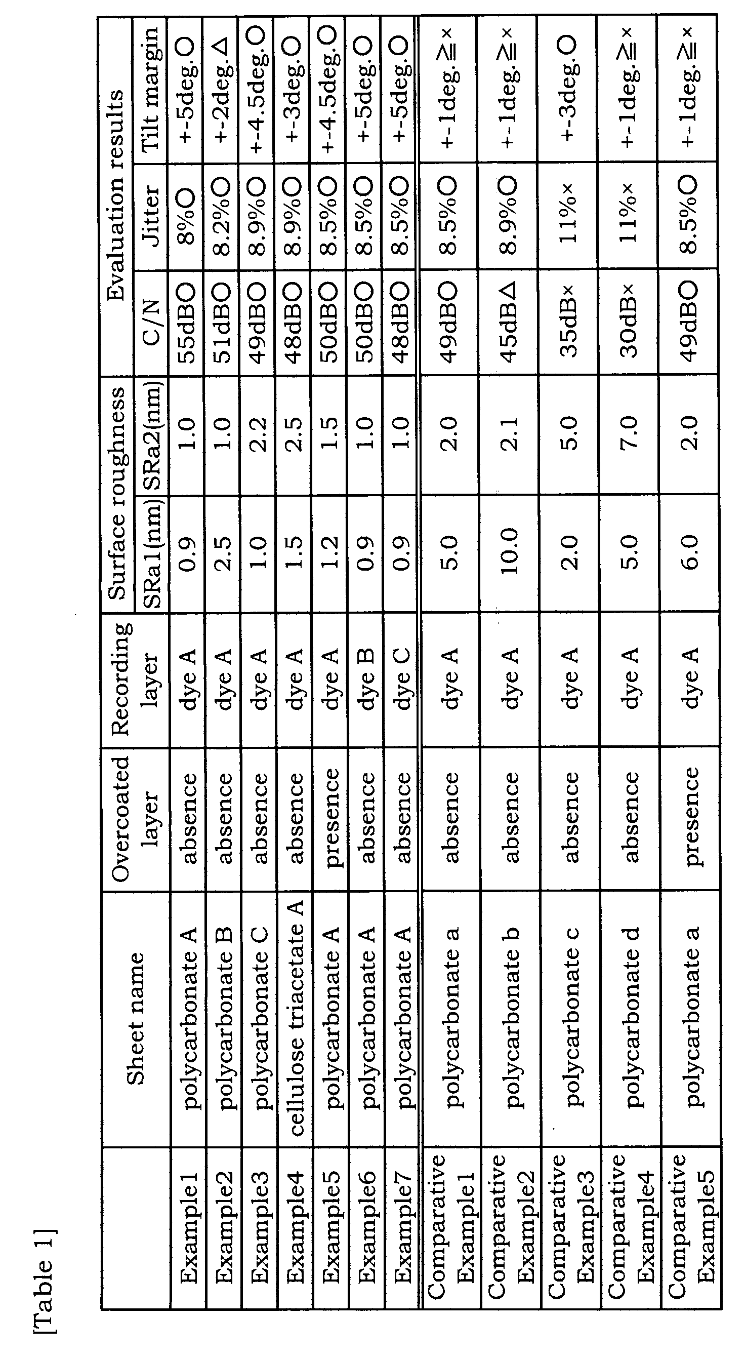
- Table 1 shows that all of the C/N, jitter, and tilt margin were made preferable by limiting SRa1 and SRa2 to 3.0 nm or less.
- On the other hand, in the case of Comparative Example 1, 2, 4, and 5 where SRa1 exceeds 3.0, the tilt margin was found out undesirable. Also in the case of Comparative Example 3 and 4 where SRa2 exceeds 3.0, the C/N and jitter were found out undesirable.
- Using a substrate made of extrusion molded polycarbonate resin (trade name: Panlite AD 5503, polycarbonate manufactured by Teijin Chemical Industry Co., Ltd.) and having a thickness of 1.1 mm and a spiral groove with a diameter of 120 mm (the depth 100 nm; the width 0.120 µm, and the track pitches 300 nm), Ag was sputtered on the face of the substrate having the groove to form a light reflective layer with a film thickness of 100 nm, and after that, a dye coating solution produced by dissolving an Orasol Blue GN (manufactured by Ciba Speciality Chemical Co.; the maximum absorption wavelength: 340 nm) as a dye A in 2,2,3,3-tetrafluoropropanol by mixing them by ultrasonic wave vibration for 2 hours was applied to the resulting substrate by a spin coating method while the rotation speed being changed from 300 rpm to 4,000 rpm under the conditions of 23°C and 50% RH. After that, the substrate was kept at 23°C and 50% RH for 1 hour and further an ultraviolet ray-curable adhesive (SD-347, manufactured by Dainippon Ink and Chemicals, Incorporated; the solubility of the dye 0.05 % by weight) was applied by a spin coating method at 100 to 300 rpm and as a sheet for the cover layer, a cellulose triacetate film B (Fujitac, manufactured by Fuji Photo Film Co., Ltd.) with a film thickness of 80 µm and adjusted so as to have the projection in number shown in Table 2 was laminated thereon, and after the ultraviolet ray-curable adhesive was spread to the entire surface by changing the rotation speed from 300 rpm to 4,000 rpm, ultraviolet rays were radiated from an ultraviolet lamp to cure the adhesive and obtain a sample (optical information recording medium)
- Incidentally, the number of the projections with a height of 20 nm or higher and the number of the projections with a height of 100 nm or higher per 30 µm2 square in the cover layer surface of the above-described sample (optical information recording medium) were measured by an atomic force microscope (AFM) and the details were as follows:
-
- Apparatus: SPA 500 manufactured by Seiko Instruments Inc.
- Mode: AFM mode (contact mode)
- Probe for measurement: SI AF01 (spring constant: 0.1 N/m)
- Measurement range: 10 µm square
- Scanning lines: 512 × 512
- Scanning speed: 2 Hz
-
- The foregoing produced optical information recording medium was subjected to reproduction repeated 1,000 times using a reproducing evaluation apparatus (DDU1000, manufactured by Pulstec Industrial Co., Ltd.) incorporated with laser of 405 nm wavelength and pickup with NA of 0.85. The increase of the jitter was measured and the scratches on the disc surface were observed by eye observation at that time. The results were shown in Table 2.
- An optical information recording medium was produced in the same manner as Example 8 except that a cellulose triacetate film C produced by forming a mat layer containing silica as a mat agent and cellulose triacetate as a binder on cellulose triacetate C (Fujitac, manufactured by Fuji Photo Film Co., Ltd.) and adjusted so as to have the projections in number as shown in Table 2 was used in place of the cellulose triacetate film B used in Example 8 and the same measurement and evaluation were carried out. The results were shown in Table 2.
- An optical information recording medium was produced by forming an overcoated layer adjusted so as to have the projections in number as shown in Table 2 on the cover layer of Example 8 by applying an ultraviolet ray-curable adhesive (SD-347, manufactured by Dainippon Ink and Chemicals, Incorporated) by a spin coating method at 100 to 300 rpm, spreading the adhesive to the entire surface by changing the rotation speed from 300 rpm to 4,000 rpm, and then radiating ultraviolet rays from an ultraviolet lamp to cure the adhesive and the same measurement and evaluation were carried out. The results were shown in Table 2.
- An optical information recording medium was produced in the same manner as Example 8 except that a cellulose triacetate film D (the same one as the cover layer used in Example 9 except that no mat layer was formed) adjusted so as to have the projections in number as shown in Table 2 was used in place of the cellulose triacetate film B used in Example 8 and the same measurement and evaluation were carried out. The results were shown in Table 2.
- An optical information recording medium was produced in the same manner as Example 8 except that a 80 µm-thick polycarbonate film (trade name: Panlite PC 2151, manufactured by Teijin Chemical Industry Co., Ltd.) adjusted so as to have the projections in number as shown in Table 2 was used in place of the cellulose triacetate film B used in Example 8 and the same measurement and evaluation were carried out. The results were shown in Table 2.
- An optical information recording medium was produced by forming an overcoated layer adjusted so as to have the projections in number as shown in Table 2 on the cover layer of Example 8 by applying an ultraviolet ray-curable adhesive (SD-347, manufactured by Dainippon Ink and Chemicals, Incorporated) by a spin coating method at 100 to 300 rpm, spreading the adhesive to the entire surface by changing the rotation speed from 300 rpm to 4,000 rpm, and then radiating ultraviolet rays from an ultraviolet lamp to cure the adhesive and the same measurement and evaluation were carried out. The results were shown in Table 2.

- Table 2 shows that in the case of Example having the projections in a predetermined number was found excellent in the jitter property after reproduction 1,000 times and hardly scratched.
- Using a substrate made of extrusion molded polycarbonate resin (trade name: Panlite AD 5503, polycarbonate manufactured by Teijin Chemical Industry Co., Ltd.) and having a thickness of 1.1 mm and a spiral groove with a diameter of 120 mm (the depth 100 nm; the width 0.120 µm, and the track pitches 300 nm), Ag was sputtered on the face of the substrate having the groove to form a light reflective layer with a film thickness of 100 nm.
- After that, a dye coating solution was produced by dissolving a dye A, a phthalocyanine-based organic compound, (Orasol Blue GN: manufactured by Ciba Speciality Chemical Co.; the maximum absorption wavelength: 340 nm, 640 nm) in 2,2,3,3-tetrafluoropropanol by mixing them by ultrasonic wave vibration for 2 hours and the produced coating solution was applied to the reflecting layer by a spin coating method while the rotation speed being changed from 300 rpm to 4,000 rpm under the conditions of 23°C and 50% RH. After that, the substrate was kept at 23°C and 50% RH for 1 to 4 hours to dry and form a recording layer (thickness: 100 nm).
- After that, an ultraviolet ray-curable adhesive (SD-347, manufactured by Dainippon Ink and Chemicals, Incorporated; the solubility of the dye 0.05 % by weight) was applied to the recording layer by a spin coating method at 100 to 300 rpm and a polycarbonate sheet (the thickness: 0.07 mm, trade name: Pure Ace, manufactured by Teijin Ltd.) was laminated thereon, and after the ultraviolet ray-curable adhesive was spread to the entire surface by changing the rotation speed from 300 rpm to 4,000 rpm, ultraviolet rays were radiated from an ultraviolet lamp to cure the adhesive so as to form a protective layer and thus a sample (optical information recording medium) was produced.
- Recording and reproducing was carried out in the land part (the convex part observed from the protective layer side).
- A sample of optical information recording medium of Example 12 was produced in the same manner as Example 11, except that the height of the land part of the substrate was 20 nm instead of 60 nm in the Example 11.
- A sample of optical information recording medium of Example 13 was produced in the same manner as Example 11, except that the height of the land part of the substrate was 100 nm instead of 60 nm in the Example 11.
- A sample of optical information recording medium of Example 14 was produced in the same manner as Example 11, except that the width of the land part of the substrate was 220 nm instead of 120 nm in the Example 11.
- A sample of optical information recording medium of Example 15 was produced in the same manner as Example 11, except that the width of the land part of the substrate was 80 nm instead of 120 nm in the Example 11.
- A sample of optical information recording medium of Example 16 was produced in the same manner as Example 11, except that the dropwise titrating amount of the ultraviolet ray-curable adhesive and the rotation pattern of the spin coating were changed so as to adjust the thickness of the ultraviolet ray-curable adhesive layer to be 50 µm instead of 30 µm in the Example 11.
- A sample of optical information recording medium of Example 17 was produced in the same manner as Example 11, except that the dropwise titrating amount of the ultraviolet ray-curable adhesive and the rotation pattern of the spin coating were changed so as to adjust the thickness of the ultraviolet ray-curable adhesive layer to be 5 µm instead of 30 µm in the Example 11.
- A sample of optical information recording medium of Example 18 was produced in the same manner as Example 11, except that a benzotriazol-based dye (dye D) defined as follows was used as the dye instead of the dye A in the Example 11.

- A sample of optical information recording medium of Example 19 was produced in the same manner as Example 11, except that an aminobutadiene-based dye (dye E) defined as follows was used as the dye instead of the dye A in the Example 11.

- Recording and reproducing was carried out in the same manner as Example 11, except that the recording and reproducing was carried out in the groove part (the groove part observed from the protective layer side).
- A sample of optical information recording medium of Comparative Example 10 was produced in the same manner as Example 11, except that the height of the land part of the substrate was 120 nm instead of 60 nm in the Example 11.
- A sample of optical information recording medium of Comparative Example 11 was produced in the same manner as Example 11, except that the height of the land part of the substrate was 10 nm instead of 60 nm in the Example 11.
- A sample of optical information recording medium of Comparative Example 12 was produced in the same manner as Example 11, except that the width of the land part of the substrate was 240 nm instead of 120 nm in the Example 11.
- A sample of optical information recording medium of Comparative Example 13 was produced in the same manner as Example 11, except that the width of the land part of the substrate was 60 nm instead of 120 nm in the Example 11.
- A sample of optical information recording medium of Comparative Example 14 was produced in the same manner as Example 11, except that the thickness of the ultraviolet ray-curable adhesive layer was adjusted to be 80 µm instead of 30 µm in the Example 11.
- A sample of optical information recording medium of Comparative Example 15 was produced in the same manner as Example 11, except that the thickness of the ultraviolet ray-curable adhesive layer was adjusted to be 3 µm instead of 30 µm in the Example 11.
- Using a substrate made of extrusion molded polycarbonate resin (trade name: Panlite AD 5503, polycarbonate manufactured by Teijin Chemical Industry Co., Ltd.) and having a thickness of 1.1 mm and a spiral groove with a diameter of 120 mm (the depth 100 nm; the width 0.120 µm, and the track pitches 300 nm), a light reflective layer (Ag: thickness of 100 nm), an under part heat resistant protective layer (ZnS-SiO2: thickness of 170 nm), a recording layer (AgInSbTe; thickness of 25 nm), and an upper part heat resistant protective layer (ZnS-SiO2: thickness of 35 nm) were formed in this order by a sputtering method.
- After that, an ultraviolet ray-curable adhesive (SD-347, manufactured by Dainippon Ink and Chemicals, Incorporated; the solubility in the organic compounds 0.05 % by weight) was applied to the upper part heat resistant protective layer by a spin coating method at 100 to 300 rpm and a polycarbonate sheet (the thickness: 0.07 mm, trade name: Pure Ace, manufactured by Teijin Ltd.) was laminated thereon, and after the ultraviolet ray-curable adhesive was spread to the entire surface by changing the rotation speed from 300 rpm to 4,000 rpm, ultraviolet rays were radiated from an ultraviolet lamp to cure the adhesive and produce a sample (optical information recording medium) was produced.
- Recording and reproducing was carried out in the groove part (the concave part observed from the protective layer side).
- Using the sample employed in Comparative Example 16, recording and reproducing was carried out in the land part.
- Using each produced optical information recording medium, 1-7 PP modulated signals (laser power 6 mW) were recorded and regenerated by employing a recording and reproducing evaluation apparatus (DDU1000, manufactured by Pulstec Industrial Co., Ltd.) incorporated with laser of 405 nm and pickup with NA of 0.85 in the conditions of clock frequency of 66 MHz/(linear velocity of 5.6 m/s) and jitter was measured by a time interval analyzer.
- Using each produced optical information recording medium, single frequency signals (2T = 0.13 µm) were recorded and regenerated by employing a recording and reproducing evaluation apparatus (DDU1000, manufactured by Pulstec Industrial Co., Ltd.) incorporated with laser of 405 nm and pickup with NA of 0.85 in the conditions of clock frequency of 66 MHz/(linear velocity of 5.6 m/s) and the C/N was measured by a spectral analyzer.
- Using each produced optical information recording medium, 1-7 PP modulated signals (laser power 6 mW) were recorded by employing a recording and reproducing evaluation apparatus (DDU1000, manufactured by Pulstec Industrial Co., Ltd.) incorporated with laser of 405 nm and pickup with NA of 0.85 in the conditions of clock frequency of 66 MHz/(linear velocity of 5.6 m/s) and regenerated (laser power 0.4 mW) 1,000,000 times in the still mode and the modulation deterioration after the 1,000,000 times reproducing was measured on the basis of 100% as the modulation factor at the beginning.
- The evaluation results were shown in Table 3.
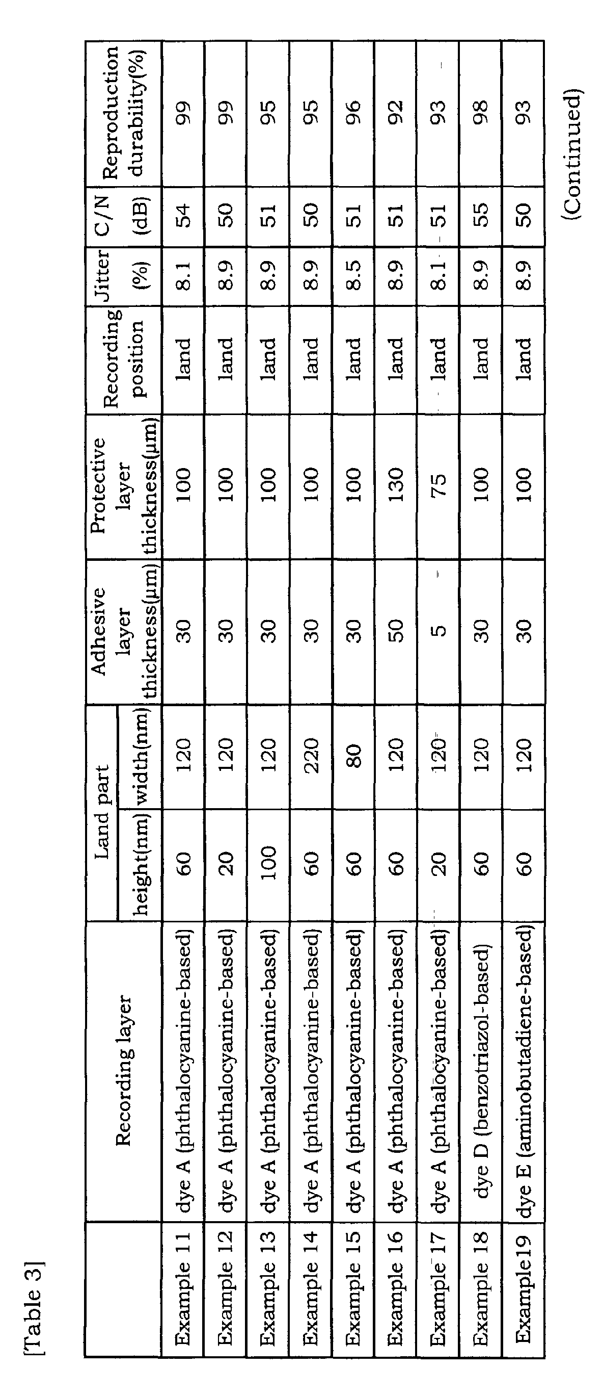
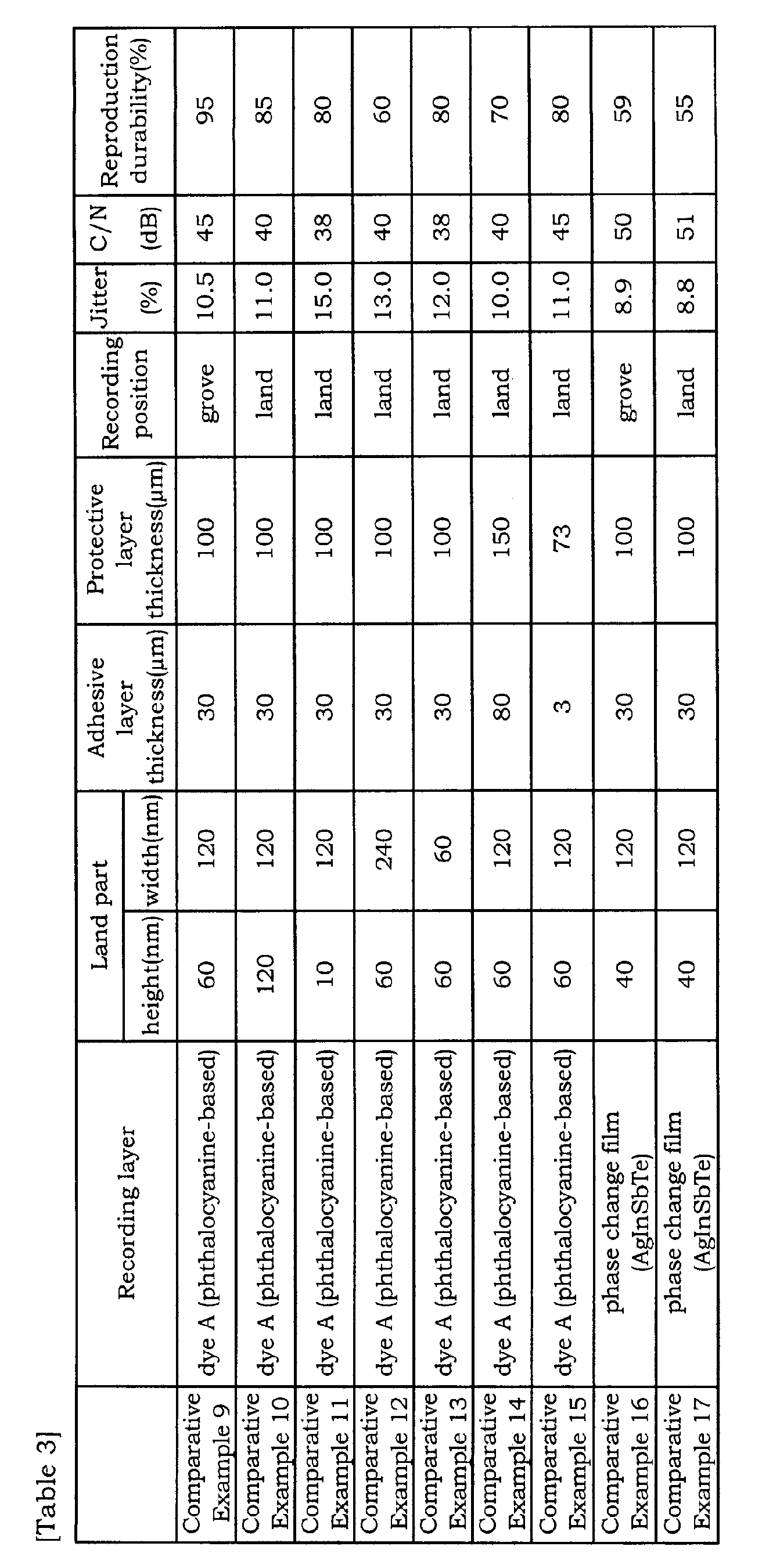
- According to Table 3, the jitter, C/N, and reproduction durability of each optical information recording medium of Example were found excellent, whereas the jitter, C/N, and reproduction durability of each optical information recording medium of Comparative Example were found inferior.
- The invention can provide an optical information recording medium excellent in high density recording properties, further an optical information recording medium with excellent jitter and improved scratch-proofing property of the disc surface, and furthermore an excellent optical information recording medium comprising an organic dye-containing recording layer and scarcely causing reproduction deterioration, RF output decrease, C/N decrease, and jitter decrease in DVR-Blue system.
Claims (22)
- An optical information recording medium comprising a substrate including a groove with a track pitch of 200 to 400 nm and a groove depth of 20 to 150 nm and having successively disposed on a surface thereof a light reflective layer, a recording layer containing a dye in which information is recorded by irradiation with a laser beam having a wavelength of no greater than 450 nm, an adhesive layer, and a cover layer with a thickness of 0.01 to 0.5 mm, wherein a surface of the optical information recording medium on a side disposed with the cover layer has a center surface average roughness (SRa1) of no greater than 3.0 nm when measured over a large surface area and a center surface average roughness (SRa2) of no greater than 3.0 nm when measured over a minute surface area.
- The optical information recording medium of claim 1, further comprising at least one overcoated layer, containing a radiation-curable resin, disposed on the cover layer.
- The optical information recording medium of claim 1, wherein the surface on the side disposed with the cover layer has a center surface average roughness (SRa1) of no greater than1.5 nm when measured over a large surface area and a center surface average roughness (SRa2) of no greater than 1.5 nm when measured over a minute surface area.
- The optical information recording medium of claim 2, wherein the radiation-curable resin contained in the overcoated layer is selected from the group consisting of acrylate compounds, acrylamides, methacrylate compounds, methacrylic acid amides, vinyl ethers, and vinyl esters.
- An optical information recording medium comprising a substrate including a groove with a track pitch of 200 to 400 nm and a groove depth of 20 to 150 nm and having successively disposed on a surface thereof a light reflective layer, a recording layer on which information is recorded by irradiation with a laser beam having a wavelength of no greater than 450 nm, an adhesive layer containing an adhesive, and a cover layer with a thickness of 0.01 to 0.5 mm, wherein a surface of the cover layer has at least 15 projections with a height of at least 20 nm per 30 µm2 and 1 to 5 of the projections have a height of at least 100 nm.
- The optical information recording medium of claim 1 or 5, wherein the substrate contains at least one substance selected from the group consisting of glass, polycarbonate, acrylic resin, polyvinyl chloride, vinyl chloride-based resin, epoxy resin, amorphous polyolefin, polyester, and aluminum.
- The optical information recording medium of claim 1 or 5, further comprising an undercoated layer disposed on the substrate surface of the side disposed with the light reflective layer.
- The optical information recording medium of claim 1 or 5, wherein the light reflective layer contains at least one light reflecting substance selected from the group consisting of Mg, Se, Y, Ti, Zr, Hf, V, Nb, Ta, Cr, Mo, W, Mn, Re, Fe, Co, Ni, Ru, Rh, Pd, Ir, Pt, Cu, Ag, Au, Zn, Cd, Al, Ga, In, Si, Ge, Te, Pb, Po, Sn, Bi and stainless steel.
- The optical information recording medium of claim 1 or 5, wherein the dye contained in the recording layer has one or more maximum absorption peaks, at least one of which has a maximum absorption wavelength of no greater than 400 nm.
- The optical information recording medium of claim 1 or 5, wherein the dye contained in the recording layer is selected from the group consisting of a cyanine dye, an oxonol dye, a metal complex-based dye, an azo dye, and a phthalocyanine dye.
- The optical information recording medium of claim 1 or 5, wherein the cover layer contains at least one substance selected from the group consisting of polycarbonate, cellulose triacetate, and polyethylene terephthalate.
- The optical information recording medium of claim 5, wherein the surface of the cover layer has 15 to 100 projections with a height of at least 20 nm per 30 µm2 and 1 to 4 of the projections have a height of 100 nm or higher.
- An optical information recording medium comprising a substrate including a land with a track pitch of 200 to 400 nm, a land height of 20 to 100 nm, and a land width of 80 to 220 nm and having successively disposed on a surface thereof at least a light reflective layer, a recording layer containing an organic dye, and a protection layer, wherein the protection layer has a thickness of 75 to 130 µm and recording and reproducing are carried out on the land through the protection layer using a laser beam with a wavelength of no greater than 450 nm and an objective lens with a numerical aperture (NA) of no less than 0.7.
- The optical information recording medium of claim 13, wherein the land of the substrate has a track pitch of 260 to 340 nm, a land height of 30 to 80 nm, and a land width of 120 to 180 nm.
- The optical information recording medium of claim 13, wherein the substrate contains at least one substance selected from the group consisting of polycarbonate, acrylic resin, polyvinyl chloride, vinyl chloride-based resin, epoxy resin, amorphous polyolefin, and polyester.
- The optical information recording medium of claim 13, further comprising an undercoated layer disposed on the substrate surface of the side disposed with the light reflective layer.
- The optical information recording medium of claim 13, wherein the light reflective layer contains at least one light reflecting substance selected from the group consisting of Mg, Se, Y, Ti, Zr, Hf, V, Nb, Ta, Cr, Mo, W, Mn, Re, Fe, Co, Ni, Ru, Rh, Pd, Ir, Pt, Cu, Ag, Au, Zn, Cd, Al, Ga, In, Si, Ge, Te, Pb, Po, Sn, Bi and stainless steel.
- The optical information recording medium of claim 13, wherein the dye contained in the recording layer is selected from the group consisting of phthalocyanine-based dyes, benzotriazole-based dyes, and aminobutadiene-based dyes.
- The optical information recording medium of claim 13, wherein the protection layer comprises an adhesive layer, disposed on the recording layer, and a cover film, attached to the recording layer via the adhesive layer.
- The optical information recording medium of claim 13, wherein the protection layer is formed by providing a curable resin on the recording layer and curing the resin.
- The optical information recording medium of claim 13, wherein the recording layer is further disposed with a sputtered layer on one or both sides thereof.
- The optical information recording medium of claim 13, further comprising an auxiliary protection layer disposed on the protection layer.
Applications Claiming Priority (8)
| Application Number | Priority Date | Filing Date | Title |
|---|---|---|---|
| JP2001190402 | 2001-06-22 | ||
| JP2001190402A JP2003006932A (en) | 2001-06-22 | 2001-06-22 | Optical information recording medium |
| JP2001262814 | 2001-08-31 | ||
| JP2001262814A JP4213371B2 (en) | 2001-08-31 | 2001-08-31 | Optical information recording medium |
| JP2001267684 | 2001-09-04 | ||
| JP2001267684 | 2001-09-04 | ||
| JP2001276915 | 2001-09-12 | ||
| JP2001276915A JP4220695B2 (en) | 2001-09-04 | 2001-09-12 | Optical information recording medium |
Publications (1)
| Publication Number | Publication Date |
|---|---|
| EP1271499A2 true EP1271499A2 (en) | 2003-01-02 |
Family
ID=27482367
Family Applications (1)
| Application Number | Title | Priority Date | Filing Date |
|---|---|---|---|
| EP02013808A Withdrawn EP1271499A2 (en) | 2001-06-22 | 2002-06-21 | Optical information recording medium |
Country Status (3)
| Country | Link |
|---|---|
| US (1) | US7129019B2 (en) |
| EP (1) | EP1271499A2 (en) |
| TW (1) | TWI242206B (en) |
Cited By (12)
| Publication number | Priority date | Publication date | Assignee | Title |
|---|---|---|---|---|
| WO2005021651A1 (en) * | 2003-08-26 | 2005-03-10 | General Electric Company | Substrate and storage media for data prepared therefrom |
| US7029742B2 (en) | 2001-08-31 | 2006-04-18 | General Electric | Storage medium for data |
| US7041780B2 (en) | 2003-08-26 | 2006-05-09 | General Electric | Methods of preparing a polymeric material composite |
| US7129019B2 (en) | 2001-06-22 | 2006-10-31 | Fuji Photo Film Co., Ltd. | Optical information recording medium |
| WO2007067800A3 (en) * | 2005-12-09 | 2007-07-26 | Gen Electric | Storage media and associated method |
| US7309518B2 (en) | 2001-03-29 | 2007-12-18 | General Electric Company | Radial tilt reduced media |
| US7314907B2 (en) | 2003-08-26 | 2008-01-01 | General Electric Company | Purified polymeric materials and methods of purifying polymeric materials |
| US7341820B2 (en) | 2001-11-30 | 2008-03-11 | Fujifilm Corporation | Optical information recording medium |
| US7354990B2 (en) | 2003-08-26 | 2008-04-08 | General Electric Company | Purified polymeric materials and methods of purifying polymeric materials |
| US7384723B2 (en) * | 2002-01-23 | 2008-06-10 | Fujifilm Corporation | Optical information recording medium |
| US7512059B2 (en) | 2003-01-08 | 2009-03-31 | Mitsubishi Kagaku Media Co., Ltd. | Optical information recording medium and process for producing optical information recording medium |
| EP1887390A4 (en) * | 2005-05-27 | 2010-09-15 | Zeon Corp | Grid polarizing film, method for producing grid polarizing film, optical laminate, method for producing optical laminate, and liquid crystal display |
Families Citing this family (19)
| Publication number | Priority date | Publication date | Assignee | Title |
|---|---|---|---|---|
| EP1265233B1 (en) * | 2001-06-04 | 2005-11-23 | Fuji Photo Film Co., Ltd. | Optical information recording medium |
| JP4076739B2 (en) * | 2001-06-13 | 2008-04-16 | 富士フイルム株式会社 | Optical recording medium |
| DE60233511D1 (en) * | 2001-07-18 | 2009-10-08 | Sony Corp | SUBSTRATE FOR USE OF OPTICAL RECORDING / REPRODUCING MEDIUM, MANUFACTURING PROCESS FOR OPTICAL RECORDING / REPRODUCTION MEDIUM, PRODUCTION STAMP AND PRODUCTION STAMP FOR OPTICAL RECORDING / REPRODUCING MEDIUM |
| US20050237909A1 (en) * | 2002-07-24 | 2005-10-27 | Maarten Kuijper | Rewritable optical medium, apparatus for reading and/or for writing it and process for manufacturing a rewritable disc. |
| JP3902523B2 (en) * | 2002-08-05 | 2007-04-11 | 富士フイルム株式会社 | Optical information recording medium and information recording method |
| JP2004098542A (en) * | 2002-09-11 | 2004-04-02 | Tdk Corp | Optical recording medium and optical recording/reproducing method |
| CN100341059C (en) * | 2002-12-19 | 2007-10-03 | 富士胶片株式会社 | Optical information recording method and optical information recording medium |
| US20050166218A1 (en) * | 2002-12-24 | 2005-07-28 | Fujitsu Limited | Magneto-optical recording medium and method for producing the same |
| EP1647013B1 (en) * | 2003-07-11 | 2012-05-23 | Koninklijke Philips Electronics N.V. | Recordable optical record carrier |
| TWI265513B (en) * | 2003-07-25 | 2006-11-01 | Tdk Corp | Optical recording medium and method of producing the same |
| KR20060057607A (en) * | 2003-08-12 | 2006-05-26 | 코닌클리케 필립스 일렉트로닉스 엔.브이. | How to record information on recorders, discs, and discs |
| JP4313648B2 (en) * | 2003-11-05 | 2009-08-12 | Tdk株式会社 | Optical recording medium and manufacturing method thereof |
| JP2005174408A (en) * | 2003-12-09 | 2005-06-30 | Fuji Photo Film Co Ltd | Optical information recording medium, its manufacturing method, and method of recording optical information |
| DE602007010092D1 (en) * | 2006-01-13 | 2010-12-09 | Mitsubishi Kagaku Media Co Ltd | OPTICAL RECORDING MEDIUM |
| JP2008010107A (en) * | 2006-06-30 | 2008-01-17 | Toshiba Corp | Information recording medium and disk device |
| JP5834554B2 (en) * | 2011-07-07 | 2015-12-24 | ソニー株式会社 | Optical recording medium |
| CN105246699B (en) | 2013-05-27 | 2018-07-24 | 富士胶片株式会社 | Recording materials and optical information recording medium |
| US9548419B2 (en) | 2014-05-20 | 2017-01-17 | Southern Taiwan University Of Science And Technology | Light emitting diode chip having multi microstructure substrate surface |
| WO2017132169A1 (en) * | 2016-01-28 | 2017-08-03 | Siemens Healthcare Diagnostics Inc. | Methods and apparatus for detecting an interferent in a specimen |
Family Cites Families (74)
| Publication number | Priority date | Publication date | Assignee | Title |
|---|---|---|---|---|
| JPS5856239A (en) | 1981-09-28 | 1983-04-02 | Tdk Corp | Optical recording medium |
| JPS5856892A (en) | 1981-10-01 | 1983-04-04 | Ricoh Co Ltd | optical information recording medium |
| US4465767A (en) * | 1981-11-27 | 1984-08-14 | Ricoh Company, Ltd. | Optical information recording medium |
| JPS60204395A (en) | 1984-03-29 | 1985-10-15 | Tdk Corp | Optical recording medium |
| JPH0440947Y2 (en) | 1987-07-29 | 1992-09-25 | ||
| JPH02196689A (en) | 1989-01-26 | 1990-08-03 | Toray Ind Inc | Optical recording medium |
| US5075145A (en) | 1989-04-07 | 1991-12-24 | Fuji Photo Film Co., Ltd. | Optical recording medium |
| US5340698A (en) | 1989-05-02 | 1994-08-23 | Tdk Corporation | Optical disk |
| JPH0464936A (en) * | 1990-07-04 | 1992-02-28 | Canon Inc | Optical recording medium |
| CA2047163C (en) | 1990-07-20 | 1995-05-16 | Kenji Ohta | Optical disk |
| JPH0644608A (en) | 1992-02-21 | 1994-02-18 | Nippon Columbia Co Ltd | Optical information recording medium |
| JP3315157B2 (en) | 1992-08-27 | 2002-08-19 | パイオニア株式会社 | Information recording medium |
| US6051289A (en) | 1993-02-12 | 2000-04-18 | Nippon Petrochemicals, Co., Ltd | Liquid crystalline polymer film, laminate sheet for optical element using same, and optical element using the laminate |
| EP0627734A1 (en) | 1993-06-04 | 1994-12-07 | Canon Kabushiki Kaisha | Process for manufacturing optical recording medium |
| EP0653685A1 (en) | 1993-11-16 | 1995-05-17 | Agfa-Gevaert N.V. | Methods for producing lithographic plates with imaging elements comprising a photopolymerizable composition |
| US5747413A (en) | 1994-01-28 | 1998-05-05 | Ricoh Company, Ltd. | Reversible thermosensitive recording material and method of forming and erasing images |
| JPH07266703A (en) | 1994-03-31 | 1995-10-17 | Ricoh Co Ltd | Optical recording medium and method of making information recording disc using the same |
| US5968708A (en) | 1994-04-20 | 1999-10-19 | Ricoh Company, Ltd. | Optical recording medium and method of producing the same |
| US5763868A (en) | 1994-07-25 | 1998-06-09 | Dai Nippon Printing Co., Ltd. | Optical card |
| JP3496282B2 (en) * | 1994-08-01 | 2004-02-09 | 東ソー株式会社 | Magneto-optical disk media |
| US5798161A (en) | 1995-01-20 | 1998-08-25 | Dai Nippon Printing Co., Ltd. | Optical disk, method of forming image on optical disk, image forming apparatus and adhesive layer transfer sheet |
| JPH09147418A (en) | 1995-11-17 | 1997-06-06 | Taiyo Yuden Co Ltd | Optical information recording medium |
| US5962181A (en) | 1996-04-23 | 1999-10-05 | Agfa-Gevaert, N.V. | Process for the preparation of a metal heat mode recording element |
| JPH09326136A (en) | 1996-06-05 | 1997-12-16 | Sony Corp | Optical recording medium and manufacturing method thereof |
| US5922504A (en) | 1996-10-16 | 1999-07-13 | Eastman Kodak Company | Optical recording elements having recording layers containing mixtures of no k metallized formazan and cyanine dyes |
| JP4571238B2 (en) | 1996-12-24 | 2010-10-27 | コーニンクレッカ フィリップス エレクトロニクス エヌ ヴィ | Optical recording medium having phase change recording layer |
| JPH10326435A (en) * | 1997-03-25 | 1998-12-08 | Sony Corp | Optical recording medium and optical disk device |
| JPH10283672A (en) | 1997-04-08 | 1998-10-23 | Sony Corp | Optical recording medium |
| JPH10289479A (en) | 1997-04-10 | 1998-10-27 | Tdk Corp | Optical recording medium |
| JPH10302310A (en) * | 1997-04-25 | 1998-11-13 | Sony Corp | Optical recording medium and optical disk device |
| JP4099549B2 (en) | 1997-05-16 | 2008-06-11 | ソニー株式会社 | Optical recording medium and optical disk device |
| US6353592B1 (en) * | 1997-06-27 | 2002-03-05 | Sony Corporation | Optical recording medium and optical disk device |
| JPH11120617A (en) | 1997-10-17 | 1999-04-30 | Sony Corp | Optical recording medium |
| JPH11138993A (en) | 1997-11-11 | 1999-05-25 | Matsushita Electric Ind Co Ltd | Optical recording medium and optical recording / reproducing method |
| US5882760A (en) | 1997-11-17 | 1999-03-16 | Eastman Kodak Company | Recordable optical disks with metallic interlayer |
| JPH11195243A (en) | 1997-12-26 | 1999-07-21 | Sony Corp | Multilayer optical disc and recording / reproducing device |
| US6136751A (en) | 1998-01-29 | 2000-10-24 | Ricoh Company, Ltd. | Reversible thermosensitive recording medium, and image forming and erasing method |
| JP2000030257A (en) | 1998-07-08 | 2000-01-28 | Taiyo Yuden Co Ltd | Optical information medium and its recording medium |
| TW411436B (en) * | 1998-08-18 | 2000-11-11 | Ind Tech Res Inst | Improved structure of optically recordable media and its manufacture method |
| JP2000067468A (en) | 1998-08-25 | 2000-03-03 | Teijin Ltd | Optical disk and method of manufacturing the same |
| JP3671126B2 (en) | 1999-03-19 | 2005-07-13 | Tdk株式会社 | Optical information medium and manufacturing method thereof |
| JP2000285520A (en) | 1999-03-29 | 2000-10-13 | Sony Corp | Optical disk and method of manufacturing optical disk |
| EP1047055A1 (en) | 1999-04-22 | 2000-10-25 | 3M Innovative Properties Company | Optical storage medium |
| JP2000311392A (en) | 1999-04-28 | 2000-11-07 | Sony Corp | Optical disc and method of manufacturing the same |
| EP1065663A3 (en) | 1999-06-30 | 2002-02-06 | Sony Corporation | Optical recording medium |
| TW561115B (en) | 1999-09-08 | 2003-11-11 | Fuji Photo Film Co Ltd | Optical information recording medium |
| US6269072B1 (en) | 1999-10-22 | 2001-07-31 | Victor Company Of Japan, Ltd. | Optical disc |
| JP2001155383A (en) | 1999-11-26 | 2001-06-08 | Sony Corp | Optical recording medium |
| WO2001040329A1 (en) | 1999-11-30 | 2001-06-07 | Daicel Chemical Industries, Ltd. | Lowly lactone-modified reactive monomer composition, acrylic polyol resins produced with the same, curable resin compositions and coating compositions |
| JP2001243658A (en) | 1999-12-21 | 2001-09-07 | Teijin Ltd | Plastic film and wound layer for transparent protective layer of optical disk |
| US7050385B2 (en) * | 2000-02-08 | 2006-05-23 | Tosoh Corporation | Optical recording medium |
| JP4164984B2 (en) | 2000-03-27 | 2008-10-15 | ソニー株式会社 | Optical recording medium |
| JP2001344824A (en) | 2000-03-30 | 2001-12-14 | Tdk Corp | Method for producing optical recording medium and optical recording medium |
| JP2002157737A (en) | 2000-05-12 | 2002-05-31 | Tdk Corp | Optical recording method and optical recording medium |
| US6506469B2 (en) * | 2000-05-26 | 2003-01-14 | Tosoh Corporation | Surface-side reproduction type optical recording medium |
| JP2002260280A (en) | 2000-06-28 | 2002-09-13 | Tdk Corp | Optical information medium and evaluation method thereof |
| US6627288B1 (en) * | 2000-08-10 | 2003-09-30 | Mitsui Chemicals, Inc. | Optical recording medium and porphycene compound |
| EP1323160A1 (en) | 2000-09-21 | 2003-07-02 | Bayer Aktiengesellschaft | Optical data carrier containing a phthalocyanine colouring agent as a light absorbing compound in the information layer |
| JP4111666B2 (en) | 2000-09-21 | 2008-07-02 | 富士フイルム株式会社 | Manufacturing method of optical information recording medium |
| JP4239403B2 (en) | 2000-12-06 | 2009-03-18 | ソニー株式会社 | optical disk |
| JP3564664B2 (en) | 2000-12-28 | 2004-09-15 | 北野エンジニアリング株式会社 | Method for manufacturing optical disk composed of single disk, four-layer adhesive sheet used therefor, and wound body thereof |
| US7067029B2 (en) | 2000-12-28 | 2006-06-27 | Kitano Engineering Co., Ltd. | Method for manufacturing an optical disc including a single layered disc and a four layered adhesive sheet member for use therein as well as a rolled member thereof |
| TWI227478B (en) * | 2001-04-26 | 2005-02-01 | Fuji Photo Film Co Ltd | Optical information recording medium |
| EP1265233B1 (en) | 2001-06-04 | 2005-11-23 | Fuji Photo Film Co., Ltd. | Optical information recording medium |
| JP2002367227A (en) | 2001-06-04 | 2002-12-20 | Fuji Photo Film Co Ltd | Optical information recording medium |
| JP4076739B2 (en) * | 2001-06-13 | 2008-04-16 | 富士フイルム株式会社 | Optical recording medium |
| TWI242206B (en) | 2001-06-22 | 2005-10-21 | Fuji Photo Film Co Ltd | Optical information recording medium |
| US7241549B2 (en) | 2001-09-18 | 2007-07-10 | Ricoh Company, Ltd. | Information recording medium |
| JP2003187498A (en) | 2001-10-12 | 2003-07-04 | Fuji Photo Film Co Ltd | Optical information recording medium |
| US7341820B2 (en) | 2001-11-30 | 2008-03-11 | Fujifilm Corporation | Optical information recording medium |
| TWI254305B (en) | 2001-12-14 | 2006-05-01 | Fuji Photo Film Co Ltd | Method of manufacturing optical information recording media |
| EP1843337B1 (en) | 2002-01-23 | 2009-03-25 | FUJIFILM Corporation | Optical information recording medium |
| JP2003331472A (en) * | 2002-03-07 | 2003-11-21 | Fuji Photo Film Co Ltd | Optical information recording medium |
| CN100341059C (en) | 2002-12-19 | 2007-10-03 | 富士胶片株式会社 | Optical information recording method and optical information recording medium |
-
2002
- 2002-06-20 TW TW091113477A patent/TWI242206B/en not_active IP Right Cessation
- 2002-06-21 EP EP02013808A patent/EP1271499A2/en not_active Withdrawn
- 2002-06-21 US US10/176,088 patent/US7129019B2/en not_active Expired - Fee Related
Cited By (15)
| Publication number | Priority date | Publication date | Assignee | Title |
|---|---|---|---|---|
| US7309518B2 (en) | 2001-03-29 | 2007-12-18 | General Electric Company | Radial tilt reduced media |
| US7129019B2 (en) | 2001-06-22 | 2006-10-31 | Fuji Photo Film Co., Ltd. | Optical information recording medium |
| US7314658B2 (en) | 2001-08-31 | 2008-01-01 | General Electric Company | Storage medium for data |
| US7029742B2 (en) | 2001-08-31 | 2006-04-18 | General Electric | Storage medium for data |
| US7341820B2 (en) | 2001-11-30 | 2008-03-11 | Fujifilm Corporation | Optical information recording medium |
| US7384723B2 (en) * | 2002-01-23 | 2008-06-10 | Fujifilm Corporation | Optical information recording medium |
| US7512059B2 (en) | 2003-01-08 | 2009-03-31 | Mitsubishi Kagaku Media Co., Ltd. | Optical information recording medium and process for producing optical information recording medium |
| US7314907B2 (en) | 2003-08-26 | 2008-01-01 | General Electric Company | Purified polymeric materials and methods of purifying polymeric materials |
| WO2005021651A1 (en) * | 2003-08-26 | 2005-03-10 | General Electric Company | Substrate and storage media for data prepared therefrom |
| US7354990B2 (en) | 2003-08-26 | 2008-04-08 | General Electric Company | Purified polymeric materials and methods of purifying polymeric materials |
| US7041780B2 (en) | 2003-08-26 | 2006-05-09 | General Electric | Methods of preparing a polymeric material composite |
| US7585935B2 (en) | 2003-08-26 | 2009-09-08 | Sabic Innovative Plastics Ip B.V. | Purified polymeric materials and methods of purifying polymeric materials |
| EP1887390A4 (en) * | 2005-05-27 | 2010-09-15 | Zeon Corp | Grid polarizing film, method for producing grid polarizing film, optical laminate, method for producing optical laminate, and liquid crystal display |
| US7872803B2 (en) | 2005-05-27 | 2011-01-18 | Zeon Corporation | Grid polarizing film, method for producing the film, optical laminate, method for producing the laminate, and liquid crystal display |
| WO2007067800A3 (en) * | 2005-12-09 | 2007-07-26 | Gen Electric | Storage media and associated method |
Also Published As
| Publication number | Publication date |
|---|---|
| US20030031954A1 (en) | 2003-02-13 |
| TWI242206B (en) | 2005-10-21 |
| US7129019B2 (en) | 2006-10-31 |
Similar Documents
| Publication | Publication Date | Title |
|---|---|---|
| US7129019B2 (en) | Optical information recording medium | |
| EP1369863B1 (en) | Optical information recording medium | |
| EP1239468B1 (en) | Optical information recording medium | |
| EP1267337B1 (en) | Optical recording medium | |
| EP1265233A2 (en) | Optical information recording medium | |
| US6924018B2 (en) | Optical information recording medium | |
| US6959446B2 (en) | Optical information recording medium | |
| US7078084B2 (en) | Optical information recording medium transparent sheet, process for producing the same, and optical information recording medium | |
| US7103897B2 (en) | Optical information recording medium | |
| EP1316951B1 (en) | Optical information recording medium | |
| US20030103443A1 (en) | Optical information recording medium | |
| JP4220695B2 (en) | Optical information recording medium | |
| JP3742021B2 (en) | Optical information recording medium | |
| JP4119688B2 (en) | Optical information recording medium | |
| US20060046015A1 (en) | Optical recording medium and cover sheet for optical recording media | |
| JP2005141804A (en) | Optical recording medium | |
| JP2007226931A (en) | Optical information recording medium and manufacturing method thereof | |
| JP2006236543A (en) | Optical information recording medium and its manufacturing method | |
| JP2006252710A (en) | Optical information recording medium |
Legal Events
| Date | Code | Title | Description |
|---|---|---|---|
| PUAI | Public reference made under article 153(3) epc to a published international application that has entered the european phase |
Free format text: ORIGINAL CODE: 0009012 |
|
| AK | Designated contracting states |
Kind code of ref document: A2 Designated state(s): AT BE CH CY DE DK ES FI FR GB GR IE IT LI LU MC NL PT SE TR |
|
| AX | Request for extension of the european patent |
Free format text: AL;LT;LV;MK;RO;SI |
|
| RAP1 | Party data changed (applicant data changed or rights of an application transferred) |
Owner name: FUJIFILM CORPORATION |
|
| RIC1 | Information provided on ipc code assigned before grant |
Ipc: G11B 7/26 20060101ALI20080626BHEP Ipc: G11B 7/007 20060101ALI20080626BHEP Ipc: G11B 7/24 20060101AFI20021002BHEP |
|
| STAA | Information on the status of an ep patent application or granted ep patent |
Free format text: STATUS: THE APPLICATION HAS BEEN WITHDRAWN |
|
| 18W | Application withdrawn |
Effective date: 20090210 |