EP1270980A1 - Frein à disque notamment pour usage industriel - Google Patents
Frein à disque notamment pour usage industriel Download PDFInfo
- Publication number
- EP1270980A1 EP1270980A1 EP02291509A EP02291509A EP1270980A1 EP 1270980 A1 EP1270980 A1 EP 1270980A1 EP 02291509 A EP02291509 A EP 02291509A EP 02291509 A EP02291509 A EP 02291509A EP 1270980 A1 EP1270980 A1 EP 1270980A1
- Authority
- EP
- European Patent Office
- Prior art keywords
- arms
- opposite
- rod
- disc brake
- lever
- Prior art date
- Legal status (The legal status is an assumption and is not a legal conclusion. Google has not performed a legal analysis and makes no representation as to the accuracy of the status listed.)
- Granted
Links
- 230000007246 mechanism Effects 0.000 claims description 28
- 230000009471 action Effects 0.000 claims description 18
- 230000000295 complement effect Effects 0.000 claims description 7
- 238000006073 displacement reaction Methods 0.000 claims description 5
- 238000006243 chemical reaction Methods 0.000 description 3
- 230000006835 compression Effects 0.000 description 3
- 238000007906 compression Methods 0.000 description 3
- 230000000694 effects Effects 0.000 description 3
- 238000010276 construction Methods 0.000 description 2
- 230000007423 decrease Effects 0.000 description 2
- 238000001514 detection method Methods 0.000 description 2
- 238000010586 diagram Methods 0.000 description 2
- 239000000428 dust Substances 0.000 description 2
- 239000004677 Nylon Substances 0.000 description 1
- 241000826860 Trapezium Species 0.000 description 1
- 210000003323 beak Anatomy 0.000 description 1
- 230000007797 corrosion Effects 0.000 description 1
- 238000005260 corrosion Methods 0.000 description 1
- 230000007547 defect Effects 0.000 description 1
- 230000001419 dependent effect Effects 0.000 description 1
- 230000001627 detrimental effect Effects 0.000 description 1
- 210000005069 ears Anatomy 0.000 description 1
- 229920001971 elastomer Polymers 0.000 description 1
- 239000000806 elastomer Substances 0.000 description 1
- 239000003344 environmental pollutant Substances 0.000 description 1
- 238000009432 framing Methods 0.000 description 1
- 230000005484 gravity Effects 0.000 description 1
- 229920001778 nylon Polymers 0.000 description 1
- 231100000719 pollutant Toxicity 0.000 description 1
- 230000002035 prolonged effect Effects 0.000 description 1
- 230000000630 rising effect Effects 0.000 description 1
- 238000007789 sealing Methods 0.000 description 1
- 230000035945 sensitivity Effects 0.000 description 1
- 238000000926 separation method Methods 0.000 description 1
- 230000035939 shock Effects 0.000 description 1
- 230000007480 spreading Effects 0.000 description 1
Images


Classifications
-
- F—MECHANICAL ENGINEERING; LIGHTING; HEATING; WEAPONS; BLASTING
- F16—ENGINEERING ELEMENTS AND UNITS; GENERAL MEASURES FOR PRODUCING AND MAINTAINING EFFECTIVE FUNCTIONING OF MACHINES OR INSTALLATIONS; THERMAL INSULATION IN GENERAL
- F16D—COUPLINGS FOR TRANSMITTING ROTATION; CLUTCHES; BRAKES
- F16D66/00—Arrangements for monitoring working conditions, e.g. wear, temperature
- F16D66/02—Apparatus for indicating wear
-
- F—MECHANICAL ENGINEERING; LIGHTING; HEATING; WEAPONS; BLASTING
- F16—ENGINEERING ELEMENTS AND UNITS; GENERAL MEASURES FOR PRODUCING AND MAINTAINING EFFECTIVE FUNCTIONING OF MACHINES OR INSTALLATIONS; THERMAL INSULATION IN GENERAL
- F16D—COUPLINGS FOR TRANSMITTING ROTATION; CLUTCHES; BRAKES
- F16D55/00—Brakes with substantially-radial braking surfaces pressed together in axial direction, e.g. disc brakes
- F16D55/02—Brakes with substantially-radial braking surfaces pressed together in axial direction, e.g. disc brakes with axially-movable discs or pads pressed against axially-located rotating members
- F16D55/22—Brakes with substantially-radial braking surfaces pressed together in axial direction, e.g. disc brakes with axially-movable discs or pads pressed against axially-located rotating members by clamping an axially-located rotating disc between movable braking members, e.g. movable brake discs or brake pads
- F16D55/224—Brakes with substantially-radial braking surfaces pressed together in axial direction, e.g. disc brakes with axially-movable discs or pads pressed against axially-located rotating members by clamping an axially-located rotating disc between movable braking members, e.g. movable brake discs or brake pads with a common actuating member for the braking members
- F16D55/2245—Brakes with substantially-radial braking surfaces pressed together in axial direction, e.g. disc brakes with axially-movable discs or pads pressed against axially-located rotating members by clamping an axially-located rotating disc between movable braking members, e.g. movable brake discs or brake pads with a common actuating member for the braking members in which the common actuating member acts on two levers carrying the braking members, e.g. tong-type brakes
-
- F—MECHANICAL ENGINEERING; LIGHTING; HEATING; WEAPONS; BLASTING
- F16—ENGINEERING ELEMENTS AND UNITS; GENERAL MEASURES FOR PRODUCING AND MAINTAINING EFFECTIVE FUNCTIONING OF MACHINES OR INSTALLATIONS; THERMAL INSULATION IN GENERAL
- F16D—COUPLINGS FOR TRANSMITTING ROTATION; CLUTCHES; BRAKES
- F16D65/00—Parts or details
- F16D65/38—Slack adjusters
- F16D65/40—Slack adjusters mechanical
- F16D65/52—Slack adjusters mechanical self-acting in one direction for adjusting excessive play
- F16D65/56—Slack adjusters mechanical self-acting in one direction for adjusting excessive play with screw-thread and nut
- F16D65/567—Slack adjusters mechanical self-acting in one direction for adjusting excessive play with screw-thread and nut for mounting on a disc brake
-
- F—MECHANICAL ENGINEERING; LIGHTING; HEATING; WEAPONS; BLASTING
- F16—ENGINEERING ELEMENTS AND UNITS; GENERAL MEASURES FOR PRODUCING AND MAINTAINING EFFECTIVE FUNCTIONING OF MACHINES OR INSTALLATIONS; THERMAL INSULATION IN GENERAL
- F16D—COUPLINGS FOR TRANSMITTING ROTATION; CLUTCHES; BRAKES
- F16D2121/00—Type of actuator operation force
- F16D2121/005—Type of actuator operation force unspecified force for releasing a normally applied brake
-
- F—MECHANICAL ENGINEERING; LIGHTING; HEATING; WEAPONS; BLASTING
- F16—ENGINEERING ELEMENTS AND UNITS; GENERAL MEASURES FOR PRODUCING AND MAINTAINING EFFECTIVE FUNCTIONING OF MACHINES OR INSTALLATIONS; THERMAL INSULATION IN GENERAL
- F16D—COUPLINGS FOR TRANSMITTING ROTATION; CLUTCHES; BRAKES
- F16D2125/00—Components of actuators
- F16D2125/18—Mechanical mechanisms
- F16D2125/20—Mechanical mechanisms converting rotation to linear movement or vice versa
- F16D2125/22—Mechanical mechanisms converting rotation to linear movement or vice versa acting transversely to the axis of rotation
- F16D2125/26—Cranks
-
- F—MECHANICAL ENGINEERING; LIGHTING; HEATING; WEAPONS; BLASTING
- F16—ENGINEERING ELEMENTS AND UNITS; GENERAL MEASURES FOR PRODUCING AND MAINTAINING EFFECTIVE FUNCTIONING OF MACHINES OR INSTALLATIONS; THERMAL INSULATION IN GENERAL
- F16D—COUPLINGS FOR TRANSMITTING ROTATION; CLUTCHES; BRAKES
- F16D2125/00—Components of actuators
- F16D2125/18—Mechanical mechanisms
- F16D2125/58—Mechanical mechanisms transmitting linear movement
- F16D2125/587—Articulation, e.g. ball-socket
-
- F—MECHANICAL ENGINEERING; LIGHTING; HEATING; WEAPONS; BLASTING
- F16—ENGINEERING ELEMENTS AND UNITS; GENERAL MEASURES FOR PRODUCING AND MAINTAINING EFFECTIVE FUNCTIONING OF MACHINES OR INSTALLATIONS; THERMAL INSULATION IN GENERAL
- F16D—COUPLINGS FOR TRANSMITTING ROTATION; CLUTCHES; BRAKES
- F16D2125/00—Components of actuators
- F16D2125/18—Mechanical mechanisms
- F16D2125/58—Mechanical mechanisms transmitting linear movement
- F16D2125/64—Levers
-
- F—MECHANICAL ENGINEERING; LIGHTING; HEATING; WEAPONS; BLASTING
- F16—ENGINEERING ELEMENTS AND UNITS; GENERAL MEASURES FOR PRODUCING AND MAINTAINING EFFECTIVE FUNCTIONING OF MACHINES OR INSTALLATIONS; THERMAL INSULATION IN GENERAL
- F16D—COUPLINGS FOR TRANSMITTING ROTATION; CLUTCHES; BRAKES
- F16D2125/00—Components of actuators
- F16D2125/18—Mechanical mechanisms
- F16D2125/58—Mechanical mechanisms transmitting linear movement
- F16D2125/70—Rods
Definitions
- the present invention relates generally to brakes disc, especially for industrial use.
- Such safety brakes are more particularly used in industry, for example for the equipment of overhead cranes, winches, transporters, conveyors or others.
- disc brakes the kind comprising two brake pads intended to cooperate with the lateral faces of a disc and which are carried by two jaws.
- Maneuvering means constituted, for example, by means elastics act, most often indirectly, through a articulated structure, on the two jaws to bring them closer to each other and thus causing the two pads to cooperate with the lateral faces of the disc for the braking of it.
- Such operating means are for example of the electrical type, hydraulic or magnetic or of a combined type, such as for example electrohydraulic type.
- the aforementioned elastic means which constitute the clamping means are rated by nominal value so as to ensure the required braking torque.
- a brake shoe carries a friction lining which will wear out on contact with the disc.
- the thickness of the lining decreases over time in correspondence with the prolonged braking action of the disc and the means elastic "elongate", which modifies, in the direction of a decrease, the effort of braking that they are capable of ensuring.
- the present invention relates to a disc brake of the above type in which the wear take-up operation is carried out in a simple manner.
- a disc brake of the above type is characterized in that the rod is provided with two threads, the steps of which are reversed, one with respect to to each other and which cooperate respectively with complementary elements respectively arranged at the end D of the lever located near the end opposite so-called free B of one of the arms, and at the opposite so-called free end B 'of the other arm, so that when the lever is placed in a so-called active position, it rotates, in a so-called active direction, the rod around its axis so as to bring the two arms and therefore the two jaws together.
- a wear take-up mechanism turns the threaded rod around its axis inverted, which tends to bring the carrying arms of the jaws together and so the jaws.
- the wear detector in its active position, rotates a free wheel coupled to the rod and which causes the rotation of the latter.
- the wear detector comprises a pin integral with the freewheel and the lever comprises, at its end D 'opposite to the end D which cooperates with the rod, a part integral with this end opposite D 'and extending in the direction of the rod, a window being formed in said piece to receive the pawn and allow its movement inside said window, from one edge of the window to the opposite edge, during a rotational movement of the lever corresponding to the maximum opening of the jaws.
- the wear detector is found in its active position and moving the pawn, in one direction corresponding to the reverse rotation movement of the lever, rotates the freewheel which in turn causes the rod to rotate.
- the opposite edges of the window are not parallel to each other to ensure consistency in catching up due to pad wear, regardless of the degree of wear.
- the wear detector cooperates with a part of the rod located near one of its ends which is opposite the end cooperating with the lever.
- each jaw is mounted on an arm by through a so-called mounting axis and a link is mounted articulated by its two opposite ends around two pivot axes, one mounted on a tail of the corresponding jaw and the other mounted on a fixed base, the end O, O 'of said arm being mounted for rotation on said base by means of an axis of rotation, all the assembly, pivot and rotation axes being arranged parallel to each other and so as to form a control parallelogram.
- one of the arms carrying the jaw which is the first to move away from the disc when the operating means are actuated to cause a brake release action is connected to a setting mechanism stop mounted with a predetermined clearance corresponding to half of the opening maximum of the two jaws, said mechanism being arranged and dimensioned for allow said jaw to move away from the disc by a distance d equal to the half the maximum opening of the two jaws when balancing brake dynamics, thus distributing the jaw opening equally.
- the arm is doubled and the setting mechanism in abutment comprises a connecting member between the two parallel arms which follows the rotational movement of the arms, said member being coupled to a mounted element pivoting about a fixed axis which is parallel to the axis of rotation of the arms, the element swivel being mounted on the fixed axis with a clearance corresponding to the distance d, of so that, during the rotation movement of the arms, the pivoting element moves by the distance d and abuts against said fixed axis.
- the connecting member connects the two arms by two opposite end portions disposed along a so-called connecting axis parallel to the fixed axis of the pivoting element, said connecting member comprising a so-called central portion to which is attached one end of a connecting rod connected to the pivoting element and friction means being arranged between said portion central and one of the arms.
- one of the end portions extends to through the central portion towards the other end portion and the two end portions are attached to each other.
- elastic means are arranged between the end portion opposite to that in the vicinity of which the friction means and the central portion so as to maintain said means of friction tight between said central portion and the corresponding arm.
- the disc brake according to the invention comprises a force limiter in sliding of at least one of the two arms opposite.
- the force limiter makes it possible to follow the axial movements of the disc in case of jaws opening values exceeded for which the brake is designed.
- this force limiter is mounted on one of the arms on which is provided the abovementioned abutment mechanism.
- the abutment mechanism provided with friction means kept tight between the central portion and the arm corresponding is a force limiter.
- a disc brake according to the invention designated by the general reference noted 10 comprises two pads 12 and 14 carried by two jaws 16 and 18 and which are intended to cooperate with the side faces of a disc 20 partially shown.
- Each jaw 16, 18 is itself carried by at least one arm denoted respectively 22, 24, the jaw being coupled to said arm by the intermediary a mounting axis denoted respectively 26, 28 perpendicular to the direction of displacement of the jaws and arms.
- each jaw is arranged in a part of the arm considered which is distinct from the two opposite ends of said arms.
- Each arm 22, 24 is respectively rotatably mounted on a fixed axis noted respectively 30, 32 subject to a fixed base 34 and parallel to the axis of respective mounting 26, 28.
- the arms are respectively mounted to rotate on these axes at one 22a, 24a of their ends which are arranged opposite one the other.
- the disc brake according to the invention also comprises a lever 36 disposed above the arms 22 and 24 and which is rotatably mounted on the end free opposite 22b of said arm by means of an axis of rotation 38.
- the pin 38 attaches the end 22b of the arm 22 to the lever 36 in a part of the latter distinct from its two opposite ends 36a and 36b.
- the disc brake according to the invention also comprises a rod 40 provided with a net at each of its ends, the pitch of which is reversed end to end.
- the rod cooperates via these threads with inverted steps ( Figures 2 to 5) respectively with the end 36a of the lever 36 located near the axis of rotation 38 and therefore of the free opposite end 22b of the arm 22 and with the opposite free end 24b of the arm 24.
- the operating means 42 symbolize elastic means which work in compression and which are capable of driving the lever 36 in rotation around the axis of rotation 38 in order to bring the jaws 16 and 18 closer to one of the other.
- the forces exerted on the rod 40 are balanced according to the principle of the action and of the reaction, which then has the effect of bringing arm 22 of disc 20 closer, by pivoting about its axis of rotation 30.
- maneuvering means consist for example of an electrohydraulic cylinder which exerts a force F v exerted on the horizontal part of the lever 36 at the location marked with the letter E.
- This effort canceling the recall effort exerted by the means elastic 42 causes the pivoting of the lever around the axis 38, cancels the effort exerted at the point of contact between the ends 36a of the lever and 40a of the threaded rod and, during the continuation of this pivoting movement, causes, by through the threaded rod 40, the recoil of the articulated arm 24 at the axis of rotation 32, and thus takes off the jaw 18 articulated at the level of the axis 28 and its pad 14 of the corresponding side face of the disc 20.
- the arm 22 articulated around the axis of rotation 30 moves away of the disc 20 and thus takes off the jaw 16 carrying the shoe 12 from the face disc correspondent.
- the maximum stroke of the jaws when they are opened is determined by the stroke of the maneuvering means 44.
- FIGS 2 to 5 show an embodiment of the disc brake according to the invention and on which the parts playing the same role as those of Figure 1 diagram have the same references.
- Figure 2 the structure of Figure 1 has been doubled so that there are two parallel arms 24, 25 at the instead of a single arm 24, of two parallel arms 22, 23 instead of a single arm 22, and of two levers 36 and 37 instead of one noted 36.
- the double lever consisting of the levers 36 and 37 is also here, advantageously for reasons of space, itself doubled in parallel by another double lever consisting of the levers 46 and 47 which are coupled to the lever 36 and 37 by means of lateral crosspieces respectively noted 48, 50 and 52.
- the assembly consisting of levers 36, 37, 46, 47 and crosspieces lateral form a single block articulated around the axis of rotation 38 previously described.
- the mass of this block is large enough to weigh on the arms 22, 23 when the jaws open and in the vertical position of the brake.
- FIG. 2 shows an operating means 42 produced under the form of an elastic means working in compression such as for example a spring noted 42 and which exerts its restoring force on the lateral cross-member 50 at the point identified by the letter C, while another operating means 44 constituted by example by an electrohydraulic cylinder exerts its force compensating for the force of recall of the aforementioned elastic means in a zone of the double lever 46, 47 located between ends 46a and 47a and marked with the letter E.
- an elastic means working in compression such as for example a spring noted 42 and which exerts its restoring force on the lateral cross-member 50 at the point identified by the letter C
- another operating means 44 constituted by example by an electrohydraulic cylinder exerts its force compensating for the force of recall of the aforementioned elastic means in a zone of the double lever 46, 47 located between ends 46a and 47a and marked with the letter E.
- disc brake according to the invention is not necessarily arranged in a vertical position such as that shown on the drawings but can on the contrary be arranged in any other orientation without that its functioning is not disturbed.
- the jaw 16 (respectively 18) is provided with a tail jaw 17 (respectively 19) forming a yoke ( Figure 2) to which is coupled a pivot axis 54 (respectively 56) arranged parallel to the axis of mounting 26 (respectively 28) of the jaw considered.
- a link 58 (respectively 60) is mounted articulated by one of its ends around this pivot axis 54 (respectively 56) and is also mounted articulated by its opposite end around a second axis pivot 62 (respectively 64) parallel to the first pivot axis and integral with two flanges parallel to each other 66 and 68 (respectively 70 and 72) which extend perpendicular to the horizontal plane of the base 34.
- the rod 58 (respectively 60) is kept in contact at its two opposite ends respectively with a bulge of the part of the jaw 16 (respectively 18) forming a bearing around the mounting axis 26 (respectively 28) and with a bulge 74 (respectively 76) which extends from the horizontal plane of the base 34 in the direction corresponding arms in order to constitute a bearing in which the axis of the rotation 30 (respectively 32) of said arms.
- the assembly constituted by the mounting pin 26 (respectively 28), the pin of rotation 30 (respectively 32) and the axes of rotation 54 and 62 (respectively 56 and 64) of the link 58 (respectively 60) constitutes what is called the above-mentioned control parallelogram which ensures parallelism between the pads 12 and 14 of the jaws considered and the corresponding faces of the disc during the opening of said jaws.
- the brake according to the invention equipped with the control parallelogram aforementioned advantageously optimizes the cylinder stroke towards wear by thus providing for the jack, for example, an approach stroke of 20mm and a wear stroke of 30mm.
- the threaded rod 40 has at its end 40 has a thread 80 cooperating with a complementary element 82 fitted at the end of the double lever 36, 37 and more particularly arranged between these two levers ( Figure 2).
- This complementary element forms a nut with which the threaded part 80 of the rod 40.
- a bellows 84 is mounted at the end 40a of the rod, between the element complementary forming nut 82 and a flange 86 which is held firmly against said end of the rod by means of a screw 88.
- This assembly avoids any pollution (dust %) between the net 80 of the rod and the complementary nut-forming element 82.
- An identical assembly consisting of a bellows 90, a flange 92 and a screw 94, identical to the above assembly, is provided at the opposite end 40b of the threaded rod to avoid any pollution between the thread 96 of the end of the rod and the complementary element forming a nut 98.
- Another bellows 99 is also mounted on the rod on the side opposite to the one where the bellows 90 is mounted relative to the nut 98 to further increase sealing against various pollutants.
- the threads 80 and 96 are mounted inverted with respect to each other by so that a rotation of the rod in a determined direction allows the approximation of the pairs of arms 22, 23 on the one hand, and 24, 25 on the other hand.
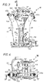
- a backlash mechanism due to the wear of the linings of the brake pads 12 and 14, marked 100, is provided at the ends upper arms and comprises the rod 40 provided at its ends with two threads with reverse steps as described above.
- the mechanism 100 also includes a wear detector which, when wear of the friction linings carried by the pads is detected, is placed in a so-called active position in which it is brought to train in rotation of the rod 40 around its axis in a so-called active direction which tends to bring one on the other, the pairs of arms 22, 23 on the one hand and 24, 25 on the other.
- a piece 102 in the form of substantially flat plate is arranged at the end 36a of the lever 36 in the direction of the rod 40 and comprises, in the zone in which this part is located look of said rod, a window 104 framing a pin 106 which is capable of move from one edge 104a of the window to the opposite edge 104b during a rotary movement of the lever 36 corresponding to the maximum stroke of the jack electrohydraulic 44, as well as the maximum opening stroke of the jaws of the brake.
- edges 104a and 104b of the window are not parallel to each other and the shape of the window is also slightly trapezoidal, the large base of the trapezium being turned towards the arms 24, 25 which will approach the window at as it wears.
- This arrangement of the opposite edges 104a, 104b of the window allows ensure consistency in catching up, depending on whether you are at the start wear or when the seals are considerably worn.
- the pin 106 is integral with a free wheel 108 coupled to the rod and, when the pin comes into contact with one of the aforementioned edges of the window 104, it causes freewheel rotation.
- the pin 106 moves between the two opposite edges 104a and 104b of the window which are spaced by a distance L corresponding to the stroke maximum jaw opening and maximum working stroke of displacement of the jack 44.
- the window 104 moves for each action by a distance which is equal to the distance L defined between the opposite edges 104a and 104b, lowering for the clamping action and rising for the brake release action.
- the maneuvering means constituted by the jack 44 compensate for the return force exerted by the elastic means 42 and cause the levers 36 to pivot and 37 in the direction indicated by the arrow 2 in FIG. 1, and therefore the ascent of the window 104.
- the wear detector remains in its inactive position.
- the freewheel is for example of the ratchet wheel type provided with a ratchet or of the combined freewheel type in which a ball bearing is combined with a freewheel with nylon cage cam, a ball alternating with a cam.
- the spout of the ratchet which was engaged between two teeth is then engaged between two other teeth, immediately consecutive or not, depending on the amount of rotation and therefore wear on the linings.
- the movement of the pin causes the rotational movement of the freewheel in the opposite direction which brings, for example, the beak of the pawl to the stop
- the rotational movement of the freewheel is then dependent on that of the rod 40 at an angle corresponding to the wear detected, thus allowing, thanks to the inverted threads of the rod, the approximation of the pairs of arms 22, 23 on the one hand and 24, 25 on the other hand and therefore corresponding jaws.
- the mass of the brake is distributed by so that when the jaws open, the articulated structure of the brake pivots to the right and weighs on the arms 22 and 23 which come into abutment thanks to the mechanism 110 which will be described later.
- a backlash mechanism allows for example to compensate for wear of the order of 0.03 mm in a single operation.
- the right / left screw system (rod 40 aux threads inverted at its ends) associated with the eccentric position of the window 104 allows to catch wear at least four to six times greater, without risk on reversibility.
- This arrangement does not affect the stability and reversibility of operation of the disc brake according to the invention.
- the mechanism 100 is more sensitive than in the centered position for an angle of given rotation of the levers.
- the mechanism of game take-up 100 functions reliably, this being, on the one hand, due to relatively large dimensions of window 104 and, on the other hand, bellows elements 84, 90 and 99 protecting the area of cooperation between the rod and the respective ends of the arms 24 and 25 and of the levers 36 and 37.
- Pawn 106 reaches a rest position which is lower than the position in which this pawn was before the clamping action and before wear detection.
- the disc brake according to the invention also includes a mechanism abutment 110 including a schematic sectional view along arrow VI of the Figure 3 is shown in Figure 6.
- This mechanism is mounted on the arms 22 and 23 which carry the jaw which happens to be the first to move away from the disc under the effect of gravity when the operating means constituted for example by the jack 44 are actuated to release the brake.
- the abutment mechanism includes a connecting member 112 extending perpendicular to the arms 22 and 23.
- the connecting member 112 connects the two arms 22 and 23 by two opposite end portions 114, 116 arranged along an axis called link 118 parallel to the pivot axis 30 of the arms.
- One of the end portions 114 has a body 115 of shape hollow cylindrical provided at its end 114a in contact with the portion opposite end 116 of a bore.
- the end portion 114 also has a head 117 perpendicular to the longitudinal direction of the cylindrical body 115 and which comes in support against the external face of the arm 22.
- a fixing system such as a screw 120 is provided to secure the head 117 from the end portion 114 to the arm 22.
- the end portion 114 crosses the arm 22 in its thickness and its cylindrical body 115 extends towards the other end portion opposite 116.
- This end portion 116 has a first cylindrical part 122 crossing the arm 23 in its thickness and which here protrudes from the internal face of this arm towards the cylindrical body 115 of the other portion end 114.
- the first cylindrical part 122 of the end portion 116 is extends by a second cylindrical portion of larger diameter 124 in direction of arm 22 and this second part has an internal housing cylindrical which in particular receives the end 114a of the end portion 114.
- the first part 122 of the end portion 116 is also digs and has a bore inside near the end 114a of the end portion 114.
- the link member 112 also includes a central portion 126 which is disposed between the second end portion 116 and the arm 22 and is crossed in its thickness by the body 115.
- friction means 128 constituted by example by a friction lining are interposed between the central portion 126 and the internal face of the arm 22.
- Elastic means 130 are arranged inside the housing defined by the second part 124 of the end portion 116 in order to exert a force compression on the central part 126 in order to maintain the means of friction 128 pressed against the internal face of the arm 22.
- a screw 132 is inserted inside the end portions 114 and 116 to join together.
- the connecting member 112 is coupled by means of a connecting rod link 134 fixed to the central portion 126 of said link member for example by a pin 136, to an element 138 mounted to pivot about a fixed axis 140 parallel to the axis of rotation 30 of the arms 22 and 23.
- This pivotally mounted element 138 here takes the form of a sleeve cylindrical perpendicular to the link 134 and coupled to it via two pins 142, 144.
- This sleeve 138 is fixedly held in its axial position between two ears 146 and 148 extending the two flanges 66 and 68 connected to the base 34.
- the sleeve 138 is mounted to rotate freely around the fixed axis 140 with a clearance J corresponding substantially to the distance d which represents half full opening of the two jaws, allowing arms 22 and 23 articulated around the axis 30 and to the assembly formed by the connecting member 112, the rod 134 and element 138, to move relative to the fixed axis 140 of the distance d.
- the jaw 18 then moves away from the corresponding face of the disc 20.
- the abutment mechanism 110 installed on the arms 22, 23 limits their travel so that the maximum opening of the jaw 16 carried by the corresponding arms is at most equal to the distance d.
- the other jaw 18 carried by arms 24 and 25 is also at a distance d from the disc, taking into account of the total opening of the jaws of the distance 2d controlled by the jack 44.
- the friction abutment mechanism 110 therefore makes it possible to control the distribution of the opening of the two jaws on either side of the disc.
- this mechanism 110 absorbs vibrations and shocks which can occur when the brake is released, thereby reducing wear and contact corrosion phenomena.
- This mechanism is also insensitive to conditions environment such as for example pollution and dust.
- the movements of the disc can be followed without excessive effort (veil, play, etc.), by controlled sliding of the arms 22 and 23 and redistribute the clearances between the linings and the disc after releasing the brake.
Landscapes
- Engineering & Computer Science (AREA)
- General Engineering & Computer Science (AREA)
- Mechanical Engineering (AREA)
- Braking Arrangements (AREA)
Abstract
Description
- deux patins destinés à coopérer avec les faces latérales d'un disque et portés par deux mâchoires,
- au moins deux bras en vis-à-vis portant chacun une mâchoire dans une partie distincte des deux extrémités opposées du bras considéré, les bras étant respectivement montés à rotation sur deux axes fixes à l'une O, O' de leurs extrémités disposées en vis-à-vis,
- au moins un levier monté à rotation sur l'extrémité opposée dite libre B de l'un des bras par une partie dudit levier distincte de ses deux extrémités opposées,
- une tige reliant le levier et l'autre bras,
- des moyens de manoeuvre aptes à entraíner en rotation le levier dans un sens ou dans un autre pour rapprocher ou écarter les mâchoires l'une de l'autre,
- un détecteur d'usure des patins porté par le levier et coopérant avec la tige.
- la figure 1 est une vue schématique d'un frein à disque selon l'invention ;
- la figure 2 est une vue en perspective montrant un exemple de réalisation d'un frein à disque selon l'invention ;
- la figure 3 est une vue suivant la flèche III du frein à disque de la figure 2;
- la figure 4 est une vue de dessus suivant la flèche IV du frein à disque de la figure 3 ;
- la figure 5 est une vue en coupe longitudinale suivant la flèche V de la figure 4 ;
- la figure 6 est une vue locale en coupe suivant la flèche VI de la figure 3.
Claims (15)
- Frein à disque comportantcaractérisé en ce que la tige (40) est pourvue de deux filets (80, 96) dont les pas sont inversés l'un par rapport à l'autre et qui coopèrent respectivement avec des éléments complémentaires (82,93) respectivement agencés à l'extrémité (D) du levier située à proximité de l'extrémité opposée dite libre (B) de l'un des bras, et à l'extrémité opposée dite libre (B') de l'autre bras, en sorte que, lorsque le levier (36) est placé dans une position dite active, il entraíne en rotation, dans un sens dit actif, la tige autour de son axe de manière à rapprocher les deux bras et donc les deux mâchoires l'une de l'autre.deux patins (12, 14) destinés à coopérer avec les faces latérales d'un disque (20) et portés par deux mâchoires (16, 18),au moins deux bras (22, 24) en vis-à-vis portant chacun une mâchoire dans une partie distincte des deux extrémités opposées du bras considéré, les bras étant respectivement montés à rotation sur deux axes fixes (30, 32) à l'une (O, O') de leurs extrémités disposées en vis-à-vis,au moins un levier (36) monté à rotation sur l'extrémité opposée dite libre (B) de l'un des bras (22) par une partie dudit levier distincte de ses deux extrémités opposées,une tige (40) reliant le levier (36) et l'autre bras (24),des moyens de manoeuvre (42, 44) aptes à entraíner en rotation le levier (36) dans un sens ou dans un autre pour rapprocher ou écarter les mâchoires (16, 18) l'une de l'autre,un détecteur d'usure (100) des patins porté par le levier (36) et coopérant avec la tige (40),
- Frein à disque selon la revendication 1 , caractérisé en ce que, dans sa position active, le détecteur d'usure entraíne en rotation une roue libre (108) attelée à la tige et qui provoque la rotation de cette dernière.
- Frein à disque selon la revendication 2, caractérisé en ce que, en dehors de la position active du détecteur d'usure, lorsque la roue libre (108) est entraínée en rotation par ledit détecteur d'usure, le mouvement de rotation de la roue libre est indépendant de celui de la tige.
- Frein à disque selon la revendication 2 ou 3, caractérisé en ce que, le détecteur d'usure (100) comporte un pion (106) solidaire de la roue libre et le levier (36) comporte, à son extrémité (D') opposée à l'extrémité (D) qui coopère avec la tige, une pièce (102) solidaire de cette extrémité opposée (D') et s'étendant en direction de la tige, une fenêtre (104) étant pratiquée dans ladite pièce pour recevoir le pion et permettre son déplacement à l'intérieur de ladite fenêtre, d'un bord (104a) de la fenêtre au bord opposé (104b), lors d'un mouvement de rotation du levier correspondant à l'ouverture maximale des mâchoires.
- Frein à disque selon la revendication 4, caractérisé en ce que, au delà d'un déplacement du pion correspondant à la course de fermeture maximale des mâchoires et donc au delà du mouvement de rotation correspondant de la roue libre (108), le détecteur d'usure (100) se trouve dans sa position active et le déplacement du pion (106), dans une direction correspondant au mouvement de rotation inverse du levier, entraíne en rotation la roue libre qui provoque à son tour la rotation de la tige (40).
- Frein à disque selon la revendication 4 ou 5, caractérisé en ce que les bords opposés (104a, 104b) de la fenêtre (104) ne sont pas parallèles entre eux afin d'assurer une constance dans le rattrapage du jeu dû à l'usure des patins, indépendamment du degré d'usure.
- Frein à disque selon l'une des revendications 1 à 6, caractérisé en ce que le détecteur d'usure (100) coopère avec une partie de la tige (40) située au voisinage d'une (40b) de ses extrémités qui est opposée à l'extrémité (40a) coopérant avec le levier (36).
- Frein à disque selon l'une des revendications 1 à 7, caractérisé en ce que chaque mâchoire (16, 18) est montée sur un bras par l'intermédiaire d'un axe dit de montage (26, 28) et une biellette (58, 60) est montée articulée par ses deux extrémités opposées autour de deux axes de pivotement (54, 62, 56, 64), l'un monté sur une queue (17, 19) de la mâchoire correspondante et l'autre monté sur un socle fixe (34), l'extrémité (O, O') dudit bras étant montée à rotation sur ledit socle par l'intermédiaire d'un axe de rotation (30, 32), l'ensemble des axes de montage, de pivotement et de rotation étant agencés parallèlement les uns aux autres et de manière à former un parallélogramme de commande.
- Frein à disque selon l'une des revendications 1 à 8, caractérisé en ce que, l'un des bras (22) portant la mâchoire (16) qui est la première à s'écarter du disque lorsque les moyens de manoeuvre (44) sont actionnés pour provoquer une action de défreinage est relié à un mécanisme de mise en butée (110) monté avec un jeu prédéterminé correspondant à la moitié de l'ouverture maximale des deux mâchoires, ledit mécanisme étant agencé et dimensionné pour permettre à ladite mâchoire de s'écarter du disque d'une distance d égale à la moitié de l'ouverture maximale des deux mâchoires lors d'un équilibrage dynamique du frein, répartissant ainsi également l'ouverture des mâchoires.
- Frein à disque selon la revendication 9, caractérisé en ce que le bras est doublé et le mécanisme de mise en butée (110) comporte un organe de liaison (112) entre les deux bras parallèles (22, 23) qui suit le mouvement de rotation des bras, ledit organe étant attelé à un élément (138) monté pivotant autour d'un axe fixe (140) qui est parallèle à l'axe de rotation des bras, l'élément pivotant (138) étant monté sur l'axe fixe avec un jeu correspondant à la distance d, de manière à ce que, lors du mouvement de rotation des bras, l'élément pivotant se déplace de la distance d et vient en butée contre ledit axe fixe.
- Frein à disque selon la revendication 10, caractérisé en ce que l'organe de liaison (112) relie les deux bras (22, 23) par deux portions d'extrémités (114, 116) opposées disposées le long d'un axe (118) dit de liaison parallèle à l'axe fixe de l'élément pivotant, ledit organe de liaison comportant une portion dite centrale (126) à laquelle est attelée une extrémité d'une biellette (134) reliée à l'élément pivotant (138) et des moyens de friction (128) étant agencés entre ladite portion centrale (126) et l'un des bras (22).
- Frein à disque selon la revendication 11, caractérisé en ce que l'une (114) des portions d'extrémité se prolonge à travers la portion centrale (126) en direction de l'autre portion d'extrémité (116) et les deux portions d'extrémité sont fixées l'une à l'autre.
- Frein à disque selon la revendication 12, caractérisé en ce que des moyens élastiques (130) sont agencés entre la portion d'extrémité (116) opposée à celle au voisinage de laquelle sont disposés les moyens de friction (128) et la portion centrale (126) de manière à maintenir lesdits moyens de friction serrés entre ladite portion centrale et le bras correspondant (22).
- Frein à disque selon l'une des revendications 1 à 13, caractérisé en ce qu'il comporte un limiteur d'effort en glissement d'au moins un des deux bras (22, 24) en vis-à-vis.
- Frein à disque selon les revendications 11 et 14, caractérisé en ce que le mécanisme de mise en butée (110) pourvu de moyens de friction maintenus serrés entre la portion centrale et le bras correspondant (22) est un limiteur d'effort.
Applications Claiming Priority (2)
| Application Number | Priority Date | Filing Date | Title |
|---|---|---|---|
| FR0108110A FR2826417B1 (fr) | 2001-06-20 | 2001-06-20 | Frein a disque notamment pour usage industriel |
| FR0108110 | 2001-06-20 |
Publications (2)
| Publication Number | Publication Date |
|---|---|
| EP1270980A1 true EP1270980A1 (fr) | 2003-01-02 |
| EP1270980B1 EP1270980B1 (fr) | 2007-06-13 |
Family
ID=8864551
Family Applications (1)
| Application Number | Title | Priority Date | Filing Date |
|---|---|---|---|
| EP02291509A Expired - Lifetime EP1270980B1 (fr) | 2001-06-20 | 2002-06-17 | Frein à disque notamment pour usage industriel |
Country Status (4)
| Country | Link |
|---|---|
| EP (1) | EP1270980B1 (fr) |
| DE (1) | DE60220589T2 (fr) |
| ES (1) | ES2287229T3 (fr) |
| FR (1) | FR2826417B1 (fr) |
Cited By (2)
| Publication number | Priority date | Publication date | Assignee | Title |
|---|---|---|---|---|
| EP3135946A1 (fr) * | 2015-08-24 | 2017-03-01 | Nabtesco Corporation | Dispositif d'étrier et dispositif de frein à disque le comprenant |
| JP2017044337A (ja) * | 2015-08-24 | 2017-03-02 | ナブテスコ株式会社 | キャリパ装置およびこの装置を備えるディスクブレーキ装置 |
Families Citing this family (1)
| Publication number | Priority date | Publication date | Assignee | Title |
|---|---|---|---|---|
| BR102020008271A2 (pt) * | 2020-04-24 | 2021-11-09 | Vulkan Do Brasil Ltda | Freio eletro-hidráulico a disco |
Citations (3)
| Publication number | Priority date | Publication date | Assignee | Title |
|---|---|---|---|---|
| US5660250A (en) * | 1993-02-20 | 1997-08-26 | Bubenzer Bremsen Gerhard Bubenzer Ing. Gmbh | Partially lined disc brake for installation in heavy-duty drives of industrial plants, ropeway drives, and cranes |
| EP0893615A2 (fr) | 1997-07-23 | 1999-01-27 | Nippon Ican Ltd. | Dispositif de frein à disque |
| EP0897071A2 (fr) * | 1997-08-13 | 1999-02-17 | Siegerland-Bremsen Emde Gmbh + Co. | Frein à disque |
-
2001
- 2001-06-20 FR FR0108110A patent/FR2826417B1/fr not_active Expired - Fee Related
-
2002
- 2002-06-17 ES ES02291509T patent/ES2287229T3/es not_active Expired - Lifetime
- 2002-06-17 EP EP02291509A patent/EP1270980B1/fr not_active Expired - Lifetime
- 2002-06-17 DE DE2002620589 patent/DE60220589T2/de not_active Expired - Lifetime
Patent Citations (3)
| Publication number | Priority date | Publication date | Assignee | Title |
|---|---|---|---|---|
| US5660250A (en) * | 1993-02-20 | 1997-08-26 | Bubenzer Bremsen Gerhard Bubenzer Ing. Gmbh | Partially lined disc brake for installation in heavy-duty drives of industrial plants, ropeway drives, and cranes |
| EP0893615A2 (fr) | 1997-07-23 | 1999-01-27 | Nippon Ican Ltd. | Dispositif de frein à disque |
| EP0897071A2 (fr) * | 1997-08-13 | 1999-02-17 | Siegerland-Bremsen Emde Gmbh + Co. | Frein à disque |
Cited By (6)
| Publication number | Priority date | Publication date | Assignee | Title |
|---|---|---|---|---|
| EP3135946A1 (fr) * | 2015-08-24 | 2017-03-01 | Nabtesco Corporation | Dispositif d'étrier et dispositif de frein à disque le comprenant |
| JP2017044337A (ja) * | 2015-08-24 | 2017-03-02 | ナブテスコ株式会社 | キャリパ装置およびこの装置を備えるディスクブレーキ装置 |
| CN106481696A (zh) * | 2015-08-24 | 2017-03-08 | 纳博特斯克有限公司 | 制动钳装置和具有该制动钳装置的盘式制动装置 |
| TWI621787B (zh) * | 2015-08-24 | 2018-04-21 | 納博特斯克股份有限公司 | 卡鉗裝置及具備該裝置之碟式刹車裝置 |
| CN106481696B (zh) * | 2015-08-24 | 2019-11-05 | 纳博特斯克有限公司 | 制动钳装置和具有该制动钳装置的盘式制动装置 |
| US11098775B2 (en) | 2015-08-24 | 2021-08-24 | Nabtesco Corporation | Caliper device and disc brake device including the same |
Also Published As
| Publication number | Publication date |
|---|---|
| ES2287229T3 (es) | 2007-12-16 |
| EP1270980B1 (fr) | 2007-06-13 |
| DE60220589T2 (de) | 2008-02-14 |
| FR2826417A1 (fr) | 2002-12-27 |
| DE60220589D1 (de) | 2007-07-26 |
| FR2826417B1 (fr) | 2003-10-10 |
Similar Documents
| Publication | Publication Date | Title |
|---|---|---|
| EP0080950B1 (fr) | Frein à disque à étrier monté coulissant | |
| EP2659149B1 (fr) | Dispositif de blocage entre deux tubes montes a coulissement | |
| EP0772749B1 (fr) | Patin et frein a disque l'utilisant | |
| EP0791144B1 (fr) | Dispositif d'actionnement mecanique pour frein a tambour | |
| EP0002632B1 (fr) | Dispositif de rattrapage d'usure pour frein et frein pourvu de ce dispositif | |
| EP0486341B1 (fr) | Frein à tambour à commande mécanique | |
| FR2548309A1 (fr) | Appareil d'accouplement tel que frein ou analogue dote d'un rattrapeur d'usure | |
| EP1270980B1 (fr) | Frein à disque notamment pour usage industriel | |
| EP0734496B1 (fr) | Entretoise de reglage automatique pour frein a tambour | |
| EP4003810B1 (fr) | Système de freinage ferroviaire comportant une timonerie de freinage et véhicule ferroviaire pourvu d'un tel système | |
| FR2548310A1 (fr) | Appareil d'accouplement tel que frein ou analogue avec un rattrapeur d'usure | |
| FR2918142A1 (fr) | Dispositif d'assistance a l'actionnement d'une pedale d'embrayage. | |
| EP0083881B1 (fr) | Frein à disque à étrier coulissant | |
| FR3045756A1 (fr) | Frein a disque electromecanique comportant un etrier portant deux plaquettes basculantes | |
| EP0186535B1 (fr) | Appareil d'accouplement par friction à rattrapage d'usure, tel que frein notamment | |
| FR2849136A1 (fr) | Moteur de frein a disque a rattrapage d'usure, et frein a disque equipe d'un tel moteur | |
| EP0524867B1 (fr) | Dispositif de freinage à mâchoires pour véhicules, notamment pour poids lourds | |
| EP0349368B1 (fr) | Frein à disque réglable | |
| FR2884893A1 (fr) | Bras articule pour support de distribution | |
| FR2463326A1 (fr) | Frein a disque a rattrapage automatique d'usure | |
| EP0094262A1 (fr) | Frein à rattrapage automatique d'usure | |
| FR3157328A1 (fr) | Système de freinage ferroviaire pour véhicule ferroviaire à freins à au moins une garniture ou à au moins une semelle | |
| EP1936225A1 (fr) | Dispositif de freinage | |
| LU84585A1 (fr) | Dispositif anti-lechage pour frein a couronne | |
| FR2646483A1 (fr) | Dispositif de freinage a disque comprenant des machoires articulees |
Legal Events
| Date | Code | Title | Description |
|---|---|---|---|
| PUAI | Public reference made under article 153(3) epc to a published international application that has entered the european phase |
Free format text: ORIGINAL CODE: 0009012 |
|
| AK | Designated contracting states |
Kind code of ref document: A1 Designated state(s): AT BE CH CY DE DK ES FI FR GB GR IE IT LI LU MC NL PT SE TR |
|
| AX | Request for extension of the european patent |
Free format text: AL;LT;LV;MK;RO;SI |
|
| 17P | Request for examination filed |
Effective date: 20030520 |
|
| AKX | Designation fees paid |
Designated state(s): DE ES FR IT |
|
| GRAP | Despatch of communication of intention to grant a patent |
Free format text: ORIGINAL CODE: EPIDOSNIGR1 |
|
| GRAS | Grant fee paid |
Free format text: ORIGINAL CODE: EPIDOSNIGR3 |
|
| GRAA | (expected) grant |
Free format text: ORIGINAL CODE: 0009210 |
|
| RIN1 | Information on inventor provided before grant (corrected) |
Inventor name: DUFOUR, GERARD Inventor name: LACRAMPE, JEROME Inventor name: EON, CHRISTIAN |
|
| AK | Designated contracting states |
Kind code of ref document: B1 Designated state(s): DE ES FR IT |
|
| REF | Corresponds to: |
Ref document number: 60220589 Country of ref document: DE Date of ref document: 20070726 Kind code of ref document: P |
|
| REG | Reference to a national code |
Ref country code: ES Ref legal event code: FG2A Ref document number: 2287229 Country of ref document: ES Kind code of ref document: T3 |
|
| PLBE | No opposition filed within time limit |
Free format text: ORIGINAL CODE: 0009261 |
|
| STAA | Information on the status of an ep patent application or granted ep patent |
Free format text: STATUS: NO OPPOSITION FILED WITHIN TIME LIMIT |
|
| 26N | No opposition filed |
Effective date: 20080314 |
|
| PGFP | Annual fee paid to national office [announced via postgrant information from national office to epo] |
Ref country code: IT Payment date: 20120626 Year of fee payment: 11 |
|
| PGFP | Annual fee paid to national office [announced via postgrant information from national office to epo] |
Ref country code: FR Payment date: 20120718 Year of fee payment: 11 Ref country code: ES Payment date: 20120518 Year of fee payment: 11 |
|
| PGFP | Annual fee paid to national office [announced via postgrant information from national office to epo] |
Ref country code: DE Payment date: 20121030 Year of fee payment: 11 |
|
| REG | Reference to a national code |
Ref country code: DE Ref legal event code: R119 Ref document number: 60220589 Country of ref document: DE Effective date: 20140101 |
|
| REG | Reference to a national code |
Ref country code: FR Ref legal event code: ST Effective date: 20140228 |
|
| PG25 | Lapsed in a contracting state [announced via postgrant information from national office to epo] |
Ref country code: DE Free format text: LAPSE BECAUSE OF NON-PAYMENT OF DUE FEES Effective date: 20140101 |
|
| PG25 | Lapsed in a contracting state [announced via postgrant information from national office to epo] |
Ref country code: IT Free format text: LAPSE BECAUSE OF NON-PAYMENT OF DUE FEES Effective date: 20130617 Ref country code: FR Free format text: LAPSE BECAUSE OF NON-PAYMENT OF DUE FEES Effective date: 20130701 |
|
| REG | Reference to a national code |
Ref country code: ES Ref legal event code: FD2A Effective date: 20140708 |
|
| PG25 | Lapsed in a contracting state [announced via postgrant information from national office to epo] |
Ref country code: ES Free format text: LAPSE BECAUSE OF NON-PAYMENT OF DUE FEES Effective date: 20130618 |