EP1270965A2 - Yoke, power transmission shaft, and method for manufacturing yoke - Google Patents
Yoke, power transmission shaft, and method for manufacturing yoke Download PDFInfo
- Publication number
- EP1270965A2 EP1270965A2 EP02013708A EP02013708A EP1270965A2 EP 1270965 A2 EP1270965 A2 EP 1270965A2 EP 02013708 A EP02013708 A EP 02013708A EP 02013708 A EP02013708 A EP 02013708A EP 1270965 A2 EP1270965 A2 EP 1270965A2
- Authority
- EP
- European Patent Office
- Prior art keywords
- yoke
- pipe
- serration
- teeth
- recesses
- Prior art date
- Legal status (The legal status is an assumption and is not a legal conclusion. Google has not performed a legal analysis and makes no representation as to the accuracy of the status listed.)
- Withdrawn
Links
- 230000005540 biological transmission Effects 0.000 title claims description 17
- 238000000034 method Methods 0.000 title claims description 16
- 238000004519 manufacturing process Methods 0.000 title claims description 10
- 238000010168 coupling process Methods 0.000 claims abstract description 45
- 230000008878 coupling Effects 0.000 claims abstract description 44
- 238000005859 coupling reaction Methods 0.000 claims abstract description 44
- 230000002093 peripheral effect Effects 0.000 claims abstract description 16
- 238000009751 slip forming Methods 0.000 claims abstract description 6
- 229920002430 Fibre-reinforced plastic Polymers 0.000 description 34
- 239000011151 fibre-reinforced plastic Substances 0.000 description 34
- 238000005520 cutting process Methods 0.000 description 14
- 229920005989 resin Polymers 0.000 description 11
- 239000011347 resin Substances 0.000 description 11
- 239000000428 dust Substances 0.000 description 7
- 230000003247 decreasing effect Effects 0.000 description 6
- 238000004804 winding Methods 0.000 description 6
- 230000007423 decrease Effects 0.000 description 5
- 239000000835 fiber Substances 0.000 description 5
- 239000011159 matrix material Substances 0.000 description 5
- 239000012783 reinforcing fiber Substances 0.000 description 5
- 238000005096 rolling process Methods 0.000 description 4
- 238000009730 filament winding Methods 0.000 description 3
- 229920000049 Carbon (fiber) Polymers 0.000 description 2
- 238000005452 bending Methods 0.000 description 2
- 239000004917 carbon fiber Substances 0.000 description 2
- 239000003822 epoxy resin Substances 0.000 description 2
- 238000005242 forging Methods 0.000 description 2
- 238000000227 grinding Methods 0.000 description 2
- 239000002184 metal Substances 0.000 description 2
- 229920000647 polyepoxide Polymers 0.000 description 2
- 229920001187 thermosetting polymer Polymers 0.000 description 2
- 239000013585 weight reducing agent Substances 0.000 description 2
- 244000025254 Cannabis sativa Species 0.000 description 1
- 230000003213 activating effect Effects 0.000 description 1
- 229920006231 aramid fiber Polymers 0.000 description 1
- 238000010273 cold forging Methods 0.000 description 1
- 230000000994 depressogenic effect Effects 0.000 description 1
- 239000000446 fuel Substances 0.000 description 1
- 238000003475 lamination Methods 0.000 description 1
- 239000000463 material Substances 0.000 description 1
- VNWKTOKETHGBQD-UHFFFAOYSA-N methane Chemical compound C VNWKTOKETHGBQD-UHFFFAOYSA-N 0.000 description 1
- 239000005011 phenolic resin Substances 0.000 description 1
- 229920001721 polyimide Polymers 0.000 description 1
- 239000009719 polyimide resin Substances 0.000 description 1
- 229920005992 thermoplastic resin Polymers 0.000 description 1
- 229920006337 unsaturated polyester resin Polymers 0.000 description 1
Images

Classifications
-
- F—MECHANICAL ENGINEERING; LIGHTING; HEATING; WEAPONS; BLASTING
- F16—ENGINEERING ELEMENTS AND UNITS; GENERAL MEASURES FOR PRODUCING AND MAINTAINING EFFECTIVE FUNCTIONING OF MACHINES OR INSTALLATIONS; THERMAL INSULATION IN GENERAL
- F16C—SHAFTS; FLEXIBLE SHAFTS; ELEMENTS OR CRANKSHAFT MECHANISMS; ROTARY BODIES OTHER THAN GEARING ELEMENTS; BEARINGS
- F16C3/00—Shafts; Axles; Cranks; Eccentrics
- F16C3/02—Shafts; Axles
- F16C3/026—Shafts made of fibre reinforced resin
-
- F—MECHANICAL ENGINEERING; LIGHTING; HEATING; WEAPONS; BLASTING
- F16—ENGINEERING ELEMENTS AND UNITS; GENERAL MEASURES FOR PRODUCING AND MAINTAINING EFFECTIVE FUNCTIONING OF MACHINES OR INSTALLATIONS; THERMAL INSULATION IN GENERAL
- F16D—COUPLINGS FOR TRANSMITTING ROTATION; CLUTCHES; BRAKES
- F16D1/00—Couplings for rigidly connecting two coaxial shafts or other movable machine elements
- F16D1/06—Couplings for rigidly connecting two coaxial shafts or other movable machine elements for attachment of a member on a shaft or on a shaft-end
- F16D1/064—Couplings for rigidly connecting two coaxial shafts or other movable machine elements for attachment of a member on a shaft or on a shaft-end non-disconnectable
- F16D1/072—Couplings for rigidly connecting two coaxial shafts or other movable machine elements for attachment of a member on a shaft or on a shaft-end non-disconnectable involving plastic deformation
-
- F—MECHANICAL ENGINEERING; LIGHTING; HEATING; WEAPONS; BLASTING
- F16—ENGINEERING ELEMENTS AND UNITS; GENERAL MEASURES FOR PRODUCING AND MAINTAINING EFFECTIVE FUNCTIONING OF MACHINES OR INSTALLATIONS; THERMAL INSULATION IN GENERAL
- F16D—COUPLINGS FOR TRANSMITTING ROTATION; CLUTCHES; BRAKES
- F16D3/00—Yielding couplings, i.e. with means permitting movement between the connected parts during the drive
- F16D3/16—Universal joints in which flexibility is produced by means of pivots or sliding or rolling connecting parts
- F16D3/26—Hooke's joints or other joints with an equivalent intermediate member to which each coupling part is pivotally or slidably connected
- F16D3/38—Hooke's joints or other joints with an equivalent intermediate member to which each coupling part is pivotally or slidably connected with a single intermediate member with trunnions or bearings arranged on two axes perpendicular to one another
- F16D3/382—Hooke's joints or other joints with an equivalent intermediate member to which each coupling part is pivotally or slidably connected with a single intermediate member with trunnions or bearings arranged on two axes perpendicular to one another constructional details of other than the intermediate member
- F16D3/387—Fork construction; Mounting of fork on shaft; Adapting shaft for mounting of fork
-
- F—MECHANICAL ENGINEERING; LIGHTING; HEATING; WEAPONS; BLASTING
- F16—ENGINEERING ELEMENTS AND UNITS; GENERAL MEASURES FOR PRODUCING AND MAINTAINING EFFECTIVE FUNCTIONING OF MACHINES OR INSTALLATIONS; THERMAL INSULATION IN GENERAL
- F16C—SHAFTS; FLEXIBLE SHAFTS; ELEMENTS OR CRANKSHAFT MECHANISMS; ROTARY BODIES OTHER THAN GEARING ELEMENTS; BEARINGS
- F16C2326/00—Articles relating to transporting
- F16C2326/01—Parts of vehicles in general
- F16C2326/06—Drive shafts
-
- F—MECHANICAL ENGINEERING; LIGHTING; HEATING; WEAPONS; BLASTING
- F16—ENGINEERING ELEMENTS AND UNITS; GENERAL MEASURES FOR PRODUCING AND MAINTAINING EFFECTIVE FUNCTIONING OF MACHINES OR INSTALLATIONS; THERMAL INSULATION IN GENERAL
- F16D—COUPLINGS FOR TRANSMITTING ROTATION; CLUTCHES; BRAKES
- F16D1/00—Couplings for rigidly connecting two coaxial shafts or other movable machine elements
- F16D1/10—Quick-acting couplings in which the parts are connected by simply bringing them together axially
- F16D2001/103—Quick-acting couplings in which the parts are connected by simply bringing them together axially the torque is transmitted via splined connections
Definitions
- the present invention relates to a yoke, a power transmission shaft used with the yoke, and a manufacturing method of the yoke. More specifically, the present invention pertains to a yoke used with a power transmission shaft, which has a pipe made of fiber-reinforced plastic (FRP) as the main body and is used, for example, as a vehicular propeller shaft, and to a method for manufacturing the yoke.
- FRP fiber-reinforced plastic
- FRP fiber-reinforced plastic
- main body main body
- yokes which form part of universal joint, or other parts (such as splined shaft) for transmitting drive force are secured to the ends of the propeller shaft.
- a pipe formed by a filament winding method is applied as the shaft portion made of FRP.
- the FRP pipe and the yoke are commonly secured by serrations (see Japanese Laid-Open Patent Publication No. 5-139170).
- a serration is formed on the peripheral surface of a portion of a yoke that is coupled to the FRP pipe.
- the outer diameter of the serration is larger than the inner diameter of the end portion of the FRP pipe.
- the coupling portion of the yoke is press-fitted into the FRP pipe.
- the teeth of the serration form grooves on the inner circumferential surface of the FRP pipe. The engagement of the teeth and the grooves provide coupling strength for the yoke and the pipe to be integrally rotated.
- Japanese Laid-Open Patent Publication No. 2000-120649 discloses a structure as shown in Figs. 4(a) and 4(b).
- a serration 42 is formed on the peripheral surface of a coupling portion 41a of a yoke 41.
- the serration 42 is separated into three annular portions in the axial direction.
- the coupling portion 41a of the yoke 41 is press-fitted into the inner surface of the end portion of a pipe 40 made of FRP.
- the serration 42 includes two annular portions 42b having no teeth 42a in the longitudinal direction. Thus, portions that have teeth 42a and portions that have no teeth 42a are alternately located in the pipe 40.
- the FRP pipe and the coupling portion of the yoke are required to maintain the transmission torque and minimize damage applied to the FRP pipe when press-fitting the yoke into the FRP pipe. Therefore, the force applied during press-fitting (press-fitting force) needs to be minimized.
- a propeller shaft that can be compressed in the axial direction or broken at a collision of a vehicle has been proposed for gently absorbing great impact generated at the collision.
- a yoke is further press-fitted into the pipe by the impact, thus compressing the propeller shaft in the axial direction or breaking the propeller shaft.
- the yoke is preferably press-fitted into the pipe with a small press-fitting force.
- the teeth of the serration extend in the axial direction in a uniform shape. This increases the frictional resistance generated when the teeth slide along the grooves, which are formed on the inner surface of the pipe. Also, the cutting dust of the FRP, which is generated when the grooves are formed, is caught between the teeth and the groove. This also increases the frictional resistance.
- the serration 42 includes portions that have teeth 42a and portions that have no teeth 42a in the longitudinal direction.
- the frictional resistance during press-fitting is small.
- the coupling portion needs to be elongated to maintain the required transmission torque. This increases the weight of the yoke.
- a second objective of the present invention is to provide a power transmission shaft that minimizes the force required to press-fit a yoke into a pipe made of FRP and that maintains a required transmission torque without elongating the portion that is coupled to the yoke.
- a third objective of the present invention is to provide a method for manufacturing a yoke with high productivity.
- the present invention provides a yoke secured to the inner surface of an FRP pipe.
- the yoke has first and second ends.
- the yoke includes a coupling portion located on the first end.
- the coupling portion has a peripheral surface and is secured to the inner surface of the pipe.
- a serration is formed on the peripheral surface of the coupling portion.
- the serration has teeth, which form grooves that extend axially along the inner surface of the pipe when the yoke is secured to the pipe.
- a plurality of recesses is formed on the vertex of each tooth in the longitudinal direction.
- the present invention also provides a power transmission shaft, which includes a FRP pipe and a pair of yokes.
- Each yoke is secured to one of the ends of the FRP pipe.
- Each yoke has a first end and a second end and includes a coupling portion located on the first end.
- the coupling portion has a peripheral surface and is secured to the inner surface of the pipe.
- a serration is formed on the peripheral surface of the coupling portion.
- the serration has teeth, which form grooves that extend axially along the inner surface of the pipe when the yoke is secured to the pipe.
- a plurality of recesses is continuously formed on the vertex of each tooth in the longitudinal direction.
- a further aspect of the present invention is a method for manufacturing a yoke having a coupling portion.
- a serration is formed on the peripheral surface of the coupling portion.
- the serration includes teeth, which form grooves that extend axially along the inner surface of an FRP pipe.
- the manufacturing method includes forming recesses at the vertex of each tooth in the longitudinal direction simultaneously with the teeth using a topping hob.
- a vehicular propeller shaft according to one embodiment of the present invention will now be described with reference to Figs. 1(a), 1(b), 1(c), 1(d), 2(a), and 2(b).
- a power transmission shaft which is the propeller shaft 1 in this embodiment, includes a pipe 2, which is made of FRP, and two metal yokes 3, each of which is secured to one of the ends of the pipe 2.
- Each yoke 3 has a coupling portion 3a.
- the pipe 2 has two joint sections 2a, each of which is located on one of the ends of the pipe 2.
- the coupling portion 3a of each yoke 3 is press-fitted in one of the joint sections 2a of the pipe 2 and secured by a serration.
- Each yoke 3 forms a part of a universal joint.
- the cross-sections of the pipe 2 and the coupling portion 3a of each yoke 3 are circular.
- the joint sections 2a of the pipe 2 are thick. Each joint section 2a has a tapered portion 2c. Each tapered portion 2c is thinnest on the side close to a main body 2b of the pipe 2 and gradually becomes thicker toward the corresponding end.
- the pipe 2 is made by filament winding method.
- the reinforcing fibers of the pipe 2 are carbon fibers.
- the matrix resin is epoxy resin. That is, a fiber bundle is wound about a mandrel (core) to form a pipe. The fiber-impregnated resin is then heated, which hardens the resin. After the resin is hardened, the mandrel is removed to form the pipe 2.
- the reinforcing fiber of the pipe 2 forms a fiber lamination, which includes helical layers and hoop layers.
- the helical layers are formed by winding the reinforcing fiber about the pipe 2 at a predetermined pitch such that the angle (winding angle) between the fiber and the axial direction of the pipe 2 is at a predetermined value.
- the winding angle of the hoop layers is substantially 90 degrees.
- the helical layers and the hoop layers are not distinguished in Figs. 1 and 2.
- the winding angle of the helical layers is set to a predetermined value, which is less than or equal to 45 degrees, to satisfy the characteristics required when the pipe 2 is installed in a vehicle.
- the examples of the above characteristics are the bending characteristics, the torsional characteristics, and the vibration characteristics.
- the winding angle is set to approximately plus or minus 10 degrees in the preferred embodiment to maintain the twist rigidity and the bending rigidity of the propeller shaft 1.
- the hoop layers are only formed at the joint sections 2a of the pipe 2 and arranged between the helical layers.
- the coupling portion 3a is formed on one end (first end) of the yoke 3, which is press-fitted in the pipe 2.
- the coupling portion 3a includes a serration 4 that has teeth 4a extending parallel to the axial direction of the yoke 3.
- a bore 3c is formed on the other side (second end) of the yoke 3 for attaching a universal joint (such as a cruciform joint).
- the teeth 4a of the serration 4 are formed at a predetermined pitch P1 in the circumferential direction.
- the cross-section of each tooth is substantially triangular.
- the vertex of each tooth 4a is chamfered to form an arc.
- a tapered portion 3b is formed on the distal end (right side as viewed in Fig. 1(a)) of the coupling portion 3a of the yoke 3.
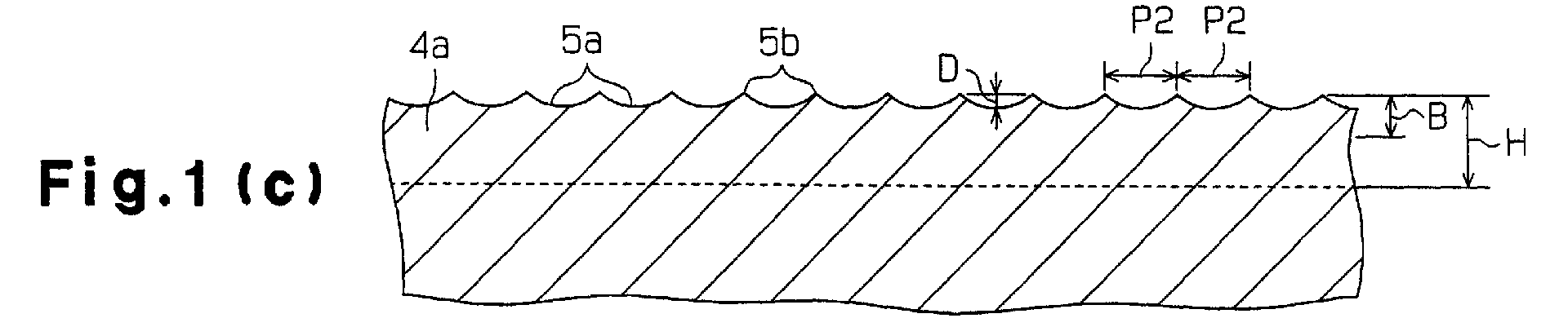
- Fig. 1(c) several recesses 5a are formed on the vertex of each tooth 4a in the longitudinal direction of the tooth 4a (the direction along the length of the tooth).
- projections 5b projecting portions formed by adjacent recesses 5a will be referred to as projections 5b.
- the recesses 5a and the projections 5b are shaped like saw-teeth.
- the depth of the recesses 5a is less than the dimension B of the part of the teeth 4a that cuts into the inner circumferential surface of the pipe 2.
- the height H (see Fig. 1(b) and 1(c)) of the teeth 4a is less than or equal to 1mm
- the depth D see Fig.
- the depth D of the recesses 5a is preferably 1 to 5% of the pitch P2 of the recesses 5a.
- the serration 4 of the yoke 3 is manufactured using a topping hob.
- the use of the topping hob allows processing the vertex, or the tip, of the teeth 4a.
- the tip of the teeth 4a can be made narrow.
- the topping hob can also cut the teeth 4a and process the recesses 5a in one procedure forming tooth tips, which are shaped like saw-teeth as shown in Fig. 1(c). That is, when processing the teeth 4a, the recesses 5a are simultaneously formed on the vertex of the teeth.
- each tooth 4a includes the recesses 5a and the projections 5b, which are alternately and continuously arranged on the vertex.
- the diameter of the topping hob is decreased.
- the depth of the recesses 5a is increased by increasing the feed pitch of the hob.
- the depth of the recesses 5a can be adjusted in a range between 0.01 to 0.1mm by changing the feed pitch of the hob a range between approximately 1 to 5mm.
- the press-fitting force is the sum of the force required for the tips of the serration to form the serration grooves 6 cutting into the inner surface of the pipe 2 and the frictional force between the serration grooves 6 and the teeth 4a.
- the contact area between the serration grooves 6 and the teeth 4a is large.
- the recesses 5a and the projections 5b are formed on the vertex of each tooth 4a. Therefore, the contact area between the serration grooves 6 and the teeth 4a is decreased compared with the above case.
- the frictional force between the serration groves 6 and the teeth 4a decreases, which then decreases the press-fitting force.
- the recesses 5a and the projections 5b are formed on the vertex of the teeth 4a. Therefore, when press fitting each yoke 3, one of the projections 5b located at the front side in the press-fitting direction cuts the inner surface of the pipe 2. Then, the projection 5b passes the cut portion and the following recess 5a passes the cut portion. After the recess 5a has passed the cut portion, the next projection 5b passes the cut portion cutting the cut portion again. That is, the teeth 4a of the serration 4 cut the inner surface of the pipe 2 little by little while proceeding so that the depth of the serration grooves increases. Thus, the squeezing force of the pipe 2 with respect to the serration 4 decreases, which decreases the frictional force.
- each serration 4 is greater than the inner diameter of the pipe 2.
- the teeth 4a easily widen the inner circumferential surface of the pipe 2. Therefore, the pipe 2 is easily damaged during press-fitting.
- the serration 4 is press-fitted with a small press-fitting force, the serration grooves 6 are formed while preventing the pipe 2 from being damaged.
- the teeth 4a of the serration 4 of each yoke 3 is firmly engaged with the corresponding serration grooves 6.
- One yoke 3 is secured to each end of the pipe 2 to form the propeller shaft 1.
- the first embodiment provides the following advantages.
- the teeth 4a of the serration 4 and the recesses 5a are processed in one procedure, which improves the productivity. Compared with a case, when processing narrow teeth tips without using the topping hob, the narrow teeth tips can be formed without requiring high accuracy.
- recesses 5a the cross-sections of which describe arcs, may be formed on the vertex of each tooth 4a at predetermined intervals such that a flat portion 4b axially extends between each recess 5a.
- recesses 5a the cross-sections of which are rectangular, may be formed on the vertex of each tooth 4a at predetermined intervals such that a flat portion 4b axially extends between each recess 5a.
- the teeth 4a and the recesses 5a cannot be formed in one procedure using the topping hob for the above described shapes. Therefore, annular grooves, which extend in the circumferential direction, may be formed on the peripheral surface of the coupling portion 3a with a lathe first. Then, the teeth 4a are processed with a hob to form the serration 4. The teeth 4a may be formed with the hob first and the recesses 5a may then be processed with a lathe.
- the further embodiment provides the same advantages as described in (1), (3), and (4) of the preferred embodiment. Compared with the preferred embodiment, the contact area between the serration grooves 6 and the teeth 4a increases, thus improving the torque transmission efficiency. This adds to the flexibility of the design of the recesses 5a.
- the topping hob is used for processing the recesses 5a and the projections 5b on the vertex of each tooth 4a of the serration 4.
- the recesses and the projections which extend in the circumferential direction on the peripheral surface of the coupling portion 3a of each yoke 3, may be formed by cutting and rolling.
- the serration 4 may be formed by cutting, grinding, or rolling using, for example, a hob, a gear shaper, or angular cutter. This adds to the flexibility of the design of the recesses 5a.
- the recesses 5a having the depth of 0.01 to 0.1mm may be formed during surface finish before processing the serration. Then, the serration 4 may be formed.
- the recesses 5a may be formed on the vertex of each tooth 4a by cutting or rolling. This also adds flexibility to the design of the recesses 5a.
- the shape of the recesses 5a is not limited to rectangular or arcuate but may be triangular, trapezoidal, or other shapes.
- the cross-sectional shape of the FRP pipe need not be circular but may be triangular, rectangular or polygonal.
- the method for manufacturing the FRP pipe is not limited to the filament winding method.
- a sheet winding method may be applied.
- the manufacturing method is not limited as long as the FRP pipe is manufactured such that the characteristics required for using as a drive shaft is satisfied.
- each yoke 3 is cylindrical in the preferred embodiment.
- the coupling portion 3a need not be cylindrical.
- the coupling portion 3a may be columnar.
- the coupling portion 3a is preferably cylindrical in view of weight reduction and the strength.
- the power transmission shaft is not limited to the propeller shaft 1.
- the present invention may be applied to other power transmission shafts.
- the coupling method according to the above embodiments may be applied.
- the material of the pipe 2 is not limited to the FRP that uses carbon fiber as the reinforcing fiber and the epoxy resin as the matrix resin.
- other fibers that are generally regarded as having high elasticity and high strength such as aramid fiber and grass fiber, may be applied as the reinforcing fiber and other thermosetting resin, such as unsaturated polyester resin, phenol resin, or polyimide resin, may be applied as the matrix resin.
- the matrix resin of the FRP need not be thermosetting resin.
- ultraviolet curing resin or thermoplastic resin may be used as the matrix resin.
- the tapered portion 2c includes one that the diameter changes continuously or the diameter increases stepwise toward the end of the pipe 2.
- a yoke (3) is secured to the inner surface of an FRP pipe (2).
- the yoke (3) has a first end and a coupling portion (3a) is located on the first end.
- the coupling portion (3a) has a peripheral surface and is secured to the inner surface of the pipe (2).
- a serration (4) is formed on the peripheral surface of the coupling portion (3a).
- the serration (4) has teeth (4a) that can form grooves, which axially extend along the inner surface of the pipe (2) when securing the yoke (3) to the pipe (2).
- Recesses (5a) are continuously formed on the vertex of each tooth (4a) in the longitudinal direction.
Landscapes
- Engineering & Computer Science (AREA)
- General Engineering & Computer Science (AREA)
- Mechanical Engineering (AREA)
- Ocean & Marine Engineering (AREA)
- Shafts, Cranks, Connecting Bars, And Related Bearings (AREA)
- Motor Power Transmission Devices (AREA)
Abstract
Description
- The present invention relates to a yoke, a power transmission shaft used with the yoke, and a manufacturing method of the yoke. More specifically, the present invention pertains to a yoke used with a power transmission shaft, which has a pipe made of fiber-reinforced plastic (FRP) as the main body and is used, for example, as a vehicular propeller shaft, and to a method for manufacturing the yoke.
- Weight reduction of vehicle parts has been pursued to improve fuel economy of automobiles. For example, fiber-reinforced plastic (FRP) is used instead of metal for shafts such as a propeller shaft. In a case with propeller shafts, FRP has been applied for forming the shaft portion (main body). In this case, yokes, which form part of universal joint, or other parts (such as splined shaft) for transmitting drive force are secured to the ends of the propeller shaft. A pipe formed by a filament winding method is applied as the shaft portion made of FRP.
- The FRP pipe and the yoke are commonly secured by serrations (see Japanese Laid-Open Patent Publication No. 5-139170).
- A serration is formed on the peripheral surface of a portion of a yoke that is coupled to the FRP pipe. The outer diameter of the serration is larger than the inner diameter of the end portion of the FRP pipe. The coupling portion of the yoke is press-fitted into the FRP pipe. Thus, the teeth of the serration form grooves on the inner circumferential surface of the FRP pipe. The engagement of the teeth and the grooves provide coupling strength for the yoke and the pipe to be integrally rotated.
- Japanese Laid-Open Patent Publication No. 2000-120649 discloses a structure as shown in Figs. 4(a) and 4(b). According to the above publication, a
serration 42 is formed on the peripheral surface of acoupling portion 41a of ayoke 41. Theserration 42 is separated into three annular portions in the axial direction. Thecoupling portion 41a of theyoke 41 is press-fitted into the inner surface of the end portion of apipe 40 made of FRP. Theserration 42 includes twoannular portions 42b having noteeth 42a in the longitudinal direction. Thus, portions that haveteeth 42a and portions that have noteeth 42a are alternately located in thepipe 40. - The FRP pipe and the coupling portion of the yoke are required to maintain the transmission torque and minimize damage applied to the FRP pipe when press-fitting the yoke into the FRP pipe. Therefore, the force applied during press-fitting (press-fitting force) needs to be minimized.
- To allow time for activating safety devices such as an air bag, a propeller shaft that can be compressed in the axial direction or broken at a collision of a vehicle has been proposed for gently absorbing great impact generated at the collision. According to this art, when the impact applied to the propeller shaft in the axial direction exceeds a predetermined level, a yoke is further press-fitted into the pipe by the impact, thus compressing the propeller shaft in the axial direction or breaking the propeller shaft. In this case also, the yoke is preferably press-fitted into the pipe with a small press-fitting force.
- However, the teeth of the serration extend in the axial direction in a uniform shape. This increases the frictional resistance generated when the teeth slide along the grooves, which are formed on the inner surface of the pipe. Also, the cutting dust of the FRP, which is generated when the grooves are formed, is caught between the teeth and the groove. This also increases the frictional resistance.
- According to the structure disclosed in the Publication No. 2000-120649, the
serration 42 includes portions that haveteeth 42a and portions that have noteeth 42a in the longitudinal direction. Thus, the frictional resistance during press-fitting is small. However, since there are portions that have noteeth 42a, the coupling portion needs to be elongated to maintain the required transmission torque. This increases the weight of the yoke. - Accordingly, it is a first objective of the present invention to provide a yoke that minimizes the press-fitting force required to secure the yoke to a pipe made of FRP with a serration while forming grooves in the pipe and that maintains a required transmission torque without elongating the coupling portion.
- A second objective of the present invention is to provide a power transmission shaft that minimizes the force required to press-fit a yoke into a pipe made of FRP and that maintains a required transmission torque without elongating the portion that is coupled to the yoke.
- A third objective of the present invention is to provide a method for manufacturing a yoke with high productivity.
- To achieve the above objectives, the present invention provides a yoke secured to the inner surface of an FRP pipe. The yoke has first and second ends. The yoke includes a coupling portion located on the first end. The coupling portion has a peripheral surface and is secured to the inner surface of the pipe. A serration is formed on the peripheral surface of the coupling portion. The serration has teeth, which form grooves that extend axially along the inner surface of the pipe when the yoke is secured to the pipe. A plurality of recesses is formed on the vertex of each tooth in the longitudinal direction.
- The present invention also provides a power transmission shaft, which includes a FRP pipe and a pair of yokes. Each yoke is secured to one of the ends of the FRP pipe. Each yoke has a first end and a second end and includes a coupling portion located on the first end. The coupling portion has a peripheral surface and is secured to the inner surface of the pipe. A serration is formed on the peripheral surface of the coupling portion. The serration has teeth, which form grooves that extend axially along the inner surface of the pipe when the yoke is secured to the pipe. A plurality of recesses is continuously formed on the vertex of each tooth in the longitudinal direction.
- A further aspect of the present invention is a method for manufacturing a yoke having a coupling portion. A serration is formed on the peripheral surface of the coupling portion. The serration includes teeth, which form grooves that extend axially along the inner surface of an FRP pipe. The manufacturing method includes forming recesses at the vertex of each tooth in the longitudinal direction simultaneously with the teeth using a topping hob.
- Other aspects and advantages of the invention will become apparent from the following description, taken in conjunction with the accompanying drawings, illustrating by way of example the principles of the invention.
- The invention, together with objects and advantages thereof, may best be understood by reference to the following description of the presently preferred embodiments together with the accompanying drawings in which:
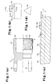
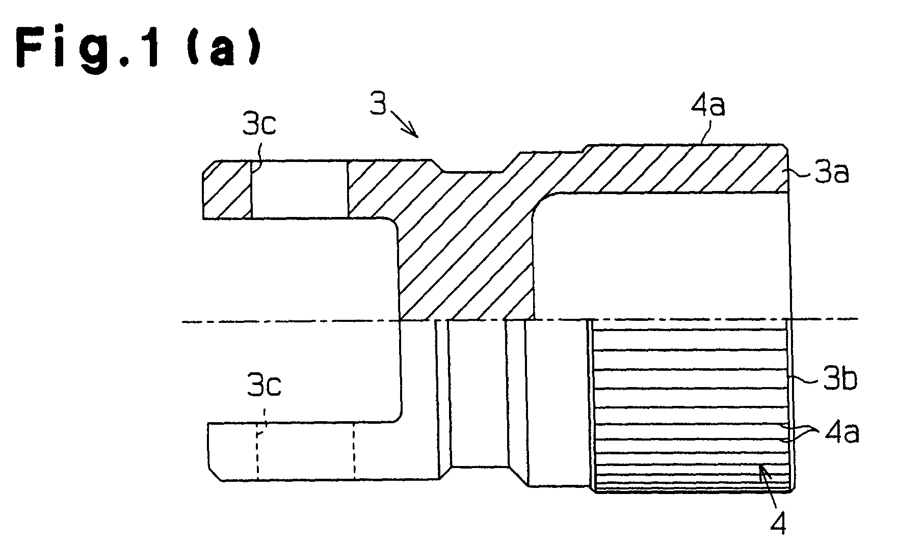
- Fig. 1(a) is a side view, with a part cut away, illustrating a yoke according to a first embodiment of the present invention;
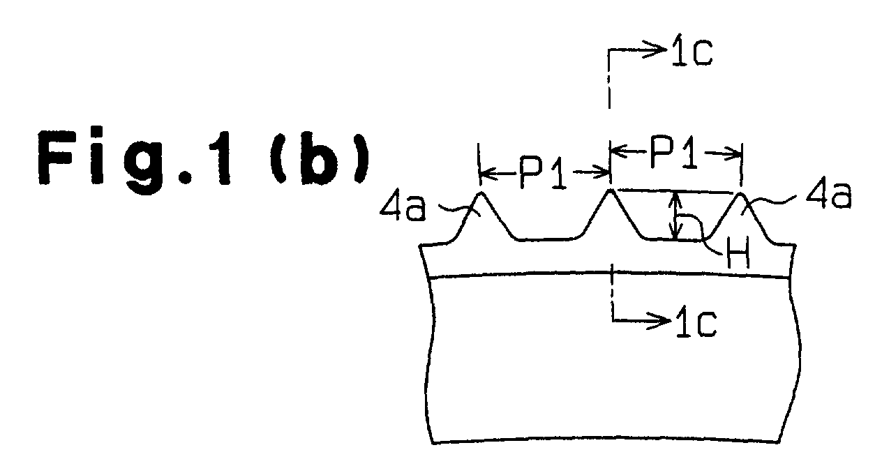
- Fig. 1(b) is an enlarged partial front view illustrating the yoke shown in Fig. 1(a).
- Fig. 1(c) is a cross-sectional view taken along line 1c-1c in Fig. 1(b) illustrating teeth of a serration;
- Fig. 1(d) is an enlarged partial view illustrating the yoke shown in Fig. 1(b);
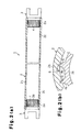
- Fig. 2(a) is a diagrammatic cross-sectional view illustrating a propeller shaft;
- Fig. 2(b) is an enlarged partial cross-sectional view illustrating a coupling portion of the serration and a pipe;
- Figs. 3(a) and 3(b) are enlarged cross-sectional views illustrating a yoke according to further embodiments of the present invention;
- Fig. 4(a) is a side view, with a part cut away, illustrating the relationship between a pipe and a yoke according to a prior art; and
- Fig. 4(b) is a partial cross-sectional view illustrating a coupling portion of the yoke shown in Fig. 4(a).
-
- A vehicular propeller shaft according to one embodiment of the present invention will now be described with reference to Figs. 1(a), 1(b), 1(c), 1(d), 2(a), and 2(b).
- As shown in Fig. 2(a), a power transmission shaft, which is the propeller shaft 1 in this embodiment, includes a
pipe 2, which is made of FRP, and twometal yokes 3, each of which is secured to one of the ends of thepipe 2. Eachyoke 3 has acoupling portion 3a. Thepipe 2 has twojoint sections 2a, each of which is located on one of the ends of thepipe 2. Thecoupling portion 3a of eachyoke 3 is press-fitted in one of thejoint sections 2a of thepipe 2 and secured by a serration. Eachyoke 3 forms a part of a universal joint. The cross-sections of thepipe 2 and thecoupling portion 3a of eachyoke 3 are circular. - The
joint sections 2a of thepipe 2 are thick. Eachjoint section 2a has a taperedportion 2c. Each taperedportion 2c is thinnest on the side close to amain body 2b of thepipe 2 and gradually becomes thicker toward the corresponding end. Thepipe 2 is made by filament winding method. The reinforcing fibers of thepipe 2 are carbon fibers. The matrix resin is epoxy resin. That is, a fiber bundle is wound about a mandrel (core) to form a pipe. The fiber-impregnated resin is then heated, which hardens the resin. After the resin is hardened, the mandrel is removed to form thepipe 2. - The reinforcing fiber of the
pipe 2 forms a fiber lamination, which includes helical layers and hoop layers. The helical layers are formed by winding the reinforcing fiber about thepipe 2 at a predetermined pitch such that the angle (winding angle) between the fiber and the axial direction of thepipe 2 is at a predetermined value. The winding angle of the hoop layers is substantially 90 degrees. The helical layers and the hoop layers are not distinguished in Figs. 1 and 2. - The winding angle of the helical layers is set to a predetermined value, which is less than or equal to 45 degrees, to satisfy the characteristics required when the
pipe 2 is installed in a vehicle. The examples of the above characteristics are the bending characteristics, the torsional characteristics, and the vibration characteristics. The winding angle is set to approximately plus or minus 10 degrees in the preferred embodiment to maintain the twist rigidity and the bending rigidity of the propeller shaft 1. The hoop layers are only formed at thejoint sections 2a of thepipe 2 and arranged between the helical layers. - Since the
yokes 3 are identical, the structure of one of theyokes 3 will be described. Thecoupling portion 3a is formed on one end (first end) of theyoke 3, which is press-fitted in thepipe 2. Thecoupling portion 3a includes aserration 4 that hasteeth 4a extending parallel to the axial direction of theyoke 3. Abore 3c is formed on the other side (second end) of theyoke 3 for attaching a universal joint (such as a cruciform joint). - As shown in Figs. 1(b) and 2(b), the
teeth 4a of theserration 4 are formed at a predetermined pitch P1 in the circumferential direction. The cross-section of each tooth is substantially triangular. As shown in Fig. 1(d), the vertex of eachtooth 4a is chamfered to form an arc. A taperedportion 3b is formed on the distal end (right side as viewed in Fig. 1(a)) of thecoupling portion 3a of theyoke 3. - As shown in Fig. 1(c),
several recesses 5a are formed on the vertex of eachtooth 4a in the longitudinal direction of thetooth 4a (the direction along the length of the tooth). For purposes of explanation, projecting portions formed byadjacent recesses 5a will be referred to asprojections 5b. In the preferred embodiment, therecesses 5a and theprojections 5b are shaped like saw-teeth. The depth of therecesses 5a is less than the dimension B of the part of theteeth 4a that cuts into the inner circumferential surface of thepipe 2. For example, the height H (see Fig. 1(b) and 1(c)) of theteeth 4a is less than or equal to 1mm, the depth D (see Fig. 1(c)) of therecesses 5a is approximately 0.01 to 0.1mm, the dimension B of the part of theteeth 4a that cuts into the inner circumferential surface is 0.05 to 0.5mm, and the pitch P2 (see Fig. 1(c)) of therecesses 5a and theprojections 5b are approximately 1 to 5mm. The depth D of therecesses 5a is preferably 1 to 5% of the pitch P2 of therecesses 5a. - The
serration 4 of theyoke 3 is manufactured using a topping hob. Compared to a case when a standard hob is used, the use of the topping hob allows processing the vertex, or the tip, of theteeth 4a. Furthermore, the tip of theteeth 4a can be made narrow. The topping hob can also cut theteeth 4a and process therecesses 5a in one procedure forming tooth tips, which are shaped like saw-teeth as shown in Fig. 1(c). That is, when processing theteeth 4a, therecesses 5a are simultaneously formed on the vertex of the teeth. Thus, eachtooth 4a includes therecesses 5a and theprojections 5b, which are alternately and continuously arranged on the vertex. To increase the number of recesses and projections, the diameter of the topping hob is decreased. When using the topping hob with the same diameter, the depth of therecesses 5a is increased by increasing the feed pitch of the hob. The depth of therecesses 5a can be adjusted in a range between 0.01 to 0.1mm by changing the feed pitch of the hob a range between approximately 1 to 5mm. - A method for securing the
yokes 3 to theFRP pipe 2 will now be described. To secure theyokes 3 to thepipe 2 as shown in Fig. 2(a), thepipe 2 is fixed with a jig and the axis of eachyoke 3 is aligned with the axis of thepipe 2. Then, theserration 4 of eachyoke 3 is press-fitted in one of the ends of thepipe 2 with a tool. As eachserration 4 is press-fitted, the correspondingteeth 4a form serration grooves 6 (see Fig. 2(b)) on the inner circumferential surface of thepipe 2 extending in the axial direction. - The press-fitting force is the sum of the force required for the tips of the serration to form the
serration grooves 6 cutting into the inner surface of thepipe 2 and the frictional force between theserration grooves 6 and theteeth 4a. In a case when theteeth 4a are axially formed in a uniform shape, the contact area between theserration grooves 6 and theteeth 4a is large. However, therecesses 5a and theprojections 5b are formed on the vertex of eachtooth 4a. Therefore, the contact area between theserration grooves 6 and theteeth 4a is decreased compared with the above case. As a result, the frictional force between theserration groves 6 and theteeth 4a decreases, which then decreases the press-fitting force. - When the
serration grooves 6 are formed in theFRP pipe 2, cutting dust is generated. The frictional resistance increases if the FRP cutting dust enters between theteeth 4a and the wall of theserration grooves 6. However, therecesses 5a and theprojections 5b are continuously formed on the vertex of eachtooth 4a in the longitudinal direction. Therefore, when theserration 4 is press-fitted in theFRP pipe 2 formingserration grooves 6, the cutting dust is accommodated in therecesses 5a. Therefore, the cutting dust does not easily enter the space between the wall of theserration grooves 6 and theteeth 4a, thus reducing the frictional resistance. As a result, the press-fitting force required to press-fit theyokes 3 in thepipe 2 decreases. - The
recesses 5a and theprojections 5b are formed on the vertex of theteeth 4a. Therefore, when press fitting eachyoke 3, one of theprojections 5b located at the front side in the press-fitting direction cuts the inner surface of thepipe 2. Then, theprojection 5b passes the cut portion and thefollowing recess 5a passes the cut portion. After therecess 5a has passed the cut portion, thenext projection 5b passes the cut portion cutting the cut portion again. That is, theteeth 4a of theserration 4 cut the inner surface of thepipe 2 little by little while proceeding so that the depth of the serration grooves increases. Thus, the squeezing force of thepipe 2 with respect to theserration 4 decreases, which decreases the frictional force. - The outer diameter of each
serration 4 is greater than the inner diameter of thepipe 2. When the press-fitting force is great, theteeth 4a easily widen the inner circumferential surface of thepipe 2. Therefore, thepipe 2 is easily damaged during press-fitting. However, since theserration 4 is press-fitted with a small press-fitting force, theserration grooves 6 are formed while preventing thepipe 2 from being damaged. Further, theteeth 4a of theserration 4 of eachyoke 3 is firmly engaged with the correspondingserration grooves 6. Thus, thepipe 2 and eachyoke 3 are secured with great strength. Oneyoke 3 is secured to each end of thepipe 2 to form the propeller shaft 1. - The first embodiment provides the following advantages.
- (1) The
coupling portion 3a is located on one end of eachyoke 3. Theserration 4, which hasteeth 4a, is formed on the outer circumferential surface of eachcoupling portion 3a. Theteeth 4a can form grooves in the inner surface of thepipe 2 in the axial direction of thepipe 2. Therecesses 5a and theprojections 5b are continuously formed on the vertex of eachtooth 4a in the longitudinal direction. Therefore, when eachserration 4 is press-fitted in thepipe 2 while formingserration grooves 6, the frictional resistance between theserration grooves 6 and theteeth 4a is decreased. Also, since the cutting dust is accommodated in therecesses 5a, the cutting dust does not easily enter the space between the wall of theserration grooves 6 and theteeth 4a. This reduces the frictional resistance. As a result, the press-fitting force required to press-fit eachyoke 3 in thepipe 2 is decreased. This facilitates the assembling procedure of theyokes 3. - (2) Since the
recesses 5a and theprojections 5b are shaped like saw-teeth, the tips of theprojections 5b are sharp. This facilitates cutting of theserration grooves 6 in thepipe 2. As a result, the press-fitting force required to press-fit eachyoke 3 is decreased, which facilitates the assembling of theyokes 3 to thepipe 2. - (3) The propeller shaft 1 is formed by press fitting
each
yoke 3, which is formed as above, to the circumferential surface of one of the end portions of theFRP pipe 2. Therefore, eachyoke 3 can be press-fitted with a small press-fitting force. This suppresses damage on thepipe 2 caused during assembling. As a result, theteeth 4a of eachserration 4 are firmly engaged with the inner circumferential surface of thepipe 2. This provides great coupling strength between thepipe 2 and eachyoke 3. Also, the present invention differs from the case when the teeth of the serration is separated in the longitudinal direction providing portions having no teeth, in that theteeth 4a of eachserration 4 contact the entire length of theserration grooves 6, which are formed in the inner circumferential surface of thepipe 2. Therefore, the required transmission torque is obtained without elongating eachserration 4. When an axial load is applied on theyokes 3 to compress the yokes at the collision of the vehicle, theyokes 3 are depressed into thepipe 2 with a small force. Thus, the propeller shaft 1 is smoothly compressed or broken in the axial direction. - (4) The depth of the
recesses 5a is less than the dimension of the portion that cuts into the inner circumferential surface of the end portion of thepipe 2. Therefore, compared to a case when the depth of therecesses 5a is greater than the dimension of the portion that cuts into the inner circumferential surface of the end portion of thepipe 2, the contact area between theteeth 4a and the wall of thegrooves 6 is increased. Thus, the length of the serration needed for maintaining the required transmission torque is decreased. - (5) The
serration 4 of eachyoke 3 is processed using the topping hob. Theteeth 4a and therecesses 5a, which are formed on the vertex of eachtooth 4a, are simultaneously processed to continuously form therecesses 5a and theprojections 5b on the vertex of eachtooth 4a in the longitudinal direction. -
- Therefore, the
teeth 4a of theserration 4 and therecesses 5a are processed in one procedure, which improves the productivity. Compared with a case, when processing narrow teeth tips without using the topping hob, the narrow teeth tips can be formed without requiring high accuracy. - It should be apparent to those skilled in the art that the present invention may be embodied in many other specific forms without departing from the spirit or scope of the invention. Particularly, it should be understood that the invention may be embodied in the following forms.
- The
recesses 5a and theprojections 5b, which are formed on the vertex of eachtooth 4a, need not be shaped like saw-teeth. For example, as shown in Fig. 3(a), recesses 5a, the cross-sections of which describe arcs, may be formed on the vertex of eachtooth 4a at predetermined intervals such that aflat portion 4b axially extends between eachrecess 5a. As shown in Fig. 3(b), recesses 5a, the cross-sections of which are rectangular, may be formed on the vertex of eachtooth 4a at predetermined intervals such that aflat portion 4b axially extends between eachrecess 5a. - The
teeth 4a and therecesses 5a cannot be formed in one procedure using the topping hob for the above described shapes. Therefore, annular grooves, which extend in the circumferential direction, may be formed on the peripheral surface of thecoupling portion 3a with a lathe first. Then, theteeth 4a are processed with a hob to form theserration 4. Theteeth 4a may be formed with the hob first and therecesses 5a may then be processed with a lathe. The further embodiment provides the same advantages as described in (1), (3), and (4) of the preferred embodiment. Compared with the preferred embodiment, the contact area between theserration grooves 6 and theteeth 4a increases, thus improving the torque transmission efficiency. This adds to the flexibility of the design of therecesses 5a. - In the preferred embodiment, the topping hob is used for processing the
recesses 5a and theprojections 5b on the vertex of eachtooth 4a of theserration 4. However, the recesses and the projections, which extend in the circumferential direction on the peripheral surface of thecoupling portion 3a of eachyoke 3, may be formed by cutting and rolling. After the recesses and the projections are formed, theserration 4 may be formed by cutting, grinding, or rolling using, for example, a hob, a gear shaper, or angular cutter. This adds to the flexibility of the design of therecesses 5a. - The
recesses 5a having the depth of 0.01 to 0.1mm may be formed during surface finish before processing the serration. Then, theserration 4 may be formed. - After forming the serration by cutting and grinding using a hob, gear shaper, angle cutter, or the like, or rolling, forging (cold forging, hot forging), drawing, or the like, the
recesses 5a may be formed on the vertex of eachtooth 4a by cutting or rolling. This also adds flexibility to the design of therecesses 5a. - The shape of the
recesses 5a is not limited to rectangular or arcuate but may be triangular, trapezoidal, or other shapes. - The cross-sectional shape of the FRP pipe need not be circular but may be triangular, rectangular or polygonal.
- The method for manufacturing the FRP pipe is not limited to the filament winding method. For example, a sheet winding method may be applied. The manufacturing method is not limited as long as the FRP pipe is manufactured such that the characteristics required for using as a drive shaft is satisfied.
- The
coupling portion 3a of eachyoke 3 is cylindrical in the preferred embodiment. However, thecoupling portion 3a need not be cylindrical. For example, thecoupling portion 3a may be columnar. However, thecoupling portion 3a is preferably cylindrical in view of weight reduction and the strength. - The power transmission shaft is not limited to the propeller shaft 1. The present invention may be applied to other power transmission shafts. The coupling method according to the above embodiments may be applied.
- The material of the
pipe 2 is not limited to the FRP that uses carbon fiber as the reinforcing fiber and the epoxy resin as the matrix resin. For example, other fibers that are generally regarded as having high elasticity and high strength, such as aramid fiber and grass fiber, may be applied as the reinforcing fiber and other thermosetting resin, such as unsaturated polyester resin, phenol resin, or polyimide resin, may be applied as the matrix resin. - The matrix resin of the FRP need not be thermosetting resin. For example, ultraviolet curing resin or thermoplastic resin may be used as the matrix resin.
- The tapered
portion 2c includes one that the diameter changes continuously or the diameter increases stepwise toward the end of thepipe 2. - Therefore, the present examples and embodiments are to be considered as illustrative and not restrictive and the invention is not to be limited to the details given herein, but may be modified within the scope and equivalence of the appended claims.
- A yoke (3) is secured to the inner surface of an FRP pipe (2). The yoke (3) has a first end and a coupling portion (3a) is located on the first end. The coupling portion (3a) has a peripheral surface and is secured to the inner surface of the pipe (2). A serration (4) is formed on the peripheral surface of the coupling portion (3a). The serration (4) has teeth (4a) that can form grooves, which axially extend along the inner surface of the pipe (2) when securing the yoke (3) to the pipe (2). Recesses (5a) are continuously formed on the vertex of each tooth (4a) in the longitudinal direction.
Claims (9)
- A yoke (3) secured to the inner surface of an FRP pipe (2), the yoke (3) being characterized by:a coupling portion (3a) located on the first end of the yoke (3), wherein the coupling portion (3a) has a peripheral surface and is secured to the inner surface of the pipe (2);wherein a serration (4) is formed on the peripheral surface of the coupling portion (3a), wherein the serration (4) has teeth (4a), and wherein the teeth (4a) form grooves that extend axially along the inner surface of the pipe (2) when the yoke (3) is secured to the pipe (2); andwherein a plurality of recesses (5a) is formed on the vertex of each tooth (4a) in the longitudinal direction.
- The yoke according to claim 1, characterized in that the cross-sections of recesses (5a) describe arcs.
- The yoke according to claim 2, characterized in that the depth of the recesses (5a) is 1 to 5 % of the pitch of the recesses (5a).
- The yoke according to claim 1, characterized in that the pipe (2) is a part of a propeller shaft of a vehicle.
- The yoke according to claim 1, characterized in that the cross-sections of the coupling portion (3a) and the pipe (2) are circular.
- The yoke according to claim 1, characterized in that the plurality of recesses (5a) is continuously formed in the longitudinal direction.
- The yoke according to claim 1, characterized in that the cross-section of each tooth (4a) is triangular, and wherein the vertex of each tooth (4a) is chamfered.
- A power transmission shaft characterized in that the power transmission shaft includes the yoke according to any one of claims 1 to 7.
- A method for manufacturing a yoke having a coupling portion (3a), wherein a serration (4) is formed on the peripheral surface of the coupling portion (3a), wherein the serration (4) includes teeth (4a), and wherein the teeth (4a) form grooves (6) that extend axially along the inner surface of an FRP pipe (2), the manufacturing method being characterized by:forming recesses (5a) at the vertex of each tooth (4a) in the longitudinal direction simultaneously with the teeth (4a) using a topping hob.
Applications Claiming Priority (2)
| Application Number | Priority Date | Filing Date | Title |
|---|---|---|---|
| JP2001188064A JP2003004060A (en) | 2001-06-21 | 2001-06-21 | Coupling and power transmission shaft and method of manufacturing coupling |
| JP2001188064 | 2001-06-21 |
Publications (2)
| Publication Number | Publication Date |
|---|---|
| EP1270965A2 true EP1270965A2 (en) | 2003-01-02 |
| EP1270965A3 EP1270965A3 (en) | 2004-04-14 |
Family
ID=19027249
Family Applications (1)
| Application Number | Title | Priority Date | Filing Date |
|---|---|---|---|
| EP02013708A Withdrawn EP1270965A3 (en) | 2001-06-21 | 2002-06-20 | Yoke, power transmission shaft, and method for manufacturing yoke |
Country Status (3)
| Country | Link |
|---|---|
| US (1) | US20020195291A1 (en) |
| EP (1) | EP1270965A3 (en) |
| JP (1) | JP2003004060A (en) |
Cited By (2)
| Publication number | Priority date | Publication date | Assignee | Title |
|---|---|---|---|---|
| EP3406920A3 (en) * | 2017-05-18 | 2019-02-20 | Rolls-Royce Deutschland Ltd & Co KG | Shaft of fiber composite material and method for manufacturing the shaft |
| DE102015100797B4 (en) * | 2015-01-20 | 2021-01-07 | Ford-Werke Gmbh | Plastic steering column |
Families Citing this family (33)
| Publication number | Priority date | Publication date | Assignee | Title |
|---|---|---|---|---|
| DE202005000430U1 (en) * | 2005-01-13 | 2006-05-24 | Brose Fahrzeugteile Gmbh & Co. Kommanditgesellschaft, Coburg | Attachment of drive element for adjusting seat in motor vehicle has drive element with opening for admission of second drive element whereby one of the surfaces of expandable section results in deformation |
| DE202005013583U1 (en) * | 2005-06-30 | 2005-11-03 | Becker Marine Systems Gmbh & Co. Kg | Rudder stock for water craft, has end sections made of wrought iron, and middle stock section connected with end sections and made of carbon fibrous composite or graphite fibers, which form middle stock section in the form of windings |
| JP2007333155A (en) * | 2006-06-16 | 2007-12-27 | Ntn Corp | Constant-velocity universal joint |
| EP2031262B1 (en) * | 2006-06-16 | 2014-09-24 | NTN Corporation | Constant velocity universal joint |
| CN101501347B (en) | 2006-07-31 | 2012-02-22 | 丰田自动车株式会社 | Component and method of manufacturing the component |
| JP4920040B2 (en) * | 2006-07-31 | 2012-04-18 | トヨタ自動車株式会社 | Assembly member and assembly method of assembly member |
| US20080078083A1 (en) * | 2006-10-02 | 2008-04-03 | Tracy Livingston | Drive pin system for a wind turbine structural tower |
| JP4394736B2 (en) * | 2007-03-07 | 2010-01-06 | Ntn株式会社 | Drive wheel bearing device and assembly method thereof |
| US8757887B2 (en) * | 2007-03-22 | 2014-06-24 | Ntn Corporation | Bearing device for a wheel |
| EP2189674B1 (en) | 2007-09-18 | 2015-06-17 | NTN Corporation | Bearing device for wheel |
| JP5160358B2 (en) * | 2007-09-25 | 2013-03-13 | Ntn株式会社 | Wheel bearing device |
| JP5701478B2 (en) * | 2007-10-22 | 2015-04-15 | Ntn株式会社 | Wheel bearing device |
| JP2009248596A (en) * | 2008-04-01 | 2009-10-29 | Ntn Corp | Bearing device for wheel and axle module |
| JP2009248720A (en) * | 2008-04-04 | 2009-10-29 | Ntn Corp | Bearing apparatus for driving wheel and axle module |
| JP5683774B2 (en) * | 2008-04-22 | 2015-03-11 | Ntn株式会社 | Wheel bearing device |
| WO2009123254A1 (en) | 2008-04-04 | 2009-10-08 | Ntn株式会社 | Wheel bearing apparatus and axle module |
| JP5683773B2 (en) * | 2008-04-16 | 2015-03-11 | Ntn株式会社 | Wheel bearing device |
| JP5683772B2 (en) * | 2008-04-10 | 2015-03-11 | Ntn株式会社 | Wheel bearing device |
| US9261145B2 (en) | 2008-04-10 | 2016-02-16 | Ntn Corporation | Bearing device for a wheel |
| JP5236348B2 (en) * | 2008-05-07 | 2013-07-17 | Ntn株式会社 | Wheel bearing device |
| JP5826451B2 (en) * | 2009-01-15 | 2015-12-02 | Ntn株式会社 | Manufacturing method of wheel bearing device |
| KR101122122B1 (en) * | 2009-09-07 | 2012-03-16 | 금오공과대학교 산학협력단 | Connecting apparatus for steel reinforcement |
| DE102016123422B4 (en) * | 2016-12-05 | 2020-08-20 | Gert Hoffman | Hollow shaft made of a fiber composite material and winding shaft for the production of such a hollow shaft |
| EP3615822B1 (en) * | 2017-04-25 | 2021-06-02 | GKN Driveline Deutschland GmbH | Shaft connection and input shaft having a shaft connection of this kind |
| US20190093709A1 (en) * | 2017-09-26 | 2019-03-28 | Hamilton Sundstrand Corporation | Self lubricating metallic splined coupling for high speed aerospace pumps |
| DE102017223304B4 (en) * | 2017-12-19 | 2023-08-24 | Bayerische Motoren Werke Aktiengesellschaft | Motor vehicle drive shaft and method for its manufacture |
| US11156245B2 (en) * | 2018-01-08 | 2021-10-26 | Goodrich Corporation | Hybrid metallic/composite axial tension/compression lobe joint |
| CN110486424B (en) | 2019-09-19 | 2025-01-28 | 广东肇庆爱龙威机电有限公司 | Planetary gearbox |
| EP3859175B1 (en) * | 2020-01-29 | 2025-09-17 | Crompton Technology Group Limited | Composite end connections |
| CN111207200A (en) * | 2020-02-26 | 2020-05-29 | 广东肇庆爱龙威机电有限公司 | Transmission gearbox |
| DE102020208164A1 (en) | 2020-06-30 | 2021-12-30 | Thyssenkrupp Ag | Steering column for a motor vehicle and method for adjusting a steering column |
| CN113944683A (en) * | 2021-10-20 | 2022-01-18 | 东风汽车底盘系统有限公司 | Carbon fiber variable cross-section shaft tube transmission shaft |
| GB202314412D0 (en) * | 2023-09-20 | 2023-11-01 | Rolls Royce Plc | Shaft for a gas turbine engine |
Citations (2)
| Publication number | Priority date | Publication date | Assignee | Title |
|---|---|---|---|---|
| JPH05139170A (en) | 1991-11-22 | 1993-06-08 | Toray Ind Inc | Manufacture of propeller shaft |
| JP2000120649A (en) | 1998-10-13 | 2000-04-25 | Toyota Autom Loom Works Ltd | Joining method for frp tubular body with metal component and shaft component |
Family Cites Families (13)
| Publication number | Priority date | Publication date | Assignee | Title |
|---|---|---|---|---|
| US3592884A (en) * | 1967-06-07 | 1971-07-13 | Gen Motors Corp | Composite propeller shaft construction and method of making |
| DE2946530A1 (en) * | 1979-11-17 | 1981-05-27 | Felten & Guilleaume Carlswerk AG, 5000 Köln | DRIVE SHAFT MADE OF FIBER REINFORCED PLASTIC, WITH FIXED END PIECES |
| JPS6348814Y2 (en) * | 1981-02-18 | 1988-12-15 | ||
| US4663819A (en) * | 1985-11-04 | 1987-05-12 | Eagle-Picher Industries, Inc. | Method of mounting a metal yoke to a composite tube |
| US4807351A (en) * | 1988-02-18 | 1989-02-28 | Asea Composites, Inc. | Method for attaching an end-fitting to a drive shaft tube |
| DE3943535C2 (en) * | 1989-06-24 | 1994-11-24 | Gkn Automotive Ag | Connection arrangement |
| TW206182B (en) * | 1991-04-30 | 1993-05-21 | Sumitomo Chemical Co | |
| US5304012A (en) * | 1992-07-01 | 1994-04-19 | Curtiss Wright Flight Systems Inc. | Drive shaft fitting or coupling |
| JPH06101719A (en) * | 1992-09-18 | 1994-04-12 | Honda Motor Co Ltd | Spline connection structure |
| JP3052037B2 (en) * | 1993-07-22 | 2000-06-12 | 本田技研工業株式会社 | Spline connection structure |
| US6336986B1 (en) * | 1997-07-14 | 2002-01-08 | Korea Advanced Institute Science Technology | Method for producing hybrid driveshaft |
| JP3422316B2 (en) * | 2000-07-28 | 2003-06-30 | 株式会社豊田自動織機 | Propeller shaft and manufacturing method thereof |
| JP3420754B2 (en) * | 2000-10-10 | 2003-06-30 | 株式会社豊田自動織機 | Propeller shaft |
-
2001
- 2001-06-21 JP JP2001188064A patent/JP2003004060A/en active Pending
-
2002
- 2002-06-20 US US10/176,445 patent/US20020195291A1/en not_active Abandoned
- 2002-06-20 EP EP02013708A patent/EP1270965A3/en not_active Withdrawn
Patent Citations (2)
| Publication number | Priority date | Publication date | Assignee | Title |
|---|---|---|---|---|
| JPH05139170A (en) | 1991-11-22 | 1993-06-08 | Toray Ind Inc | Manufacture of propeller shaft |
| JP2000120649A (en) | 1998-10-13 | 2000-04-25 | Toyota Autom Loom Works Ltd | Joining method for frp tubular body with metal component and shaft component |
Cited By (2)
| Publication number | Priority date | Publication date | Assignee | Title |
|---|---|---|---|---|
| DE102015100797B4 (en) * | 2015-01-20 | 2021-01-07 | Ford-Werke Gmbh | Plastic steering column |
| EP3406920A3 (en) * | 2017-05-18 | 2019-02-20 | Rolls-Royce Deutschland Ltd & Co KG | Shaft of fiber composite material and method for manufacturing the shaft |
Also Published As
| Publication number | Publication date |
|---|---|
| EP1270965A3 (en) | 2004-04-14 |
| US20020195291A1 (en) | 2002-12-26 |
| JP2003004060A (en) | 2003-01-08 |
Similar Documents
| Publication | Publication Date | Title |
|---|---|---|
| US20020195291A1 (en) | Yoke, power transmission shaft, and method for manufacturing yoke | |
| US20020041790A1 (en) | Joining structure for two members, and propeller shaft | |
| US6692365B2 (en) | Propeller shaft and method for producing the same | |
| US6190263B1 (en) | Propeller shaft including compressive load transmitting section | |
| EP0683328B1 (en) | Propeller shaft | |
| JP2003065316A (en) | Joining structure between two members and propeller shaft | |
| US20030157988A1 (en) | Fiber reinforced plastic propeller shaft | |
| US20010051544A1 (en) | Shock absorbing tube | |
| JP2003211985A (en) | Joint for propeller shaft made of frp | |
| EP2738408B1 (en) | Cruciform-shaft universal joint and method for producing same | |
| EP3734090B1 (en) | Power transmission shaft | |
| JPH08105307A (en) | Cam shaft for press-fitting parts thereon | |
| JP3419324B2 (en) | Method of joining FRP cylinder and metal part and shaft part | |
| EP3770449B1 (en) | Power transmission shaft | |
| JP3296116B2 (en) | FRP cylinder and manufacturing method thereof | |
| JP2003161332A (en) | Metal yoke, connection structure and connection method between metal yoke and frp tube | |
| JP3173075B2 (en) | Manufacturing method of propeller shaft | |
| JP2000329130A (en) | Propeller shaft | |
| JPH08103965A (en) | FRP cylinder and manufacturing method thereof | |
| JPH04140514A (en) | Power transmission shaft and manufacture thereof | |
| JP3433850B2 (en) | FRP cylinder and manufacturing method thereof | |
| WO2010116883A1 (en) | Intermediate shaft for drive shaft | |
| JPH08205649A (en) | Power transmission shaft for brush cutter, manufacturing method thereof, and operating rod for brush cutter | |
| JP3339212B2 (en) | FRP cylinder and method of manufacturing the same | |
| JP2004293708A (en) | Fiber reinforced plastic propeller shaft and method of manufacturing the same |
Legal Events
| Date | Code | Title | Description |
|---|---|---|---|
| PUAI | Public reference made under article 153(3) epc to a published international application that has entered the european phase |
Free format text: ORIGINAL CODE: 0009012 |
|
| 17P | Request for examination filed |
Effective date: 20020620 |
|
| AK | Designated contracting states |
Kind code of ref document: A2 Designated state(s): AT BE CH CY DE DK ES FI FR GB GR IE IT LI LU MC NL PT SE TR |
|
| AX | Request for extension of the european patent |
Free format text: AL;LT;LV;MK;RO;SI |
|
| PUAL | Search report despatched |
Free format text: ORIGINAL CODE: 0009013 |
|
| AK | Designated contracting states |
Kind code of ref document: A3 Designated state(s): AT BE CH CY DE DK ES FI FR GB GR IE IT LI LU MC NL PT SE TR |
|
| AX | Request for extension of the european patent |
Extension state: AL LT LV MK RO SI |
|
| STAA | Information on the status of an ep patent application or granted ep patent |
Free format text: STATUS: THE APPLICATION HAS BEEN WITHDRAWN |
|
| 18W | Application withdrawn |
Effective date: 20040426 |