EP1270952A2 - Stirring pump - Google Patents
Stirring pump Download PDFInfo
- Publication number
- EP1270952A2 EP1270952A2 EP01120285A EP01120285A EP1270952A2 EP 1270952 A2 EP1270952 A2 EP 1270952A2 EP 01120285 A EP01120285 A EP 01120285A EP 01120285 A EP01120285 A EP 01120285A EP 1270952 A2 EP1270952 A2 EP 1270952A2
- Authority
- EP
- European Patent Office
- Prior art keywords
- agitated material
- material suction
- suction guide
- agitator
- impeller
- Prior art date
- Legal status (The legal status is an assumption and is not a legal conclusion. Google has not performed a legal analysis and makes no representation as to the accuracy of the status listed.)
- Granted
Links
Images


Classifications
-
- F—MECHANICAL ENGINEERING; LIGHTING; HEATING; WEAPONS; BLASTING
- F04—POSITIVE - DISPLACEMENT MACHINES FOR LIQUIDS; PUMPS FOR LIQUIDS OR ELASTIC FLUIDS
- F04D—NON-POSITIVE-DISPLACEMENT PUMPS
- F04D7/00—Pumps adapted for handling specific fluids, e.g. by selection of specific materials for pumps or pump parts
- F04D7/02—Pumps adapted for handling specific fluids, e.g. by selection of specific materials for pumps or pump parts of centrifugal type
- F04D7/04—Pumps adapted for handling specific fluids, e.g. by selection of specific materials for pumps or pump parts of centrifugal type the fluids being viscous or non-homogenous
- F04D7/045—Pumps adapted for handling specific fluids, e.g. by selection of specific materials for pumps or pump parts of centrifugal type the fluids being viscous or non-homogenous with means for comminuting, mixing stirring or otherwise treating
-
- B—PERFORMING OPERATIONS; TRANSPORTING
- B01—PHYSICAL OR CHEMICAL PROCESSES OR APPARATUS IN GENERAL
- B01F—MIXING, e.g. DISSOLVING, EMULSIFYING OR DISPERSING
- B01F25/00—Flow mixers; Mixers for falling materials, e.g. solid particles
- B01F25/60—Pump mixers, i.e. mixing within a pump
- B01F25/64—Pump mixers, i.e. mixing within a pump of the centrifugal-pump type, i.e. turbo-mixers
-
- B—PERFORMING OPERATIONS; TRANSPORTING
- B01—PHYSICAL OR CHEMICAL PROCESSES OR APPARATUS IN GENERAL
- B01F—MIXING, e.g. DISSOLVING, EMULSIFYING OR DISPERSING
- B01F27/00—Mixers with rotary stirring devices in fixed receptacles; Kneaders
- B01F27/25—Mixers with both stirrer and drive unit submerged in the material being mixed
-
- F—MECHANICAL ENGINEERING; LIGHTING; HEATING; WEAPONS; BLASTING
- F04—POSITIVE - DISPLACEMENT MACHINES FOR LIQUIDS; PUMPS FOR LIQUIDS OR ELASTIC FLUIDS
- F04D—NON-POSITIVE-DISPLACEMENT PUMPS
- F04D29/00—Details, component parts, or accessories
- F04D29/18—Rotors
- F04D29/22—Rotors specially for centrifugal pumps
- F04D29/2261—Rotors specially for centrifugal pumps with special measures
- F04D29/2288—Rotors specially for centrifugal pumps with special measures for comminuting, mixing or separating
Definitions
- the present invention relates to an underwater agitation pump which can suck soil, sand or the like which contains block-like material or string-like material in a dredging site, civil engineering work site, a sewage treatment plant, a sedimentation pool or a pit within a plant, an inside of a manhole or the like while efficiently agitating such soil, sand or the like and can discharge such sand, soil or the like to a given place.
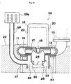
- an underwater agitation pump which is served for the above-mentioned usage, there has been known an underwater agitation pump 100 which has a constitution shown in Fig. 19, for example.
- an impeller casing 101 having a hollow disc-like shape is provided with a center suction opening portion 102 at a center portion of a lower surface thereof and a discharge opening portion 104 which is connected to a discharge pipe 103 at a peripheral portion thereof.
- a disc-like impeller 105 is rotatably disposed in the inside of the impeller casing 101.
- the impeller 105 is provided with a center suction opening portion 106 at a center portion of a lower surface thereof and forms a plurality of radial flow passages 107 in the inside thereof in a circumferentially spaced-apart manner. Further, the impeller 105 is fitted on and is connected to an output shaft 109 of a water-tight motor 108 which is mounted on an upper surface of the impeller casing 101.
- a cylindrical strainer 111 having a bottom wall 110 is contiguously mounted on a lower portion of the impeller casing 101 and an annular support frame 112 is mounted on a lower surface of the cylindrical strainer 111.
- the output shaft 109 of the water-tight motor 108 to which the impeller 105 is fixedly secured is extended downwardly after passing through the center suction opening portion 106 of the impeller 105, the center suction opening portion 102 of the impeller casing 101 and the cylindrical strainer 111 and forms an agitator mounting shaft 113.
- An agitator (cutter fan) 114 which protrudes a plurality of blade members in the radial direction from an outer peripheral surface of a body thereof is fixedly secured to a distal end of the agitator mounting shaft 113.
- a soil/sand inflow effective area A2 is formed of a narrow annular area which is defined between an inner peripheral surface of the center suction opening portion 106 or the center suction opening portion 102 and an outer peripheral surface of the agitator mounting shaft 113.
- the present invention has been made to solve such a drawback and it is an object of the present invention to provide an underwater agitation pump which can reliably and efficiently suck and discharge soil, sand or the like even when the sand, soil or the like includes block-like material or string-like material.
- the underwater agitation pump according to the present invention is arranged as claimed in claim 1, the sub-claims defining preferred embodiments of the invention.
- the proximal end of the agitated material suction guide means is directly communicably connected with the center suction opening portion of the impeller. Accordingly, it becomes possible to make an inner diameter of the agitated material suction guide means substantially equal to an inner diameter of the center suction opening portion of the impeller and an agitator mounting shaft which has been necessary in a conventional underwater agitation pump is made unnecessary, whereby the agitated material suction passage formed in the inside of the agitated material suction guide means can ensure a sufficiently wide agitated material inflow area.
- the outer diameter of the agitated material suction guide means can be remarkably increased so that the winding or the wrapping of the string-like material around the agitated material suction guide cylinder can be reliably prevented.
- the outer diameter of the agitated material suction guide means can be remarkably increased and hence, the section modulus can be remarkably increased so that the mechanical strength of the agitated material suction guide means can be increased whereby it becomes possible to increase the agitator supporting strength and to prevent the rapture or the like of the agitated material suction guide cylinder reliably.
- the distal end opening portion of the agitated material suction guide means which forms an suction opening of the agitated material is formed at a position which is downwardly protruded from the center suction opening portion of the impeller, such a suction opening can be located close to a waterbed compared to an agitated material suction opening of the conventional underwater agitation pump. Accordingly, it becomes possible to simultaneously perform the agitation and the suction of sediment (agitated material). In this manner, while ensuring the sufficiently wide agitated material inflow area in the inside of the agitated material suction guide means, the suction efficiency of the sediment (agitated material) can be further enhanced.
- an underwater agitation pump wherein a strip-like agitator mounting member is provided which spans the distal end opening portion of the agitated material suction guide means, the agitator being fixedly secured to a center portion of the agitator mounting member.
- portions which constitute the distal end opening portion of the agitated material suction guide means and which are disposed at both sides of the agitator mounting member are notched toward the impeller to form a pair of agitated material suction openings.
- the agitation of soil, sand or the like by the agitator and the suction of the soil, sand or the like by the impeller can be simultaneously performed so that the suction and discharge efficiency can be enhanced.
- the soil, sand or the like which contains the string-like material or the block-like material can be smoothly sucked into the impeller casing through the agitated material suction openings and thereafter can be discharged from the impeller casing.
- the agitated material suction guide means can be formed with the impeller by an integral molding
- the agitated material suction guide cylinder can be formed as a body separate from the impeller and can be connected to the impeller by means of bolts.
- the agitated material suction guide cylinder is formed as a body separate from the impeller, a female threaded portion is formed in the center suction opening portion of the impeller, a male threaded portion is formed in the proximal end opening portion of the agitated material suction guide cylinder, and the agitated material suction guide cylinder is connected to the impeller by engaging the male threaded portion with the female threaded portion.
- the agitator By providing the constitution in which the agitator is detachably mounted on the agitator mounting member by means of bolts or the like, when the agitator is worn, the agitator can be easily exchanged. Further, it is unnecessary to exchange the agitator together with the agitated material suction guide cylinder and it is sufficient to exchange only the agitator and hence, the maintenance fee can be reduced.
- the agitated material suction guide means may be comprised of a large-diameter body portion and a stepped distal-end narrowed-diameter portion which constitutes the distal end opening portion, and the agitator is formed by mounting a plurality of triangular agitator constituting members which are extended in the radial direction in a circumferentially spaced apart manner on a stepped portion of the stepped distal-end narrowed-diameter portion.
- the agitator constituting members plays a role of guides for the string-like material so that the entanglement of the string-like material in the agitator can be further reliably prevented.
- the agitator may be mounted on the outer peripheral portion of the distal end opening portion of the agitated material suction guide cylinder by welding or the like, the agitator may be integrally formed with the agitated material suction guide cylinder by molding the distal opening portion of the agitated material suction guide means in a non-circular shape (triangular shape, quadrangular shape, polygonal shape, star-like shape or the like).
- a non-circular shape triangular shape, quadrangular shape, polygonal shape, star-like shape or the like.
- the agitator supporting strength can be increased.
- manufacturing steps can be decreased in number so that they can be manufactured at a low cost.
- a helical feeding blade may be mounted on an inner surface of the agitated material suction guide means.
- the helical feeding blade is integrally rotated so as to generate a lifting force so that the suction efficiency of the underwater agitation pump can be enhanced. Accordingly, even when the agitated material may be made of material having a high-concentration (soil, sand, muddy water or the like of low fluidity having a small water content), the agitated material can be efficiently and reliably sucked.
- a sub water supply pipe which has an upper inlet opening thereof opened in water may have a lower outlet opening thereof disposed in the vicinity of the agitator and directed toward the agitator.
- the soil, sand or the like can be diluted with the sub water so that the soil, sand or the like can be made to smoothly flow into the inside of the agitated material suction guide cylinder.
- a peripheral wall for preventing collapsing and inflow of soil, sand or the like which concentrically surrounds the agitated material suction guide cylinder and has a lower end thereof opened may be contiguously connected to a lower portion of the impeller casing, a water reservoir space may be formed between the agitated material suction guide cylinder and the peripheral wall for preventing collapsing and inflow of soil, sand or the like, and a lower outlet opening of a sub water supply pipe which has an upper inlet opening thereof opened in water may be communicably connected to the water reservoir space.
- the agitation of soil, sand or the like by the agitator and the suction of the soil, sand or the like by the impeller can be simultaneously performed so that the suction and discharge efficiency can be enhanced.
- FIG. 1 is a front view with a part in section of the underwater agitation pump 10 according to the first embodiment of the present invention
- Fig. 2 is a cross-sectional view of Fig. 1 taken along a line I-I
- Fig. 3 is a perspective view showing an impeller, an agitated material suction guide cylinder and an agitator which constitute essential parts of the underwater agitation pump 10.
- an impeller casing 11 having a hollow disc-like shape is provided with a circular center opening 12 at a center portion of a lower surface thereof and a discharge opening portion 14 which is connected to a discharge pipe 13 at a peripheral portion thereof.
- a disc-like impeller 15 is rotatably disposed in the inside of the impeller casing 11.
- the impeller 15 is provided with a circular center suction opening portion 16 at a center portion of a lower surface thereof and a plurality of radial passages 17 are formed in the inside of the impeller 15 in a circumferentially spaced-apart manner.
- the impeller 15 is fitted on and connected to an output shaft 19 of a watertight motor 18 which constitutes a drive source and is mounted on an upper surface of the impeller casing 11.
- numeral 20 indicates a motor casing
- numeral 21 indicates a support base having a mounting frame 21a which is served for mounting and supporting the underwater agitation pump 10 on a bottom surface 22 made of soil, sand or the like.
- an agitated material suction guide cylinder 23 which is constituted of a circular hollow cylinder is disposed concentrically below the impeller casing 11.
- the agitated material suction guide cylinder 23 has proximal end opening portion thereof pass through the center opening 12 of the impeller casing 11 and integrally and communicably connected with the center suction opening portion 16 of the impeller 15 and the distal end opening portion thereof extended downwardly.
- An agitated material suction passage 24 is formed in the inside of the agitated material suction guide cylinder 23.
- an agitator 25 which is served for agitating the soil, sand or the like is mounted on an outer peripheral portion of the distal end opening portion of the agitated material suction guide cylinder 23.
- the diameter (inner diameter) of the agitated material suction guide cylinder 23 can be made substantially equal to the diameter (inner diameter) of the center suction opening portion 16 of the impeller 15 and hence, the agitated material suction guide cylinder 23 can form the agitated material suction passage 24 having the sufficiently large diameter (inner diameter), that is, the sufficiently wide space in the inside thereof.
- the agitated material suction guide cylinder 23 is formed with the impeller 15 by an integral molding as shown in Fig. 1 and Fig. 3.
- the agitated material suction guide cylinder 23 can be mounted on the impeller 15 such that the agitated material suction guide cylinder 23 is formed as a body separate from the impeller 15, a flange 26 is integrally mounted on an outer peripheral surface of proximal end opening portion of the agitated material suction guide cylinder 23, and the flange 26 is connected to the impeller 15 by means of bolts 27.
- Fig. 4 the agitated material suction guide cylinder 23 can be mounted on the impeller 15 such that the agitated material suction guide cylinder 23 is formed as a body separate from the impeller 15, a flange 26 is integrally mounted on an outer peripheral surface of proximal end opening portion of the agitated material suction guide cylinder 23, and the flange 26 is connected to the impeller 15 by means of bolts 27.
- the agitated material suction guide cylinder 23 may be connected to the impeller 15 such that the agitated material suction guide cylinder 23 is formed as a body separate from the impeller 15, a female threaded portion 28 is formed on the center suction opening portion 16 of the impeller 15, a male threaded portion 29 is formed on proximal end opening portion of the agitated material suction guide cylinder 23, and the male threaded portion 29 is engaged with the female threaded portion 28.
- the agitator 25 is constituted such that the agitated material suction guide cylinder 23 is comprised of a large diameter body portion 23a and a stepped distal-end narrowed-diameter portion 23b which constitutes the distal end opening portion, and a plurality of triangular agitator constituting members 30 which are extended in the radial direction in a circumferentially spaced-apart manner are formed on a stepped portion of the stepped distal-end narrowed-diameter portion 23b. Further, the agitator constituting members 30 are respectively mounted with a fixed inclination angle in the circumferential direction.
- the inner diameter of the stepped distal-end narrowed-diameter portion 23b still has a sufficiently large diameter so that the agitated material containing the string-like material or the block-like material can be smoothly sucked into the inside of the agitated material suction guide cylinder 23.
- the shape or structure of the agitator 25 is not limited to those shown in Fig. 1 to Fig. 5 and various shapes and structures can be adopted in view of the nature of soil, sand or the like which forms the bottom surface 22.
- the agitator 25 may take shapes or the structures shown in Fig. 6 to Fig. 11.
- the agitator 25 shown in Fig. 6 and Fig. 7 is constituted such that a plurality of agitator constituting members 31 made of rectangular lugs are mounted on the outer peripheral surface of the distal end opening portion of the agitated material suction guide cylinder 23 which is made of a straight cylinder.
- a flange 32 is mounted on the outer peripheral surface of the distal end opening portion of the agitated material suction guide cylinder 23 which is formed of a straight cylinder and a plurality of agitator constituting members 33 which are extended radially in a circumferentially spaced-apart manner are mounted on the flange 32.
- a plurality of agitator constituting members 33 are inclined in a circumferential direction.
- agitator 11 is constituted such that a plurality of agitator constituting members 34 made of triangular lugs are mounted on the outer peripheral surface of the distal end opening portion of the agitated material suction guide cylinder 23 formed of a tapered cylinder which is narrowed toward a distal end thereof.
- the agitator 25 can be mounted on the outer peripheral portion of the distal end opening portion of the agitated material suction guide cylinder 23 by welding or the like, the agitator 25 can be integrally formed with the agitated material suction guide cylinder 23 also by forming the distal end opening portion of the agitated material suction guide cylinder 25 in a non-circular shape (triangular shape, quadrangular shape, polygonal shape, star-like shape or the like).
- the impeller 15 and the agitator 25 which is integrally connected to the impeller 15 by way of the agitated material suction guide cylinder 23 are rotated together. Accordingly, the inside of the impeller casing 11 becomes a negative pressure and at the same time sand, soil or the like piled up on the bottom surface 22 below the underwater agitation pump 10 is agitated by the agitator 25 and hence, the agitated material is sucked into the inside of the impeller casing 11 through the agitated material suction passage 24 formed in the inside of the agitated material suction guide cylinder 23. Thereafter, the sand, soil or the like is discharged to a desired location through the discharge opening portion 14 and the discharge pipe 13.
- the inner diameter of the agitated material suction guide cylinder 23 can be made approximately equal to the inner diameter of the center suction opening portion 16 of the impeller 15 and the agitator mounting shaft of the conventional underwater agitation pump can be made unnecessary and hence, the agitated material suction passage 24 formed in the inside of the hollow cylinder can have the sufficiently wide agitated material inflow area.
- the sand, soil or the like in which the block-like material or the string-like material is mixed can be sufficiently agitated with the agitator 25 and then can be sucked into the inside of the impeller casing 11 through the agitated material suction guide cylinder 23.
- the outer diameter of the agitated material suction guide cylinder 23 can be also made approximately equal to the inner diameter of the center suction opening portion 16 of the impeller 15, the agitated material suction guide cylinder 23 can ensure the remarkably large outer diameter compared to that of the agitator mounting shaft of the conventional underwater agitation pump which mounts an agitator at a distal end thereof whereby the winding or the wrapping of the string-like material around the agitated material suction guide cylinder 23 can be prevented assuredly.
- the distal end opening portion of the agitated material suction guide cylinder 23 which forms the suction opening for the agitated material can be located at a position protruded downwardly from the center suction opening portion 16 of the impeller 15. Accordingly, it becomes possible to make the distal end opening portion of the agitated material suction guide cylinder 23 face closer to the water bed compared to an agitated material suction opening of the conventional underwater agitation pump whereby the agitation and the suction of the sediment (agitated material) can be simultaneously performed. Coupled with the constitutional feature that the agitated material suction passage 24 can ensure the sufficiently wide agitated material inflow area, the suction efficiency of the sediment (agitated material) can be further enhanced.
- the agitator 25 is comprised of a plurality of triangular agitator constituting members 30 which are extended radially and hence, the agitator constituting members 30 play a role of guides for the string-like material whereby the winding or the wrapping of the string-like material around the agitator 25 can be prevented more assuredly.
- this embodiment is characterized by mounting a helical feeding blade 40 on an inner surface of the agitated material suction guide cylinder 23.
- the helical feeding blade 40 is integrally rotated so that a lifting force is generated whereby the suction efficiency of the underwater agitation pump 10 can be enhanced. Accordingly, even when the agitated material is formed of agitated material having a higher concentration (soil, sand, muddy water or the like which has a little water content and a low fluidity), the agitated material can be efficiently and reliably sucked.
- an underwater agitation pump 50 is characterized in that the underwater agitation pump 10 according to the first embodiment is further provided with a sub water supply pipe 53 which has an upper-end inlet opening 51 thereof opened in water by way of a strainer 52 and has a lower-end outlet opening 54 thereof disposed in the vicinity of the agitator 25 and directed toward the agitator 25.
- constituents elements of the underwater agitation pump 50 which are identical with those of the underwater agitation pump 10 according to the first embodiment are indicated by same numerals.
- numeral 55 indicates a mounting bracket for mounting the sub water supply pipe 53 to the underwater agitation pump 50.
- the underwater agitation pump 50 can obtain, in addition to the advantageous effect obtained by the underwater agitation pump 10 according to the first embodiment that the soil, sand or the like can be smoothly sucked and discharged even when the string-like material or the block-like material is mixed into the soil, sand or the like, an advantageous effect that even when the concentration of the soil, sand or the like is excessively high, the soil, sand or the like can be diluted by the sub water and then is agitated so that the soil, sand or the like can be smoothly sucked into the agitated material suction guide cylinder 23.
- An underwater agitation pump 56 relates to a modification of an underwater agitation pump 10 according to the third embodiment.
- a peripheral wall 57 for preventing collapsing and inflow of soil, sand or the like which concentrically surrounds the agitated material suction guide cylinder 23 and has a lower end thereof opened is contiguously connected to the lower portion of the impeller casing 11.
- the peripheral wall 57 may be preferably made of a solid wall having no apertures.
- a water reservoir space 58 is formed between the agitated material suction guide cylinder 23 and the peripheral wall 57 for preventing collapsing and inflow of soil.
- a sub water supply pipe 59 which has an upper-end inlet opening thereof opened in water by way of a strainer 59a has a lower-end outlet opening thereof communicably connected to the water reservoir space 58.
- constituent elements of the underwater pump 56 which are identical with those of the underwater pump 10 according to the third embodiment are indicated by same numerals.
- An underwater agitation pump relates to a modification of the underwater agitation pump 10 according to the first embodiment.
- this embodiment is characterized in that an agitator 60 is arranged at a center portion of the distal end opening portion of the agitated material suction guide cylinder 23. That is, as shown in the drawings, a strip-like agitator mounting member 61 spans the distal end opening portion of the agitated material suction guide cylinder 23 and an agitator 60 is fixedly secured to a center portion of the agitator mounting member 61.
- portions which constitute the distal end opening portion of the agitated material suction guide cylinder 23 and are disposed at both sides of the agitator mounting member 61 are notched toward the impeller 15 to form a pair of agitated material suction openings 62.
- the agitation of soil, sand or the like by the agitator 60 and the suction of the soil, sand or the like by the impeller 15 can be simultaneously performed so that the suction and discharge efficiency can be enhanced.
- a pair of agitated material suction openings 62 are formed at both sides of the agitator mounting member 61, the soil, sand or the like which contains the string-like material or the block-like material can be smoothly sucked into the impeller casing 11 through the agitated material suction openings 62 and thereafter can be discharged from the impeller casing 11 to a desired location.
- the agitator 60 is detachably mounted on the agitator mounting member 61 by means of bolts or the like, when the agitator 60 is worn, the agitator 60 can be easily exchanged. Further, it is unnecessary to exchange the agitator 60 together with the agitated material suction guide cylinder 23 and it is sufficient to exchange only the agitator 60 and hence, the maintenance fee can be reduced.
- the drive source of the underwater agitation pump is not limited to an electrically-operated motor and includes a hydraulic motor or the like.
- the underwater agitation pump is arranged such that the whole underwater agitation pump is immersed in water in the above-mentioned embodiments, the invention includes the underwater agitation pump which has a portion thereof such as a drive source, for example, disposed above a water level. In this case, it is unnecessary to use a watertight motor.
- the underwater agitation pump may be used not only in the vertical posture as described in the embodiments but also in the inclined posture or in the horizontal posture depending on the use conditions.
Abstract
Description
- The present invention relates to an underwater agitation pump which can suck soil, sand or the like which contains block-like material or string-like material in a dredging site, civil engineering work site, a sewage treatment plant, a sedimentation pool or a pit within a plant, an inside of a manhole or the like while efficiently agitating such soil, sand or the like and can discharge such sand, soil or the like to a given place.
- Conventionally, as an underwater agitation pump which is served for the above-mentioned usage, there has been known an
underwater agitation pump 100 which has a constitution shown in Fig. 19, for example. - As shown in the drawing, in this
underwater agitation pump 100, animpeller casing 101 having a hollow disc-like shape is provided with a centersuction opening portion 102 at a center portion of a lower surface thereof and adischarge opening portion 104 which is connected to adischarge pipe 103 at a peripheral portion thereof. In the inside of theimpeller casing 101, a disc-like impeller 105 is rotatably disposed. Theimpeller 105 is provided with a centersuction opening portion 106 at a center portion of a lower surface thereof and forms a plurality ofradial flow passages 107 in the inside thereof in a circumferentially spaced-apart manner. Further, theimpeller 105 is fitted on and is connected to anoutput shaft 109 of a water-tight motor 108 which is mounted on an upper surface of theimpeller casing 101. - Further, a
cylindrical strainer 111 having abottom wall 110 is contiguously mounted on a lower portion of theimpeller casing 101 and anannular support frame 112 is mounted on a lower surface of thecylindrical strainer 111. - Still further, the
output shaft 109 of the water-tight motor 108 to which theimpeller 105 is fixedly secured is extended downwardly after passing through the centersuction opening portion 106 of theimpeller 105, the centersuction opening portion 102 of theimpeller casing 101 and thecylindrical strainer 111 and forms anagitator mounting shaft 113. An agitator (cutter fan) 114 which protrudes a plurality of blade members in the radial direction from an outer peripheral surface of a body thereof is fixedly secured to a distal end of theagitator mounting shaft 113. - Due to such a constitution, when the
watertight motor 108 is driven, theimpeller 105 and theagitator 114 are integrally rotated so that a negative pressure is generated in the inside of theimpeller casing 101 and soil, sand or the like which is piled up below theunderwater agitation pump 100 is agitated by theagitator 114. Accordingly, the agitated soil, sand or the like is sucked into theimpeller casing 101 through thecylindrical strainer 111 and thereafter is discharged to a desired place through the discharge openingportion 104 and thedischarge pipe 103. - However, the above-mentioned
underwater agitation pump 100 still has a following task to be solved. That is, as shown in Fig. 19, theagitator mounting shaft 113 which mounts theagitator 114 on the distal end thereof passes through the centersuction opening portion 106 of theimpeller 105 and the centersuction opening portion 102 of theimpeller casing 101. Accordingly, as shown in Fig. 20, a soil/sand inflow effective area A2 is formed of a narrow annular area which is defined between an inner peripheral surface of the centersuction opening portion 106 or the centersuction opening portion 102 and an outer peripheral surface of theagitator mounting shaft 113. - Accordingly, when block-like material or string-like material is mixed in the soil, sand or the like, such string-like material or flexible cloths such as vinyl cloths or the like are entangled in the
agitator 114, theagitator mounting shaft 113, thecylindrical strainer 111 or the like and the block-like material and the string-like material clog the soil/sand inflow effective area A2. As a result, the operation of the underwater agitation pump becomes difficult or impossible so that there is a possibility that the soil/sand suction operation becomes difficult or impossible. - The present invention has been made to solve such a drawback and it is an object of the present invention to provide an underwater agitation pump which can reliably and efficiently suck and discharge soil, sand or the like even when the sand, soil or the like includes block-like material or string-like material.
- To achieve the above-mentioned object, the underwater agitation pump according to the present invention is arranged as claimed in
claim 1, the sub-claims defining preferred embodiments of the invention. - In the underwater agitation pump according to the present invention, the proximal end of the agitated material suction guide means is directly communicably connected with the center suction opening portion of the impeller. Accordingly, it becomes possible to make an inner diameter of the agitated material suction guide means substantially equal to an inner diameter of the center suction opening portion of the impeller and an agitator mounting shaft which has been necessary in a conventional underwater agitation pump is made unnecessary, whereby the agitated material suction passage formed in the inside of the agitated material suction guide means can ensure a sufficiently wide agitated material inflow area. Accordingly, it becomes possible to sufficiently agitate soil, sand or the like in which block-like material or string-like material is mixed with use of the agitator and, at the same time, it is possible to smoothly suck such soil, sand or the like in which the block-like material or the string-like material is mixed into the impeller casing through the agitated material suction guide means.
- Further, since it becomes possible to make an outer diameter of the agitated material suction guide means substantially equal to the inner diameter of the center suction opening portion of the impeller, compared to the agitator mounting shaft of the conventional underwater agitation pump which mounts an agitator on a distal end thereof, the outer diameter of the agitated material suction guide means can be remarkably increased so that the winding or the wrapping of the string-like material around the agitated material suction guide cylinder can be reliably prevented. Further, compared to the agitator mounting shaft of the conventional underwater agitation pump, the outer diameter of the agitated material suction guide means can be remarkably increased and hence, the section modulus can be remarkably increased so that the mechanical strength of the agitated material suction guide means can be increased whereby it becomes possible to increase the agitator supporting strength and to prevent the rapture or the like of the agitated material suction guide cylinder reliably.
- Still further, since the distal end opening portion of the agitated material suction guide means which forms an suction opening of the agitated material is formed at a position which is downwardly protruded from the center suction opening portion of the impeller, such a suction opening can be located close to a waterbed compared to an agitated material suction opening of the conventional underwater agitation pump. Accordingly, it becomes possible to simultaneously perform the agitation and the suction of sediment (agitated material). In this manner, while ensuring the sufficiently wide agitated material inflow area in the inside of the agitated material suction guide means, the suction efficiency of the sediment (agitated material) can be further enhanced.
- According to a preferred embodiment of the invention, there is provided an underwater agitation pump wherein a strip-like agitator mounting member is provided which spans the distal end opening portion of the agitated material suction guide means, the agitator being fixedly secured to a center portion of the agitator mounting member. Preferably, portions which constitute the distal end opening portion of the agitated material suction guide means and which are disposed at both sides of the agitator mounting member are notched toward the impeller to form a pair of agitated material suction openings.
- Accordingly, the agitation of soil, sand or the like by the agitator and the suction of the soil, sand or the like by the impeller can be simultaneously performed so that the suction and discharge efficiency can be enhanced.
- Further, along with the advantageous effect above, since a pair of agitated material suction openings are formed at both sides of the agitator mounting member, the soil, sand or the like which contains the string-like material or the block-like material can be smoothly sucked into the impeller casing through the agitated material suction openings and thereafter can be discharged from the impeller casing to the desired location.
- Further, since a pair of agitated material suction openings are formed at both sides of the agitator mounting member, the soil, sand or the like which contains the string-like material or the block-like material can be smoothly sucked into the impeller casing through the agitated material suction openings and thereafter can be discharged from the impeller casing.
- Although the agitated material suction guide means can be formed with the impeller by an integral molding, the agitated material suction guide cylinder can be formed as a body separate from the impeller and can be connected to the impeller by means of bolts. Further, the agitated material suction guide cylinder is formed as a body separate from the impeller, a female threaded portion is formed in the center suction opening portion of the impeller, a male threaded portion is formed in the proximal end opening portion of the agitated material suction guide cylinder, and the agitated material suction guide cylinder is connected to the impeller by engaging the male threaded portion with the female threaded portion. In this manner, when the agitated material suction guide cylinder is constituted of a member separate from the impeller, the constitutions of the impeller and the agitated material suction guide cylinder can be simplified so that they can be manufactured at a low cost.
- By providing the constitution in which the agitator is detachably mounted on the agitator mounting member by means of bolts or the like, when the agitator is worn, the agitator can be easily exchanged. Further, it is unnecessary to exchange the agitator together with the agitated material suction guide cylinder and it is sufficient to exchange only the agitator and hence, the maintenance fee can be reduced.
- The agitated material suction guide means may be comprised of a large-diameter body portion and a stepped distal-end narrowed-diameter portion which constitutes the distal end opening portion, and the agitator is formed by mounting a plurality of triangular agitator constituting members which are extended in the radial direction in a circumferentially spaced apart manner on a stepped portion of the stepped distal-end narrowed-diameter portion. In this case, the agitator constituting members plays a role of guides for the string-like material so that the entanglement of the string-like material in the agitator can be further reliably prevented.
- Although the agitator may be mounted on the outer peripheral portion of the distal end opening portion of the agitated material suction guide cylinder by welding or the like, the agitator may be integrally formed with the agitated material suction guide cylinder by molding the distal opening portion of the agitated material suction guide means in a non-circular shape (triangular shape, quadrangular shape, polygonal shape, star-like shape or the like). In this case, since the agitator can be integrally formed with the agitated material suction guide means, the agitator supporting strength can be increased. Further, since the agitated material suction guide means and the agitator can be integrally formed, manufacturing steps can be decreased in number so that they can be manufactured at a low cost.
- A helical feeding blade may be mounted on an inner surface of the agitated material suction guide means. In this case, along with the rotation of the agitated material suction guide means, the helical feeding blade is integrally rotated so as to generate a lifting force so that the suction efficiency of the underwater agitation pump can be enhanced. Accordingly, even when the agitated material may be made of material having a high-concentration (soil, sand, muddy water or the like of low fluidity having a small water content), the agitated material can be efficiently and reliably sucked.
- A sub water supply pipe which has an upper inlet opening thereof opened in water may have a lower outlet opening thereof disposed in the vicinity of the agitator and directed toward the agitator. In this case, even when the concentration of the soil, sand or the like is excessively high, the soil, sand or the like can be diluted with the sub water so that the soil, sand or the like can be made to smoothly flow into the inside of the agitated material suction guide cylinder.
- A peripheral wall for preventing collapsing and inflow of soil, sand or the like which concentrically surrounds the agitated material suction guide cylinder and has a lower end thereof opened may be contiguously connected to a lower portion of the impeller casing, a water reservoir space may be formed between the agitated material suction guide cylinder and the peripheral wall for preventing collapsing and inflow of soil, sand or the like, and a lower outlet opening of a sub water supply pipe which has an upper inlet opening thereof opened in water may be communicably connected to the water reservoir space. In this case, due to the presence of the peripheral wall for preventing collapsing and inflow of soil, sand or the like, it becomes possible to prevent soil, sand or the like from being collapsed and clogging the distal end opening portion of the agitated material suction guide cylinder which forms a suction opening of the agitated material. Further, due to the presence of the water reservoir space, the soil, sand or the like having a high-concentration can be agitated while being diluted with the sub water and thereafter can be made to smoothly flow into the inside of the agitated material suction guide means.
- Also according to this aspect of the present invention, the agitation of soil, sand or the like by the agitator and the suction of the soil, sand or the like by the impeller can be simultaneously performed so that the suction and discharge efficiency can be enhanced.
- Embodiments of the invention are now described with reference to the drawings, in which:
- Fig. 1 is a front view with a part in cross section of an underwater agitation pump according to the first embodiment of the present invention;
- Fig. 2 is a bottom plan view as viewed from a line I-I of Fig. 1 in an arrow direction;
- Fig. 3 is a perspective view of an impeller and an agitated material suction guide cylinder as viewed from below;
- Fig. 4 is an explanatory view showing the connection state between the impeller and the agitated material suction guide cylinder;
- Fig. 5 is an explanatory view showing the connection state between the impeller and the agitated material suction guide cylinder;
- Fig. 6 is a front view of a modification of the agitator;
- Fig. 7 is a bottom plan view of Fig. 6 as viewed from a line II-II in an arrow direction;
- Fig. 8 is a front view of another modification of the agitator;
- Fig. 9 is a bottom plan view of Fig. 8 as viewed from a line III-III in an arrow direction;
- Fig. 10 is a front view of another modification of the agitator;
- Fig. 11 is a bottom plan view of Fig. 10 as viewed from a line IV-IV in an arrow direction;
- Fig. 12 is an explanatory view of an essential part of an underwater agitation pump according to the second embodiment of the present invention;
- Fig. 13 is a front view with a part in cross section of an underwater agitation pump according to the third embodiment of the present invention;
- Fig. 14 is a bottom plan view of Fig. 13 as viewed from a line V-V in an arrow direction;
- Fig. 15 is a front view with a part in cross section of an underwater agitation pump according to the fourth embodiment of the present invention;
- Fig. 16 is a front view of an agitator according to the fifth embodiment of the present invention;
- Fig. 17 is a bottom plan view of Fig. 16 as viewed from a line VI-VI in an arrow direction;
- Fig. 18 is a side view of Fig. 16 as viewed from a line VII-VII in an arrow direction;
- Fig. 19 is a cross-sectional front view of a conventional underwater agitation pump; and
- Fig. 20 is an explanatory view showing a soil/sand inflow effective area in a conventional underwater agitation pump.
-
- An
underwater agitation pump 10 according to the first embodiment of the present invention is shown in Fig. 1 to Fig. 3. Here, Fig. 1 is a front view with a part in section of theunderwater agitation pump 10 according to the first embodiment of the present invention, Fig. 2 is a cross-sectional view of Fig. 1 taken along a line I-I, and Fig. 3 is a perspective view showing an impeller, an agitated material suction guide cylinder and an agitator which constitute essential parts of theunderwater agitation pump 10. - First of all, to explain the whole constitution of the
underwater agitation pump 10, animpeller casing 11 having a hollow disc-like shape is provided with a circular center opening 12 at a center portion of a lower surface thereof and adischarge opening portion 14 which is connected to adischarge pipe 13 at a peripheral portion thereof. In the inside of theimpeller casing 11, a disc-like impeller 15 is rotatably disposed. Theimpeller 15 is provided with a circular centersuction opening portion 16 at a center portion of a lower surface thereof and a plurality ofradial passages 17 are formed in the inside of theimpeller 15 in a circumferentially spaced-apart manner. Further, theimpeller 15 is fitted on and connected to anoutput shaft 19 of awatertight motor 18 which constitutes a drive source and is mounted on an upper surface of theimpeller casing 11. Here, numeral 20 indicates a motor casing and numeral 21 indicates a support base having a mountingframe 21a which is served for mounting and supporting theunderwater agitation pump 10 on abottom surface 22 made of soil, sand or the like. - Further, an agitated material
suction guide cylinder 23 which is constituted of a circular hollow cylinder is disposed concentrically below theimpeller casing 11. The agitated materialsuction guide cylinder 23 has proximal end opening portion thereof pass through the center opening 12 of theimpeller casing 11 and integrally and communicably connected with the centersuction opening portion 16 of theimpeller 15 and the distal end opening portion thereof extended downwardly. An agitatedmaterial suction passage 24 is formed in the inside of the agitated materialsuction guide cylinder 23. - Further, an
agitator 25 which is served for agitating the soil, sand or the like is mounted on an outer peripheral portion of the distal end opening portion of the agitated materialsuction guide cylinder 23. - With respect to the agitated material
suction guide cylinder 23 having the above-mentioned constitution, the diameter (inner diameter) of the agitated materialsuction guide cylinder 23 can be made substantially equal to the diameter (inner diameter) of the centersuction opening portion 16 of theimpeller 15 and hence, the agitated materialsuction guide cylinder 23 can form the agitatedmaterial suction passage 24 having the sufficiently large diameter (inner diameter), that is, the sufficiently wide space in the inside thereof. - Further, in this embodiment, the agitated material
suction guide cylinder 23 is formed with theimpeller 15 by an integral molding as shown in Fig. 1 and Fig. 3. However, as shown in Fig. 4, the agitated materialsuction guide cylinder 23 can be mounted on theimpeller 15 such that the agitated materialsuction guide cylinder 23 is formed as a body separate from theimpeller 15, aflange 26 is integrally mounted on an outer peripheral surface of proximal end opening portion of the agitated materialsuction guide cylinder 23, and theflange 26 is connected to theimpeller 15 by means ofbolts 27. Further, as shown in Fig. 5, the agitated materialsuction guide cylinder 23 may be connected to theimpeller 15 such that the agitated materialsuction guide cylinder 23 is formed as a body separate from theimpeller 15, a female threadedportion 28 is formed on the centersuction opening portion 16 of theimpeller 15, a male threadedportion 29 is formed on proximal end opening portion of the agitated materialsuction guide cylinder 23, and the male threadedportion 29 is engaged with the female threadedportion 28. - Further, according to this embodiment as shown in Fig. 1 to Fig. 3, the
agitator 25 is constituted such that the agitated materialsuction guide cylinder 23 is comprised of a largediameter body portion 23a and a stepped distal-end narrowed-diameter portion 23b which constitutes the distal end opening portion, and a plurality of triangularagitator constituting members 30 which are extended in the radial direction in a circumferentially spaced-apart manner are formed on a stepped portion of the stepped distal-end narrowed-diameter portion 23b. Further, theagitator constituting members 30 are respectively mounted with a fixed inclination angle in the circumferential direction. Here, the inner diameter of the stepped distal-end narrowed-diameter portion 23b still has a sufficiently large diameter so that the agitated material containing the string-like material or the block-like material can be smoothly sucked into the inside of the agitated materialsuction guide cylinder 23. - The shape or structure of the
agitator 25 is not limited to those shown in Fig. 1 to Fig. 5 and various shapes and structures can be adopted in view of the nature of soil, sand or the like which forms thebottom surface 22. For example, theagitator 25 may take shapes or the structures shown in Fig. 6 to Fig. 11. Theagitator 25 shown in Fig. 6 and Fig. 7 is constituted such that a plurality ofagitator constituting members 31 made of rectangular lugs are mounted on the outer peripheral surface of the distal end opening portion of the agitated materialsuction guide cylinder 23 which is made of a straight cylinder. Theagitator 25 shown in Fig. 8 and Fig. 9 is constituted such that aflange 32 is mounted on the outer peripheral surface of the distal end opening portion of the agitated materialsuction guide cylinder 23 which is formed of a straight cylinder and a plurality ofagitator constituting members 33 which are extended radially in a circumferentially spaced-apart manner are mounted on theflange 32. Here, a plurality ofagitator constituting members 33 are inclined in a circumferential direction. Theagitator 25 shown in Fig. 10 and Fig. 11 is constituted such that a plurality ofagitator constituting members 34 made of triangular lugs are mounted on the outer peripheral surface of the distal end opening portion of the agitated materialsuction guide cylinder 23 formed of a tapered cylinder which is narrowed toward a distal end thereof. Further, although theagitator 25 can be mounted on the outer peripheral portion of the distal end opening portion of the agitated materialsuction guide cylinder 23 by welding or the like, theagitator 25 can be integrally formed with the agitated materialsuction guide cylinder 23 also by forming the distal end opening portion of the agitated materialsuction guide cylinder 25 in a non-circular shape (triangular shape, quadrangular shape, polygonal shape, star-like shape or the like). - Subsequently, the operation for sucking and discharging soil, sand or the like (hereinafter referred to as "soil sucking and discharging operation) using the
underwater agitation pump 10 having the above-mentioned constitution is explained in conjunction with attached drawings, particularly in conjunction with Fig. 1 to Fig. 3. - When the
watertight motor 18 is driven, theimpeller 15 and theagitator 25 which is integrally connected to theimpeller 15 by way of the agitated materialsuction guide cylinder 23 are rotated together. Accordingly, the inside of theimpeller casing 11 becomes a negative pressure and at the same time sand, soil or the like piled up on thebottom surface 22 below theunderwater agitation pump 10 is agitated by theagitator 25 and hence, the agitated material is sucked into the inside of theimpeller casing 11 through the agitatedmaterial suction passage 24 formed in the inside of the agitated materialsuction guide cylinder 23. Thereafter, the sand, soil or the like is discharged to a desired location through thedischarge opening portion 14 and thedischarge pipe 13. - In such a soil sucking and discharging operation, the inner diameter of the agitated material
suction guide cylinder 23 can be made approximately equal to the inner diameter of the centersuction opening portion 16 of theimpeller 15 and the agitator mounting shaft of the conventional underwater agitation pump can be made unnecessary and hence, the agitatedmaterial suction passage 24 formed in the inside of the hollow cylinder can have the sufficiently wide agitated material inflow area. - Accordingly, the sand, soil or the like in which the block-like material or the string-like material is mixed can be sufficiently agitated with the
agitator 25 and then can be sucked into the inside of theimpeller casing 11 through the agitated materialsuction guide cylinder 23. - Further, since the outer diameter of the agitated material
suction guide cylinder 23 can be also made approximately equal to the inner diameter of the centersuction opening portion 16 of theimpeller 15, the agitated materialsuction guide cylinder 23 can ensure the remarkably large outer diameter compared to that of the agitator mounting shaft of the conventional underwater agitation pump which mounts an agitator at a distal end thereof whereby the winding or the wrapping of the string-like material around the agitated materialsuction guide cylinder 23 can be prevented assuredly. - Further, the distal end opening portion of the agitated material
suction guide cylinder 23 which forms the suction opening for the agitated material can be located at a position protruded downwardly from the centersuction opening portion 16 of theimpeller 15. Accordingly, it becomes possible to make the distal end opening portion of the agitated materialsuction guide cylinder 23 face closer to the water bed compared to an agitated material suction opening of the conventional underwater agitation pump whereby the agitation and the suction of the sediment (agitated material) can be simultaneously performed. Coupled with the constitutional feature that the agitatedmaterial suction passage 24 can ensure the sufficiently wide agitated material inflow area, the suction efficiency of the sediment (agitated material) can be further enhanced. - Further, as shown in Fig. 1 to Fig. 5, in this embodiment, the
agitator 25 is comprised of a plurality of triangularagitator constituting members 30 which are extended radially and hence, theagitator constituting members 30 play a role of guides for the string-like material whereby the winding or the wrapping of the string-like material around theagitator 25 can be prevented more assuredly. - As shown in Fig. 12, this embodiment is characterized by mounting a
helical feeding blade 40 on an inner surface of the agitated materialsuction guide cylinder 23. In this embodiment, along with the rotation of the agitated materialsuction guide cylinder 23, thehelical feeding blade 40 is integrally rotated so that a lifting force is generated whereby the suction efficiency of theunderwater agitation pump 10 can be enhanced. Accordingly, even when the agitated material is formed of agitated material having a higher concentration (soil, sand, muddy water or the like which has a little water content and a low fluidity), the agitated material can be efficiently and reliably sucked. - As shown in Fig. 13 and Fig. 14, an
underwater agitation pump 50 according to this embodiment is characterized in that theunderwater agitation pump 10 according to the first embodiment is further provided with a subwater supply pipe 53 which has an upper-end inlet opening 51 thereof opened in water by way of astrainer 52 and has a lower-end outlet opening 54 thereof disposed in the vicinity of theagitator 25 and directed toward theagitator 25. Here, constituents elements of theunderwater agitation pump 50 which are identical with those of theunderwater agitation pump 10 according to the first embodiment are indicated by same numerals. Further, in the drawing, numeral 55 indicates a mounting bracket for mounting the subwater supply pipe 53 to theunderwater agitation pump 50. - Due to the above-mentioned constitution, the
underwater agitation pump 50 according to this embodiment can obtain, in addition to the advantageous effect obtained by theunderwater agitation pump 10 according to the first embodiment that the soil, sand or the like can be smoothly sucked and discharged even when the string-like material or the block-like material is mixed into the soil, sand or the like, an advantageous effect that even when the concentration of the soil, sand or the like is excessively high, the soil, sand or the like can be diluted by the sub water and then is agitated so that the soil, sand or the like can be smoothly sucked into the agitated materialsuction guide cylinder 23. - An
underwater agitation pump 56 according to this embodiment relates to a modification of anunderwater agitation pump 10 according to the third embodiment. To be more specific, as shown in Fig. 15, aperipheral wall 57 for preventing collapsing and inflow of soil, sand or the like which concentrically surrounds the agitated materialsuction guide cylinder 23 and has a lower end thereof opened is contiguously connected to the lower portion of theimpeller casing 11. Theperipheral wall 57 may be preferably made of a solid wall having no apertures. Awater reservoir space 58 is formed between the agitated materialsuction guide cylinder 23 and theperipheral wall 57 for preventing collapsing and inflow of soil. A subwater supply pipe 59 which has an upper-end inlet opening thereof opened in water by way of astrainer 59a has a lower-end outlet opening thereof communicably connected to thewater reservoir space 58. Here, constituent elements of theunderwater pump 56 which are identical with those of theunderwater pump 10 according to the third embodiment are indicated by same numerals. - In this case, with the provision of the
peripheral wall 57 for preventing collapsing and inflow of soil, sand or the like, at the time of starting the operation of theunderwater agitation pump 56, it becomes possible to prevent the distal end opening portion of the agitated materialsuction guide cylinder 23 which forms the suction opening for the agitated material from being clogged by the collapsed soil, sand or the like. Simultaneously, with the provision of thewater reservoir space 58, it becomes possible to make the soil, sand or the like having a high concentration smoothly flow into the inside of the agitated materialsuction guide cylinder 23 after diluting such soil, sand or the like with sub water. - An underwater agitation pump according to this embodiment relates to a modification of the
underwater agitation pump 10 according to the first embodiment. To be more specific, as shown in Fig. 16 to Fig. 18, this embodiment is characterized in that anagitator 60 is arranged at a center portion of the distal end opening portion of the agitated materialsuction guide cylinder 23. That is, as shown in the drawings, a strip-likeagitator mounting member 61 spans the distal end opening portion of the agitated materialsuction guide cylinder 23 and anagitator 60 is fixedly secured to a center portion of theagitator mounting member 61. Further, portions which constitute the distal end opening portion of the agitated materialsuction guide cylinder 23 and are disposed at both sides of theagitator mounting member 61 are notched toward theimpeller 15 to form a pair of agitatedmaterial suction openings 62. - Also in this embodiment, the agitation of soil, sand or the like by the
agitator 60 and the suction of the soil, sand or the like by theimpeller 15 can be simultaneously performed so that the suction and discharge efficiency can be enhanced. Further, since a pair of agitatedmaterial suction openings 62 are formed at both sides of theagitator mounting member 61, the soil, sand or the like which contains the string-like material or the block-like material can be smoothly sucked into theimpeller casing 11 through the agitatedmaterial suction openings 62 and thereafter can be discharged from theimpeller casing 11 to a desired location. - Further, by providing a constitution in which the
agitator 60 is detachably mounted on theagitator mounting member 61 by means of bolts or the like, when theagitator 60 is worn, theagitator 60 can be easily exchanged. Further, it is unnecessary to exchange theagitator 60 together with the agitated materialsuction guide cylinder 23 and it is sufficient to exchange only theagitator 60 and hence, the maintenance fee can be reduced. - As has been described heretofore, according to the present invention, following advantageous effects can be obtained.
- Although the inventions have been explained specifically in conjunction with several embodiments, the present inventions are not limited to the above-mentioned embodiments and includes other embodiments and modifications without departing from the scope of the inventions defined by scope of patent claims. For example, the drive source of the underwater agitation pump is not limited to an electrically-operated motor and includes a hydraulic motor or the like. Further, although the underwater agitation pump is arranged such that the whole underwater agitation pump is immersed in water in the above-mentioned embodiments, the invention includes the underwater agitation pump which has a portion thereof such as a drive source, for example, disposed above a water level. In this case, it is unnecessary to use a watertight motor. Still, further, the underwater agitation pump may be used not only in the vertical posture as described in the embodiments but also in the inclined posture or in the horizontal posture depending on the use conditions.
Claims (11)
- An underwater agitation pump comprising:an impeller casing in which an impeller is accommodated;an agitated material suction guide means which has a proximal opening portion connected to a center suction opening portion of the impeller and a distal end opening portion extending away from the impeller, the agitated material suction guide means further forming an agitated material suction passage in the inside thereof; andan agitator which is mounted at the distal opening portion of the agitated material suction guide means.
- An underwater agitation pump according to claim 1, wherein the agitated material suction guide means comprise a hollow cylinder.
- An underwater agitation pump according to claim 1 or 2, wherein the agitator is mounted on an outer periphery of the distal end of the agitated material suction guide means.
- An underwater agitation pump according to claim 1 or 2, wherein a strip-like agitator mounting member is provided which spans the distal end opening portion of the agitated material suction guide means, the agitator being fixedly secured to a center portion of the agitator mounting member.
- An underwater agitation pump according to claim 4, wherein portions which constitute the distal end opening portion of the agitated material suction guide means and which are disposed at both sides of the agitator mounting member are notched toward the impeller to form a pair of agitated material suction openings.
- An underwater agitation pump according to any of the preceding claims, wherein the agitated material suction guide means is connected to the impeller by integrally molding the agitated material suction guide means and the impeller or by means of bolts between the agitated material suction guide means and the impeller or by a thread connection between the agitated material suction guide means and the impeller.
- An underwater agitation pump according to any one of preceding claims, wherein the agitated material suction guide means is comprised of a large-diameter body portion and a stepped distal-end narrowed-diameter portion which constitutes the distal end opening portion, and the agitator is formed by mounting a plurality of triangular agitator constituting members which are extended in the radial direction in a circumferentially spaced apart manner on a stepped portion of the stepped distal end narrowed-diameter portion.
- An underwater agitation pump according to any one of preceding claims, wherein the agitator is formed by molding the distal end opening portion of the agitated material suction guide cylinder in a non-circular shape.
- An underwater agitation pump according to any one of preceding claims, wherein a helical feeding blade is mounted on an inner surface of the agitated material suction guide cylinder.
- An underwater agitation pump according to any one of preceding claims, wherein a sub water supply pipe which has an upper inlet opening thereof opened in water has a lower outlet opening thereof disposed in the vicinity of the agitator and directed toward the agitator.
- An underwater agitation pump according to any one of preceding claims, wherein a peripheral wall for preventing collapsing and inflow of soil, sand or the like which concentrically surrounds the agitated material suction guide sleeve and has a lower end thereof opened is contiguously connected to a lower portion of the impeller casing, a water reservoir space is formed between the agitated material suction guide cylinder and the peripheral wall for preventing collapsing and inflow of soil, sand or the like, and a lower outlet opening of a sub water supply pipe which has an upper inlet opening thereof opened in water is communicably connected to the water reservoir space.
Applications Claiming Priority (2)
| Application Number | Priority Date | Filing Date | Title |
|---|---|---|---|
| JP2001185521 | 2001-06-19 | ||
| JP2001185521A JP3672505B2 (en) | 2001-06-19 | 2001-06-19 | Submersible agitation pump |
Publications (3)
| Publication Number | Publication Date |
|---|---|
| EP1270952A2 true EP1270952A2 (en) | 2003-01-02 |
| EP1270952A3 EP1270952A3 (en) | 2004-01-07 |
| EP1270952B1 EP1270952B1 (en) | 2006-02-08 |
Family
ID=19025083
Family Applications (1)
| Application Number | Title | Priority Date | Filing Date |
|---|---|---|---|
| EP01120285A Expired - Lifetime EP1270952B1 (en) | 2001-06-19 | 2001-08-23 | Stirring pump |
Country Status (11)
| Country | Link |
|---|---|
| US (1) | US6698916B2 (en) |
| EP (1) | EP1270952B1 (en) |
| JP (1) | JP3672505B2 (en) |
| KR (1) | KR100855729B1 (en) |
| CN (1) | CN1293308C (en) |
| AT (1) | ATE317500T1 (en) |
| AU (1) | AU783654B2 (en) |
| CA (1) | CA2363610C (en) |
| DE (1) | DE60117076T2 (en) |
| TW (1) | TW539811B (en) |
| ZA (1) | ZA200107419B (en) |
Cited By (4)
| Publication number | Priority date | Publication date | Assignee | Title |
|---|---|---|---|---|
| EP1270826B1 (en) * | 2001-06-29 | 2007-02-28 | Toyo Denki Industrial Co., Ltd. | Gravel-or-the-like removing device |
| EP2153071A1 (en) * | 2007-05-21 | 2010-02-17 | Weir Minerals Australia Ltd | Improvements in and relating to pumps |
| AU2016201972B2 (en) * | 2007-05-21 | 2017-11-16 | Weir Minerals Australia Ltd | Improvements in and relating to pumps |
| US9863440B2 (en) | 2014-06-26 | 2018-01-09 | Dragflow S.R.L. | Submersible pump |
Families Citing this family (13)
| Publication number | Priority date | Publication date | Assignee | Title |
|---|---|---|---|---|
| JP3672505B2 (en) * | 2001-06-19 | 2005-07-20 | 株式会社東洋電機工業所 | Submersible agitation pump |
| KR20050038710A (en) * | 2003-10-22 | 2005-04-29 | 삼성전자주식회사 | Blower and air conditioner with the same |
| JP5646834B2 (en) * | 2009-10-13 | 2014-12-24 | 株式会社Mgグローアップ | Mixing and stirring device |
| CN102434492A (en) * | 2011-12-22 | 2012-05-02 | 上海成峰流体设备有限公司 | Stirring pump base with two layers of spaces |
| JP6113418B2 (en) * | 2012-05-02 | 2017-04-12 | 株式会社エディプラス | Submersible pump |
| CN102995886A (en) * | 2012-10-07 | 2013-03-27 | 仇英兰 | Minitype mortar stirring and conveying machine |
| KR101531017B1 (en) * | 2013-12-05 | 2015-06-23 | 주식회사 전진 | Underwater pump |
| CN103850975A (en) * | 2014-04-01 | 2014-06-11 | 山东大博泵业科技有限公司 | Clutch type stirring device for preventing slurry from being solidified and hardened of vertical type mortar pump |
| US11031149B1 (en) * | 2018-02-13 | 2021-06-08 | AGI Engineering, Inc. | Nuclear abrasive slurry waste pump with backstop and macerator |
| KR200493504Y1 (en) * | 2020-08-06 | 2021-04-12 | 국립공원공단 | Marine float collector |
| CA3187642A1 (en) * | 2020-08-31 | 2022-03-03 | Cesar Calma | Pump apparatus for reducing the size of suspended solids before pumping |
| CN112943684B (en) * | 2021-02-07 | 2022-12-27 | 武汉船用机械有限责任公司 | Deep well immersed pump impeller auxiliary device and pump head |
| KR102527881B1 (en) * | 2022-11-18 | 2023-05-02 | (주)한국펌프앤시스템즈 | Submersible pump with rotating suction guide base |
Citations (6)
| Publication number | Priority date | Publication date | Assignee | Title |
|---|---|---|---|---|
| AT219420B (en) * | 1960-03-13 | 1962-01-25 | Bauer Roehren Pumpen | Device for stirring and / or conveying the contents of a cesspool or the like. |
| DE1944639U (en) * | 1964-02-14 | 1966-08-18 | Boelkow Gmbh | CENTRIFUGAL PUMP RUNNER. |
| US3367539A (en) * | 1967-03-30 | 1968-02-06 | Franklin W. Dowdican | Waste lift pump with inlet clearing by-pass conduit |
| GB2070687A (en) * | 1980-02-19 | 1981-09-09 | Toyo Denki Kogyosho Co Ltd | Improvements in or relating to fluid agitator assemblies |
| US4640666A (en) * | 1982-10-11 | 1987-02-03 | International Standard Electric Corporation | Centrifugal pump |
| DE19539564C1 (en) * | 1995-10-25 | 1996-06-27 | Orpu Gmbh | Pump with impurity cutting device arranged in suction connection |
Family Cites Families (26)
| Publication number | Priority date | Publication date | Assignee | Title |
|---|---|---|---|---|
| US1769257A (en) * | 1930-07-01 | demaree | ||
| US1668063A (en) * | 1927-05-10 | 1928-05-01 | John W Force | Cleaning device for oil tanks and the like |
| US2376071A (en) * | 1940-08-27 | 1945-05-15 | Miess Fred | Centrifugal pump |
| US2555619A (en) * | 1946-05-11 | 1951-06-05 | Continental Aviat & Engineerin | Pump |
| US2622858A (en) * | 1948-04-22 | 1952-12-23 | Infilco Inc | Apparatus for submerged gas diffusion |
| US2701529A (en) * | 1952-04-08 | 1955-02-08 | Weil Pump Co | Submersible sump pump |
| FR2032189A5 (en) * | 1969-02-21 | 1970-11-20 | Guinard Pompes | |
| US3718957A (en) * | 1970-09-03 | 1973-03-06 | Avco Corp | Method of securing a threaded element in a high centrifugal force field |
| ES383567A1 (en) * | 1970-09-11 | 1974-06-01 | Sener Tecnica Ind Naval S A | New type of rotary pump for liquids |
| JPS50105607U (en) * | 1974-02-01 | 1975-08-30 | ||
| JPS5330652A (en) | 1976-08-27 | 1978-03-23 | Sankyo Yuki Gosei Kk | Stabilization of vinyl chloride resins |
| JPS5430652A (en) * | 1977-08-09 | 1979-03-07 | Toyo Denki Kougiyoushiyo Kk | Method of removing mud accumulated in vertical hole as manhole or like |
| NL8102875A (en) * | 1980-06-26 | 1982-01-18 | Toyo Denki Kogyosho Co Ltd | METHOD AND MECHANISM FOR CONTROLLING PRESSURE ON AXLE SEALING PART OF AN APPARATUS. |
| US4456424A (en) * | 1981-03-05 | 1984-06-26 | Toyo Denki Kogyosho Co., Ltd. | Underwater sand pump |
| JPS6226399A (en) * | 1985-07-26 | 1987-02-04 | Toyo Denki Kogyosho:Kk | Submersible pump |
| US5005364A (en) * | 1990-02-07 | 1991-04-09 | Nelson William R | Apparatus for and method of making and delivering slush ice |
| JP3079271B2 (en) * | 1993-07-23 | 2000-08-21 | 株式会社関水社 | Vertical pull-out type self-priming pump |
| KR960003984B1 (en) * | 1993-08-28 | 1996-03-25 | 최기호 | Message recording set for telephone for audio response unit |
| KR950027869U (en) * | 1994-03-31 | 1995-10-18 | Drainage Submersible Pump | |
| JP3554635B2 (en) * | 1996-06-18 | 2004-08-18 | 株式会社東洋電機工業所 | Submersible pump with stirring suppression function |
| KR980003714U (en) * | 1996-06-21 | 1998-03-30 | Volute type shallow submersible pump with rubber impeller casing | |
| KR19980032604U (en) * | 1996-12-04 | 1998-09-05 | 구자홍 | Intrusion prevention structure of submerged pump |
| FI111023B (en) * | 1998-12-30 | 2003-05-15 | Sulzer Pumpen Ag | Method and apparatus for pumping material and rotor used in connection with the apparatus |
| JP3310635B2 (en) * | 1999-07-30 | 2002-08-05 | 株式会社栗本鐵工所 | Casing structure of submersible pump for sand sampling |
| CN2390034Y (en) * | 1999-09-21 | 2000-08-02 | 徐兆征 | Impurities pump |
| JP3672505B2 (en) * | 2001-06-19 | 2005-07-20 | 株式会社東洋電機工業所 | Submersible agitation pump |
-
2001
- 2001-06-19 JP JP2001185521A patent/JP3672505B2/en not_active Expired - Fee Related
- 2001-07-27 TW TW090118365A patent/TW539811B/en not_active IP Right Cessation
- 2001-08-03 KR KR1020010047075A patent/KR100855729B1/en active IP Right Grant
- 2001-08-21 US US09/933,126 patent/US6698916B2/en not_active Expired - Lifetime
- 2001-08-23 EP EP01120285A patent/EP1270952B1/en not_active Expired - Lifetime
- 2001-08-23 DE DE60117076T patent/DE60117076T2/en not_active Expired - Lifetime
- 2001-08-23 AT AT01120285T patent/ATE317500T1/en not_active IP Right Cessation
- 2001-08-23 AU AU63606/01A patent/AU783654B2/en not_active Ceased
- 2001-09-05 CN CNB011311770A patent/CN1293308C/en not_active Expired - Lifetime
- 2001-09-07 ZA ZA200107419A patent/ZA200107419B/en unknown
- 2001-11-22 CA CA2363610A patent/CA2363610C/en not_active Expired - Lifetime
Patent Citations (6)
| Publication number | Priority date | Publication date | Assignee | Title |
|---|---|---|---|---|
| AT219420B (en) * | 1960-03-13 | 1962-01-25 | Bauer Roehren Pumpen | Device for stirring and / or conveying the contents of a cesspool or the like. |
| DE1944639U (en) * | 1964-02-14 | 1966-08-18 | Boelkow Gmbh | CENTRIFUGAL PUMP RUNNER. |
| US3367539A (en) * | 1967-03-30 | 1968-02-06 | Franklin W. Dowdican | Waste lift pump with inlet clearing by-pass conduit |
| GB2070687A (en) * | 1980-02-19 | 1981-09-09 | Toyo Denki Kogyosho Co Ltd | Improvements in or relating to fluid agitator assemblies |
| US4640666A (en) * | 1982-10-11 | 1987-02-03 | International Standard Electric Corporation | Centrifugal pump |
| DE19539564C1 (en) * | 1995-10-25 | 1996-06-27 | Orpu Gmbh | Pump with impurity cutting device arranged in suction connection |
Cited By (7)
| Publication number | Priority date | Publication date | Assignee | Title |
|---|---|---|---|---|
| EP1270826B1 (en) * | 2001-06-29 | 2007-02-28 | Toyo Denki Industrial Co., Ltd. | Gravel-or-the-like removing device |
| EP2153071A1 (en) * | 2007-05-21 | 2010-02-17 | Weir Minerals Australia Ltd | Improvements in and relating to pumps |
| EP2153071A4 (en) * | 2007-05-21 | 2014-07-30 | Weir Minerals Australia Ltd | Improvements in and relating to pumps |
| AU2016201972B2 (en) * | 2007-05-21 | 2017-11-16 | Weir Minerals Australia Ltd | Improvements in and relating to pumps |
| US9897090B2 (en) | 2007-05-21 | 2018-02-20 | Weir Minerals Australia Ltd. | Pumps |
| US11274669B2 (en) | 2007-05-21 | 2022-03-15 | Weir Minerals Australia Ltd. | Relating to pumps |
| US9863440B2 (en) | 2014-06-26 | 2018-01-09 | Dragflow S.R.L. | Submersible pump |
Also Published As
| Publication number | Publication date |
|---|---|
| US20020191488A1 (en) | 2002-12-19 |
| DE60117076D1 (en) | 2006-04-20 |
| CA2363610A1 (en) | 2002-12-19 |
| DE60117076T2 (en) | 2006-07-13 |
| AU6360601A (en) | 2003-01-02 |
| KR100855729B1 (en) | 2008-09-03 |
| ATE317500T1 (en) | 2006-02-15 |
| JP3672505B2 (en) | 2005-07-20 |
| CA2363610C (en) | 2010-01-26 |
| JP2003003982A (en) | 2003-01-08 |
| KR20020096806A (en) | 2002-12-31 |
| EP1270952A3 (en) | 2004-01-07 |
| AU783654B2 (en) | 2005-11-24 |
| CN1392347A (en) | 2003-01-22 |
| EP1270952B1 (en) | 2006-02-08 |
| ZA200107419B (en) | 2002-03-12 |
| US6698916B2 (en) | 2004-03-02 |
| CN1293308C (en) | 2007-01-03 |
| TW539811B (en) | 2003-07-01 |
Similar Documents
| Publication | Publication Date | Title |
|---|---|---|
| CA2363610C (en) | Underwater agitation pump | |
| EP1270826B1 (en) | Gravel-or-the-like removing device | |
| US9897090B2 (en) | Pumps | |
| EP2960375A1 (en) | Submersible pump | |
| KR101254873B1 (en) | Areation Aapparatus | |
| JP5618392B1 (en) | Fluid stirring device and sand pump using the same | |
| JP4301429B2 (en) | Submersible agitation pump | |
| JP4601047B2 (en) | Disturbance pump | |
| JP3828061B2 (en) | Underwater aerator | |
| CN210960082U (en) | Rice field water direct-supply type plant protection pesticide mixing device | |
| JP4726184B2 (en) | Disturbance pump | |
| AU2013202767A1 (en) | Improvements in and relating to pumps | |
| CN110622943A (en) | Rice field water direct-supply type plant protection pesticide mixing device | |
| JP2001289178A (en) | Storage pump |
Legal Events
| Date | Code | Title | Description |
|---|---|---|---|
| PUAI | Public reference made under article 153(3) epc to a published international application that has entered the european phase |
Free format text: ORIGINAL CODE: 0009012 |
|
| AK | Designated contracting states |
Kind code of ref document: A2 Designated state(s): AT BE CH CY DE DK ES FI FR GB GR IE IT LI LU MC NL PT SE TR |
|
| AX | Request for extension of the european patent |
Free format text: AL;LT;LV;MK;RO;SI |
|
| PUAL | Search report despatched |
Free format text: ORIGINAL CODE: 0009013 |
|
| AK | Designated contracting states |
Kind code of ref document: A3 Designated state(s): AT BE CH CY DE DK ES FI FR GB GR IE IT LI LU MC NL PT SE TR |
|
| AX | Request for extension of the european patent |
Extension state: AL LT LV MK RO SI |
|
| RAP1 | Party data changed (applicant data changed or rights of an application transferred) |
Owner name: TOYO DENKI INDUSTRIAL CO., LTD. |
|
| 17P | Request for examination filed |
Effective date: 20040623 |
|
| AKX | Designation fees paid |
Designated state(s): AT BE CH CY DE DK ES FI FR GB GR IE IT LI LU MC NL PT SE TR |
|
| 17Q | First examination report despatched |
Effective date: 20041119 |
|
| GRAP | Despatch of communication of intention to grant a patent |
Free format text: ORIGINAL CODE: EPIDOSNIGR1 |
|
| GRAS | Grant fee paid |
Free format text: ORIGINAL CODE: EPIDOSNIGR3 |
|
| GRAA | (expected) grant |
Free format text: ORIGINAL CODE: 0009210 |
|
| AK | Designated contracting states |
Kind code of ref document: B1 Designated state(s): AT BE CH CY DE DK ES FI FR GB GR IE IT LI LU MC NL PT SE TR |
|
| PG25 | Lapsed in a contracting state [announced via postgrant information from national office to epo] |
Ref country code: FI Free format text: LAPSE BECAUSE OF FAILURE TO SUBMIT A TRANSLATION OF THE DESCRIPTION OR TO PAY THE FEE WITHIN THE PRESCRIBED TIME-LIMIT Effective date: 20060208 Ref country code: AT Free format text: LAPSE BECAUSE OF FAILURE TO SUBMIT A TRANSLATION OF THE DESCRIPTION OR TO PAY THE FEE WITHIN THE PRESCRIBED TIME-LIMIT Effective date: 20060208 Ref country code: CH Free format text: LAPSE BECAUSE OF FAILURE TO SUBMIT A TRANSLATION OF THE DESCRIPTION OR TO PAY THE FEE WITHIN THE PRESCRIBED TIME-LIMIT Effective date: 20060208 Ref country code: LI Free format text: LAPSE BECAUSE OF FAILURE TO SUBMIT A TRANSLATION OF THE DESCRIPTION OR TO PAY THE FEE WITHIN THE PRESCRIBED TIME-LIMIT Effective date: 20060208 |
|
| REG | Reference to a national code |
Ref country code: GB Ref legal event code: FG4D |
|
| REG | Reference to a national code |
Ref country code: CH Ref legal event code: EP |
|
| REG | Reference to a national code |
Ref country code: IE Ref legal event code: FG4D |
|
| REF | Corresponds to: |
Ref document number: 60117076 Country of ref document: DE Date of ref document: 20060420 Kind code of ref document: P |
|
| PG25 | Lapsed in a contracting state [announced via postgrant information from national office to epo] |
Ref country code: DK Free format text: LAPSE BECAUSE OF FAILURE TO SUBMIT A TRANSLATION OF THE DESCRIPTION OR TO PAY THE FEE WITHIN THE PRESCRIBED TIME-LIMIT Effective date: 20060508 Ref country code: SE Free format text: LAPSE BECAUSE OF FAILURE TO SUBMIT A TRANSLATION OF THE DESCRIPTION OR TO PAY THE FEE WITHIN THE PRESCRIBED TIME-LIMIT Effective date: 20060508 |
|
| PG25 | Lapsed in a contracting state [announced via postgrant information from national office to epo] |
Ref country code: ES Free format text: LAPSE BECAUSE OF FAILURE TO SUBMIT A TRANSLATION OF THE DESCRIPTION OR TO PAY THE FEE WITHIN THE PRESCRIBED TIME-LIMIT Effective date: 20060519 |
|
| PG25 | Lapsed in a contracting state [announced via postgrant information from national office to epo] |
Ref country code: PT Free format text: LAPSE BECAUSE OF FAILURE TO SUBMIT A TRANSLATION OF THE DESCRIPTION OR TO PAY THE FEE WITHIN THE PRESCRIBED TIME-LIMIT Effective date: 20060710 |
|
| ET | Fr: translation filed | ||
| REG | Reference to a national code |
Ref country code: CH Ref legal event code: PL |
|
| PG25 | Lapsed in a contracting state [announced via postgrant information from national office to epo] |
Ref country code: IE Free format text: LAPSE BECAUSE OF NON-PAYMENT OF DUE FEES Effective date: 20060823 |
|
| PG25 | Lapsed in a contracting state [announced via postgrant information from national office to epo] |
Ref country code: MC Free format text: LAPSE BECAUSE OF NON-PAYMENT OF DUE FEES Effective date: 20060831 |
|
| PLBE | No opposition filed within time limit |
Free format text: ORIGINAL CODE: 0009261 |
|
| STAA | Information on the status of an ep patent application or granted ep patent |
Free format text: STATUS: NO OPPOSITION FILED WITHIN TIME LIMIT |
|
| 26N | No opposition filed |
Effective date: 20061109 |
|
| PG25 | Lapsed in a contracting state [announced via postgrant information from national office to epo] |
Ref country code: GR Free format text: LAPSE BECAUSE OF FAILURE TO SUBMIT A TRANSLATION OF THE DESCRIPTION OR TO PAY THE FEE WITHIN THE PRESCRIBED TIME-LIMIT Effective date: 20060509 |
|
| PG25 | Lapsed in a contracting state [announced via postgrant information from national office to epo] |
Ref country code: TR Free format text: LAPSE BECAUSE OF FAILURE TO SUBMIT A TRANSLATION OF THE DESCRIPTION OR TO PAY THE FEE WITHIN THE PRESCRIBED TIME-LIMIT Effective date: 20060208 Ref country code: LU Free format text: LAPSE BECAUSE OF NON-PAYMENT OF DUE FEES Effective date: 20060823 |
|
| PG25 | Lapsed in a contracting state [announced via postgrant information from national office to epo] |
Ref country code: CY Free format text: LAPSE BECAUSE OF FAILURE TO SUBMIT A TRANSLATION OF THE DESCRIPTION OR TO PAY THE FEE WITHIN THE PRESCRIBED TIME-LIMIT Effective date: 20060208 |
|
| REG | Reference to a national code |
Ref country code: FR Ref legal event code: PLFP Year of fee payment: 16 |
|
| REG | Reference to a national code |
Ref country code: FR Ref legal event code: PLFP Year of fee payment: 17 |
|
| PGFP | Annual fee paid to national office [announced via postgrant information from national office to epo] |
Ref country code: NL Payment date: 20170823 Year of fee payment: 17 |
|
| PGFP | Annual fee paid to national office [announced via postgrant information from national office to epo] |
Ref country code: IT Payment date: 20170824 Year of fee payment: 17 Ref country code: GB Payment date: 20170824 Year of fee payment: 17 |
|
| REG | Reference to a national code |
Ref country code: FR Ref legal event code: PLFP Year of fee payment: 18 |
|
| REG | Reference to a national code |
Ref country code: NL Ref legal event code: MM Effective date: 20180901 |
|
| GBPC | Gb: european patent ceased through non-payment of renewal fee |
Effective date: 20180823 |
|
| PG25 | Lapsed in a contracting state [announced via postgrant information from national office to epo] |
Ref country code: NL Free format text: LAPSE BECAUSE OF NON-PAYMENT OF DUE FEES Effective date: 20180901 |
|
| PG25 | Lapsed in a contracting state [announced via postgrant information from national office to epo] |
Ref country code: IT Free format text: LAPSE BECAUSE OF NON-PAYMENT OF DUE FEES Effective date: 20180823 |
|
| PG25 | Lapsed in a contracting state [announced via postgrant information from national office to epo] |
Ref country code: GB Free format text: LAPSE BECAUSE OF NON-PAYMENT OF DUE FEES Effective date: 20180823 |
|
| PGFP | Annual fee paid to national office [announced via postgrant information from national office to epo] |
Ref country code: FR Payment date: 20190822 Year of fee payment: 19 |
|
| PGFP | Annual fee paid to national office [announced via postgrant information from national office to epo] |
Ref country code: BE Payment date: 20190821 Year of fee payment: 19 |
|
| PGFP | Annual fee paid to national office [announced via postgrant information from national office to epo] |
Ref country code: DE Payment date: 20191023 Year of fee payment: 19 |
|
| REG | Reference to a national code |
Ref country code: DE Ref legal event code: R119 Ref document number: 60117076 Country of ref document: DE |
|
| REG | Reference to a national code |
Ref country code: BE Ref legal event code: MM Effective date: 20200831 |
|
| PG25 | Lapsed in a contracting state [announced via postgrant information from national office to epo] |
Ref country code: DE Free format text: LAPSE BECAUSE OF NON-PAYMENT OF DUE FEES Effective date: 20210302 Ref country code: FR Free format text: LAPSE BECAUSE OF NON-PAYMENT OF DUE FEES Effective date: 20200831 |
|
| PG25 | Lapsed in a contracting state [announced via postgrant information from national office to epo] |
Ref country code: BE Free format text: LAPSE BECAUSE OF NON-PAYMENT OF DUE FEES Effective date: 20200831 |