JP3554635B2 - Submersible pump with stirring suppression function - Google Patents
Submersible pump with stirring suppression function Download PDFInfo
- Publication number
- JP3554635B2 JP3554635B2 JP17850096A JP17850096A JP3554635B2 JP 3554635 B2 JP3554635 B2 JP 3554635B2 JP 17850096 A JP17850096 A JP 17850096A JP 17850096 A JP17850096 A JP 17850096A JP 3554635 B2 JP3554635 B2 JP 3554635B2
- Authority
- JP
- Japan
- Prior art keywords
- stirrer
- submersible pump
- downward
- excavation
- bottom plate
- Prior art date
- Legal status (The legal status is an assumption and is not a legal conclusion. Google has not performed a legal analysis and makes no representation as to the accuracy of the status listed.)
- Expired - Fee Related
Links
- 238000003756 stirring Methods 0.000 title claims description 79
- 230000001629 suppression Effects 0.000 title claims description 11
- 238000009412 basement excavation Methods 0.000 claims description 51
- 230000002265 prevention Effects 0.000 claims description 35
- XLYOFNOQVPJJNP-UHFFFAOYSA-N water Substances O XLYOFNOQVPJJNP-UHFFFAOYSA-N 0.000 claims description 35
- 230000002093 peripheral effect Effects 0.000 claims description 27
- 239000002689 soil Substances 0.000 claims description 19
- 238000013019 agitation Methods 0.000 claims description 5
- 239000004576 sand Substances 0.000 claims description 5
- 238000004062 sedimentation Methods 0.000 claims description 4
- 238000009434 installation Methods 0.000 description 8
- 238000012423 maintenance Methods 0.000 description 7
- 230000004048 modification Effects 0.000 description 5
- 238000012986 modification Methods 0.000 description 5
- 230000003014 reinforcing effect Effects 0.000 description 4
- 238000010276 construction Methods 0.000 description 3
- 230000007423 decrease Effects 0.000 description 3
- 230000000903 blocking effect Effects 0.000 description 2
- 238000010586 diagram Methods 0.000 description 2
- 239000013049 sediment Substances 0.000 description 2
- 229910000831 Steel Inorganic materials 0.000 description 1
- 229910000278 bentonite Inorganic materials 0.000 description 1
- 239000000440 bentonite Substances 0.000 description 1
- SVPXDRXYRYOSEX-UHFFFAOYSA-N bentoquatam Chemical compound O.O=[Si]=O.O=[Al]O[Al]=O SVPXDRXYRYOSEX-UHFFFAOYSA-N 0.000 description 1
- 238000007599 discharging Methods 0.000 description 1
- 230000000694 effects Effects 0.000 description 1
- 238000004904 shortening Methods 0.000 description 1
- 238000001179 sorption measurement Methods 0.000 description 1
- 239000010959 steel Substances 0.000 description 1
Images


Landscapes
- Structures Of Non-Positive Displacement Pumps (AREA)
Description
【0001】
【発明の属する技術分野】
本発明は、土木・建築現場において、各種の溝や穴内に流入する濁水を効果的に排水処理することができる攪拌抑制機能を有する水中ポンプに関する。なお、ここで、濁水とは、泥を含む雨水や、土木・建築工事で水を使用することによって発生する泥水や、ベントナイトを含む水等をいう。
【0002】
【従来の技術】
前記した土木・建築現場においては、例えば、コンクリート基礎工事のために予め掘削された溝や穴内に濁水が流入するが、この濁水をそのまま放置したのでは、その後の土木建築工事を円滑に進めることができなくなる。そこで、図6に示すように、水中ポンプ50を濁水51が流入した溝52内に設置し、このような濁水を溝52から外部に排除するようにしている。
【0003】
即ち、図6及び図7に示すように、水中ポンプ50は、内部に回転自在にインペラ53が配設されているインペラケーシング54と、インペラケーシング54の上部に載置され、その出力軸55の先部にインペラ53が固着されている駆動モータ57と、インペラケーシング54の下部に連設され多孔筒部と多孔底板とからなる筒状ストレーナ58と、筒状ストレーナ58の多孔底板の中央部に設けられた貫通孔を通して下方に突出される出力軸55の突出先部に固着される攪拌体60とを具備する。なお、61は駆動モータ57を水密状態に囲繞するモータケーシング、62はインペラケーシング54の周壁の一部に設けられた開口部に連通連結された濁水配管である。
【0004】
そして、駆動モータ57を回転することによって、インペラ53と攪拌体60とを一体的に回転し、攪拌体60の回転によって下方向攪拌流を形成して、溝52中の濁水51を攪拌して濁水51中の泥等が溝52内に沈殿しないようにすると共に、インペラ53の回転によってインペラケーシング54内に負圧を発生させ、下方向攪拌流が筒状ストレーナ58の多孔筒部を通して筒状ストレーナ58内に流入し、その後、インペラケーシング54内に吸引され、濁水配管62を通して外部に排出されるようにしている。
【0005】
【発明が解決しようとする課題】
しかし、前記した従来の水中ポンプ50は、以下の解決すべき課題を有していた。
即ち、図6及び図7に示すように、従来の水中ポンプ50において用いられる攪拌体60は、専ら、水底や海底における土砂等の強力な掘削作用を目的とするため、攪拌体60は強力な下方向攪拌流しか発生することができない。
一方、水中ポンプ50を溝52の載置面に載置するに際しては、従来は、図7及び図8に示すように、筒状ストレーナ58の周縁に複数の支持脚63を取り付け、これらの支持脚63の下端を補強リブ64によって補強された棒鋼製の連結環65によって連結し、この連結環65を載置面に載置することによって行われている。従って、図7及び図8に示すように、筒状ストレーナ58の下部をなす溝52の載置面は殆ど水中に露出状態にある。このことは、図9に示すように、水中ポンプ50を支持する連結環66の内側に同心円的に補強リング67を配設し、この補強リング67を複数の補強リブ68によって連結環66に連結した載置構造においても同様である。なお、69は支持脚を示す。
【0006】
従って、このような濁水51の排出作業では、濁水51中の泥分等が溝52内に沈殿するのを防止することができれば足りるにもかかわらず、攪拌体60は、その強力な下方向攪拌流を発生し、しかも、水中ポンプ50の直下に位置する載置面は水中に露出状態にあるので、この載置面、場合によっては、その周縁部の土を強力に掘削することになる。このようにして掘削された土は濁水の濃度を著しく高めることになり、その結果、インペラ53やインペラケーシング54の摩耗が激しくなり、水中ポンプ50やその部品の寿命を短命化し、メンテナンス費用を高いものとしていた。
【0007】
また、濁水51中に木の葉等が混入されている場合は、木の葉等が筒状ストレーナ58の多孔筒部や多孔底板に吸着され、その結果、水中ポンプ50による排水効率を低下したり、あるいは、排水不能とするおそれがあるが、かかる木の葉等の付着に対しては何ら配慮がされていなかった。
【0008】
本発明は、このような事情に鑑みなされたものであり、土木・建築現場において、各種の溝や穴内に流入する濁水を効果的に排水処理することができる攪拌抑制機能を有する水中ポンプに関する。
【0009】
【課題を解決するための手段】
前記目的に沿う請求項1記載の攪拌抑制機能を有する水中ポンプは、インペラケーシングの下部に多孔筒部と多孔底板とからなる筒状ストレーナを一体的に連設し、前記インペラケーシングの上部に連設された駆動モータの出力軸が、前記筒状ストレーナの多孔底板の中央部に設けられた貫通孔を通して下方に突出され、突出先部に攪拌体が固着されている水中ポンプにおいて、
前記攪拌体が前記多孔底板の下方に配置され、しかも、前記攪拌体の上部に水平方向流発 生羽根を下部に下方向攪拌流発生羽根をそれぞれ設けて、前記筒状ストレーナの目詰まりを防止するめための水平方向流発生部と、濁水中の泥の沈殿を防止するための下方向攪拌流発生部とが形成され、
更に、前記攪拌体の直下に、該攪拌体の回転によって生じる下方向攪拌流による土砂等の掘削を防止するための掘削防止板が配設されている。
【0010】
請求項2記載の攪拌抑制機能を有する水中ポンプは、インペラケーシングの下部に多孔筒部と多孔底板とからなる筒状ストレーナを一体的に連設し、前記インペラケーシングの上部に連設された駆動モータの出力軸が、前記筒状ストレーナの多孔底板の中央部に設けられた貫通孔を通して下方に突出され、突出先部に攪拌体が固着されている水中ポンプにおいて、
前記攪拌体の直下に、該攪拌体の回転によって生じる下方向攪拌流による土砂等の掘削を防止するための掘削防止板が配設され、しかも、前記掘削防止板を形成する平板は、中央閉塞部の周りに周縁開口部が設けられており、該周縁開口部は、前記筒状ストレーナの投影面積に対して10%〜50%の割合の面積を有する。
【0011】
請求項3記載の攪拌抑制機能を有する水中ポンプは、インペラケーシングの下部に多孔筒部と多孔底板とからなる筒状ストレーナを一体的に連設し、前記インペラケーシングの上部に連設された駆動モータの出力軸が、前記筒状ストレーナの多孔底板の中央部に設けられた貫通孔を通して下方に突出され、突出先部に攪拌体が固着されている水中ポンプにおいて、
前記攪拌体の直下に、該攪拌体の回転によって生じる下方向攪拌流による土砂等の掘削を防止するための掘削防止板が配設され、しかも、前記掘削防止板を形成する平板の中央部には中央開口部が設けられており、該中央開口部は、前記平板全体の面積の10%〜50%を占める。
【0012】
【0013】
【発明の実施の形態】
続いて、添付した図面を参照しつつ、本発明を具体化した幾つかの実施の形態につき説明し、本発明の理解に供する。
【0014】
(第1の実施の形態)
図1を参照して、本発明の第1の実施の形態に係る攪拌抑制機能を有する水中ポンプの基本的構成を説明する。
【0015】
図1に示すように、水中ポンプ10は、溝11内に流入した泥分や木の葉等を混入した濁水12内に投入され、溝11の底面上に設置される。
【0016】
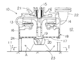
水中ポンプ10は、内部に回転自在にインペラ13が配設されているインペラケーシング14と、インペラケーシング14の上部に載置され、その出力軸15の先部にインペラ13が固着されている図示しない駆動モータと、インペラケーシング14の下部に連設され多孔筒部16と多孔底板17とからなる筒状ストレーナ18と、筒状ストレーナ18の多孔底板17の中央部に設けられた貫通孔19を通して下方に突出される出力軸15の突出先部に固着される攪拌体20とを具備する。なお、21は駆動モータを水密状態に囲繞するモータケーシング、22はインペラケーシング14の周壁の一部に設けられた開口部に連通連結された濁水配管である。
【0017】
本実施の形態に係る水中ポンプ10は、前記した基本構成に、さらに、図1及び図2に示すように、攪拌体20の直下に、攪拌体20の回転によって生じる下方向攪拌流Aによる土砂等の掘削を防止するための掘削防止板23が配設されていることを特徴とする。
【0018】
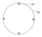
即ち、図1及び図2に示すように、筒状ストレーナ18の下部周縁には複数の支持脚24の上端が取り付けられており、これらの支持脚24の下端は、筒状ストレーナ18の直下方に配設された掘削防止板23の周縁部に、一体的、又は着脱自在に連結されている。
【0019】
図示するように、掘削防止板23は、筒状ストレーナ18の多孔底板17と略同一形状及び同一寸法を有しており、また、従来と異なり、全面にわたって閉塞又は盲板状態になっている。
【0020】
以下、前記した構成を有する水中ポンプ10の作動、特に、掘削防止板23の作動について説明する。
【0021】
駆動モータを回転することによって、インペラ13と攪拌体20とは一体的に回転されることになる。
この際、攪拌体20の回転によって、水中ポンプ10が設置されている溝11の設置面に向けて流れる下方向攪拌流Aが発生することになるが、攪拌体20の直下には、筒状ストレーナ18の多孔底板17と略等しい面積を有する掘削防止板23が配設されているので、下方向攪拌流Aは掘削防止板23に衝突し、その後、反射されて外部に放射状に流出することになる。
【0022】
従って、攪拌体20によって、水中ポンプ10が設置されている場所の土が下方向攪拌流Aによってを掘削されることがなくなり掘削された場合に生じる濁水12の高濃度化に起因するインペラ13やインペラケーシング14の摩耗を可及的に防止することができ、水中ポンプ10やその部品の長寿命化を図ることができると共に、メンテナンスも容易にすることができる。
【0023】
図3及び図4に、前記した掘削防止板23の幾つかの変容例を示す。
図3に示すように、第1の変容例に係る掘削防止板23Aは、下方向攪拌流Aを発生するための攪拌体として、直筒の外周面にプロペラを取り付けた攪拌体を用いた場合に好適に使用できるものである。
【0024】
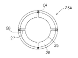
即ち、この場合、攪拌体は、プロペラの回転によって攪拌体の直下に向けて流れる下方向攪拌流を発生することになる。従って、掘削防止板23Aは、平板の中央部に、この下方向攪拌流を受けるために必要十分な面積を有する中央閉塞部25を形成すると共に、その中央閉塞部25の周りに周縁開口部26が設けられている。
【0025】
この周縁開口部26は、筒状ストレーナ18の投影面積に対して10%〜50%の割合の面積を有する。なお、掘削防止板23Aの中央閉塞部25は、連結リブ27と連結環28を介して筒状ストレーナ18に連結される。周縁開口部26の割合を10%〜50%としたのは、10%より小さい場合は、掘削防止板23Aの軽量化を図ることができず、一方、50%より大きくした場合は、水中ポンプ10の設置場所における土を掘削するおそれがあるからである。
【0026】
この場合においても、攪拌体20の下方向攪拌流Aが掘削防止板23Aの中央部のみに向けて流れる場合は、効果的に、下方向攪拌流Aは中央閉塞部25に衝突し、その後、反射されて放射状に流出することになる。
従って、水中ポンプ10が設置されている場所の土が下方向攪拌流Aによって掘削されることがなくなり掘削された場合に生じる濁水12の高濃度化に起因するインペラ13やインペラケーシング14の摩耗を可及的に防止することができ、水中ポンプ10やその部品の長寿命化を図ることができると共に、メンテナンスも容易にすることができる。
【0027】
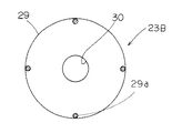
図4に示すように、第2の変容例に係る掘削防止板23Bは、下方向攪拌流Aを発生するための攪拌体として、下方に向けて漸次直径を小さくするテーパ部の外周面に攪拌羽根が取り付けられ、かつ、テーパ部の傾斜角度が比較的緩やかな攪拌体を用いた場合に好適に使用できるものである。
【0028】
即ち、この場合、攪拌体は、攪拌体の回転によって筒状ストレーナ18の外周部に向けて下方向攪拌流を発生することになる。従って、掘削防止板23Bは、平板の中央部に中央開口部30が形成されると共に、中央開口部30の周りに環状円板からなる周縁閉塞部29が形成されている。そして、中央開口部30の面積は、掘削防止板23Bを構成する平板全体の面積の10%〜50%を占めるようにしている。中央開口部30の面積を平板全体の面積の10%〜50%としたのは、10%より小さい場合は、掘削防止板の軽量化を図ることができず、一方、50%より大きくした場合は、水中ポンプ10の設置場所における土を掘削するおそれがあるからである。
【0029】
この場合においても、攪拌体20の下方向攪拌流Aが、特に掘削防止板23Bの周縁閉塞部29に向けて流れる場合は、下方向攪拌流Aは周縁閉塞部29に衝突し、その後、反射されて放射状に流出することになる。
従って、水中ポンプ10が設置されている場所の土が下方向攪拌流Aによって掘削されることがなくなり掘削された場合に生じる濁水12の高濃度化に起因するインペラ13やインペラケーシング14の摩耗を可及的に防止することができ、水中ポンプ10やその部品の長寿命化を図ることができると共に、メンテナンスも容易にすることができる。
なお、図4において、29aは支持脚である。
【0030】
(第2の実施の形態)
本実施の形態に係る水中ポンプ10Aは、図5に示すように、第1の実施の形態の構成に加えて、攪拌体31の上部と下部に、それぞれ、筒状ストレーナ18の目詰まりを防止するための水平方向流発生部32と、濁水12中の土砂の沈殿を防止するための下方向攪拌流発生部33とが形成されることを特徴とする。なお、攪拌体31を除いて、本実施の形態に係る水中ポンプ10Aは、図1に示す第1の実施の形態に係る水中ポンプ10と同一の構成を有するので、同一の構成要素は同一の符号で示す。
【0031】
図5に示すように、本実施の形態では、攪拌体31の本体を形成する羽根取付軸は、全高にわたって同一直径を有する直筒部34と、この直筒部34の下部に一体的に連設され下方に向けて漸次直径を小さくするテーパ部35とからなる。そして、直筒部34の外周面には、円周方向に間隔を開けて、矩形板からなる複数の水平方向流発生羽根36が、羽根取付軸の軸線と平行に取り付けられており、テーパ部35の外周面には、円周方向に間隔を開けて複数の楕円状の下方向攪拌流発生羽根37が、羽根取付軸の軸線に対して所定のねじり角度をもって取り付けられている。
【0032】
前記構成において、直筒部34と水平方向流発生羽根36とによって水平方向流発生部32が形成される。そして、この水平方向流発生部32を回転すると、複数の水平方向流発生羽根36は、直筒部34に、羽根取付軸の軸線と平行に取り付けられているので、濁水12は、水中ポンプ10Aが設置されている溝11の設置面と略平行に流れることになる。即ち、水平方向流発生部32の回転によって水平方向流Bが容易に発生されることになる。
【0033】
一方、テーパ部35と下方向攪拌流発生羽根37とによって下方向攪拌流発生部33が形成される。そして、この下方向攪拌流発生部33を回転すると、複数の下方向攪拌流発生羽根37は、テーパ部35に、羽根取付軸の軸線に対して所定のねじり角度をもって取り付けられているので、濁水12は、水中ポンプ10Aが設置されている溝11の設置面に向けて流れることになる。即ち、下方向攪拌流発生部33の回転によって下方向攪拌流Cが容易に発生されることになる。
【0034】
以下、上記した構成を有する水中ポンプ10Aの作動、特に、攪拌体31の作動について説明する。
【0035】
駆動モータを回転することによって、インペラ13と、水平方向流発生部32と下方向攪拌流発生部33とを具備する攪拌体31とを一体的に回転されることになる。
この際、攪拌体31の回転によって、水中ポンプ10Aが設置されている溝11の設置面に向けて流れる下方向攪拌流Cが発生することになるが、攪拌体31の直下には、筒状ストレーナ18の多孔底板17と略等しい面積を有する掘削防止板23が配設されているので、下方向攪拌流Cは掘削防止板23に衝突し、その後、反射されて外部に放射状に流出することになる。
【0036】
従って、攪拌体31によって、水中ポンプ10Aが設置されている場所の周縁の部の土が下方向攪拌流Cによってを掘削されることがなくなり掘削された場合に生じる濁水12の高濃度化に起因するインペラ13やインペラケーシング14の摩耗を可及的に防止することができ、水中ポンプ10Aやその部品の長寿命化を図ることができると共に、メンテナンスも容易にすることができる。
【0037】
また、本実施の形態では、下方向攪拌流Cは、攪拌体31の全体ではなく、その一部をなす下方向攪拌流発生部33の回転によって発生するようにしているので、溝11の設置面上に濁水12中の泥等が沈殿するのを防止するために必要十分な水勢しか発生しない。
【0038】
また、前述したように、水平方向流発生部32の回転によって、水中ポンプ10Aが設置されている溝11の設置面と略平行に流れる水平方向流Bが発生されることになるため、濁水12中に木の葉等が混入されている場合であっても、木の葉等が筒状ストレーナ18の多孔筒部16や多孔底板17に吸着されるのを効果的に防止することができ、常時、水中ポンプ10Aの良好な排水効率を維持することができ、安定した排水作業を行うことができる。
【0039】
【発明の効果】
請求項1〜3記載の攪拌抑制機能を有する水中ポンプにおいては、インペラケーシングの下部に多孔筒部と多孔底板とからなる筒状ストレーナを一体的に連設し、インペラケーシングの上部に連設された駆動モータの出力軸が、筒状ストレーナの多孔底板の中央部に設けられた貫通孔を通して下方に突出され、突出先部に攪拌体が固着されている水中ポンプにおいて、攪拌体の直下に、攪拌体の回転によって生じる下方向攪拌流による土砂等の掘削を防止するための掘削防止板が配設されている。
【0040】
従って、攪拌体の回転によって生じる下方向攪拌流は掘削防止板に衝突することになるので、水中ポンプが設置されている場所の土が下方向攪拌流によって掘削されることがなくなり、掘削された場合に生じる濁水の高濃度化に起因するインペラやインペラケーシングの摩耗を可及的に防止することができ、水中ポンプやその部品の長寿命化を図ることができると共に、メンテナンスも容易にすることができる。
そして、請求項1記載の攪拌抑制機能を有する水中ポンプにおいては、攪拌体の上部と下部に、それぞれ、筒状ストレーナの目詰まりを防止するための水平方向流発生部と、濁水中の土砂の沈殿を防止するための下方向攪拌流発生部とが形成されている。
従って、水中ポンプが設置されている場所のみならず、その周縁部における土も掘削するおそれがなくなり、周縁の部の土を掘削された場合に生じる濁水の高濃度化に起因するイ ンペラやインペラケーシングの摩耗を可及的に防止することができ、水中ポンプやその部品の長寿命化を図ることができると共に、メンテナンスも容易にすることができる。
また、水平方向流発生部の回転によって水平方向流が発生されることになるため、濁水中に木の葉等が混入されている場合であっても、木の葉等が筒状ストレーナの多孔筒部や多孔底板に吸着されるのを効果的に防止することができ、常時、水中ポンプの良好な排水効率を維持することができ、安定した排水作業を行うことができる。
【0041】
特に、請求項2記載の攪拌抑制機能を有する水中ポンプにおいては、掘削防止板を形成する平板は、中央閉塞部の周りに周縁開口部が設けられており、周縁開口部は、筒状ストレーナの投影面積に対して10%〜50%の割合の面積を有するようにしている。
従って、特に攪拌体として攪拌体の直下に向けて流れる下方向攪拌流を発生する攪拌体を用いた場合において、掘削防止板の軽量化を図りつつ、下方向攪拌流による水中ポンプ設置場所における土の掘削を効果的に防止することができる。
【0042】
請求項3記載の攪拌抑制機能を有する水中ポンプにおいては、掘削防止板を形成する平板の中央部には中央開口部が設けられており、この中央開口部は、平板全体の面積の10%〜50%を占めるようにしている。
従って、特に攪拌体として、下方に向けて漸次直径を小さくするテーパ部の外周面に攪拌羽根が取り付けられ、かつ、テーパ部の傾斜角度が比較的緩やかな攪拌体を用いた場合において、掘削防止板の軽量化を図りつつ、下方向攪拌流による水中ポンプ設置場所における土の掘削を効果的に防止することができる。
【0043】
【0044】
【図面の簡単な説明】
【図1】本発明の第1の実施の形態に係る攪拌抑制機能を有する水中ポンプの一部切欠正面図である。
【図2】図1のI−I矢視図である。
【図3】掘削防止板の第1の変容例の説明図である。
【図4】掘削防止板の第2の変容例の説明図である。
【図5】本発明の第2の実施の形態に係る攪拌抑制機能を有する水中ポンプの一部切欠正面図である。
【図6】従来の水中ポンプの使用状態の説明図である。
【図7】同正断面図である。
【図8】同底面図である。
【図9】同他の底面図である。
【符号の説明】
A 下方向攪拌流 B 水平方向流
C 下方向攪拌流 10 水中ポンプ
10A 水中ポンプ 11 溝
12 濁水 13 インペラ
14 インペラケーシング 15 出力軸
16 多孔筒部 17 多孔底板
18 筒状ストレーナ 19 貫通孔
20 攪拌体 21 モータケーシング
22 濁水配管 23 掘削防止板
23A 掘削防止板 23B 掘削防止板
24 支持脚 25 中央閉塞部
26 周縁開口部 27 連結リブ
28 連結環 29 周縁閉塞部
29a 支持脚 30 中央開口部
31 攪拌体 32 水平方向流発生部
33 下方向攪拌流発生部 34 直筒部
35 テーパ部 36 水平方向流発生羽根
37 下方向攪拌流発生羽根[0001]
TECHNICAL FIELD OF THE INVENTION
The present invention relates to a submersible pump having an agitation suppressing function capable of effectively draining turbid water flowing into various grooves and holes in civil engineering and construction sites. Here, the turbid water refers to rainwater containing mud, mud generated by using water in civil engineering and construction work, water containing bentonite, and the like.
[0002]
[Prior art]
In the above-mentioned civil engineering / building site, for example, turbid water flows into trenches and holes that have been excavated in advance for concrete foundation work. Can not be done. Therefore, as shown in FIG. 6, the
[0003]
That is, as shown in FIG. 6 and FIG. 7, the
[0004]
Then, by rotating the
[0005]
[Problems to be solved by the invention]
However, the above-described conventional
That is, as shown in FIG. 6 and FIG. 7, the
On the other hand, when mounting the
[0006]
Accordingly, in such a discharging operation of the
[0007]
In addition, when leaves and the like are mixed in the
[0008]
The present invention has been made in view of such circumstances, and relates to a submersible pump having an agitation suppressing function capable of effectively draining turbid water flowing into various grooves and holes in civil engineering and construction sites.
[0009]
[Means for Solving the Problems]
A submersible pump having an agitation suppressing function according to claim 1, which is in line with the object, has a tubular strainer composed of a porous tubular portion and a porous bottom plate integrally connected to a lower portion of the impeller casing, and is connected to an upper portion of the impeller casing. In the submersible pump, the output shaft of the provided drive motor is projected downward through a through hole provided at the center of the porous bottom plate of the cylindrical strainer, and the stirrer is fixed to the projected end.
The stirring member is arranged below the perforated bottom plate, moreover, the horizontal flow onset raw wings respectively provided downward agitating flow generating vanes in the lower portion to the upper portion of the stirring body, prevent clogging of the tubular strainer A horizontal flow generation part for squeezing, and a downward stirring flow generation part for preventing sedimentation of mud in muddy water are formed,
Further, an excavation prevention plate for preventing excavation of earth and sand or the like by a downward stirring flow generated by rotation of the agitator is provided immediately below the agitator.
[0010]
A submersible pump having a stirring suppression function according to
Immediately below the stirrer, an excavation prevention plate for preventing excavation of earth and sand due to downward stirring flow generated by rotation of the stirrer is provided, and the flat plate forming the excavation prevention plate has a central obstruction. A peripheral opening is provided around the portion, and the peripheral opening has an area of 10% to 50% of the projected area of the cylindrical strainer.
[0011]
A submersible pump having a stirring suppression function according to claim 3 , wherein a cylindrical strainer composed of a porous tubular portion and a porous bottom plate is integrally connected to a lower portion of the impeller casing, and a drive connected to an upper portion of the impeller casing. In a submersible pump in which an output shaft of a motor is projected downward through a through hole provided in a central portion of a porous bottom plate of the cylindrical strainer, and a stirrer is fixed to a projected end portion,
Immediately below the stirrer, an excavation prevention plate for preventing excavation of soil and the like due to downward stirring flow generated by rotation of the stirrer is provided, and at the center of the flat plate forming the excavation prevention plate. Is provided with a central opening, and the
[0012]
[0013]
BEST MODE FOR CARRYING OUT THE INVENTION
Next, some embodiments embodying the present invention will be described with reference to the attached drawings to provide an understanding of the present invention.
[0014]
(First Embodiment)
The basic configuration of a submersible pump having a stirring suppression function according to a first embodiment of the present invention will be described with reference to FIG.
[0015]
As shown in FIG. 1, the
[0016]
The
[0017]
The
[0018]
That is, as shown in FIGS. 1 and 2, the upper ends of a plurality of
[0019]
As shown in the drawing, the
[0020]
Hereinafter, the operation of the
[0021]
By rotating the drive motor, the
At this time, rotation of the stirrer 20 generates a downward stirring flow A flowing toward the installation surface of the groove 11 in which the
[0022]
Accordingly, the agitator 20 prevents the soil at the place where the
[0023]
3 and 4 show some modifications of the above-described
As shown in FIG. 3, the
[0024]
That is, in this case, the stirring body generates a downward stirring flow flowing directly below the stirring body by the rotation of the propeller. Therefore, the
[0025]
The
[0026]
Also in this case, when the downward stirring flow A of the stirring body 20 flows only toward the central portion of the
Therefore, the soil at the place where the
[0027]
As shown in FIG. 4, the
[0028]
That is, in this case, the stirring body generates a downward stirring flow toward the outer peripheral portion of the
[0029]
Also in this case, when the downward stirring flow A of the stirrer 20 flows particularly toward the
Therefore, the soil at the place where the
In FIG. 4,
[0030]
(Second embodiment)
As shown in FIG. 5, the submersible pump 10A according to the present embodiment, in addition to the configuration of the first embodiment, prevents the
[0031]
As shown in FIG. 5, in the present embodiment, the blade mounting shaft forming the main body of the stirring
[0032]
In the above configuration, the horizontal
[0033]
On the other hand, the downward stirring
[0034]
Hereinafter, the operation of the submersible pump 10A having the above-described configuration, particularly, the operation of the stirring
[0035]
By rotating the drive motor, the
At this time, the rotation of the
[0036]
Accordingly, the
[0037]
Further, in the present embodiment, the downward stirring flow C is generated not by the whole of the stirring
[0038]
In addition, as described above, the rotation of the horizontal
[0039]
【The invention's effect】
In the submersible pump having the stirring suppression function according to claims 1 to 3 , a cylindrical strainer including a porous cylindrical portion and a porous bottom plate is integrally connected to a lower portion of the impeller casing, and is connected to an upper portion of the impeller casing. The output shaft of the drive motor is projected downward through a through-hole provided in the center of the porous bottom plate of the cylindrical strainer, and in a submersible pump in which the stirrer is fixed to the protruding portion, immediately below the stirrer, An excavation prevention plate for preventing excavation of earth and sand or the like due to downward stirring flow generated by rotation of the stirrer is provided.
[0040]
Therefore, since the downward stirring flow generated by the rotation of the stirring body collides with the excavation prevention plate, the soil at the place where the submersible pump is installed is not excavated by the downward stirring flow, and the excavation is performed. The wear of the impeller and the impeller casing due to the high concentration of turbid water generated in the case can be prevented as much as possible, and the service life of the submersible pump and its components can be extended, and the maintenance is also easy. Can be.
In the submersible pump having the stirring suppression function according to the first aspect, a horizontal flow generating section for preventing clogging of the cylindrical strainer is provided at an upper portion and a lower portion of the stirring body, respectively, and A downward stirring flow generating portion for preventing sedimentation is formed.
Therefore, not only the location submersible pump is installed, Lee Npera and impeller due to the high concentration of turbid water there is no possibility that also excavated soil at the periphery occurs when excavated soil parts of the peripheral edge Wear of the casing can be prevented as much as possible, the service life of the submersible pump and its components can be extended, and maintenance can be facilitated.
In addition, since the horizontal flow is generated by the rotation of the horizontal flow generation part, even when the leaves and the like are mixed in the muddy water, the leaves and the like are not affected by the perforated cylindrical portion of the cylindrical strainer or the perforated tube. Adsorption to the bottom plate can be effectively prevented, good drainage efficiency of the submersible pump can be constantly maintained, and stable drainage work can be performed.
[0041]
In particular, in the submersible pump having the agitation suppressing function according to
Therefore, particularly when a stirrer that generates a downward stirring flow flowing directly below the stirrer is used as the stirrer, the soil at the location of the submersible pump by the downward stirring flow is reduced while the weight of the anti-digging plate is reduced. Excavation can be effectively prevented.
[0042]
In the submersible pump having the stirring suppression function according to the third aspect, a central opening is provided at the center of the flat plate forming the excavation prevention plate, and the central opening is 10% to 10% of the area of the entire flat plate. It occupies 50%.
Therefore, especially when a stirring member is attached to the outer peripheral surface of the tapered portion whose diameter gradually decreases downward as the stirring member and the inclination angle of the tapered portion is relatively gentle, the excavation is prevented. It is possible to effectively prevent excavation of soil at the submersible pump installation site due to downward stirring flow while reducing the weight of the plate.
[0043]
[0044]
[Brief description of the drawings]
FIG. 1 is a partially cutaway front view of a submersible pump having a stirring suppression function according to a first embodiment of the present invention.
FIG. 2 is a view taken in the direction of an arrow II in FIG. 1;
FIG. 3 is an explanatory diagram of a first modification of the excavation prevention plate.
FIG. 4 is an explanatory view of a second modification of the excavation prevention plate.
FIG. 5 is a partially cutaway front view of a submersible pump having a stirring suppression function according to a second embodiment of the present invention.
FIG. 6 is an explanatory diagram of a use state of a conventional submersible pump.
FIG. 7 is a front sectional view of the same.
FIG. 8 is a bottom view of the same.
FIG. 9 is another bottom view.
[Explanation of symbols]
Reference Signs List A Downward stirring flow B Horizontal flow C Downward stirring
Claims (3)
前記攪拌体が前記多孔底板の下方に配置され、しかも、前記攪拌体の上部に水平方向流発生羽根を下部に下方向攪拌流発生羽根をそれぞれ設けて、前記筒状ストレーナの目詰まりを防止するめための水平方向流発生部と、濁水中の泥の沈殿を防止するための下方向攪拌流発生部とが形成され、
更に、前記攪拌体の直下に、該攪拌体の回転によって生じる下方向攪拌流による土砂等の掘削を防止するための掘削防止板が配設されていることを特徴とする攪拌抑制機能を有する水中ポンプ。A cylindrical strainer composed of a perforated tubular portion and a perforated bottom plate is integrally connected to a lower portion of the impeller casing, and an output shaft of a drive motor connected to an upper portion of the impeller casing is connected to a perforated bottom plate of the cylindrical strainer. In a submersible pump that protrudes downward through a through hole provided in a central portion and a stirrer is fixed to a protruding portion,
The stirrer is disposed below the perforated bottom plate, and a horizontal flow generating blade is provided above the stirrer and a downward stirring flow generating blade is provided below the stirrer to prevent clogging of the cylindrical strainer. A horizontal flow generator for forming a downward agitated flow generator to prevent sedimentation of mud in muddy water is formed,
Furthermore, an excavation prevention plate for preventing excavation of soil and the like due to a downward stirring flow generated by rotation of the agitator is provided immediately below the agitator, and the underwater having an agitation suppressing function is provided. pump.
前記攪拌体の直下に、該攪拌体の回転によって生じる下方向攪拌流による土砂等の掘削を防止するための掘削防止板が配設され、しかも、前記掘削防止板を形成する平板は、中央閉塞部の周りに周縁開口部が設けられており、該周縁開口部は、前記筒状ストレーナの投影面積に対して10%〜50%の割合の面積を有することを特徴とする攪拌抑制機能を有する水中ポンプ。 A cylindrical strainer composed of a perforated tubular portion and a perforated bottom plate is integrally connected to a lower portion of the impeller casing, and an output shaft of a drive motor connected to an upper portion of the impeller casing is connected to a perforated bottom plate of the cylindrical strainer. In a submersible pump that is projected downward through a through hole provided in a central portion, and a stirrer is fixed to a projected portion,
Immediately below the stirrer, an excavation prevention plate for preventing excavation of earth and sand due to downward stirring flow generated by rotation of the stirrer is provided, and the flat plate forming the excavation prevention plate has a central obstruction. A peripheral opening is provided around the portion, and the peripheral opening has an area of 10% to 50% of the projected area of the cylindrical strainer, and has a stirring suppression function. underwater pump.
前記攪拌体の直下に、該攪拌体の回転によって生じる下方向攪拌流による土砂等の掘削を防止するための掘削防止板が配設され、しかも、前記掘削防止板を形成する平板の中央部には中央開口部が設けられており、該中央開口部は、前記平板全体の面積の10%〜50%を占めることを特徴とする攪拌抑制機能を有する水中ポンプ。 A cylindrical strainer composed of a perforated tubular portion and a perforated bottom plate is integrally connected to a lower portion of the impeller casing, and an output shaft of a drive motor connected to an upper portion of the impeller casing is connected to a perforated bottom plate of the cylindrical strainer. In a submersible pump that protrudes downward through a through hole provided in a central portion and a stirrer is fixed to a protruding portion,
Immediately below the stirrer, an excavation prevention plate for preventing excavation of soil and the like due to downward stirring flow generated by rotation of the stirrer is provided, and at the center of the flat plate forming the excavation prevention plate. Is provided with a central opening, and the central opening occupies 10% to 50% of the area of the entire flat plate, wherein the submersible pump has a stirring suppression function.
Priority Applications (1)
| Application Number | Priority Date | Filing Date | Title |
|---|---|---|---|
| JP17850096A JP3554635B2 (en) | 1996-06-18 | 1996-06-18 | Submersible pump with stirring suppression function |
Applications Claiming Priority (1)
| Application Number | Priority Date | Filing Date | Title |
|---|---|---|---|
| JP17850096A JP3554635B2 (en) | 1996-06-18 | 1996-06-18 | Submersible pump with stirring suppression function |
Publications (2)
| Publication Number | Publication Date |
|---|---|
| JPH109182A JPH109182A (en) | 1998-01-13 |
| JP3554635B2 true JP3554635B2 (en) | 2004-08-18 |
Family
ID=16049556
Family Applications (1)
| Application Number | Title | Priority Date | Filing Date |
|---|---|---|---|
| JP17850096A Expired - Fee Related JP3554635B2 (en) | 1996-06-18 | 1996-06-18 | Submersible pump with stirring suppression function |
Country Status (1)
| Country | Link |
|---|---|
| JP (1) | JP3554635B2 (en) |
Families Citing this family (6)
| Publication number | Priority date | Publication date | Assignee | Title |
|---|---|---|---|---|
| JP3672505B2 (en) * | 2001-06-19 | 2005-07-20 | 株式会社東洋電機工業所 | Submersible agitation pump |
| JP2006090134A (en) * | 2004-09-21 | 2006-04-06 | Toyo Denki Industrial Co Ltd | Vertical submerged pump having agitating blade |
| JP5563365B2 (en) * | 2010-05-11 | 2014-07-30 | 株式会社東洋電機工業所 | Agitator for submersible pump and submersible pump using the same |
| JP6099505B2 (en) * | 2013-07-01 | 2017-03-22 | 株式会社鶴見製作所 | Portable submersible electric pump equipped with stirring blades |
| CN108980053A (en) * | 2018-09-19 | 2018-12-11 | 中冶北方(大连)工程技术有限公司 | Ore dressing station-service sewage pump |
| CN113648872B (en) * | 2021-08-20 | 2024-01-16 | 浙江起航环境集团有限公司 | An efficient hyperboloid mixer |
-
1996
- 1996-06-18 JP JP17850096A patent/JP3554635B2/en not_active Expired - Fee Related
Also Published As
| Publication number | Publication date |
|---|---|
| JPH109182A (en) | 1998-01-13 |
Similar Documents
| Publication | Publication Date | Title |
|---|---|---|
| AU785215B2 (en) | Gravel-or-the-like removing device | |
| JP3554635B2 (en) | Submersible pump with stirring suppression function | |
| JP3554634B2 (en) | Submersible pump capable of generating two-way flow | |
| JP3672505B2 (en) | Submersible agitation pump | |
| JP5618392B1 (en) | Fluid stirring device and sand pump using the same | |
| JP4601047B2 (en) | Disturbance pump | |
| CN208965621U (en) | A water conservancy project dredging device | |
| JP2009035948A (en) | Underwater sediment stirrer | |
| JPH11350529A (en) | Drilling shear receiving and pumping equipment for drilling equipment | |
| JP4301429B2 (en) | Submersible agitation pump | |
| JP2013092074A (en) | Agitator for submerged pump | |
| US20230374751A1 (en) | Dredge system | |
| CN215629966U (en) | Slag removing device for ultra-deep cast-in-situ bored pile | |
| KR101637409B1 (en) | Environment dredger | |
| JP3926777B2 (en) | Mud suction device | |
| JP4726184B2 (en) | Disturbance pump | |
| CN115262601B (en) | Island muddy soil dewatering and dewatering system and its dewatering and dewatering method | |
| JP4839974B2 (en) | Resin submersible pump | |
| JP2528565B2 (en) | Method and equipment for slime treatment of bottom drilling | |
| JP2704396B2 (en) | Underwater drilling method using underwater sand pump and underwater sand pump | |
| JP5563365B2 (en) | Agitator for submersible pump and submersible pump using the same | |
| JPH0634637Y2 (en) | Submersible pump with stirring flow control ring | |
| CN208815602U (en) | A kind of hydraulic engineering dredging dredger | |
| JPH0624416Y2 (en) | Auger used to form the soil mountain stop wall | |
| JPH0113832Y2 (en) |
Legal Events
| Date | Code | Title | Description |
|---|---|---|---|
| A521 | Written amendment |
Free format text: JAPANESE INTERMEDIATE CODE: A523 Effective date: 20040210 |
|
| TRDD | Decision of grant or rejection written | ||
| A01 | Written decision to grant a patent or to grant a registration (utility model) |
Free format text: JAPANESE INTERMEDIATE CODE: A01 Effective date: 20040413 |
|
| A61 | First payment of annual fees (during grant procedure) |
Free format text: JAPANESE INTERMEDIATE CODE: A61 Effective date: 20040510 |
|
| R150 | Certificate of patent or registration of utility model |
Free format text: JAPANESE INTERMEDIATE CODE: R150 |
|
| R250 | Receipt of annual fees |
Free format text: JAPANESE INTERMEDIATE CODE: R250 |
|
| FPAY | Renewal fee payment (event date is renewal date of database) |
Free format text: PAYMENT UNTIL: 20090514 Year of fee payment: 5 |
|
| FPAY | Renewal fee payment (event date is renewal date of database) |
Free format text: PAYMENT UNTIL: 20090514 Year of fee payment: 5 |
|
| FPAY | Renewal fee payment (event date is renewal date of database) |
Free format text: PAYMENT UNTIL: 20100514 Year of fee payment: 6 |
|
| FPAY | Renewal fee payment (event date is renewal date of database) |
Free format text: PAYMENT UNTIL: 20110514 Year of fee payment: 7 |
|
| FPAY | Renewal fee payment (event date is renewal date of database) |
Free format text: PAYMENT UNTIL: 20120514 Year of fee payment: 8 |
|
| FPAY | Renewal fee payment (event date is renewal date of database) |
Free format text: PAYMENT UNTIL: 20130514 Year of fee payment: 9 |
|
| R250 | Receipt of annual fees |
Free format text: JAPANESE INTERMEDIATE CODE: R250 |
|
| LAPS | Cancellation because of no payment of annual fees |