EP1270301A2 - Power transmission apparatus for automobile - Google Patents
Power transmission apparatus for automobile Download PDFInfo
- Publication number
- EP1270301A2 EP1270301A2 EP02002038A EP02002038A EP1270301A2 EP 1270301 A2 EP1270301 A2 EP 1270301A2 EP 02002038 A EP02002038 A EP 02002038A EP 02002038 A EP02002038 A EP 02002038A EP 1270301 A2 EP1270301 A2 EP 1270301A2
- Authority
- EP
- European Patent Office
- Prior art keywords
- motor
- gear
- input shaft
- engine
- torque
- Prior art date
- Legal status (The legal status is an assumption and is not a legal conclusion. Google has not performed a legal analysis and makes no representation as to the accuracy of the status listed.)
- Withdrawn
Links
Images









Classifications
-
- B—PERFORMING OPERATIONS; TRANSPORTING
- B60—VEHICLES IN GENERAL
- B60K—ARRANGEMENT OR MOUNTING OF PROPULSION UNITS OR OF TRANSMISSIONS IN VEHICLES; ARRANGEMENT OR MOUNTING OF PLURAL DIVERSE PRIME-MOVERS IN VEHICLES; AUXILIARY DRIVES FOR VEHICLES; INSTRUMENTATION OR DASHBOARDS FOR VEHICLES; ARRANGEMENTS IN CONNECTION WITH COOLING, AIR INTAKE, GAS EXHAUST OR FUEL SUPPLY OF PROPULSION UNITS IN VEHICLES
- B60K6/00—Arrangement or mounting of plural diverse prime-movers for mutual or common propulsion, e.g. hybrid propulsion systems comprising electric motors and internal combustion engines
- B60K6/20—Arrangement or mounting of plural diverse prime-movers for mutual or common propulsion, e.g. hybrid propulsion systems comprising electric motors and internal combustion engines the prime-movers consisting of electric motors and internal combustion engines, e.g. HEVs
- B60K6/22—Arrangement or mounting of plural diverse prime-movers for mutual or common propulsion, e.g. hybrid propulsion systems comprising electric motors and internal combustion engines the prime-movers consisting of electric motors and internal combustion engines, e.g. HEVs characterised by apparatus, components or means specially adapted for HEVs
- B60K6/38—Arrangement or mounting of plural diverse prime-movers for mutual or common propulsion, e.g. hybrid propulsion systems comprising electric motors and internal combustion engines the prime-movers consisting of electric motors and internal combustion engines, e.g. HEVs characterised by apparatus, components or means specially adapted for HEVs characterised by the driveline clutches
-
- B—PERFORMING OPERATIONS; TRANSPORTING
- B60—VEHICLES IN GENERAL
- B60K—ARRANGEMENT OR MOUNTING OF PROPULSION UNITS OR OF TRANSMISSIONS IN VEHICLES; ARRANGEMENT OR MOUNTING OF PLURAL DIVERSE PRIME-MOVERS IN VEHICLES; AUXILIARY DRIVES FOR VEHICLES; INSTRUMENTATION OR DASHBOARDS FOR VEHICLES; ARRANGEMENTS IN CONNECTION WITH COOLING, AIR INTAKE, GAS EXHAUST OR FUEL SUPPLY OF PROPULSION UNITS IN VEHICLES
- B60K6/00—Arrangement or mounting of plural diverse prime-movers for mutual or common propulsion, e.g. hybrid propulsion systems comprising electric motors and internal combustion engines
- B60K6/20—Arrangement or mounting of plural diverse prime-movers for mutual or common propulsion, e.g. hybrid propulsion systems comprising electric motors and internal combustion engines the prime-movers consisting of electric motors and internal combustion engines, e.g. HEVs
- B60K6/42—Arrangement or mounting of plural diverse prime-movers for mutual or common propulsion, e.g. hybrid propulsion systems comprising electric motors and internal combustion engines the prime-movers consisting of electric motors and internal combustion engines, e.g. HEVs characterised by the architecture of the hybrid electric vehicle
- B60K6/44—Series-parallel type
- B60K6/442—Series-parallel switching type
-
- B—PERFORMING OPERATIONS; TRANSPORTING
- B60—VEHICLES IN GENERAL
- B60K—ARRANGEMENT OR MOUNTING OF PROPULSION UNITS OR OF TRANSMISSIONS IN VEHICLES; ARRANGEMENT OR MOUNTING OF PLURAL DIVERSE PRIME-MOVERS IN VEHICLES; AUXILIARY DRIVES FOR VEHICLES; INSTRUMENTATION OR DASHBOARDS FOR VEHICLES; ARRANGEMENTS IN CONNECTION WITH COOLING, AIR INTAKE, GAS EXHAUST OR FUEL SUPPLY OF PROPULSION UNITS IN VEHICLES
- B60K6/00—Arrangement or mounting of plural diverse prime-movers for mutual or common propulsion, e.g. hybrid propulsion systems comprising electric motors and internal combustion engines
- B60K6/20—Arrangement or mounting of plural diverse prime-movers for mutual or common propulsion, e.g. hybrid propulsion systems comprising electric motors and internal combustion engines the prime-movers consisting of electric motors and internal combustion engines, e.g. HEVs
- B60K6/42—Arrangement or mounting of plural diverse prime-movers for mutual or common propulsion, e.g. hybrid propulsion systems comprising electric motors and internal combustion engines the prime-movers consisting of electric motors and internal combustion engines, e.g. HEVs characterised by the architecture of the hybrid electric vehicle
- B60K6/48—Parallel type
-
- B—PERFORMING OPERATIONS; TRANSPORTING
- B60—VEHICLES IN GENERAL
- B60K—ARRANGEMENT OR MOUNTING OF PROPULSION UNITS OR OF TRANSMISSIONS IN VEHICLES; ARRANGEMENT OR MOUNTING OF PLURAL DIVERSE PRIME-MOVERS IN VEHICLES; AUXILIARY DRIVES FOR VEHICLES; INSTRUMENTATION OR DASHBOARDS FOR VEHICLES; ARRANGEMENTS IN CONNECTION WITH COOLING, AIR INTAKE, GAS EXHAUST OR FUEL SUPPLY OF PROPULSION UNITS IN VEHICLES
- B60K6/00—Arrangement or mounting of plural diverse prime-movers for mutual or common propulsion, e.g. hybrid propulsion systems comprising electric motors and internal combustion engines
- B60K6/20—Arrangement or mounting of plural diverse prime-movers for mutual or common propulsion, e.g. hybrid propulsion systems comprising electric motors and internal combustion engines the prime-movers consisting of electric motors and internal combustion engines, e.g. HEVs
- B60K6/50—Architecture of the driveline characterised by arrangement or kind of transmission units
- B60K6/54—Transmission for changing ratio
- B60K6/547—Transmission for changing ratio the transmission being a stepped gearing
-
- B—PERFORMING OPERATIONS; TRANSPORTING
- B60—VEHICLES IN GENERAL
- B60W—CONJOINT CONTROL OF VEHICLE SUB-UNITS OF DIFFERENT TYPE OR DIFFERENT FUNCTION; CONTROL SYSTEMS SPECIALLY ADAPTED FOR HYBRID VEHICLES; ROAD VEHICLE DRIVE CONTROL SYSTEMS FOR PURPOSES NOT RELATED TO THE CONTROL OF A PARTICULAR SUB-UNIT
- B60W10/00—Conjoint control of vehicle sub-units of different type or different function
- B60W10/02—Conjoint control of vehicle sub-units of different type or different function including control of driveline clutches
-
- B—PERFORMING OPERATIONS; TRANSPORTING
- B60—VEHICLES IN GENERAL
- B60W—CONJOINT CONTROL OF VEHICLE SUB-UNITS OF DIFFERENT TYPE OR DIFFERENT FUNCTION; CONTROL SYSTEMS SPECIALLY ADAPTED FOR HYBRID VEHICLES; ROAD VEHICLE DRIVE CONTROL SYSTEMS FOR PURPOSES NOT RELATED TO THE CONTROL OF A PARTICULAR SUB-UNIT
- B60W10/00—Conjoint control of vehicle sub-units of different type or different function
- B60W10/04—Conjoint control of vehicle sub-units of different type or different function including control of propulsion units
- B60W10/06—Conjoint control of vehicle sub-units of different type or different function including control of propulsion units including control of combustion engines
-
- B—PERFORMING OPERATIONS; TRANSPORTING
- B60—VEHICLES IN GENERAL
- B60W—CONJOINT CONTROL OF VEHICLE SUB-UNITS OF DIFFERENT TYPE OR DIFFERENT FUNCTION; CONTROL SYSTEMS SPECIALLY ADAPTED FOR HYBRID VEHICLES; ROAD VEHICLE DRIVE CONTROL SYSTEMS FOR PURPOSES NOT RELATED TO THE CONTROL OF A PARTICULAR SUB-UNIT
- B60W10/00—Conjoint control of vehicle sub-units of different type or different function
- B60W10/10—Conjoint control of vehicle sub-units of different type or different function including control of change-speed gearings
-
- B—PERFORMING OPERATIONS; TRANSPORTING
- B60—VEHICLES IN GENERAL
- B60W—CONJOINT CONTROL OF VEHICLE SUB-UNITS OF DIFFERENT TYPE OR DIFFERENT FUNCTION; CONTROL SYSTEMS SPECIALLY ADAPTED FOR HYBRID VEHICLES; ROAD VEHICLE DRIVE CONTROL SYSTEMS FOR PURPOSES NOT RELATED TO THE CONTROL OF A PARTICULAR SUB-UNIT
- B60W10/00—Conjoint control of vehicle sub-units of different type or different function
- B60W10/10—Conjoint control of vehicle sub-units of different type or different function including control of change-speed gearings
- B60W10/11—Stepped gearings
-
- B—PERFORMING OPERATIONS; TRANSPORTING
- B60—VEHICLES IN GENERAL
- B60W—CONJOINT CONTROL OF VEHICLE SUB-UNITS OF DIFFERENT TYPE OR DIFFERENT FUNCTION; CONTROL SYSTEMS SPECIALLY ADAPTED FOR HYBRID VEHICLES; ROAD VEHICLE DRIVE CONTROL SYSTEMS FOR PURPOSES NOT RELATED TO THE CONTROL OF A PARTICULAR SUB-UNIT
- B60W10/00—Conjoint control of vehicle sub-units of different type or different function
- B60W10/10—Conjoint control of vehicle sub-units of different type or different function including control of change-speed gearings
- B60W10/11—Stepped gearings
- B60W10/113—Stepped gearings with two input flow paths, e.g. double clutch transmission selection of one of the torque flow paths by the corresponding input clutch
-
- B—PERFORMING OPERATIONS; TRANSPORTING
- B60—VEHICLES IN GENERAL
- B60W—CONJOINT CONTROL OF VEHICLE SUB-UNITS OF DIFFERENT TYPE OR DIFFERENT FUNCTION; CONTROL SYSTEMS SPECIALLY ADAPTED FOR HYBRID VEHICLES; ROAD VEHICLE DRIVE CONTROL SYSTEMS FOR PURPOSES NOT RELATED TO THE CONTROL OF A PARTICULAR SUB-UNIT
- B60W30/00—Purposes of road vehicle drive control systems not related to the control of a particular sub-unit, e.g. of systems using conjoint control of vehicle sub-units
- B60W30/18—Propelling the vehicle
- B60W30/18009—Propelling the vehicle related to particular drive situations
- B60W30/18063—Creeping
-
- B—PERFORMING OPERATIONS; TRANSPORTING
- B60—VEHICLES IN GENERAL
- B60W—CONJOINT CONTROL OF VEHICLE SUB-UNITS OF DIFFERENT TYPE OR DIFFERENT FUNCTION; CONTROL SYSTEMS SPECIALLY ADAPTED FOR HYBRID VEHICLES; ROAD VEHICLE DRIVE CONTROL SYSTEMS FOR PURPOSES NOT RELATED TO THE CONTROL OF A PARTICULAR SUB-UNIT
- B60W30/00—Purposes of road vehicle drive control systems not related to the control of a particular sub-unit, e.g. of systems using conjoint control of vehicle sub-units
- B60W30/18—Propelling the vehicle
- B60W30/1819—Propulsion control with control means using analogue circuits, relays or mechanical links
-
- B—PERFORMING OPERATIONS; TRANSPORTING
- B60—VEHICLES IN GENERAL
- B60W—CONJOINT CONTROL OF VEHICLE SUB-UNITS OF DIFFERENT TYPE OR DIFFERENT FUNCTION; CONTROL SYSTEMS SPECIALLY ADAPTED FOR HYBRID VEHICLES; ROAD VEHICLE DRIVE CONTROL SYSTEMS FOR PURPOSES NOT RELATED TO THE CONTROL OF A PARTICULAR SUB-UNIT
- B60W30/00—Purposes of road vehicle drive control systems not related to the control of a particular sub-unit, e.g. of systems using conjoint control of vehicle sub-units
- B60W30/18—Propelling the vehicle
- B60W30/19—Improvement of gear change, e.g. by synchronisation or smoothing gear shift
-
- F—MECHANICAL ENGINEERING; LIGHTING; HEATING; WEAPONS; BLASTING
- F16—ENGINEERING ELEMENTS AND UNITS; GENERAL MEASURES FOR PRODUCING AND MAINTAINING EFFECTIVE FUNCTIONING OF MACHINES OR INSTALLATIONS; THERMAL INSULATION IN GENERAL
- F16H—GEARING
- F16H3/00—Toothed gearings for conveying rotary motion with variable gear ratio or for reversing rotary motion
- F16H3/006—Toothed gearings for conveying rotary motion with variable gear ratio or for reversing rotary motion power being selectively transmitted by parallel flow paths, e.g. dual clutch transmissions
-
- F—MECHANICAL ENGINEERING; LIGHTING; HEATING; WEAPONS; BLASTING
- F16—ENGINEERING ELEMENTS AND UNITS; GENERAL MEASURES FOR PRODUCING AND MAINTAINING EFFECTIVE FUNCTIONING OF MACHINES OR INSTALLATIONS; THERMAL INSULATION IN GENERAL
- F16H—GEARING
- F16H3/00—Toothed gearings for conveying rotary motion with variable gear ratio or for reversing rotary motion
- F16H3/02—Toothed gearings for conveying rotary motion with variable gear ratio or for reversing rotary motion without gears having orbital motion
- F16H3/08—Toothed gearings for conveying rotary motion with variable gear ratio or for reversing rotary motion without gears having orbital motion exclusively or essentially with continuously meshing gears, that can be disengaged from their shafts
- F16H3/12—Toothed gearings for conveying rotary motion with variable gear ratio or for reversing rotary motion without gears having orbital motion exclusively or essentially with continuously meshing gears, that can be disengaged from their shafts with means for synchronisation not incorporated in the clutches
- F16H3/126—Toothed gearings for conveying rotary motion with variable gear ratio or for reversing rotary motion without gears having orbital motion exclusively or essentially with continuously meshing gears, that can be disengaged from their shafts with means for synchronisation not incorporated in the clutches using an electric drive
-
- B—PERFORMING OPERATIONS; TRANSPORTING
- B60—VEHICLES IN GENERAL
- B60K—ARRANGEMENT OR MOUNTING OF PROPULSION UNITS OR OF TRANSMISSIONS IN VEHICLES; ARRANGEMENT OR MOUNTING OF PLURAL DIVERSE PRIME-MOVERS IN VEHICLES; AUXILIARY DRIVES FOR VEHICLES; INSTRUMENTATION OR DASHBOARDS FOR VEHICLES; ARRANGEMENTS IN CONNECTION WITH COOLING, AIR INTAKE, GAS EXHAUST OR FUEL SUPPLY OF PROPULSION UNITS IN VEHICLES
- B60K1/00—Arrangement or mounting of electrical propulsion units
- B60K1/02—Arrangement or mounting of electrical propulsion units comprising more than one electric motor
-
- B—PERFORMING OPERATIONS; TRANSPORTING
- B60—VEHICLES IN GENERAL
- B60K—ARRANGEMENT OR MOUNTING OF PROPULSION UNITS OR OF TRANSMISSIONS IN VEHICLES; ARRANGEMENT OR MOUNTING OF PLURAL DIVERSE PRIME-MOVERS IN VEHICLES; AUXILIARY DRIVES FOR VEHICLES; INSTRUMENTATION OR DASHBOARDS FOR VEHICLES; ARRANGEMENTS IN CONNECTION WITH COOLING, AIR INTAKE, GAS EXHAUST OR FUEL SUPPLY OF PROPULSION UNITS IN VEHICLES
- B60K6/00—Arrangement or mounting of plural diverse prime-movers for mutual or common propulsion, e.g. hybrid propulsion systems comprising electric motors and internal combustion engines
- B60K6/20—Arrangement or mounting of plural diverse prime-movers for mutual or common propulsion, e.g. hybrid propulsion systems comprising electric motors and internal combustion engines the prime-movers consisting of electric motors and internal combustion engines, e.g. HEVs
- B60K6/50—Architecture of the driveline characterised by arrangement or kind of transmission units
- B60K6/54—Transmission for changing ratio
- B60K2006/541—Transmission for changing ratio without reverse ratio using instead electric reversing
-
- B—PERFORMING OPERATIONS; TRANSPORTING
- B60—VEHICLES IN GENERAL
- B60Y—INDEXING SCHEME RELATING TO ASPECTS CROSS-CUTTING VEHICLE TECHNOLOGY
- B60Y2400/00—Special features of vehicle units
- B60Y2400/42—Clutches or brakes
- B60Y2400/428—Double clutch arrangements; Dual clutches
-
- F—MECHANICAL ENGINEERING; LIGHTING; HEATING; WEAPONS; BLASTING
- F16—ENGINEERING ELEMENTS AND UNITS; GENERAL MEASURES FOR PRODUCING AND MAINTAINING EFFECTIVE FUNCTIONING OF MACHINES OR INSTALLATIONS; THERMAL INSULATION IN GENERAL
- F16H—GEARING
- F16H61/00—Control functions within control units of change-speed- or reversing-gearings for conveying rotary motion ; Control of exclusively fluid gearing, friction gearing, gearings with endless flexible members or other particular types of gearing
- F16H61/04—Smoothing ratio shift
- F16H61/0403—Synchronisation before shifting
- F16H2061/0422—Synchronisation before shifting by an electric machine, e.g. by accelerating or braking the input shaft
-
- F—MECHANICAL ENGINEERING; LIGHTING; HEATING; WEAPONS; BLASTING
- F16—ENGINEERING ELEMENTS AND UNITS; GENERAL MEASURES FOR PRODUCING AND MAINTAINING EFFECTIVE FUNCTIONING OF MACHINES OR INSTALLATIONS; THERMAL INSULATION IN GENERAL
- F16H—GEARING
- F16H61/00—Control functions within control units of change-speed- or reversing-gearings for conveying rotary motion ; Control of exclusively fluid gearing, friction gearing, gearings with endless flexible members or other particular types of gearing
- F16H61/04—Smoothing ratio shift
- F16H2061/0425—Bridging torque interruption
- F16H2061/0433—Bridging torque interruption by torque supply with an electric motor
-
- F—MECHANICAL ENGINEERING; LIGHTING; HEATING; WEAPONS; BLASTING
- F16—ENGINEERING ELEMENTS AND UNITS; GENERAL MEASURES FOR PRODUCING AND MAINTAINING EFFECTIVE FUNCTIONING OF MACHINES OR INSTALLATIONS; THERMAL INSULATION IN GENERAL
- F16H—GEARING
- F16H2200/00—Transmissions for multiple ratios
- F16H2200/003—Transmissions for multiple ratios characterised by the number of forward speeds
- F16H2200/0052—Transmissions for multiple ratios characterised by the number of forward speeds the gear ratios comprising six forward speeds
-
- F—MECHANICAL ENGINEERING; LIGHTING; HEATING; WEAPONS; BLASTING
- F16—ENGINEERING ELEMENTS AND UNITS; GENERAL MEASURES FOR PRODUCING AND MAINTAINING EFFECTIVE FUNCTIONING OF MACHINES OR INSTALLATIONS; THERMAL INSULATION IN GENERAL
- F16H—GEARING
- F16H2306/00—Shifting
- F16H2306/40—Shifting activities
- F16H2306/44—Removing torque from current gears
-
- F—MECHANICAL ENGINEERING; LIGHTING; HEATING; WEAPONS; BLASTING
- F16—ENGINEERING ELEMENTS AND UNITS; GENERAL MEASURES FOR PRODUCING AND MAINTAINING EFFECTIVE FUNCTIONING OF MACHINES OR INSTALLATIONS; THERMAL INSULATION IN GENERAL
- F16H—GEARING
- F16H2306/00—Shifting
- F16H2306/40—Shifting activities
- F16H2306/52—Applying torque to new gears
-
- F—MECHANICAL ENGINEERING; LIGHTING; HEATING; WEAPONS; BLASTING
- F16—ENGINEERING ELEMENTS AND UNITS; GENERAL MEASURES FOR PRODUCING AND MAINTAINING EFFECTIVE FUNCTIONING OF MACHINES OR INSTALLATIONS; THERMAL INSULATION IN GENERAL
- F16H—GEARING
- F16H3/00—Toothed gearings for conveying rotary motion with variable gear ratio or for reversing rotary motion
- F16H3/02—Toothed gearings for conveying rotary motion with variable gear ratio or for reversing rotary motion without gears having orbital motion
- F16H3/08—Toothed gearings for conveying rotary motion with variable gear ratio or for reversing rotary motion without gears having orbital motion exclusively or essentially with continuously meshing gears, that can be disengaged from their shafts
- F16H3/087—Toothed gearings for conveying rotary motion with variable gear ratio or for reversing rotary motion without gears having orbital motion exclusively or essentially with continuously meshing gears, that can be disengaged from their shafts characterised by the disposition of the gears
- F16H3/089—Toothed gearings for conveying rotary motion with variable gear ratio or for reversing rotary motion without gears having orbital motion exclusively or essentially with continuously meshing gears, that can be disengaged from their shafts characterised by the disposition of the gears all of the meshing gears being supported by a pair of parallel shafts, one being the input shaft and the other the output shaft, there being no countershaft involved
-
- F—MECHANICAL ENGINEERING; LIGHTING; HEATING; WEAPONS; BLASTING
- F16—ENGINEERING ELEMENTS AND UNITS; GENERAL MEASURES FOR PRODUCING AND MAINTAINING EFFECTIVE FUNCTIONING OF MACHINES OR INSTALLATIONS; THERMAL INSULATION IN GENERAL
- F16H—GEARING
- F16H3/00—Toothed gearings for conveying rotary motion with variable gear ratio or for reversing rotary motion
- F16H3/02—Toothed gearings for conveying rotary motion with variable gear ratio or for reversing rotary motion without gears having orbital motion
- F16H3/08—Toothed gearings for conveying rotary motion with variable gear ratio or for reversing rotary motion without gears having orbital motion exclusively or essentially with continuously meshing gears, that can be disengaged from their shafts
- F16H3/087—Toothed gearings for conveying rotary motion with variable gear ratio or for reversing rotary motion without gears having orbital motion exclusively or essentially with continuously meshing gears, that can be disengaged from their shafts characterised by the disposition of the gears
- F16H3/093—Toothed gearings for conveying rotary motion with variable gear ratio or for reversing rotary motion without gears having orbital motion exclusively or essentially with continuously meshing gears, that can be disengaged from their shafts characterised by the disposition of the gears with two or more countershafts
-
- F—MECHANICAL ENGINEERING; LIGHTING; HEATING; WEAPONS; BLASTING
- F16—ENGINEERING ELEMENTS AND UNITS; GENERAL MEASURES FOR PRODUCING AND MAINTAINING EFFECTIVE FUNCTIONING OF MACHINES OR INSTALLATIONS; THERMAL INSULATION IN GENERAL
- F16H—GEARING
- F16H61/00—Control functions within control units of change-speed- or reversing-gearings for conveying rotary motion ; Control of exclusively fluid gearing, friction gearing, gearings with endless flexible members or other particular types of gearing
- F16H61/68—Control functions within control units of change-speed- or reversing-gearings for conveying rotary motion ; Control of exclusively fluid gearing, friction gearing, gearings with endless flexible members or other particular types of gearing specially adapted for stepped gearings
- F16H61/684—Control functions within control units of change-speed- or reversing-gearings for conveying rotary motion ; Control of exclusively fluid gearing, friction gearing, gearings with endless flexible members or other particular types of gearing specially adapted for stepped gearings without interruption of drive
- F16H61/688—Control functions within control units of change-speed- or reversing-gearings for conveying rotary motion ; Control of exclusively fluid gearing, friction gearing, gearings with endless flexible members or other particular types of gearing specially adapted for stepped gearings without interruption of drive with two inputs, e.g. selection of one of two torque-flow paths by clutches
-
- Y—GENERAL TAGGING OF NEW TECHNOLOGICAL DEVELOPMENTS; GENERAL TAGGING OF CROSS-SECTIONAL TECHNOLOGIES SPANNING OVER SEVERAL SECTIONS OF THE IPC; TECHNICAL SUBJECTS COVERED BY FORMER USPC CROSS-REFERENCE ART COLLECTIONS [XRACs] AND DIGESTS
- Y02—TECHNOLOGIES OR APPLICATIONS FOR MITIGATION OR ADAPTATION AGAINST CLIMATE CHANGE
- Y02T—CLIMATE CHANGE MITIGATION TECHNOLOGIES RELATED TO TRANSPORTATION
- Y02T10/00—Road transport of goods or passengers
- Y02T10/60—Other road transportation technologies with climate change mitigation effect
- Y02T10/62—Hybrid vehicles
-
- Y—GENERAL TAGGING OF NEW TECHNOLOGICAL DEVELOPMENTS; GENERAL TAGGING OF CROSS-SECTIONAL TECHNOLOGIES SPANNING OVER SEVERAL SECTIONS OF THE IPC; TECHNICAL SUBJECTS COVERED BY FORMER USPC CROSS-REFERENCE ART COLLECTIONS [XRACs] AND DIGESTS
- Y10—TECHNICAL SUBJECTS COVERED BY FORMER USPC
- Y10T—TECHNICAL SUBJECTS COVERED BY FORMER US CLASSIFICATION
- Y10T74/00—Machine element or mechanism
- Y10T74/19—Gearing
- Y10T74/19014—Plural prime movers selectively coupled to common output
-
- Y—GENERAL TAGGING OF NEW TECHNOLOGICAL DEVELOPMENTS; GENERAL TAGGING OF CROSS-SECTIONAL TECHNOLOGIES SPANNING OVER SEVERAL SECTIONS OF THE IPC; TECHNICAL SUBJECTS COVERED BY FORMER USPC CROSS-REFERENCE ART COLLECTIONS [XRACs] AND DIGESTS
- Y10—TECHNICAL SUBJECTS COVERED BY FORMER USPC
- Y10T—TECHNICAL SUBJECTS COVERED BY FORMER US CLASSIFICATION
- Y10T74/00—Machine element or mechanism
- Y10T74/19—Gearing
- Y10T74/19023—Plural power paths to and/or from gearing
- Y10T74/19051—Single driven plural drives
-
- Y—GENERAL TAGGING OF NEW TECHNOLOGICAL DEVELOPMENTS; GENERAL TAGGING OF CROSS-SECTIONAL TECHNOLOGIES SPANNING OVER SEVERAL SECTIONS OF THE IPC; TECHNICAL SUBJECTS COVERED BY FORMER USPC CROSS-REFERENCE ART COLLECTIONS [XRACs] AND DIGESTS
- Y10—TECHNICAL SUBJECTS COVERED BY FORMER USPC
- Y10T—TECHNICAL SUBJECTS COVERED BY FORMER US CLASSIFICATION
- Y10T74/00—Machine element or mechanism
- Y10T74/19—Gearing
- Y10T74/19023—Plural power paths to and/or from gearing
- Y10T74/19051—Single driven plural drives
- Y10T74/19056—Parallel
-
- Y—GENERAL TAGGING OF NEW TECHNOLOGICAL DEVELOPMENTS; GENERAL TAGGING OF CROSS-SECTIONAL TECHNOLOGIES SPANNING OVER SEVERAL SECTIONS OF THE IPC; TECHNICAL SUBJECTS COVERED BY FORMER USPC CROSS-REFERENCE ART COLLECTIONS [XRACs] AND DIGESTS
- Y10—TECHNICAL SUBJECTS COVERED BY FORMER USPC
- Y10T—TECHNICAL SUBJECTS COVERED BY FORMER US CLASSIFICATION
- Y10T74/00—Machine element or mechanism
- Y10T74/19—Gearing
- Y10T74/19219—Interchangeably locked
- Y10T74/19223—Disconnectable counter shaft
Definitions
- the present invention relates to the structure of a motive power transmission system, comprising an engine, electric motors and a gear-type transmission therein, and in particular, relates to a power transmission apparatus for obtaining both reduction of fuel efficiency (or mileage) and drivability through small-sizing and weight-lightening of the motive power transmission system.
- the electric motor(s) is/are connected to the output shaft of the gear-type transmission, thereby being so constructed that the reduction of driving power during the gear-shifting is adjusted by means of the electric motor(s) mentioned above.
- an object is to provide a motive power transmission apparatus, with which various driving modes can be achieved and the electric motor can be made small in the sizes, and thereby obtaining both the reduction of the mileage or fuel efficiency and the drivability, by small-sizing and weight-lightening of the power transmission apparatus for use in an automobile.
- a power transmission apparatus for use in an automobile, comprising: (a) an engine; a gear-type transmission having: (b1) a first input shaft to which motive power is transmitted from said engine through a first friction clutch; (b2) a second input shaft to which motive power is transmitted from said engine through a second friction clutch; (b3) plural numbers of gear trains provided between said first input shaft and an output shaft and between said second input shaft and said output shaft; and/or (b4 ) a claw clutch provided on said gear trains; (c) a first motor connected to said first input shaft; and/or (d) a second motor connected to said second input shaft, wherein either one of said first motor or said second motor is driven so that reduction of torque on said output shaft is compensated, when conducting gear-shift through change-over of said gear trains by means of said claw clutch.
- a power transmission apparatus for use in an automobile, comprising: (a) an engine; a gear-type transmission having: (b1) a first input shaft to which motive power is transmitted from said engine through a first friction clutch; (b2) a second input shaft to which motive power is transmitted from said engine through a second friction clutch; (b3) plural numbers of gear trains provided between said first input shaft and an output shaft and between said second input shaft and said output shaft; and/or (b4) a claw clutch provided on said gear trains; (c) a first motor connected to said first input shaft; and/or (d) a second motor connected to said second input shaft, wherein either one of said first motor or said second motor is driven so that torque fluctuation on said output shaft is suppressed, when conducting gear-shift through change-over between said first friction clutch and said second friction clutch.
- Fig. 1 shows the structure of an automobile system, according to an embodiment of the present invention.
- an amount of suction air is controlled by means of an electronic control throttle 43 provided in a suction tube or conduit (not shown in the figure), and an amount of fuel fitting to the air amount is injected from a fuel injector(s) (not shown in the figure).
- ignition timing is determined upon basis of signals, such as, an air-fuel ratio, which is determined by the amounts of air and fuel mentioned above, and an engine rotating speed Ne, which is measured from an engine rotating speed sensor 44, thereby the ignition is conducted by means of an ignition apparatus (not shown in the figure).
- the fuel injection apparatus there is one of an intake port injection method, in which the fuel is injected into an air intake port, or of a cylinder injection method of injecting the fuel directly into the cylinder, however it is preferable to select an engine of the method, with which the fuel efficiency or mileage can be reduced with comparing a driving area required for the engine (thus, the area determined by the engine torque and the engine rotating speed), and being superior in an exhaust performance thereof.
- a gear 20 is attached to an engine output shaft 19, so as to be rotated as one body with the engine output shaft 19, and gears 21 and 22 are always engaged or meshed with the gear 20, respectively.
- gear ratio of each of the gear trains i.e., between the gears 20 and 21 and between the gears 20 and 22
- gear ratio of each of the gear trains is assumed to be one (1).
- a first friction clutch 25 is provided for allowing the motive power of the engine 1 to be transmitted to the first input shaft 23.
- a clutch of wet multi-plate type as the first friction clutch 25, and also an actuator being driven by oil pressure or an electric motor or the like, for controlling pressing force upon the first friction clutch 25, thereby to adjust the pressing force upon the first friction clutch 25, it is possible to adjust the torque transmitted from the engine output shaft 19 to the first input shaft 23.
- a second friction clutch 26 is provided between the engine output shaft 19 and a second input shaft 24 of the gear-type transmission 100, thereby enabling to transmit the motive power of the engine 1 to the second input shaft 24.
- first input shaft 23 Onto the first input shaft 23 mentioned above are attached or mounted a first motor 29, a gear 31 equipped with a contact gear 5 and a synchronizer 4, a gear 35 equipped with a contact gear 11 and a synchronizer 10, a gear 39 equipped with a contact gear 13 and a synchronizer 12, a hub sleeve 3 directly connecting between the first input shaft 23 and the gear 31, and a hub sleeve 9 directly connecting between the first input shaft 23 and the gear 35 or 39, being freely rotatable to the first input shaft 23.
- gears 31, 35 and 39 are provided stoppers (not shown in the figure), for preventing them from shifting in an axial direction of the first input shaft 23.
- an actuator is used, which is driven by oil pressure or an electric motor.
- the hub sleeve 3 mentioned above can be utilized as a detector of the rotating speed "Ni1" of the first input shaft 23, thereby enabling the detection of the rotating speed of the first input shaft 23 by detecting the rotation of the hub sleeve 3 through a sensor 45.
- a second motor 30 Onto the second input shaft 24 mentioned above are attached or mounted a second motor 30, a gear 33 equipped with a contact gear 8 and a synchronizer 7, a gear 37 equipped with a contact gear 16 and a synchronizer 15, a gear 41 equipped with a contact gear 18 and a synchronizer 17, a hub sleeve 6 directly connecting between the second input shaft 24 and the gear 33, and a hub sleeve 14 directly connecting between the second input shaft 24 and the gear 37 or 41, being freely rotatable to the second input shaft 24.
- the gears 33, 37 and 41 are provided stoppers (not shown in the figure), for preventing them from shifting in an axial direction of the second input shaft 24.
- an actuator is used, which is driven by oil pressure or an electric motor.
- the hub sleeve 14 mentioned above can be also utilized as a detector of the rotating speed Ni2 of the second input shaft 24, thereby enabling the detection of the rotating speed of the second input shaft 24 by detecting the rotation of the hub sleeve 14 through a sensor 46.
- the claw clutch mechanism comprising: such the hub sleeve, the contact gear and the synchronizer, as well as, functioning as: a torque transmission means, is called by a dog clutch, herein, and these mechanisms enable the transmission of the torques on the first input shaft 23 and the second input shaft 24 to the output shaft 27 with high efficiency, thereby assisting in reduction of the fuel efficiency.
- gears 32, 34, 36, and 38, and also gears 40 and 42 Onto the output shaft 27 mentioned above are attached or mounted gears 32, 34, 36, and 38, and also gears 40 and 42, so as to be rotated together with the output shaft 27 in one body, and those gears are always meshed with the gears 31, 33, 35 and 37, and also gears 37, 39 and 41, respectively.
- the gear 42 mentioned above is also used as a detector of the rotating speed "No" of the output shaft 27, therefore detection of the rotation of the gear 42 by a sensor 47 allows the detection of the rotating speed of the output shaft 27.
- a differential apparatus 28 to the output shaft 27 mentioned above is connected a differential apparatus 28, therefore the torque on the output shaft 27 is transmitted up to wheels or tires 48 through the differential apparatus 28 and a vehicle driving axis 2.
- the gear train made up between the gears 31 and 32 is the first (1 st ) speed, between the gears 33 and 34 the second (2 nd ) speed, between the gears 35 and 36 the third (3 rd ) speed, between the gears 37 and 38 the fourth (4 th ) speed, between the gears 39 and 40 the fifth (5 th ) speed, and between the gears 41 and 42 the sixth (6 th ) speed, respectively, on the steps of the transmission.
- a linear actuator which is constructed with a rack 61, a clutch lever 56 for connecting between the rack 61 and the second friction clutch 26, a small gear 59 meshed with the rack 61, and a stepping motor 53.
- a stepping motor 53 since it is possible to recognize the rotation angle thereof by means of the number of steps preset in advance, measurement can be made on the distance of shifting of the rack 61, thus, a stroke of the above-mentioned second friction clutch 26, therefore it is possible to estimate or forecast the transmission torque of the second friction clutch 26 with high accuracy.
- the actuator mechanism mentioned above is also applied to, as an actuator (not shown in the figure) for the first friction clutch 25.
- a linear actuator is applied to, which is constructed with a rack 62, a small gear 60 meshed with the rack 62, and a DC (Direct Current) motor (1) 54.
- Outer peripheral portion of the hub sleeve 6 is made free in the rotational direction of the second input shaft 24, and a lever 57 is provided, which does not rotate together with the rotation of the hub sleeve 6.
- the DC motor (1) 54 is designed so that the torque is controlled depending upon current or voltage thereto, and has such the construction that acceleration can be controlled when the hub sleeve 6 moves in the axial direction.
- the actuator mechanism mentioned above may be applied to the actuator (now shown in the figure) for the hub sleeve 3 mentioned above.
- a linear actuator is applied to, which is constructed with a rack 63, a small gear 61 meshed with the rack 63, and a DC (Direct Current) motor (2) 55.
- Outer peripheral portion of the hub sleeve 14 is made free in the rotational direction of the second input shaft 24, and a lever 58 is provided, which does not rotate together with the rotation of the hub sleeve 14.
- the DC motor (2) 55 is designed so that the torque is controlled depending upon current or voltage thereto, and has such the construction that acceleration can be controlled when the hub sleeve 14 moves in the axial direction.
- the actuator mechanism mentioned above may be applied to the actuator (now shown in the figure) for the hub sleeve 9 mentioned above.
- a depression amount " ⁇ " of an acceleration pedal a depression force " ⁇ ” of an brake pedal, the position of a shift lever "Ii”, the battery capacity "Vb” detected from a battery 49, an engine rotating speed “Ne” detected by the engine rotating speed sensor 44 mentioned above, a rotating speed “Ni1” of the first input shaft detected by the sensor 45 mentioned above, a rotating speed “Ni2” of the second input shaft detected by the sensor 46 mentioned above, and an output shaft rotating speed “No” detected by the sensor 47 mentioned above.
- the torque of the engine 1 is calculated, and is sent or transmitted to an engine control unit 51 through LAN as a communication means.
- an opening angle of the throttle valve, an amount of fuel and the ignition timing are calculated out for accomplishing the torque of the engine 1 transmitted, thereby to control the actuators thereof, respectively.
- the battery 49 is charged up with the electric power obtained from the first motor 29 and the second motor 30, and/or the electric power is supplied from the battery 49, so as to drive the first motor 29, the second motor 30, the stepping motor 53, the DC motor (1) 54, and the DC motor (2) 55, etc.
- first of all a vehicle speed "Vsp" is calculated out from the output shaft rotating speed "No” by a function "f" in a sep 201.
- a target drive shaft torque "TTqOut”, at which a driver aims to, is calculated out from the vehicle speed "Vsp", the acceleration pedal depression amount " ⁇ ", the brake pedal depression force " ⁇ ”, and the shift lever position "Ii”.
- a gear-shift command (or shift command) "Ss” is calculated out from the above-mentioned target drive shaft torque "TTqOut” and the vehicle speed "Vsp", thereby selecting a predetermined step in transmission.
- a step 204 from the above-mentioned target drive shaft torque "TTqOut", the vehicle speed “Vsp”, the battery capacity “Vb”, the engine rotating speed (or engine speed) "Ne”, and the first input shaft rotation speed “Ni1” and the second input shaft rotating speed “Ni2”, the torque for each actuator (i.e., the engine torque “Te”, the first motor torque “Tm1” the second motor torque “Tm2”, and each the DC motor toque) and the number of steps of each the stepping motor are calculated out, and are outputted.
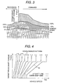
- Fig. 3 shows the torque characteristics of a target drive shaft, wherein the horizontal axis indicates the vehicle speed "Vsp” while the vertical axis the target drive shaft torque "TTqOut". It is assumed that an upper side than an intersection point of the two (2) axes mentioned above is in the positive direction of the target drive shaft torque "TTqOut", while a lower side in the negative direction thereof. Also, a right-hand side than the intersection point indicates an advance or forward movement, while the left-hand side a retreat or backward movement. Solid lines depict the acceleration pedal depression amounts “ ⁇ ”, and dotted lines the brake pedal depression force " ⁇ ".
- the above-mentioned target drive shaft torque "TTqOut” is turned to the positive, so that creep torque is generated in the manner similar to an AT car equipped with a torque converter, and when the remaining capacity of the battery 49 is larger than a predetermined value, the car runs with the driving power of the first motor 29 and the second motor 30 mentioned above. Or, when the remaining capacity of the battery 49 is smaller than the predetermined value, the car runs with the driving power of the engine 1.
- explanation will be given on a driving areas or regions of applying the engine 1 and the first motor 20, and the second motor 30.
- a meshed area in the figure indicates an area of motor driving, while an area with slanting lines indicates that of engine driving or driving area of both the engine and the motor in common.
- the car should be driven by only using the motors, i.e., the first motor 29 and the second motor 30, from a viewpoint of the driving performances or drivability, such as, comfortableness of riding in a car and/or responsibility.
- Fig. 4 shows, for bringing the drive range of the engine 1, the first motor 29 and the second motor 30 up to further high efficiency, characteristics of the gear-shift command "Ss" to the gear-type transmission 100.
- solid line indicate up-shift line (for example, from the 1 st speed to the 2 nd speed) while broken line down-shift line (for example, from the 2 nd speed to the 1 st speed)
- the gear-shift command "Ss" is determined by the vehicle speed "Vsp" and the target drive shaft torque "TTqOut”.
- the above gear-shift command "Ss" is obtained in advance, at the values where the engine 1, the first motor 29 and the second motor 30 show the high efficiency within all of the driving ranges, through experiments or a simulation thereof, and they are memorized in a memory means (not shown in the figure) in the power train control unit 50 mentioned above.
- Fig. 5 shows an operation principle of a motor running mode
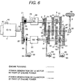
- Fig. 6 an alternator mode
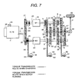
- Fig. 7 a charging while stopping mode and a series mode
- Fig. 8 a parallel mode
- Figs. 9 and 10 the operation principle of a series/parallel common mode.
- the motor running mode in Fig. 5 is a mode where the car is running by driving at least one of the first motor 29 and the second motor 30 with an output discharging from the battery 49.
- the first friction clutch 25 is released while the hub sleeve 3 is connected to the gear 31 directly, so as to set the gear-type transmission 100 at the 1 st speed in the transmission ratio, thereby traveling with the driving power of the first motor 29.
- the torque transmission route of the first motor 29 is, as indicated by solid lines in the figure: i.e., the first input shaft 23 ⁇ the hub sleeve 3 ⁇ the gear 31 ⁇ the gear 32 ⁇ the output shaft 27.
- the hub sleeve 9 may be connected to the gear 35 or 39 directly, thereby setting the transmission ratio of the gear-type transmission 100 at the 3 rd speed or the 5 th speed, so as to travel. It is also possible to release the second friction clutch 26 while connecting the hub sleeve 6 to the gear 33 directly, so as to set the transmission ratio of the gear-type transmission 100 at the 2 nd speed, thereby traveling with the driving power of the second motor 30.
- the torque transmission route of the first motor 29 is, as indicated by dotted lines in the figure: i.e., the second input shaft 24 ⁇ the hub sleeve 6 ⁇ the gear 33 ⁇ the gear 34 ⁇ the output shaft 27.
- the hub sleeve 14 may be connected to the gear 37 or 41 directly, thereby setting the transmission ratio of the gear-type transmission 100 at the 4 th speed or the 6 th speed, so as to travel. Further, in a case when the target drive shaft torque "TTqOut" is large, it is possible to drive the first motor and the second motor, simultaneously, so as to travel. In this instance, for escaping from interference in the torque between both, the first motor 29 and the second motor 30, both the first friction clutch 25 and the second friction clutch 26 are in the release condition.
- the alternator mode in Fig.6 is a mode where at least one of the first motor 29 and the second motor 30 is driven by a part of the motive power of the engine 1 for power generation during the traveling with the driving force of the engine 1, thereby to charge the battery with the output generated from the motor(s).
- the torque of the engine 1 is transmitted through the first input shaft 23.
- the first friction clutch 25 is closed while the second friction clutch 26 is released, so as to connect the hub sleeve 3 to the gear 3 directly, and the transmission ratio of the gear-type transmission 100 is set to the 1 st speed, thereby to travel with the driving force of the engine 1.
- the torque transmission route of the engine 1 is, as indicated by a solid line in the figure: i.e., the engine output shaft 19 ⁇ the gear 20 ⁇ the gear 21 ⁇ the first friction clutch 25 ⁇ the first input shaft 23 ⁇ the hub sleeve 3 ⁇ the gear 31 ⁇ the gear 32 ⁇ the output shaft 27, therefore as shown by a dotted line in the figure, it is possible to drive the first motor 29 to generate electricity with using a part of the driving force of the engine 1. Further, connecting of the hub sleeve 6 to the gear 33 directly, or connecting the hub sleeve 14 to the gear 37 or 41 directly, as is shown by a one-dotted chain lines in the figure, enables driving of the second motor 30 to generate electricity therefrom.
- the alternator mode mentioned above can be also achieved, in the similar manner, in a case where the hub sleeve 9 is connected to the gear 35 or 39 directly, and where the transmission ratio of the gear-type transmission 100 is set at the 3 rd speed or the 5 th speed, thereby traveling with the driving force of the engine 1.
- the torque of the engine 1 is transmitted through the second input shaft.
- the first friction clutch 25 is released while the second friction clutch 26 is closed, and the hub sleeve 6 is connected to the gear 33 directly, so as to set the transmission ratio of the gear-type transmission 100 at the 2 nd speed, thereby to travel with the driving force of the engine 1.
- the torque transmission route of the engine 1 is: i.e., the engine output shaft 19 ⁇ the gear 20 ⁇ the gear 22 ⁇ the second friction clutch 26 ⁇ the second input shaft 24 ⁇ the hub sleeve 6 ⁇ the gear 33 ⁇ the gear 34 ⁇ the output shaft 27, therefore it is possible to drive the second motor 30 to generate electricity with using a part of the driving force of the engine 1.
- connecting the hub sleeve 3 to the gear 31 directly, or connecting the hub sleeve 9 to the gear 35 or 39 directly enables driving of the first motor 29 to generate electricity therefrom. Also, when driving only the second motor, so as to generate electricity therefrom, it is preferable to turn both the hub sleeves 3 and 9 into the neutral condition, thereby cutting off the first motor so as to reduce the fuel consumption of the engine 1. Further, the alternator mode mentioned above can be achieved also, in the similar manner, in a case where the hub sleeve 14 is connected to the gear 37 or 41 directly, and where the transmission ratio of the gear-type transmission 100 is set at the 4 th speed or the 6 th speed, thereby traveling with the driving force of the engine 1.
- the charge while stopping mode in Fig. 7 is a mode where at least one of the first motor 29 and the second motor 30 is driven to generate electricity therefrom by the engine 1, under the condition that a car is stopping.
- the series mode is a mode where the other motor is driven by an output generated by either one of the first motor 29 or the second motor 30, thereby traveling.
- the torque transmission route of the engine 1 is as indicated by a solid line in the figure: i.e., the engine output shaft 19 ⁇ the gear 20 ⁇ the gear 22 ⁇ the second friction clutch 26 ⁇ the second input shaft 24 ⁇ the second motor 30, therefore since the torque transmission to the output shaft 27 is cut off, it is possible to drive the second motor 30 to generate electricity therefrom, under the condition that the car is stopped.
- the series mode In this case, the first friction clutch 25 is released while the second friction clutch 26 closed. And, the hub sleeve 3 is connected to the gear 31 directly, while all of the hub sleeves 9, 6 and 14 are in the neutral condition.
- the torque transmission route of the engine 1 is same to that under the charge while stopping mode mentioned above, therefore it is possible to drive the second motor 30 to generate electricity therefrom. It is also possible to drive the first motor 29 with the output generated by the second motor 30, to travel, wherein the torque transmission route of the first motor 29 in this instance is, as indicated by the dotted line in the figure: i.e., the first input shaft 23 ⁇ the gear 31 ⁇ the gear 32 ⁇ the output shaft 27. In this manner, when an intention to start by the driver is detected through the operation upon the acceleration pedal by the driver in the charge while stopping mode, the series mode is achieved, in which the first motor 29 is driven to travel while the second motor 30 is driven to generate electricity by the engine 1, thereby enabling immediate start with smoothness.
- the parallel mode in Fig. 8 is a mode where any one of the first motor 29 or the second motor 30 is driven to assist the acceleration with an output discharging from the battery 49 during traveling with the driving power of the engine 1, thereby improving the driving performance or drivability of the car.
- the first friction clutch 25 is closed while the second friction clutch 26 released, and the hub sleeve 3 is directly connected to the gear 31 while the hub sleeve 9 in the neutral condition.
- the torque transmission route of the engine 1 is, as indicated by the solid line in the figure: i.e., the engine output shaft 19 ⁇ the gear 20 ⁇ the gear 21 ⁇ the first friction clutch 25 ⁇ the first input shaft 23 ⁇ the hub sleeve 3 ⁇ the gear 31 ⁇ the gear 32 ⁇ the output shaft 27.
- the target drive shaft torque "TTqOut" comes to be large due to depression of the acceleration pedal by the driver, since there occurs a response delay a little bit on the torque of the engine 1, therefore it is preferable to provide an acceleration assist by means of the driving power of a motor having a relatively small response delay.
- the torque transmission route of the first motor 29 is, as indicated by the dotted line in the figure: i.e., the first input shaft 23 ⁇ the hub sleeve 3 ⁇ the gear 31 ⁇ the gear 32 ⁇ the output shaft 27, therefore it is possible to obtain the acceleration assist. Also, by connecting the hub sleeve 6 to the gear 33 directly, or connecting the hub sleeve 14 to the gear 37 or 41 directly, it is possible to drive the second motor 30, so as to achieve the acceleration assist.
- the torque transmission route of the second motor 30 is, as indicated by the one-dotted chain line in the figure: i.e., the second input shaft 24 ⁇ the hub sleeve 6 ⁇ the gear 33 ⁇ the gear 34 ⁇ the output shaft 27.
- the parallel mode mentioned above can be achieved also in the case where the car is running with the driving power of the engine 1, wherein the hub sleeve 3 is in the neutral condition while the hub sleeve 9 is directly connected to the gear 35 or 39, so as to set the transmission ratio at the 3 rd speed or the 5 th speed, thereby traveling with the driving power of the engine 1.
- the torque transmission route of the engine 1 is: i.e., the engine output shaft 19 ⁇ the gear 20 ⁇ the gear 22 ⁇ the second friction clutch 26 ⁇ the second input shaft 24 ⁇ the hub sleeve 6 ⁇ the gear 33 ⁇ the gear 34 ⁇ the output shaft 27.
- the target drive shaft torque "TTqOut" comes to be large due to depression of the acceleration pedal by the driver, since there occurs a response delay a little bit on the torque of the engine 1, therefore it is preferable to provide an acceleration assist by means of the driving power of a motor having a relatively small response delay.
- the torque transmission route of the first motor 29 is: i.e., the second input shaft 24 ⁇ the hub sleeve 6 ⁇ the gear 33 ⁇ the gear 34 ⁇ the output shaft 27, therefore it is possible to obtain the acceleration assist. Also, with connecting the hub sleeve 3 to the gear 31 directly, or connecting the hub sleeve 9 to the gear 35 or 39 directly, it is possible to drive the first motor 29, so as to achieve the acceleration assist.
- the torque transmission route of the first motor 29 is: i.e., the first input shaft 23 ⁇ the hub sleeve 3 ⁇ the gear 31 ⁇ the gear 32 ⁇ the output shaft 27.
- the parallel mode mentioned above can be achieved also in the case where the car is running with the driving power of the engine 1, wherein the hub sleeve 6 is in the neutral condition while the hub sleeve 14 is directly connected with the gear 37 or 41, so as to set the transmission ratio at the 4 th speed or the 6 th speed.
- the series/parallel common mode in Fig. 9 is a mode where any one of the first motor 29 and the second motor 30 is driven by a part of the motive power of the engine 1, during traveling with the driving power of the engine 1, thereby achieving the acceleration assist through the driving power of the other motor with an output of power generation obtained therefrom.
- the torque transmission route of the engine 1 is, as indicated by the solid line in the figure: i.e., the engine output shaft 19 ⁇ the gear 20 ⁇ the gear 21 ⁇ the first friction clutch 25 ⁇ the first input shaft 23 ⁇ the hub sleeve 3 ⁇ the gear 31 ⁇ the gear 32 ⁇ the output shaft 27.
- the torque transmission route of the first motor 29 is: i.e., the first input shaft 23 ⁇ the hub sleeve 3 ⁇ the gear 31 ⁇ the gear 32 ⁇ the output shaft 27.
- the series/parallel mode mentioned previously can be achieved also in the case where the hub sleeve 3 is in the neutral condition while the hub sleeve 9 is connected to the gear 35 or 39 directly, so as to set the transmission ratio of the gear-type transmission 100 at the 3 rd speed or the 5 th speed, thereby traveling with the driving power of the engine 1.
- the transmission ratio of the gear-type transmission 100 is set at the 2 nd speed, thereby traveling with the driving power of the engine 1.
- Both the first friction clutch 25 and the second friction clutch 26 are closed, and the hub sleeve 6 is directly connected with the gear 33 while the hub sleeve 14 in the neutral condition.
- both the hub sleeve 3 and the hub sleeve 9 are brought in the neutral condition.
- the torque transmission route of the engine 1 is: i.e., the engine output shaft 19 ⁇ the gear 20 ⁇ the gear 22 ⁇ the second friction clutch 26 ⁇ the second input shaft 24 ⁇ the hub sleeve 6 ⁇ the gear 33 ⁇ the gear 34 ⁇ the output shaft 27.
- the torque transmission route of the second motor 30 is: i.e., the second input shaft 24 ⁇ the hub sleeve 6 ⁇ the gear 33 ⁇ the gear 34 ⁇ the output shaft 27.
- the series/parallel mode mentioned above can be achieved also in the case where the hub sleeve 6 is brought in the neutral condition while the hub sleeve 14 is connected to the gear 35 or 39 directly, so as to set the transmission ratio of the gear-type transmission 100 at the 4 th speed or the 6 th speed, thereby traveling with the driving power of the engine 1.
- Fig. 10 shows a method for accomplishing the series/parallel common mode mentioned above, but upon the operation principle, which is different from that shown in the Fig. 9.
- the first friction clutch 25 is closed while the second friction clutch 26 released, and the hub sleeve 3 is directly connected to the gear 31 while the hub sleeve 9 in the neutral condition.
- the torque transmission route of the engine 1 is, as shown by the solid line in the figure: i.e., the engine output shaft 19 ⁇ the gear 20 ⁇ the gear 21 ⁇ the first friction clutch 25 ⁇ the first input shaft 23 ⁇ the hub sleeve 3 ⁇ the gear 31 ⁇ the gear 32 ⁇ the output shaft 27.
- the torque transmission route of the first motor 29 is: i.e., the first input shaft 23 ⁇ the hub sleeve 3 ⁇ the gear 31 ⁇ the gear 32 ⁇ the output shaft 27.
- the series/parallel mode mentioned above can be achieved also in the case where the hub sleeve 3 is in the neutral condition while the hub sleeve 9 is directly connected to the gear 35 or 39, so as to set the transmission ratio of the gear-type transmission 100 at the 3 rd speed or the 5 th speed, and it may be also possible to drive the second motor 30, so as to generate electricity therefrom, by bringing the hub sleeve 6 in the neutral condition while connecting the hub sleeve 14 to the gear 37 or 41 directly.
- the transmission ratio of the gear-type transmission 100 is set at the 2 nd speed, thereby running or teraveling the car with the driving power of the engine 1.
- the first friction clutch 25 is released while the second friction clutch 26 closed, and the hub sleeve 3 is directly connected to the gear 31 while the hub sleeve 9 in the neutral condition. Also, the hub sleeve 6 is directly connected to the gear 33, while the hub sleeve 14 in the neutral condition.
- the torque transmission route of the engine 1 is: i.e., the engine output shaft 19 ⁇ the gear 20 ⁇ the gear 22 ⁇ the second friction clutch 26 ⁇ the second input shaft 24 ⁇ the hub sleeve 6 ⁇ the gear 33 ⁇ the gear 34 ⁇ the output shaft 27.
- the torque transmission route of the second motor 30 is: i.e., the second input shaft 24 ⁇ the hub sleeve 6 ⁇ the gear 33 ⁇ the gear 34 ⁇ the output shaft 27.
- the series/parallel mode mentioned above can be achieved also in the case where the hub sleeve 6 is brought in the neutral condition while the hub sleeve 14 is directly connected to the gear 37 or 41, so as to set the transmission ratio of the gear-type transmission 100 at the 4 th speed or the 6 th speed, and it may be also possible to drive the first motor 29, so as to generate electricity therefrom, by bringing the hub sleeve 6 in the neutral condition while connecting the hub sleeve 14 to the gear 37 or 41 directly.
- the hub sleeve 6 is directly connected to the bear 33 while keeping the hub sleeve 14 in the neutral condition.
- the torque transmission route of the engine 1 under the condition of the 1 st speed is, as shown by an arrow of dotted line in the figure: i.e., the engine output shaft 19 ⁇ the gear 20 ⁇ the gear 21 ⁇ the first friction clutch 25 ⁇ the first input shaft 23 ⁇ the hub sleeve 3 ⁇ the gear 31 ⁇ the gear 32 ⁇ the output shaft 27.
- the gear-shift from the 1 st speed to the 2 nd speed is completed by closing the second friction clutch 26, gradually, while releasing the first friction clutch 25 gradually, so as to exchange the torque transmission route of the engine 1.
- the torque transmission route of the engine under the condition of the 2 nd speed is, as is shown by an arrow of solid line: i.e., the engine output shaft 19 ⁇ the gear 20 ⁇ the gear 22 ⁇ the second friction clutch 26 ⁇ the second input shaft 24 ⁇ the hub sleeve 6 ⁇ the gear 33 ⁇ the gear 34 ⁇ the output shaft 27.
- the transmission or gear-shift method for exchanging the first friction clutch 25 to the second friction clutch 26, in this manner is generally called by "clutch-to-clutch gearshift or transmission", and has a merit that the drive shaft torque will not be cut off during the transmission, therefore it is widely applied to, as a transmission method for AT (Automatic Transmission) equipped with a torque converter of the conventional art.
- AT Automatic Transmission
- the torque changes are suppressed when the clutches are exchanged.
- the torque transmission route of the motor 30 is, as is shown by the one-dotted chain line in the figure: i.e., the second input shaft 24 ⁇ the hub sleeve 6 ⁇ the gear 33 ⁇ the gear 34 ⁇ the output shaft 27, therefore it is possible to compensate the drive shaft torque (equal to the torque on the output shaft 27).
- Fig. 12 is a time chart for showing a control method when conducting the gear-shift from the 1 st speed to the 2 nd speed.
- This Fig. 12 shows the "time” on the horizontal axis, while on the veridical axis thereof, the gear-shift command "Ss", the depression amount " ⁇ ” of acceleration pedal, the depression force " ⁇ ” of brake pedal, the engine torque “Te”, the engine rotating speed “Ne”, the vehicle speed “Vsp”, the first friction clutch “Tc1” the second friction clutch “Tc2", the first motor torque “Tm1", the second motor torque “Tm2",and the output shaft torque "To”, respectively.
- the rotating speed "Ni1" of the first input shaft is indicated by the broken line while the rotating speed "Ni2" of the second input shaft by the one-dotted chain line, in addition to the chart of the engine rotating speed "Ne”, while the second motor torque "Tm2" and the output torque "To” are indicated by the solid lines when the control is conducted by the motor, or by the broken lines otherwise, thus control by the motor is not conducted (without the control).
- Running condition is in a case where the gear-shift command "Ss" is changed during when the car is running at a constant acceleration pedal depression amount " ⁇ ".
- the second friction clutch torque Tc2 reaches up to a predetermined value, and then the first friction clutch 25 is released, therefore the first friction clutch torque "Tc1" comes to zero (0).
- the first friction clutch torque "Tc1” is lowered down in a step-like manner herein, when the first friction clutch 25 is released, however the first friction clutch torque "Tc1 may be lowered gradually, from the point "a”.
- the first friction clutch 25 is released, the torque of the engine 1 is transmitted by means of only the second friction clutch 26, and then the engine rotating speed "Ne” decreases from the rotating speed "Ni1" of the first input shaft down to the rotating speed "Ni2" of the second input shaft, gradually.
- Ie indicates inertia on the engine side.
- the second clause of the equation (3) thus, the inertia torque on the engine side appears in the form of the torque changes on the output shaft.
- the second motor 30 is controlled, so as to suppress down the torque changes mentioned above.
- the control of the second motor during the gear-shift enables the suppression of the thrust (or push-up) on the output shaft torque due to the inertia torque during the gear-shift, thereby achieving a smooth gear-shift or transmission performance.
- the transmission method mentioned above can be also achieved by use of the first motor 29 mentioned above, in the similar manner, and it is applicable to all of the gear shifting patterns of carrying out the clutch-to-clutch gearshift.
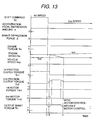
- Fig. 13 is a time chart for showing another control method, in particular, in a case of shifting from the 1 st speed to the 2 nd speed.
- the vertical and the horizontal axes are same to those of the time chart shown in the Fig. 12, and the running condition is also same to that shown in the Fig. 12.
- the second motor torque "Tm2" for reducing the "To_a” can be expressed by the following equation (8) because it is transmitted through the 2 nd speed gear train (i.e., the gears 33 and 34).
- the second motor torque Tm2 for reducing the " ⁇ To_b” mentioned above can be expressed by the following equation (11) because it is transmitted through the 2 nd speed gear train (i.e., the gears 33 and 34).
- controlling of the second motor 30 enables reduction of the drawn (or pull-in) on the output shaft torque between the points "b" and "c".
- controlling of the second motor in an initial period of the gear-shift, as well as, during the gear-shift enables the suppression of the drawn (or pull-in) of the output shaft torque due to the clutch-to-clutch gearshift or transmission, thereby achieving the smooth transmission performance.
- the transmission method mentioned above can be also realized by using the first motor 29 mentioned above, and it is applicable to all the transmission patterns of performing that clutch-to-clutch transmission.
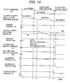
- Fig. 14 is a time chart for showing a method for performing preparation for transmission, in particular, in a case of the gearshift from the 2 nd speed to the 3 rd speed.
- This Fig. 14 shows the "time” on the horizontal axis, while on the veridical axis thereof, the gear-shift command "Ss", the first input shaft dog clutch position “DPOS1", the first input shaft rotating speed “Ni1”, the vehicle speed “Vsp”, the first friction clutch torque "Tc1", the second friction clutch torque “Tc2", the first motor torque "Tm1", the second motor torque “Tm2", and the output shaft torque "To”, respectively.
- the engine rotating speed "Ne” is indicated by the broken line while the second input shaft rotating speed “Ni2" by the one-dotted chain line, in addition to the chart of the first input shaft rotating speed “Ni1", and regarding the first motor torque “Tm1” and the first input shaft rotating speed “Ni1", they are depicted by the solid lines when conducting the control by means of the motor(s) while by the dotted lines when not (i.e., without the control).
- the acceleration pedal depression amount " ⁇ ” and the brake pedal depression force " ⁇ " are same to those shown in those Figs. 12 and 13.
- the rotating speed "Ni1" of the first input shaft 23 is controlled by means of the first motor 29 mentioned above, thereby preventing the synchronizer 10 from the wear-out thereof, when the hub sleeve 9 is connected to the gear 35 directly.
- the first motor 29 is controlled so that the rotating speed of the first input shaft 23 goes down.
- the torque transmission route of the engine 1 under the 3 rd speed condition is, as shown by an arrow of solid line: i.e., the engine output shaft 19 ⁇ the gear 20 ⁇ the gear 21 ⁇ the first friction clutch 25 ⁇ the first input shaft 23 ⁇ the hub sleeve 9 ⁇ the gear 35 ⁇ the gear 36 ⁇ the output shaft 27.
- the gearshift from the 3 rd speed to the 5 th speed is conducted by releasing the first friction clutch 25, and after the first friction clutch 25 is released, by releasing the hub sleeve 9 from the gear 35, so as to connect it to the gear 39 directly. After the hub sleeve 9 is connected to the gear 35 directly, the first friction clutch 25 is closed, thereby completing the gearshift.
- the torque transmission route of the engine 1 under the 5 th speed condition is, as shown by an arrow of solid line: i.e., the engine output shaft 19 ⁇ the gear 20 ⁇ the gear 21 ⁇ the first friction clutch 25 ⁇ the first input shaft 23 ⁇ the hub sleeve 9 ⁇ the gear 39 ⁇ the gear 40 ⁇ the output shaft 27.
- the hub sleeve 9 is changed from the one gear train (i.e., the gears 35 and 36) to the other gear train (i.e., the gears 39 and 40), and such the transmission method is same to that of the conventional MT (Manual Transmission) or an automatic MT (automatic Manual Transmission).
- Fig. 16 is a time chart for showing the control method in a case when shifting the gears from the 3 rd speed to the 5 th speed. This Fig.
- the engine rotating speed "Ne” is indicated by the broken line while the second input shaft rotating speed “Ni2" by the one-dotted chain line, in addition to the chart of the first input shaft rotating speed "Ni1", and regarding the first motor torque "Tm1" and the first input shaft rotating speed “Ni1” they are depicted by the solid lines when conducting the control by means of the motor while by the dotted lines when not (i.e., without the control).
- the hub sleeve 9 begins to be connected to the gear 39, and at the point “e” in the figure, it is directly connected thereto, completely.
- Ni1_ref No ⁇ G5 where, "No” indicates the rotating speed of the output shaft 27, and "G5" the transmission ratio at the 5 th speed. Determining by the equation (16) mentioned above allows to suppress the change in the first input shaft rotating speed "Ni1" when the hub sleeve 9 is directly connected to the gear 39, thereby enabling reduction of the wear-out of the synchronizer 12.
- the rotating speed control mentioned above can be also achieved by using the second motor, in the similar manner, even in the case where the gear train on the second input shaft 24 is changed by the hub sleeves 6 and 14, and it is also applicable to all of the transmission patterns without such the clutch-to-clutch control.
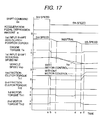
- Fig. 17 is a time chart for showing another control method, in particular, when shifting gears from the 3 rd speed to the 5 th speed.
- the vertical and the horizontal axes are same to those on the time chart shown in the Fig. 16, and the running condition is also same to that shown in the Fig. 16.
- the torque of the second motor 30 is determined to be that indicated by the following equation (23), thereby compensating or adjusting the torque reduction on the output shaft 27.
- the compensation control for torque reduction, due to the motor(s) mentioned above can be also achieved by using the first motor, in the similar manner, even when the gear train on the second input shaft 24 is changed by the hub sleeves 6 and 14, and it is applicable to all the transmission patterns without the clutch-to-clutch control.
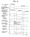
- Fig. 18 is a time chart for showing a control method, in particular, when shifting the gears from the 3 rd speed to the 5 th speed, but without releasing the first friction clutch 25.
- the vertical and the horizontal axes are same to those on the time chart shown in those Figs. 16 and 17, and the running condition is also same to that shown in those Figs. 16 and 17.
- the engine torque "Te” is reduced down, temporally, for performing the gearshift by changing the hub sleeve 9 from the gear 35 to the gear 39.
- the compensation control for torque reduction by means of the motors mentioned above can be also achieved by using the first motor, in the similar manner, even when changing the gear train on the second input shaft 24 by the hub sleeves 6 and 14, and it is applicable to all the transmission patterns without the clutch-to-clutch control.
- Fig. 19 shows the structure of an automobile system, according to another embodiment of the present invention.
- an electric control throttle 43 for controlling an amount of suction air and an engine rotating speed sensor 44 for measuring the engine rotating speed "Ne”.
- the first friction clutch 25 Between the engine output shaft 19 and the first input shaft 23 of a gear-type transmission 100b is provided the first friction clutch 25, so as to transmit the motive power of the engine 1 to the first input shaft 23.
- the second friction clutch 26 In the similar manner, between the engine output shaft 19 and the second input shaft 24 of the gear-type transmission 100b is provide the second friction clutch 26, so as to transmit the motive power of the engine 1 to the second input shaft 24.
- the first input shaft 23 has the cylindrical structure
- the second input shaft 24 has such the structure that it passes through the hollow portion of the first input shaft 23 mentioned above, therefore the first input shaft 23 is supported freely ratatable to the second input shaft.
- gears 1901, 31b, 35b and 39b in one body, in which the gear 1901 is also used as a detector of the first input shaft rotating speed "Ni1", and detection of rotation of the gear 1901 by a sensor 45a enables the detection of the rotating speed of the first input shaft 23.
- gears 1904, 33b, 37b and 41b in one body, in which the gear 1904 is also used as a detector of the second input shaft rotating speed "Ni2", and detection of rotation of the gear 1904 by a sensor 46a enables the detection of the rotating speed of the second input shaft 24.
- a first motor output shaft 1903 Onto a first motor output shaft 1903 is attached a gear 1902.
- the gear 1902 is always meshed with the gear 1901 mentioned above, and then it is possible to transmit the torque of the first motor 29 to the first input shaft 23 mentioned above.
- a second motor output shaft 1906 is attached a gear 1905.
- the gear 1905 is always meshed with the gear 1904 mentioned above, and then it is possible to transmit the torque of the second motor 30 to the second input shaft 24 mentioned above.
- a gear 1922 On the output shaft 27 are mounted: a gear 1922, a gear 32b equipped with a contact gear 1908 and a synchronizer 1909, a gear 36b equipped with a contact gear 1910 and a synchronizer 1911, a gear 40b equipped with a contact gear 1913 and a synchronizer 1914, a gear 34b equipped with a contact gear 1915 and a synchronizer 1916, a gear 38b equipped with a contact gear 1918 and a synchronizer 1919, a gear 42b equipped with a contact gear 1920 and a synchronizer 1921, a hub sleeve 1907 for directly connecting between the output shaft 27 and the gear 32b or the gear 36b, a hub sleeve 1912 for directly connecting between the output shaft 27 and the gear 40b or the gear 34b, and a hub sleeve 1917 for directly connecting between the output shaft 27 and the gear 328b or the gear 42b, being freely rotatable to the output shaft 27.
- the gear 1922 is also used as a detector of the output shaft rotating speed "No", and detection of the rotation of the gear 1922 by the sensor 47b enables the detection of the rotating speed of the output shaft 27.
- On the gears 32b, 36b, 40b, 34b, 38b and 42b are provide stoppers (not shown in the figure), for preventing them from moving in the axial direction of the output shaft 27.
- On the gears 32b, 36b, 40b, 34b, 38b and 42b are provide stoppers (not shown in the figure), for preventing them from moving in the axial direction of the output shaft 27.
- gutters not shown in the figure
- the hub sleeves 1907, 1912 and 1917 are formed gutters (not shown in the figure) to be meshed with plural numbers of gutters of the output shaft 27, so that the hub sleeves 1907, 1912 and 1917 are engaged with the output shaft 27, being allowed to make a relative movement in the axial direction of the output shaft 27, but restricted from a movement in the rotational direction thereof. Accordingly, the torque transferred
- the gear train made up from the gears 31b and 32b is the 1 st speed, that from the gears 41b and 42b the 2 nd speed, that from the gears 35b and 36b the 3 rd speed, that from the gears 37b and 38b the 4 th speed, that from the gears 39 and 40 the 5 th speed, and that from the gears 33b and 34b the 6 th speed, respectively, in the transmission steps.
- Fig. 20 is shown the torque transmission route under the motor running mode.
- the first friction clutch 25 is released while the hub sleeve 1907 is connected to the gear 32b directly, so as to set the transmission ratio of the gear-type transmission 100b at the 1 st speed, thereby traveling with the driving power of the engine 1.
- the torque transmission route of the first motor 29 is, as shown by the solid line in the figure: i.e., the first motor output shaft 1903 ⁇ the gear 1902 ⁇ the gear 1901 ⁇ the first input shaft 23 ⁇ the gear 31b ⁇ the gear 32b ⁇ the hub sleeve 1907 ⁇ the output shaft 27.
- the torque transmission route of the second motor 30 is, as shown by the dotted line in the figure: i.e., the second motor output shaft 1906 ⁇ the gear 1905 ⁇ the gear 1904 ⁇ the second input shaft 24 ⁇ the gear 41b ⁇ the gear 42b ⁇ the hub sleeve 1917 ⁇ the output shaft 27.
- the target drive shaft torque "TTqOut" is large, it is possible to travel with driving the first motor 29 and the second motor 30, simultaneously. In this instance, it is preferable to bring both the first friction clutch 25 and the second friction clutch 26 into the released condition, so as to prevent from interference in the torques with each other between the first motor 29 and the second motor 30.
- a power transmission apparatus for use in an automobile, comprising: (a) an engine; a gear-type transmission having: (b1) a first input shaft to which motive power is transmitted from said engine through a first friction clutch; (b2) a second input shaft to which motive power is transmitted from said engine through a second friction clutch; (b3) plural numbers of gear trains provided between said first input shaft and an output shaft and between said second input shaft and said output shaft; and (b4) a claw clutch provided on said gear trains; (c) a first motor connected to said first input shaft; and (d) a second motor connected to said second input shaft, since various driving modes can be realized, as well as, the small-sizing of the motors, thereby enabling to establish and/or satisfy both the reduction of fuel efficiency (or , mileage) and the drivability due to the small-sizing and the weight-lightening of the power transmission apparatus.
Landscapes
- Engineering & Computer Science (AREA)
- Mechanical Engineering (AREA)
- Chemical & Material Sciences (AREA)
- Combustion & Propulsion (AREA)
- Transportation (AREA)
- General Engineering & Computer Science (AREA)
- Automation & Control Theory (AREA)
- Hybrid Electric Vehicles (AREA)
- Electric Propulsion And Braking For Vehicles (AREA)
- Control Of Transmission Device (AREA)
- Structure Of Transmissions (AREA)
Abstract
Description
Claims (8)
- A power transmission apparatus for use in an automobile, comprising:either one of said first motor (29) and said second motor (30) is driven so that reduction of torque on said output shaft (27) is compensated, when conducting gear-shift through change-over of said gear trains (31-42; 31b-42b) by means of said claw clutch.(a) an engine (1);a gear-type transmission (100; 100b) having: (b1) a first input shaft (23) to which motive power is transmitted from said engine (1) through a first friction clutch (25); (b2) a second input shaft (24) to which motive power is transmitted from said engine (1) through a second friction clutch (26); (b3) plural numbers of gear trains (31-42; 31b-42b) provided between said first input shaft (23) and an output shaft (27) and between said second input shaft (24) and said output shaft (27); and (b4) a claw clutch provided on said gear trains (31-42; 31b-42b);(c) a first motor (29) connected to said first input shaft (23); and(d) a second motor (30) connected to said second input shaft (24), wherein,
- A power transmission apparatus for use in an automobile, comprising:either one of said first motor (29) and said second motor (30) is driven so that torque fluctuation on said output shaft (27) is suppressed, when conducting gear-shift through change-over between said first friction clutch (25) and said second friction clutch (26).(a) an engine (1);a gear-type transmission (100; 100b) having: (b1) a first input shaft (23) to which motive power is transmitted from said engine (1) through a first friction clutch (25); (b2) a second input shaft (24) to which motive power is transmitted from said engine (1) through a second friction clutch (26); (b3) plural numbers of gear trains (31-42; 31b-42b) provided between said first input shaft (23) and an output shaft (27) and between said second input shaft (24) and said output shaft (27); and (b4) a claw clutch provided on said gear trains (31-42; 31b-42b);(c) a first motor (29) connected to said first input shaft (23); and(d) a second motor (30) connected to said second input shaft (24), wherein,
- A power transmission apparatus, as described in either one of the claims 1 and 2, wherein either one of said first motor (29) or said second motor (30) is driven so that wear-out of said claw clutch is suppressed by controlling either one of said first input shaft (23) and said second input shaft (24), when conducting gear-shift through change-over of said gear trains (31-42; 31b-42b) by means of said claw clutch.
- A power transmission apparatus for use in an automobile, comprising:either one of said first motor (29) and said second motor (30) is driven with an output discharged from said battery (49), for traveling.(a) an engine (1);a gear-type transmission (100; 100b) having: (b1) a first input shaft (23) to which motive power is transmitted from said engine (1) through a first friction clutch (25); (b2) a second input shaft (24) to which motive power is transmitted from said engine (1) through a second friction clutch (26); (b3) plural numbers of gear trains (31-42; 31b-42b) provided between said first input shaft (23) and an output shaft (27) and between said second input shaft (24) and said output shaft (27); and (b4) a claw clutch provided on said gear trains (31-42; 31b-42b);(c) a first motor (29) connected to said first input shaft (23);(d) a second motor (30) connected to said second input shaft (24); and(e) a battery (49) being charged with an output generated either one of said first motor (29) and said second motor(30), wherein,
- A power transmission apparatus for use in an automobile, comprising:electric power generation is conducted through driving either one of said first motor (29) or said second motor (30) by a part of motive power of said engine (1), so as to charge said battery (49) with generated output obtained by the electric power generation, during traveling with driving power of said engine (1).(a) an engine (1);a gear-type transmission (100; 100b) having: (b1) a first input shaft (23) to which motive power is transmitted from said engine (1) through a first friction clutch (25); (b2) a second input shaft (24) to which motive power is transmitted from said engine (1) through a second friction clutch (26); (b3) plural numbers of gear trains (31-42; 31b-42b) provided between said first input shaft (23) and an output shaft (27) and between said second input shaft (24) and said output shaft (27); and (b4) a claw clutch provided on said gear trains (31-42; 31b-42b);(c) a first motor (29) connected to said first input shaft (23);(d) a second motor (30) connected to said second input shaft (24); and(e) a battery (49) being charged with an output generated either one of said first motor (29) and said second motor (30), wherein,
- A power transmission apparatus for use in an automobile, comprising:either one of said first motor (29) and said second motor (30) is driven by said engine (1) so as to conduct electric power generation, when a vehicle stops and if remaining capacity of said battery (49) is less than a predetermined value, thereby charging said battery (49) with generated output obtained through the electric power generation.(a) an engine (1);a gear-type transmission (100; 100b) having: (b1) a first input shaft (23) to which motive power is transmitted from said engine (1) through a first friction clutch (25); (b2) a second input shaft (24) to which motive power is transmitted from said engine (1) through a second friction clutch (26); (b3)plural numbers of gear trains (31-42; 31b-42b) provided between said first input shaft (23) and an output shaft (27) and between said second input shaft (24) and said output shaft (27); and (b4) a claw clutch provided on said gear trains (31-42; 31b-42b);(c) a first motor (29) connected to said first input shaft (23);(d) a second motor (30) connected to said second input shaft (24); and(e) a battery (49) being charged with an output generated either one of said first motor (29) and said second motor (30), wherein,
- A power transmission apparatus for use in an automobile, comprising:either one of said first motor (29) and said second motor (30) is driven by said engine (1), so as to conduct electric power generation, while the other is driven with generated output obtained through the electric power generation, thereby to travel.(a) an engine (1);a gear-type transmission (100; 100b) having: (b1) a first input shaft (23) to which motive power is transmitted from said engine (1) through a first friction clutch (25); (b2) a second input shaft (24) to which motive power is transmitted from said engine (1) through a second friction clutch (26); (b3) plural numbers of gear trains (31-42; 31b-42b) provided between said first input shaft (23) and an output shaft (27) and between said second input shaft (24) and said output shaft (27); and (b4) a claw clutch provided on said gear trains (31-42; 31b-42b);(c) a first motor (29) connected to said first input shaft (23); and(d) a second motor (30) connected to said second input shaft (24), wherein,
- A power transmission apparatus for use in an automobile, comprising:either one of said first motor (29) and said second motor (30) is driven with an output discharged from said battery (49), thereby to assist driving power of said engine (1).(a) an engine (1);a gear-type transmission (100; 100b) having: (b1) a first input shaft (23) to which motive power is transmitted from said engine (1) through a first friction clutch (25); (b2) a second input shaft (24) to which motive power is transmitted from said engine (1) through a second friction clutch (26); (b3) plural numbers of gear trains (31-42; 31b-42b) provided between said first input shaft (23) and an output shaft (27) and between said second input shaft (24) and said output shaft (27); and (b4) a claw clutch provided on said gear trains (31-42; 31b-42b);(c) a first motor (29) connected to said first input shaft (23);(d) a second motor (30) connected to said second input shaft (24); and(e) a battery (49) being charged with an output generated either one of said first motor (29) and said second motor (30), wherein,
Applications Claiming Priority (2)
| Application Number | Priority Date | Filing Date | Title |
|---|---|---|---|
| JP2001184205 | 2001-06-19 | ||
| JP2001184205 | 2001-06-19 |
Publications (2)
| Publication Number | Publication Date |
|---|---|
| EP1270301A2 true EP1270301A2 (en) | 2003-01-02 |
| EP1270301A3 EP1270301A3 (en) | 2007-02-21 |
Family
ID=19024003
Family Applications (1)
| Application Number | Title | Priority Date | Filing Date |
|---|---|---|---|
| EP02002038A Withdrawn EP1270301A3 (en) | 2001-06-19 | 2002-02-07 | Power transmission apparatus for automobile |
Country Status (2)
| Country | Link |
|---|---|
| US (1) | US7150698B2 (en) |
| EP (1) | EP1270301A3 (en) |
Cited By (46)
| Publication number | Priority date | Publication date | Assignee | Title |
|---|---|---|---|---|
| WO2005009770A1 (en) * | 2003-07-25 | 2005-02-03 | Robert Bosch Gmbh | Regulating strategy for electromechanically power-branching hybrid drives |
| EP1559603A1 (en) * | 2004-01-27 | 2005-08-03 | LuK Lamellen und Kupplungsbau Beteiligungs KG | Method for upshifting a gearbox with two input shafts |
| EP1574756A1 (en) * | 2004-03-12 | 2005-09-14 | Röchling Getriebe OHG | Transmission |
| DE102004012767A1 (en) * | 2004-03-15 | 2005-10-20 | Deere & Co | Drive system for a vehicle |
| EP1610038A1 (en) * | 2004-06-21 | 2005-12-28 | Getrag Ford Transmissions GmbH | Double coupling transmission |
| EP1504946A3 (en) * | 2003-08-06 | 2006-04-19 | Nissan Motor Co., Ltd. | Transmission for an hybrid vehicle |
| DE102005007966A1 (en) * | 2005-02-22 | 2006-10-05 | Zf Friedrichshafen Ag | Drive train of a motor vehicle and method for operating the drive train |
| WO2007042109A1 (en) * | 2005-10-13 | 2007-04-19 | Volkswagen Aktiengesellschaft | Twin clutch gearbox for a motor vehicle, in particular provided with a hybrid drive and a method for controlling said twin clutch gearbox |
| DE102005049992A1 (en) * | 2005-10-12 | 2007-04-26 | Getrag Getriebe- Und Zahnradfabrik Hermann Hagenmeyer Gmbh & Cie Kg | Drive train for a cross country four-wheel drive vehicle, with a twin-clutch gearbox, has electric machines at both part-drives acting as generators or motors |
| WO2007090761A1 (en) * | 2006-02-10 | 2007-08-16 | Robert Bosch Gmbh | Method for operating a drive apparatus of a hybrid vehicle |
| GB2438293A (en) * | 2006-05-12 | 2007-11-21 | Ford Global Tech Llc | Hybrid electric vehicle powertrain for two and four wheel drive |
| WO2008138387A1 (en) * | 2007-05-14 | 2008-11-20 | Fev Motorentechnik Gmbh | Method for the operation of a hybrid drive system and hybrid drive system comprising two sub-gearboxes |
| GB2451246A (en) * | 2007-07-21 | 2009-01-28 | John Gordon Madge | Powershift gearbox with synchronizing and energy recovery power units |
| EP2088046A4 (en) * | 2006-11-22 | 2010-06-02 | Toyota Motor Co Ltd | POWER OUTPUT DEVICE, MOTOR VEHICLE EQUIPPED WITH POWER OUTPUT DEVICE AND CONTROL METHOD OF POWER OUTPUT DEVICE |
| EP2088047A4 (en) * | 2006-11-22 | 2010-06-02 | Toyota Motor Co Ltd | POWER GENERATING DEVICE, AUTOMOTIVE WITH THE POWER GENERATING DEVICE, AND POWER DEVICE CONTROLLING METHOD |
| US7798030B2 (en) | 2004-10-16 | 2010-09-21 | Daimler A.G. | Twin clutch transmission design with selective hybrid power transfer compatibility |
| EP1507993B1 (en) * | 2002-05-28 | 2012-04-04 | Eaton Corporation | Hybrid powertrain system |
| EP2450597A1 (en) * | 2010-11-09 | 2012-05-09 | Technische Universität Darmstadt | Invention relating to electric drive |
| EP2468553A1 (en) * | 2010-12-21 | 2012-06-27 | Saab Automobile AB | A vehicle powertrain arrangement |
| AT510966B1 (en) * | 2011-06-09 | 2012-08-15 | Avl List Gmbh | GEARBOX, ESPECIALLY DOUBLE CLUTCH GEARBOX |
| WO2012167970A1 (en) * | 2011-06-07 | 2012-12-13 | Robert Bosch Gmbh | Method for operating a driving device and device for operating the driving device |
| WO2013060431A1 (en) * | 2011-10-26 | 2013-05-02 | Audi Ag | Drive assembly for a hybrid drive for motor vehicles |
| CN103213490A (en) * | 2012-12-07 | 2013-07-24 | 常州万安汽车部件科技有限公司 | Multi-speed-ratio multi-mode hybrid power system and driving mode thereof |
| DE102013109671A1 (en) | 2012-09-06 | 2014-03-06 | Avl List Gmbh | Dual clutch transmission for e.g. lorry, has countershaft drive connected with output shaft or input via gear wheel stage, which is directly connected with same element of auxiliary transmission as output shaft and/or with output shaft |
| WO2014045092A1 (en) * | 2012-09-19 | 2014-03-27 | Toyota Jidosha Kabushiki Kaisha | Control device for hybrid vehicle |
| EP2743548A1 (en) | 2012-12-12 | 2014-06-18 | AVL List GmbH | Method for operating a dual clutch transmission |
| ITBO20130291A1 (en) * | 2013-06-11 | 2014-12-12 | Ferrari Spa | ROAD VEHICLE WITH HYBRID PROPULSION |
| EP2926033A4 (en) * | 2012-11-29 | 2016-08-10 | Mack Trucks | Series hybrid transmission and gear-shifting method for a series hybrid transmission |
| WO2018000961A1 (en) * | 2016-06-29 | 2018-01-04 | 比亚迪股份有限公司 | Power drive system and vehicle |
| WO2018000960A1 (en) * | 2016-06-29 | 2018-01-04 | 比亚迪股份有限公司 | Power drive system and vehicle |
| WO2018000964A1 (en) * | 2016-06-29 | 2018-01-04 | 比亚迪股份有限公司 | Power drive system and vehicle |
| WO2018000957A1 (en) * | 2016-06-29 | 2018-01-04 | 比亚迪股份有限公司 | Power drive system and vehicle |
| WO2018000959A1 (en) * | 2016-06-29 | 2018-01-04 | 比亚迪股份有限公司 | Power drive system and vehicle |
| WO2018000963A1 (en) * | 2016-06-29 | 2018-01-04 | 比亚迪股份有限公司 | Power drive system and vehicle |
| WO2018000962A1 (en) * | 2016-06-29 | 2018-01-04 | 比亚迪股份有限公司 | Power drive system and vehicle |
| WO2018000955A1 (en) * | 2016-06-29 | 2018-01-04 | 比亚迪股份有限公司 | Power drive system and vehicle |
| EP3473894A1 (en) * | 2017-10-20 | 2019-04-24 | Ningbo Geely Automobile Research & Development Co. Ltd. | Method for synchronisation of a first transmission component |
| CN111114281A (en) * | 2018-10-31 | 2020-05-08 | 比亚迪股份有限公司 | Powertrain and Vehicles |
| WO2020177885A1 (en) * | 2019-03-05 | 2020-09-10 | Zf Friedrichshafen Ag | Hybrid powertrain for a motor vehicle, and method for operating a hybrid powertrain |
| WO2020177887A1 (en) * | 2019-03-05 | 2020-09-10 | Zf Friedrichshafen Ag | Transmission assembly, motor vehicle powertrain, and method for operating same |
| WO2020177905A1 (en) * | 2019-03-05 | 2020-09-10 | Zf Friedrichshafen Ag | Hybrid transmission assembly, motor vehicle powertrain, and motor vehicle |
| WO2020182324A1 (en) * | 2019-03-14 | 2020-09-17 | Zf Friedrichshafen Ag | Hybrid transmission device and motor vehicle |
| WO2020182325A1 (en) * | 2019-03-14 | 2020-09-17 | Zf Friedrichshafen Ag | Hybrid transmission device and motor vehicle |
| WO2020187429A1 (en) * | 2019-03-20 | 2020-09-24 | Zf Friedrichshafen Ag | Hybrid transmission device and motor vehicle |
| EP3829910A1 (en) * | 2018-08-03 | 2021-06-09 | Valeo Embrayages | Electric vehicle propulsion system |
| EP4242032A1 (en) * | 2022-03-10 | 2023-09-13 | Suzuki Motor Corporation | Hybrid vehicle |
Families Citing this family (91)
| Publication number | Priority date | Publication date | Assignee | Title |
|---|---|---|---|---|
| DE10021025A1 (en) * | 2000-05-02 | 2001-11-15 | Bosch Gmbh Robert | Gearboxes, in particular for motor vehicles |
| JP2002031224A (en) * | 2000-07-17 | 2002-01-31 | Hitachi Ltd | Automatic transmission control method and automatic transmission control device |
| DE10203760A1 (en) * | 2002-01-25 | 2003-08-07 | Bosch Gmbh Robert | Method for setting a target operating state of a hybrid drive of a vehicle |
| JP4038460B2 (en) * | 2003-09-04 | 2008-01-23 | 株式会社日立製作所 | Active shift transmission, transmission control device, and automobile |
| US7125362B2 (en) * | 2004-01-23 | 2006-10-24 | Eaton Corporation | Hybrid powertrain system including smooth shifting automated transmission |
| CA2573111C (en) * | 2004-07-07 | 2012-06-05 | Eaton Corporation | Shift point strategy for hybrid electric vehicle transmission |
| US20060112781A1 (en) * | 2004-11-30 | 2006-06-01 | Brian Kuras | Multi-motor/multi-range torque transmitting power system |
| DE102005004737A1 (en) * | 2005-02-02 | 2006-08-10 | Volkswagen Ag | Drive system for a motor vehicle with hybrid drive |
| CN102312963B (en) * | 2005-02-10 | 2015-03-11 | 博格华纳公司 | Power flow configuration for dual clutch transmission mechanism |
| JP2006273514A (en) * | 2005-03-29 | 2006-10-12 | Toyota Industries Corp | Hybrid forklift |
| US7507175B2 (en) * | 2005-03-31 | 2009-03-24 | Luk Lamellen Und Kupplungsbau Beteiligungs Kg | Power-branched continuously variable transmission |
| US7833119B2 (en) * | 2005-09-23 | 2010-11-16 | Gm Global Technology Corporation, Inc. | Powertrain with series electric launch and electric power assisted performance |
| JP2007177925A (en) * | 2005-12-28 | 2007-07-12 | Hitachi Ltd | Automobile control device, control method, and automatic transmission |
| DE102006003711A1 (en) * | 2006-01-26 | 2007-08-02 | Zf Friedrichshafen Ag | Method for control of vehicle with internal combustion engine and electric drive, comprises proportional reduction of torque at both drives |
| JP4887058B2 (en) * | 2006-02-22 | 2012-02-29 | 日立オートモティブシステムズ株式会社 | Control apparatus and control method for automobile |
| US7536927B2 (en) * | 2006-06-05 | 2009-05-26 | Brose Fahrzeugteile GmbH & Co. Kommanditgesellschaft, Würzburg | Window lift drive for raising and lowering windows in a vehicle door |
| JP5058527B2 (en) * | 2006-07-25 | 2012-10-24 | 矢崎総業株式会社 | Stepping motor drive device |
| DE102006041159B4 (en) * | 2006-09-01 | 2012-04-19 | Audi Ag | Hybrid drive device |
| US7803087B2 (en) * | 2006-10-17 | 2010-09-28 | Ford Global Technologies, Llc | System and method for controlling a vehicle |
| JP4140647B2 (en) * | 2006-10-24 | 2008-08-27 | トヨタ自動車株式会社 | Power output device and hybrid vehicle |
| FR2907719B1 (en) * | 2006-10-26 | 2009-06-12 | Inst Francais Du Petrole | MOVING DRIVE SYSTEM FOR A HYBRID VEHICLE AND METHOD USING SUCH A SYSTEM. |
| JP4072183B1 (en) * | 2006-11-09 | 2008-04-09 | 三菱重工業株式会社 | Work vehicle and power control method for work vehicle |
| US8118703B2 (en) * | 2006-12-01 | 2012-02-21 | Chrysler Group Llc | Hybrid transmission having synchronizers |
| US7891450B2 (en) * | 2007-02-21 | 2011-02-22 | Ford Global Technologies, Llc | System and method of torque transmission using an electric energy conversion device |
| US7713164B2 (en) * | 2007-06-26 | 2010-05-11 | Ford Global Technologies, Llc | Double step gear shifting in a hybrid electric vehicle |
| US7677135B2 (en) * | 2007-07-18 | 2010-03-16 | Hamilton Sundstrand Corporation | Electromechanical power transfer system with multiple dynamoelectric machines |
| JP4285571B2 (en) * | 2007-09-27 | 2009-06-24 | トヨタ自動車株式会社 | Vehicle drive device |
| EP2210758B1 (en) * | 2007-10-22 | 2015-06-24 | BYD Company Limited | Hybrid power driving system and driving method thereof |
| US7980980B2 (en) * | 2007-11-14 | 2011-07-19 | GM Global Technology Operations LLC | Hybrid powertrain |
| JP5218835B2 (en) * | 2008-09-18 | 2013-06-26 | アイシン精機株式会社 | Vehicle drive device |
| US8070649B2 (en) * | 2009-01-09 | 2011-12-06 | GM Global Technology Operations LLC | Hybrid powertrain and dual clutch transmission |
| US8172715B2 (en) * | 2009-02-03 | 2012-05-08 | Ford Global Technologies, Llc | Multiplexed gear actuation system for a dual clutch transmission |
| ITBO20090061A1 (en) * | 2009-02-09 | 2010-08-10 | Ferrari Spa | ROAD VEHICLE WITH HYBRID PROPULSION |
| JP5259469B2 (en) * | 2009-03-24 | 2013-08-07 | アイシン・エーアイ株式会社 | Transmission and shift control method for transmission |
| CN101936388B (en) * | 2009-06-29 | 2015-09-30 | 博格华纳公司 | Adopt the DCT speed changer of biaxial chain |
| CN102597572B (en) * | 2009-09-01 | 2014-12-03 | 株式会社日立Nico传动设备 | Twin clutch type hybrid transmission |
| CN102596614A (en) * | 2009-11-03 | 2012-07-18 | Tm4股份有限公司 | Hybrid vehicle transmission |
| US9045035B2 (en) | 2010-03-01 | 2015-06-02 | Borgwarner, Inc. | Single speed transmission for plugin hybrid electric vehicle with two disconnects |
| JP5136660B2 (en) * | 2010-07-08 | 2013-02-06 | 株式会社デンソー | Power transmission device for vehicle |
| JP5096552B2 (en) * | 2010-12-28 | 2012-12-12 | アイシン・エーアイ株式会社 | Vehicle power transmission control device |
| US8469858B2 (en) * | 2011-05-10 | 2013-06-25 | GM Global Technology Operations LLC | Hybrid vehicle with dual clutch transmission |
| CN102350939A (en) * | 2011-07-19 | 2012-02-15 | 东风汽车公司 | Driving system of hybrid electric vehicle |
| DE102011110444A1 (en) * | 2011-08-11 | 2013-02-14 | Getrag Ford Transmissions Gmbh | Hybrid powertrain |
| AT512935B1 (en) | 2012-04-03 | 2013-12-15 | Avl List Gmbh | Drive unit for a motor vehicle |
| CN102795103A (en) * | 2012-09-05 | 2012-11-28 | 刘丽君 | Dual-motor power assembly with intermediate shaft |
| KR101371745B1 (en) * | 2012-10-25 | 2014-03-07 | 기아자동차(주) | Control method for vehicle with dct |
| DE112014000581B4 (en) | 2013-01-28 | 2021-04-08 | Toyota Jidosha Kabushiki Kaisha | Hybrid vehicle |
| JP2014163410A (en) * | 2013-02-21 | 2014-09-08 | Aisin Seiki Co Ltd | Vehicle drive device |
| JP6186789B2 (en) * | 2013-03-25 | 2017-08-30 | アイシン精機株式会社 | Automatic transmission for automatic transmission for vehicle |
| JP6212893B2 (en) * | 2013-03-26 | 2017-10-18 | アイシン精機株式会社 | Dog clutch control device for automatic transmission |
| JP2014201132A (en) * | 2013-04-02 | 2014-10-27 | トヨタ自動車株式会社 | Vehicle control device |
| AT514542B1 (en) | 2013-06-06 | 2015-04-15 | Avl List Gmbh | Double clutch transmission for a motor vehicle |
| DE102013211591B4 (en) * | 2013-06-20 | 2024-03-28 | Zf Friedrichshafen Ag | Arrangement of a transmission and an electric machine for a hybrid drive and hybrid drive |
| KR101550605B1 (en) * | 2013-11-22 | 2015-09-08 | 현대자동차 주식회사 | Power transmission system of hybrid electric vehicle |
| KR101601431B1 (en) * | 2014-06-16 | 2016-03-09 | 현대자동차주식회사 | Hybrid powertrain for vehicle |
| KR101637686B1 (en) * | 2014-09-29 | 2016-07-08 | 현대자동차주식회사 | Hybrid transmission for vehicle |
| DE102015206190A1 (en) * | 2015-04-08 | 2016-10-13 | Bayerische Motoren Werke Aktiengesellschaft | Transmission device and switching method for a drive device with two electric machines |
| WO2016177392A1 (en) * | 2015-05-04 | 2016-11-10 | Volvo Truck Corporation | Method for disengaging an inactive gear of a dual clutch transmission and a corresponding transmission |
| SE538925C2 (en) | 2015-06-17 | 2017-02-21 | Scania Cv Ab | Method for changing gears in a drive system comprising an engine, two electric machines and a transmission |
| WO2017023854A1 (en) * | 2015-07-31 | 2017-02-09 | Massachusetts Institute Of Technology | Clutchless shifting of a manual transmission |
| KR101714221B1 (en) * | 2015-09-16 | 2017-03-08 | 현대자동차주식회사 | Power train system for hybrid electric vehicle |
| US9440640B1 (en) * | 2015-10-16 | 2016-09-13 | Borgwarner Inc. | Gear change torque fill strategy |
| WO2017192913A1 (en) | 2016-05-04 | 2017-11-09 | Massachusetts Institute Of Technology | Dual-shaft clutchless hybrid transmission |
| DE102016113690A1 (en) * | 2016-07-25 | 2018-01-25 | Technische Universität Darmstadt | Method for controlling a switching operation in a drive system and control device therefor |
| CN108099594B (en) * | 2016-11-25 | 2024-01-09 | 潍坊佩特来电器有限公司 | Dual-motor multimode pure electric system |
| DE102017223488B4 (en) | 2017-12-21 | 2019-09-26 | Audi Ag | Method for operating a drive device for a motor vehicle and corresponding drive device |
| FR3084621B1 (en) * | 2018-08-03 | 2021-09-10 | Valeo Embrayages | ELECTRIC VEHICLE PROPULSION SYSTEM |
| DE102019202948A1 (en) * | 2019-03-05 | 2020-09-10 | Zf Friedrichshafen Ag | Method for operating a motor vehicle, control device and motor vehicle |
| DE102019202973A1 (en) * | 2019-03-05 | 2020-09-10 | Zf Friedrichshafen Ag | Hybrid transmissions for motor vehicles and motor vehicle drive trains |
| DE102019202972A1 (en) * | 2019-03-05 | 2020-09-10 | Zf Friedrichshafen Ag | Hybrid transmission device and motor vehicle |
| DE102019202958B4 (en) * | 2019-03-05 | 2022-07-14 | Zf Friedrichshafen Ag | Hybrid transmission device and motor vehicle |
| DE102019202964A1 (en) * | 2019-03-05 | 2020-09-10 | Zf Friedrichshafen Ag | Drive train for a motor vehicle and a method for operating a drive train |
| DE102019202957A1 (en) * | 2019-03-05 | 2020-09-10 | Zf Friedrichshafen Ag | Hybrid transmission device and motor vehicle |
| DE102019202955A1 (en) * | 2019-03-05 | 2020-09-10 | Zf Friedrichshafen Ag | Hybrid transmission device and motor vehicle |
| DE102019204296B4 (en) * | 2019-03-27 | 2024-03-07 | Vitesco Technologies Germany Gmbh | Gear mechanism |
| US11254205B2 (en) * | 2019-04-11 | 2022-02-22 | Dana Heavy Vehicle Systems Group, Llc | Electric axle assembly |
| JP7215585B2 (en) * | 2019-08-29 | 2023-01-31 | 株式会社アイシン | Vehicle drive transmission device |
| US11519498B2 (en) | 2019-09-13 | 2022-12-06 | Ford Global Technologies, Llc | Methods and system for engine control during gear shifting in a hybrid electric vehicle |
| US11181174B2 (en) | 2019-11-07 | 2021-11-23 | Hyundai Motor Company | Powertrain for electric vehicle |
| US11927253B2 (en) | 2019-11-07 | 2024-03-12 | Hyundai Motor Company | Powertrain for electric vehicle |
| KR102803786B1 (en) | 2019-12-12 | 2025-05-02 | 현대자동차주식회사 | Power train for electric vehicle |
| JP7496875B2 (en) * | 2019-12-19 | 2024-06-07 | ボルボトラックコーポレーション | Gearbox for electric powertrain |
| DE102020207169A1 (en) * | 2020-06-08 | 2021-12-09 | Dana Belgium N.V. | Two-motor electric drive and control method |
| US11326668B1 (en) * | 2020-10-19 | 2022-05-10 | Kawasaki Jukogyo Kabushiki Kaisha | Dual clutch transmission-equipped power unit |
| KR102424448B1 (en) * | 2020-11-03 | 2022-07-22 | 현대자동차주식회사 | Shift conrtol method for vehicle |
| US12348087B2 (en) | 2021-02-08 | 2025-07-01 | Omni Powertrain Technologies, Llc | Rotor for axial flux motor and method of manufacture |
| US11982348B2 (en) * | 2021-10-01 | 2024-05-14 | Dana Belgium N.V. | Dual double synchronizer e-transmission for reducing torque interruption during gear shifts |
| EP4426574A4 (en) | 2021-12-03 | 2026-01-21 | Omni Powertrain Tech Llc | TWO-SPEED TRANSMISSION |
| US12104681B2 (en) * | 2023-01-10 | 2024-10-01 | Dana Belgium N.V. | Four speed countershaft transmission |
| DE102023205193A1 (en) * | 2023-06-02 | 2024-12-05 | Renk Gmbh | drive system and operating strategy for the drive system |
| US20260078820A1 (en) * | 2024-09-17 | 2026-03-19 | Dana Belgium N.V. | System and method for transmission shifting |
Family Cites Families (19)
| Publication number | Priority date | Publication date | Assignee | Title |
|---|---|---|---|---|
| FR1445735A (en) * | 1965-06-04 | 1966-07-15 | Improvements to synchronization devices for rotating shafts | |
| US5603242A (en) * | 1995-07-11 | 1997-02-18 | Caterpillar Inc. | Direct drive transmission apparatus and method for controlling shift |
| US5730676A (en) * | 1996-10-22 | 1998-03-24 | General Motors Corporation | Three-mode, input-split hybrid transmission |
| JP3644207B2 (en) * | 1997-08-19 | 2005-04-27 | 日産自動車株式会社 | Shift control device for hybrid vehicle |
| JPH11141665A (en) * | 1997-11-07 | 1999-05-25 | Kyowa Gokin Kk | Transmission for automobile |
| JP3336951B2 (en) | 1998-04-28 | 2002-10-21 | 株式会社日立製作所 | Automotive power transmission |
| US5935035A (en) * | 1998-06-24 | 1999-08-10 | General Motors Corporation | Electro-mechanical powertrain |
| WO2000026053A1 (en) * | 1998-11-03 | 2000-05-11 | Robert Bosch Gmbh | Hybrid transmission, especially for motor vehicles |
| DE19903936A1 (en) * | 1998-11-03 | 2000-05-04 | Bosch Gmbh Robert | Gearboxes, in particular for motor vehicles |
| DE19850549A1 (en) * | 1998-11-03 | 2000-05-04 | Bosch Gmbh Robert | Gearbox for a motor vehicle, in particular dual clutch manual gearbox, and method for operating the gearbox |
| JP4399116B2 (en) * | 1998-12-01 | 2010-01-13 | 日立オートモティブシステムズ株式会社 | Driving device and vehicle |
| JP3515006B2 (en) * | 1999-02-23 | 2004-04-05 | 本田技研工業株式会社 | Hybrid vehicle control device |
| DE19950679B4 (en) * | 1999-10-21 | 2010-01-07 | Volkswagen Ag | Automated dual-clutch transmission and method for controlling an automated dual-clutch transmission |
| DE19960621B4 (en) * | 1999-12-16 | 2006-12-21 | Daimlerchrysler Ag | Hybrid drive for vehicles |
| DE10165097B3 (en) * | 2000-07-18 | 2015-07-23 | Schaeffler Technologies AG & Co. KG | Double clutch |
| US6371878B1 (en) * | 2000-08-22 | 2002-04-16 | New Venture Gear, Inc. | Electric continuously variable transmission |
| US6499370B2 (en) * | 2001-01-10 | 2002-12-31 | New Venture Gear, Inc. | Twin clutch automated transaxle with motor/generator synchronization |
| US6427549B1 (en) * | 2001-01-10 | 2002-08-06 | New Venture Gear, Inc. | Dual countershaft twin clutch automated transmission |
| US6612386B2 (en) * | 2001-05-30 | 2003-09-02 | General Motors Corporation | Apparatus and method for controlling a hybrid vehicle |
-
2002
- 2002-02-07 EP EP02002038A patent/EP1270301A3/en not_active Withdrawn
- 2002-02-28 US US10/084,385 patent/US7150698B2/en not_active Expired - Lifetime
Cited By (69)
| Publication number | Priority date | Publication date | Assignee | Title |
|---|---|---|---|---|
| EP1507993B1 (en) * | 2002-05-28 | 2012-04-04 | Eaton Corporation | Hybrid powertrain system |
| US7668630B2 (en) | 2003-07-25 | 2010-02-23 | Robert Bosch Gmbh | Regulating strategy for electromechanically power-branching hybrid drives |
| WO2005009770A1 (en) * | 2003-07-25 | 2005-02-03 | Robert Bosch Gmbh | Regulating strategy for electromechanically power-branching hybrid drives |
| EP1504946A3 (en) * | 2003-08-06 | 2006-04-19 | Nissan Motor Co., Ltd. | Transmission for an hybrid vehicle |
| US7093517B2 (en) | 2003-08-06 | 2006-08-22 | Nissan Motor Co., Ltd. | Transmission for a vehicle |
| EP1559603A1 (en) * | 2004-01-27 | 2005-08-03 | LuK Lamellen und Kupplungsbau Beteiligungs KG | Method for upshifting a gearbox with two input shafts |
| US7166059B2 (en) | 2004-01-27 | 2007-01-23 | Luk Lamellen Und Kupplungsbau Beteilingungs Kg | Method for upshifting of a parallel shaft gear |
| EP1574756A1 (en) * | 2004-03-12 | 2005-09-14 | Röchling Getriebe OHG | Transmission |
| DE102004012767A1 (en) * | 2004-03-15 | 2005-10-20 | Deere & Co | Drive system for a vehicle |
| EP1610038A1 (en) * | 2004-06-21 | 2005-12-28 | Getrag Ford Transmissions GmbH | Double coupling transmission |
| US7798030B2 (en) | 2004-10-16 | 2010-09-21 | Daimler A.G. | Twin clutch transmission design with selective hybrid power transfer compatibility |
| DE102005007966A1 (en) * | 2005-02-22 | 2006-10-05 | Zf Friedrichshafen Ag | Drive train of a motor vehicle and method for operating the drive train |
| DE102005049992A1 (en) * | 2005-10-12 | 2007-04-26 | Getrag Getriebe- Und Zahnradfabrik Hermann Hagenmeyer Gmbh & Cie Kg | Drive train for a cross country four-wheel drive vehicle, with a twin-clutch gearbox, has electric machines at both part-drives acting as generators or motors |
| DE102005049992B4 (en) * | 2005-10-12 | 2014-03-13 | Getrag Getriebe- Und Zahnradfabrik Hermann Hagenmeyer Gmbh & Cie Kg | Method for controlling a drive train |
| WO2007042109A1 (en) * | 2005-10-13 | 2007-04-19 | Volkswagen Aktiengesellschaft | Twin clutch gearbox for a motor vehicle, in particular provided with a hybrid drive and a method for controlling said twin clutch gearbox |
| WO2007090761A1 (en) * | 2006-02-10 | 2007-08-16 | Robert Bosch Gmbh | Method for operating a drive apparatus of a hybrid vehicle |
| US8720619B2 (en) | 2006-02-10 | 2014-05-13 | Robert Bosch Gmbh | Method for operating a drive device of a hybird vehicle |
| CN101378929B (en) * | 2006-02-10 | 2012-08-08 | 罗伯特·博世有限公司 | Method and device for operating a hybrid vehicle drive |
| GB2438293A (en) * | 2006-05-12 | 2007-11-21 | Ford Global Tech Llc | Hybrid electric vehicle powertrain for two and four wheel drive |
| GB2438293B (en) * | 2006-05-12 | 2010-07-21 | Ford Global Tech Llc | Hybrid electric vehicle powertrain with four-wheel drive characteristics |
| CN101070051B (en) * | 2006-05-12 | 2012-07-18 | 福特环球技术公司 | Hybrid electric vehicle powertrain with four-wheel drive characteristics |
| US7462121B2 (en) | 2006-05-12 | 2008-12-09 | Ford Global Technologies, Llc | Hybrid electric vehicle powertrain with four-wheel drive characteristics |
| US8215426B2 (en) | 2006-11-22 | 2012-07-10 | Toyota Jidosha Kabushiki Kaisha | Power output apparatus, vehicle equipped with power output apparatus, and control method of power output apparatus |
| US8210296B2 (en) | 2006-11-22 | 2012-07-03 | Toyota Jidosha Kabushiki Kaisha | Power output apparatus, vehicle equipped with power output apparatus, and control method of power output apparatus |
| EP2088047A4 (en) * | 2006-11-22 | 2010-06-02 | Toyota Motor Co Ltd | POWER GENERATING DEVICE, AUTOMOTIVE WITH THE POWER GENERATING DEVICE, AND POWER DEVICE CONTROLLING METHOD |
| EP2088046A4 (en) * | 2006-11-22 | 2010-06-02 | Toyota Motor Co Ltd | POWER OUTPUT DEVICE, MOTOR VEHICLE EQUIPPED WITH POWER OUTPUT DEVICE AND CONTROL METHOD OF POWER OUTPUT DEVICE |
| US8979693B2 (en) | 2007-05-14 | 2015-03-17 | Fev Gmbh | Method for the operation of a hybrid drive system and hybrid drive system comprising two sub-transmissions |
| WO2008138387A1 (en) * | 2007-05-14 | 2008-11-20 | Fev Motorentechnik Gmbh | Method for the operation of a hybrid drive system and hybrid drive system comprising two sub-gearboxes |
| GB2451246A (en) * | 2007-07-21 | 2009-01-28 | John Gordon Madge | Powershift gearbox with synchronizing and energy recovery power units |
| EP2450597A1 (en) * | 2010-11-09 | 2012-05-09 | Technische Universität Darmstadt | Invention relating to electric drive |
| EP2468553A1 (en) * | 2010-12-21 | 2012-06-27 | Saab Automobile AB | A vehicle powertrain arrangement |
| CN103562600A (en) * | 2011-06-07 | 2014-02-05 | 罗伯特·博世有限公司 | Method for operating a driving device and device for operating the driving device |
| WO2012167970A1 (en) * | 2011-06-07 | 2012-12-13 | Robert Bosch Gmbh | Method for operating a driving device and device for operating the driving device |
| CN103562600B (en) * | 2011-06-07 | 2016-10-05 | 罗伯特·博世有限公司 | For running the method for driving means and for running the equipment of driving means |
| AT510966B1 (en) * | 2011-06-09 | 2012-08-15 | Avl List Gmbh | GEARBOX, ESPECIALLY DOUBLE CLUTCH GEARBOX |
| WO2012168116A1 (en) | 2011-06-09 | 2012-12-13 | Avl List Gmbh | Double clutch gearbox for a motor vehicle |
| WO2013060431A1 (en) * | 2011-10-26 | 2013-05-02 | Audi Ag | Drive assembly for a hybrid drive for motor vehicles |
| DE102013109671A1 (en) | 2012-09-06 | 2014-03-06 | Avl List Gmbh | Dual clutch transmission for e.g. lorry, has countershaft drive connected with output shaft or input via gear wheel stage, which is directly connected with same element of auxiliary transmission as output shaft and/or with output shaft |
| DE102013109671B4 (en) * | 2012-09-06 | 2020-11-19 | Avl List Gmbh | Double clutch transmission for a motor vehicle |
| WO2014045092A1 (en) * | 2012-09-19 | 2014-03-27 | Toyota Jidosha Kabushiki Kaisha | Control device for hybrid vehicle |
| EP2926033A4 (en) * | 2012-11-29 | 2016-08-10 | Mack Trucks | Series hybrid transmission and gear-shifting method for a series hybrid transmission |
| US9862374B2 (en) | 2012-11-29 | 2018-01-09 | Mack Trucks, Inc. | Series hybrid transmission and gear-shifting method for a series hybrid transmission |
| CN103213490A (en) * | 2012-12-07 | 2013-07-24 | 常州万安汽车部件科技有限公司 | Multi-speed-ratio multi-mode hybrid power system and driving mode thereof |
| EP2743548A1 (en) | 2012-12-12 | 2014-06-18 | AVL List GmbH | Method for operating a dual clutch transmission |
| ITBO20130291A1 (en) * | 2013-06-11 | 2014-12-12 | Ferrari Spa | ROAD VEHICLE WITH HYBRID PROPULSION |
| WO2018000955A1 (en) * | 2016-06-29 | 2018-01-04 | 比亚迪股份有限公司 | Power drive system and vehicle |
| WO2018000960A1 (en) * | 2016-06-29 | 2018-01-04 | 比亚迪股份有限公司 | Power drive system and vehicle |
| WO2018000959A1 (en) * | 2016-06-29 | 2018-01-04 | 比亚迪股份有限公司 | Power drive system and vehicle |
| WO2018000963A1 (en) * | 2016-06-29 | 2018-01-04 | 比亚迪股份有限公司 | Power drive system and vehicle |
| WO2018000962A1 (en) * | 2016-06-29 | 2018-01-04 | 比亚迪股份有限公司 | Power drive system and vehicle |
| WO2018000964A1 (en) * | 2016-06-29 | 2018-01-04 | 比亚迪股份有限公司 | Power drive system and vehicle |
| CN107539103A (en) * | 2016-06-29 | 2018-01-05 | 比亚迪股份有限公司 | Power-driven system and vehicle |
| WO2018000961A1 (en) * | 2016-06-29 | 2018-01-04 | 比亚迪股份有限公司 | Power drive system and vehicle |
| WO2018000957A1 (en) * | 2016-06-29 | 2018-01-04 | 比亚迪股份有限公司 | Power drive system and vehicle |
| CN107539103B (en) * | 2016-06-29 | 2020-07-10 | 比亚迪股份有限公司 | Power driving system and vehicle |
| EP3473894A1 (en) * | 2017-10-20 | 2019-04-24 | Ningbo Geely Automobile Research & Development Co. Ltd. | Method for synchronisation of a first transmission component |
| US11884259B2 (en) | 2017-10-20 | 2024-01-30 | Ningbo Geely Automobile Research & Development Co., Ltd. | Method for synchronisation of a first transmission component |
| US11584358B2 (en) | 2017-10-20 | 2023-02-21 | Ningbo Geely Automobile Research & Development Co., Ltd. | Method for synchronisation of a first transmission component |
| EP3829910A1 (en) * | 2018-08-03 | 2021-06-09 | Valeo Embrayages | Electric vehicle propulsion system |
| CN111114281A (en) * | 2018-10-31 | 2020-05-08 | 比亚迪股份有限公司 | Powertrain and Vehicles |
| CN111114281B (en) * | 2018-10-31 | 2021-07-09 | 比亚迪股份有限公司 | Powertrain and Vehicles |
| WO2020177885A1 (en) * | 2019-03-05 | 2020-09-10 | Zf Friedrichshafen Ag | Hybrid powertrain for a motor vehicle, and method for operating a hybrid powertrain |
| US20220176798A1 (en) * | 2019-03-05 | 2022-06-09 | Zf Friedrichshafen Ag | Hybrid Transmission Assembly, Motor Vehicle Powertrain, and Motor Vehicle |
| WO2020177905A1 (en) * | 2019-03-05 | 2020-09-10 | Zf Friedrichshafen Ag | Hybrid transmission assembly, motor vehicle powertrain, and motor vehicle |
| WO2020177887A1 (en) * | 2019-03-05 | 2020-09-10 | Zf Friedrichshafen Ag | Transmission assembly, motor vehicle powertrain, and method for operating same |
| WO2020182325A1 (en) * | 2019-03-14 | 2020-09-17 | Zf Friedrichshafen Ag | Hybrid transmission device and motor vehicle |
| WO2020182324A1 (en) * | 2019-03-14 | 2020-09-17 | Zf Friedrichshafen Ag | Hybrid transmission device and motor vehicle |
| WO2020187429A1 (en) * | 2019-03-20 | 2020-09-24 | Zf Friedrichshafen Ag | Hybrid transmission device and motor vehicle |
| EP4242032A1 (en) * | 2022-03-10 | 2023-09-13 | Suzuki Motor Corporation | Hybrid vehicle |
Also Published As
| Publication number | Publication date |
|---|---|
| US7150698B2 (en) | 2006-12-19 |
| US20020189397A1 (en) | 2002-12-19 |
| EP1270301A3 (en) | 2007-02-21 |
Similar Documents
| Publication | Publication Date | Title |
|---|---|---|
| US7150698B2 (en) | Power transmission apparatus for automobile | |
| JP3621916B2 (en) | Automotive power transmission device | |
| EP1122109B1 (en) | Hybrid car comprising a control device for gear shifting | |
| CN100412419C (en) | Over-Neutral Switching Control in Electric Variable Transmission | |
| EP1979184B1 (en) | Power output apparatus, vehicle including power output apparatus, and control unit and method for power output apparatus | |
| US7967721B2 (en) | Control apparatus for an automatic transmission | |
| US7125362B2 (en) | Hybrid powertrain system including smooth shifting automated transmission | |
| US6142907A (en) | Power transmission apparatus for an automobile | |
| JP3823728B2 (en) | Automatic transmission system | |
| US9090247B2 (en) | Control apparatus for vehicular drive system | |
| US6540642B2 (en) | Vehicle control system and vehicle control method | |
| CN107567554B (en) | Method for disengaging an inactive gear of a dual clutch transmission and corresponding transmission | |
| US8874289B2 (en) | Vehicular power transmission control apparatus | |
| EP1762452A2 (en) | Engine starting control device and method | |
| US8210985B2 (en) | Vehicular power transmission control apparatus | |
| US7367917B2 (en) | Shift change control system and automatic transmission system of automobile | |
| US8171824B2 (en) | Vehicular power transmission control apparatus | |
| JPWO2001066971A1 (en) | Automatic transmissions, rotating electrical machines, and automobiles | |
| CN101765530A (en) | Method for starting the combustion engine during a load shift in parallel hybrid vehicles | |
| CN101006299A (en) | Drive system, power output system including the drive system, vehicle equipped with the power output system, and drive system control method | |
| US20100262324A1 (en) | Vehicular power transmission control apparatus | |
| EP1937531B1 (en) | Shift control apparatus | |
| JP2007283878A (en) | POWER TRANSMISSION DEVICE, AUTOMOBILE MOUNTING THE SAME, AND METHOD FOR CONTROLLING POWER TRANSMISSION DEVICE | |
| JP4496762B2 (en) | Shift control device for motor four-wheel drive vehicle | |
| JP2006347408A (en) | Vehicle control apparatus, vehicle control method, and vehicle |
Legal Events
| Date | Code | Title | Description |
|---|---|---|---|
| PUAI | Public reference made under article 153(3) epc to a published international application that has entered the european phase |
Free format text: ORIGINAL CODE: 0009012 |
|
| AK | Designated contracting states |
Kind code of ref document: A2 Designated state(s): AT BE CH CY DE DK ES FI FR GB GR IE IT LI LU MC NL PT SE TR |
|
| AX | Request for extension of the european patent |
Free format text: AL;LT;LV;MK;RO;SI |
|
| PUAL | Search report despatched |
Free format text: ORIGINAL CODE: 0009013 |
|
| AK | Designated contracting states |
Kind code of ref document: A3 Designated state(s): AT BE CH CY DE DK ES FI FR GB GR IE IT LI LU MC NL PT SE TR |
|
| AX | Request for extension of the european patent |
Extension state: AL LT LV MK RO SI |
|
| 17P | Request for examination filed |
Effective date: 20070821 |
|
| AKX | Designation fees paid |
Designated state(s): DE FR GB IT |
|
| STAA | Information on the status of an ep patent application or granted ep patent |
Free format text: STATUS: THE APPLICATION HAS BEEN WITHDRAWN |
|
| 18W | Application withdrawn |
Effective date: 20090416 |