EP1270088A2 - Verfahren und Vorrichtung zum Trocknen und/oder Einbrennen einer auf ein metallisches Band aufgebrachten Beschichtung - Google Patents
Verfahren und Vorrichtung zum Trocknen und/oder Einbrennen einer auf ein metallisches Band aufgebrachten Beschichtung Download PDFInfo
- Publication number
- EP1270088A2 EP1270088A2 EP02012977A EP02012977A EP1270088A2 EP 1270088 A2 EP1270088 A2 EP 1270088A2 EP 02012977 A EP02012977 A EP 02012977A EP 02012977 A EP02012977 A EP 02012977A EP 1270088 A2 EP1270088 A2 EP 1270088A2
- Authority
- EP
- European Patent Office
- Prior art keywords
- channel
- walls
- coil
- heating
- band
- Prior art date
- Legal status (The legal status is an assumption and is not a legal conclusion. Google has not performed a legal analysis and makes no representation as to the accuracy of the status listed.)
- Granted
Links
Images

Classifications
-
- B—PERFORMING OPERATIONS; TRANSPORTING
- B05—SPRAYING OR ATOMISING IN GENERAL; APPLYING FLUENT MATERIALS TO SURFACES, IN GENERAL
- B05D—PROCESSES FOR APPLYING FLUENT MATERIALS TO SURFACES, IN GENERAL
- B05D3/00—Pretreatment of surfaces to which liquids or other fluent materials are to be applied; After-treatment of applied coatings, e.g. intermediate treating of an applied coating preparatory to subsequent applications of liquids or other fluent materials
- B05D3/02—Pretreatment of surfaces to which liquids or other fluent materials are to be applied; After-treatment of applied coatings, e.g. intermediate treating of an applied coating preparatory to subsequent applications of liquids or other fluent materials by baking
- B05D3/0254—After-treatment
- B05D3/0281—After-treatment with induction heating
-
- F—MECHANICAL ENGINEERING; LIGHTING; HEATING; WEAPONS; BLASTING
- F26—DRYING
- F26B—DRYING SOLID MATERIALS OR OBJECTS BY REMOVING LIQUID THEREFROM
- F26B13/00—Machines and apparatus for drying fabrics, fibres, yarns, or other materials in long lengths, with progressive movement
- F26B13/10—Arrangements for feeding, heating or supporting materials; Controlling movement, tension or position of materials
-
- F—MECHANICAL ENGINEERING; LIGHTING; HEATING; WEAPONS; BLASTING
- F26—DRYING
- F26B—DRYING SOLID MATERIALS OR OBJECTS BY REMOVING LIQUID THEREFROM
- F26B3/00—Drying solid materials or objects by processes involving the application of heat
- F26B3/32—Drying solid materials or objects by processes involving the application of heat by development of heat within the materials or objects to be dried, e.g. by fermentation or other microbiological action
- F26B3/34—Drying solid materials or objects by processes involving the application of heat by development of heat within the materials or objects to be dried, e.g. by fermentation or other microbiological action by using electrical effects
- F26B3/347—Electromagnetic heating, e.g. induction heating or heating using microwave energy
-
- B—PERFORMING OPERATIONS; TRANSPORTING
- B05—SPRAYING OR ATOMISING IN GENERAL; APPLYING FLUENT MATERIALS TO SURFACES, IN GENERAL
- B05D—PROCESSES FOR APPLYING FLUENT MATERIALS TO SURFACES, IN GENERAL
- B05D2252/00—Sheets
- B05D2252/02—Sheets of indefinite length
-
- B—PERFORMING OPERATIONS; TRANSPORTING
- B05—SPRAYING OR ATOMISING IN GENERAL; APPLYING FLUENT MATERIALS TO SURFACES, IN GENERAL
- B05D—PROCESSES FOR APPLYING FLUENT MATERIALS TO SURFACES, IN GENERAL
- B05D3/00—Pretreatment of surfaces to which liquids or other fluent materials are to be applied; After-treatment of applied coatings, e.g. intermediate treating of an applied coating preparatory to subsequent applications of liquids or other fluent materials
- B05D3/02—Pretreatment of surfaces to which liquids or other fluent materials are to be applied; After-treatment of applied coatings, e.g. intermediate treating of an applied coating preparatory to subsequent applications of liquids or other fluent materials by baking
- B05D3/0218—Pretreatment, e.g. heating the substrate
- B05D3/0236—Pretreatment, e.g. heating the substrate with ovens
-
- B—PERFORMING OPERATIONS; TRANSPORTING
- B05—SPRAYING OR ATOMISING IN GENERAL; APPLYING FLUENT MATERIALS TO SURFACES, IN GENERAL
- B05D—PROCESSES FOR APPLYING FLUENT MATERIALS TO SURFACES, IN GENERAL
- B05D3/00—Pretreatment of surfaces to which liquids or other fluent materials are to be applied; After-treatment of applied coatings, e.g. intermediate treating of an applied coating preparatory to subsequent applications of liquids or other fluent materials
- B05D3/02—Pretreatment of surfaces to which liquids or other fluent materials are to be applied; After-treatment of applied coatings, e.g. intermediate treating of an applied coating preparatory to subsequent applications of liquids or other fluent materials by baking
- B05D3/0218—Pretreatment, e.g. heating the substrate
- B05D3/0245—Pretreatment, e.g. heating the substrate with induction heating
Definitions
- the invention relates to a method for drying and / or baking a metal Tape applied coating, the tape being continuous by one to two
- the front side of the channel which is open and otherwise closed, is led through from plate-shaped walls and is heated during the run, whereby the coating dries and / or burns in, eddy currents being induced in the band by a magnetic field, which is generated by means of at least one coil which is aligned coaxially to the channel and encloses it.
- the invention relates to a device for performing of such a process.
- Such methods and devices are used, for example, when painting galvanized Steel strips used, for example, used as cladding panels in facade construction become.
- the coating process can consist of several, one after the other There are stages, for example a primer and one or more subsequent ones Topcoats.
- the duct is usually moved in the direction of movement of the belt by a blower flows through generated air flow, which is used to remove the during drying and / or Burning gases are used.
- gases usually contain organic solvents, which together with the exhaust air flow of a thermal or a regenerative Post-combustion plant for the purpose of oxidizing the pollutants before being fed in such a way cleaned air to the atmosphere or to a partial volume flow again Channel is fed.
- a problem with the known methods and devices is that condensation the solvent evaporating from the coating during the drying process must be prevented in every area of the channel. During this condition in particular, in the vicinity of the band in which the highest temperature prevails the surfaces of the walls as the coldest zones of the channel for condensation processes particularly at risk. Depending on the solvent used, its condensation temperature is in the range of approx. 150 ° C or even above.
- heated air is usually passed through the duct.
- heated air is usually passed through the duct.
- This insulating layer is arranged at suitable intervals in the longitudinal direction of the channel Coils enclosed.
- the coils themselves, especially in high-frequency operation consist of a single turn and a folded sheet metal strip are formed, are provided on the outside with pipelines through which water flows, through which heat can be dissipated.
- the comparatively large length of such channels which is usually in the range between 10 and 20 meters, as well as the poor accessibility of the channel interior make a controlled Temperature detection in all areas of the channel walls almost impossible.
- the wall temperature is usually regulated via the temperature of the gas flow supplied, which passed through the canal at a speed of more than 30 meters per second becomes. This leads to convective heat transfer from the gas to the channel wall. Due to the decreasing gas temperature over the length of the duct the lowest temperatures mostly in the area of the end of the channel on which the tape and the gas flow leaves it again. As a rule, the wall temperature recorded there taken as a measure of the wall temperature over the entire length of the duct. The speed and quality of a control of the wall temperature via the volume flow, the is called the speed and the temperature of the gas supplied is overall unsatisfactory to watch.
- the invention has for its object a method and a device for drying and / or to propose baking of a coating applied to metallic tape, with which a certain one even with changing flow conditions Ensure the minimum temperature on the walls of the duct over its entire length leaves.
- this object is achieved according to the invention solved in that the proportion of the magnetic emitted by the coil Power that is absorbed by the walls of the channel and there to heat leads, is at least 3%.
- the Not converted into heat by eddy current induction in the duct walls minimized, but deliberately raised compared to the known methods, in order of the currents induced in the wall material a rise in temperature of the channel wall to achieve.
- the coils are usually spaced evenly across the entire Distributed length of the channel can be with the help of the induction in the Walls branched coil power heating the channel wall over the entire Reach channel length. This warming is very even over the entire length of the channel, so that larger temperature fluctuations do not occur.
- the heating takes place very quickly and due to the comparatively low thermal inertia, the temperature of the wall can be used if necessary Adjust to a specific setpoint very quickly and with little control deviation.
- the invention is thus based on the knowledge that the one taken up by the channel walls and there coil power converted into heat does not represent a power loss, but useful in the system defined by the balance boundary "outside of the duct wall" is introduced.
- the outside of the channel wall is preferably also continued fully surrounded with effective insulation to avoid heat loss to the outside.
- the induction in the channel walls as low as to keep possible, probably from the point of view of the efficiency of the process by reducing an apparent loss. This did, however the disadvantages described above in the form of a difficult to control surface temperature of the channel walls caused by a separate energy supply to the channel walls, namely compensated in the form of the hot gas flow conducted through the channel had to be.
- Another way of increasing the The power induced in the channel walls consists in the corresponding design of the Geometry of the coil with the aim of increasing the field strength in the area of the channel walls. In contrast to this, the field strength has always been tried with known methods to focus solely on the area of the band running in the median plane of the channel.
- the proportion of power output by the coil, which is absorbed by the walls of the channel and there leads to heating is at least 5%, preferably at least 7%.
- the underlying task is based on a generic method of Alternatively, the type described in the introduction is also solved in that the wall of the channel is by means of an electric resistance heater is heated. This also results in a very direct influence on the wall temperature, the one in the resistance heater implemented electrical power easily determinable and therefore very easy to draw conclusions to the temperature prevailing in the wall are possible. Even with this procedure In contrast to the known methods, the wall temperature becomes dependent avoided solely by the parameters of the gas flow directed through the channel.
- a particularly preferred development of the method according to the invention consists in that in the heating phase with the tape stationary, the heating of the walls of the channel exclusively by induction of eddy currents in the walls with the help of at least one coil or exclusively by means of an electrical resistance heating he follows.
- the known devices for drying and / or baking a metal Tape applied coating have a plate-shaped walls, front open and otherwise closed trained channel through which Tape can be guided in the longitudinal direction of the channel by means of guide and drive devices is.
- the strip is on a heating device during the passage Drying and or baking temperature can be heated and the heating device with at least a coil that surrounds the channel and a magnetic field inside the channel generated by which eddy currents can be induced in the band, whereby the band can be heated is.
- the underlying object is achieved by that the walls of the channel are provided with an electrical resistance heater are. In this way, regardless of a flow through the channel with heated Gas in a simple and economical way the wall temperature to the required minimum value to adjust.
- the resistance heater on the Outside of the walls of the channel is arranged. This will make contact of the resistance heater with possibly aggressive media in the inside of the channel located gas flow prevented.
- a particularly advantageous type of resistance heating consists in a so-called resistance fabric, which is attached flat to the walls, for example glued, and for a particularly uniform introduction and distribution of heat in the wall material provides.
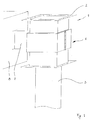
- a device for drying a layer of lacquer applied to a galvanized steel strip 3 includes a length of approx. 10 to 15 meters (depending on the belt speed) vertically oriented channel, of which only a single one for the sake of clarity Channel segment 1 is shown.
- the channel consists of a large number of such channel segments 1, which are arranged one behind the other in the longitudinal direction of the channel and by means of each two flanges 2 arranged on opposite end faces and suitable screws are interconnected.
- Through the channel formed in this way is in its longitudinal direction the paint-coated steel strip 3 by means of known and not in the drawing shown guide and drive devices performed.
- the steel strip 3 painted in front of the device is coated with a moist and liquid coating introduced at the lower end of the channel and leaves the channel at the top Front with dried and hardened paint.
- the cross section of the channel shown in Figure 2 is rectangular and has a clear Width 4 of about 200 mm, and a clear length 5 of about 1600 mm.
- the width of the steel belt 3 is approximately 1500 mm.
- Each channel segment 1 is surrounded by a closed coil 6, which in cross section is also rectangular and consists of a copper sheet.
- the coil 6 only has a single turn and is connected to an inverter 8 via connectors 7, through which the coil 6 with a high-frequency voltage with a frequency of about 100 kHz is supplied.
- the coil 6 is in a central plane running parallel to the longitudinal axis of the channel divisible to expand the coil 6 and the enclosed channel segment if necessary easy to replace or repair.
- the coil 6 is equidistant from the walls 8 of the channel segment 1 arranged. Between the one on the inside with a plastic coating Provided steel sheet existing channel walls 8 and the coil 6 is located there is an insulating material 9 that an undesirable heat loss from the channel on the Walls 8 largely prevented. On the outside of the coil 6 are meandering running pipelines and not shown in Figure 1 for the sake of clarity 10, which are traversed by a cooling liquid and inevitable for removal provide heat generated in the coil 6.
- the possibility of using the walls 8 specifically with the aid of the coil is particularly advantageous 6 generated magnetic field to heat up after a period of inactivity Drying device to be put back into operation.
- the to start the device required minimum temperature of the walls 8, each after the solvent emerging from the varnish is approx. 150 ° C, by just one Operation of the coil 6 can be achieved without - as in the prior art - over a longer period Period of preheated air is passed through the duct.
- the time until The process according to the invention thus makes it possible to restart production shortens and the security that a certain minimum temperature at all locations of the walls 8 prevails, increased.
Landscapes
- Engineering & Computer Science (AREA)
- Microbiology (AREA)
- General Engineering & Computer Science (AREA)
- Mechanical Engineering (AREA)
- Life Sciences & Earth Sciences (AREA)
- Molecular Biology (AREA)
- Biotechnology (AREA)
- Biomedical Technology (AREA)
- Physics & Mathematics (AREA)
- Health & Medical Sciences (AREA)
- Electromagnetism (AREA)
- Textile Engineering (AREA)
- Coating Apparatus (AREA)
- Drying Of Solid Materials (AREA)
- Application Of Or Painting With Fluid Materials (AREA)
- General Induction Heating (AREA)
- Resistance Heating (AREA)
Abstract
Description
- Fig. 1
- eine perspektivische Darstellung eines Kanalabschnitts und
- Fig. 2
- einen Querschnitt durch den Kanal gemäß Figur 1.
Claims (8)
- Verfahren zum Trockenen und/oder Einbrennen einer auf ein metallisches Band aufge-brachten Beschichtung, wobei das Band kontinuierlich durch einen an zwei Stirnseiten offenen und ansonsten geschlossenen Kanal aus plattenförmigen Wandungen hindurchgeführt und während des Durchlaufs erhitzt wird, wodurch die Beschichtung trocknet und/oder einbrennt, wobei in dem Band Wirbelströme durch ein Magnetfeld induziert werden, das mittels mindestens einer Spule erzeugt wird, die koaxial zu dem Kanal ausgerichtet ist und diesen umschließt, dadurch gekennzeichnet, daß der Anteil der von der Spule abgegebenen magnetischen Leistung, die von den Wandungen des Kanals aufgenommen wird und dort zu einer Erhitzung führt, mindestens 3 % beträgt.
- Verfahren nach Anspruch 1, dadurch gekennzeichnet, daß der Anteil, der von der Spule abgegebenen magnetischen Leistung die von den Wandungen des Kanals aufgenommen wird und dort zu einer Erhitzung führt, mindestens 5 % beträgt.
- Verfahren nach Anspruch 1 oder 2, dadurch gekennzeichnet, daß der Anteil, der von der Spule abgegebenen magnetischen Leistung die von den Wandungen des Kanals aufgenommen wird und dort zu einer Erhitzung führt, mindestens 7 % beträgt.
- Verfahren nach dem Oberbegriff des Anspruchs 1, dadurch gekennzeichnet, daß die Wandung des Kanals mittels einer elektrischen Wiederstandsheizung erhitzt wird.
- Verfahren nach einem der Ansprüche 1 bis 4, dadurch gekennzeichnet, daß in der Aufheizphase bei stillstehendem Band die Aufheizung der Wandungen des Kanals ausschließlich mittels einer Induktion von Wirbelströmen in den Wandungen mit Hilfe der mindestens einen Spule oder ausschließlich mittels einer elektrischen Widerstandsheizung erfolgt.
- Vorrichtung zum Trocknen und/oder Einbrennen einer auf ein metallisches Band aufgebrachten Beschichtung, mit einem aus plattenförmigen Wandungen bestehenden, stirnseitig offenen und ansonsten geschlossen ausgebildeten Kanal, durch den das Band mittels Führungs- und Antriebseinrichtungen in Längsrichtung des Kanals hindurchführbar ist, wobei das Band während des Durchlaufs mittels einer Heizeinrichtung auf eine Trocknungs- und/oder Einbrenntemperatur aufheizbar ist und die Heizeinrichtung mindestens eine Spule aufweist, die den Kanal umschließt und ein Magnetfeld im Innern des Kanals erzeugt, durch das in dem Band Wirbelströme induzierbar sind, wodurch das Band aufheizbar ist, dadurch gekennzeichnet, daß die Wandungen des Kanals mit einer elektrischen Widerstandsheizung versehen sind.
- Vorrichtung nach Anspruch 6, dadurch gekennzeichnet, daß die Widerstandsheizung an der Außenseite der Wandungen des Kanals angeordnet ist.
- Vorrichtung nach Anspruch 7, dadurch gekennzeichnet, daß die Widerstandsheizung als Widerstandsgewebe ausgebildet ist, das flächig an den Wandungen befestigt ist.
Priority Applications (1)
| Application Number | Priority Date | Filing Date | Title |
|---|---|---|---|
| EP04028213A EP1508383A3 (de) | 2001-06-20 | 2002-06-12 | Verfahren und Vorrichtung zum Trocknen und/oder Einbrennen einer auf ein metallisches Band aufgebrachte Beschichtung |
Applications Claiming Priority (2)
| Application Number | Priority Date | Filing Date | Title |
|---|---|---|---|
| DE10130342A DE10130342C1 (de) | 2001-06-20 | 2001-06-20 | Verfahren und Vorrichtung zum Trocknen und/oder Einbrennen einer auf ein metallisches Band aufgebrachten Beschichtung |
| DE10130342 | 2001-06-20 |
Related Child Applications (1)
| Application Number | Title | Priority Date | Filing Date |
|---|---|---|---|
| EP04028213A Division EP1508383A3 (de) | 2001-06-20 | 2002-06-12 | Verfahren und Vorrichtung zum Trocknen und/oder Einbrennen einer auf ein metallisches Band aufgebrachte Beschichtung |
Publications (3)
| Publication Number | Publication Date |
|---|---|
| EP1270088A2 true EP1270088A2 (de) | 2003-01-02 |
| EP1270088A3 EP1270088A3 (de) | 2004-01-02 |
| EP1270088B1 EP1270088B1 (de) | 2007-07-18 |
Family
ID=7689204
Family Applications (2)
| Application Number | Title | Priority Date | Filing Date |
|---|---|---|---|
| EP02012977A Expired - Lifetime EP1270088B1 (de) | 2001-06-20 | 2002-06-12 | Verfahren zum Trocknen und/oder Einbrennen einer auf ein metallisches Band aufgebrachten Beschichtung |
| EP04028213A Withdrawn EP1508383A3 (de) | 2001-06-20 | 2002-06-12 | Verfahren und Vorrichtung zum Trocknen und/oder Einbrennen einer auf ein metallisches Band aufgebrachte Beschichtung |
Family Applications After (1)
| Application Number | Title | Priority Date | Filing Date |
|---|---|---|---|
| EP04028213A Withdrawn EP1508383A3 (de) | 2001-06-20 | 2002-06-12 | Verfahren und Vorrichtung zum Trocknen und/oder Einbrennen einer auf ein metallisches Band aufgebrachte Beschichtung |
Country Status (4)
| Country | Link |
|---|---|
| EP (2) | EP1270088B1 (de) |
| AT (1) | ATE367214T1 (de) |
| DE (2) | DE10130342C1 (de) |
| ES (1) | ES2289030T3 (de) |
Families Citing this family (2)
| Publication number | Priority date | Publication date | Assignee | Title |
|---|---|---|---|---|
| DE102008015658A1 (de) * | 2008-03-25 | 2009-11-12 | Gesellschaft für aero- und thermodynamische Verfahrenstechnik mbH | Vorrichtung und Verfahren zur Erwärmung von Metallbändern |
| US9789514B2 (en) | 2008-05-08 | 2017-10-17 | Primetals Technologies France SAS | Method of drying and/or curing an organic coating on a continuously running metal strip, and device for implementing this method |
Family Cites Families (7)
| Publication number | Priority date | Publication date | Assignee | Title |
|---|---|---|---|---|
| GB788900A (en) * | 1954-01-19 | 1958-01-08 | Isopad Ltd | Improvements in or relating to the electrical heating of vessels and pipes |
| FR2391849A1 (fr) * | 1977-05-25 | 1978-12-22 | Profil Sa Ind Financ Le | Procede et installation de fabrication d'une baguette composite |
| US4370357A (en) * | 1981-03-11 | 1983-01-25 | Cleveland Gear Company | Process of continuous metal coating |
| CA1309755C (en) * | 1987-03-30 | 1992-11-03 | Hiroyoshi Nozaki | Method of and apparatus for baking coating layer |
| EP0509374B1 (de) * | 1991-04-18 | 1998-03-04 | Alltrista Corporation | Verfahren und Vorrichtung zur Trocknung und Härtung einer Beschichtung eines metallischen Substrats |
| FR2734501B1 (fr) * | 1995-05-23 | 1997-07-04 | Stein Heurtey | Procede et dispositif de revetement de bandes metalliques |
| DE19626209A1 (de) * | 1996-06-29 | 1998-01-08 | Ema Elektro Maschinen Schultze | Vorrichtung und Verfahren zum Beschichten eines Werkstücks |
-
2001
- 2001-06-20 DE DE10130342A patent/DE10130342C1/de not_active Expired - Fee Related
-
2002
- 2002-06-12 DE DE50210484T patent/DE50210484D1/de not_active Expired - Fee Related
- 2002-06-12 EP EP02012977A patent/EP1270088B1/de not_active Expired - Lifetime
- 2002-06-12 EP EP04028213A patent/EP1508383A3/de not_active Withdrawn
- 2002-06-12 AT AT02012977T patent/ATE367214T1/de not_active IP Right Cessation
- 2002-06-12 ES ES02012977T patent/ES2289030T3/es not_active Expired - Lifetime
Also Published As
| Publication number | Publication date |
|---|---|
| EP1508383A2 (de) | 2005-02-23 |
| EP1508383A3 (de) | 2006-03-29 |
| EP1508383A9 (de) | 2006-08-02 |
| EP1270088A3 (de) | 2004-01-02 |
| DE10130342C1 (de) | 2003-02-06 |
| EP1270088B1 (de) | 2007-07-18 |
| DE50210484D1 (de) | 2007-08-30 |
| ES2289030T3 (es) | 2008-02-01 |
| ATE367214T1 (de) | 2007-08-15 |
Similar Documents
| Publication | Publication Date | Title |
|---|---|---|
| EP2726802A1 (de) | VERFAHREN ZUM ERWÄRMEN EINES FORMBAUTEILS FÜR EIN ANSCHLIEßENDES PRESSHÄRTEN SOWIE DURCHLAUFOFEN ZUM BEREICHSWEISEN ERWÄRMEN EINES AUF EINE VORGEGEBENE TEMPERATUR VORGEWÄRMTEN FORMBAUTEILS AUF EINE HÖHERE TEMPERATUR | |
| DE69708482T2 (de) | Durchlaufglühverfahren von Metallband in verschiedenen Schutzgasen und Vorrichtung | |
| EP3710234B1 (de) | Vorrichtung zum thermischen verschweissen von kunststoffteilen sowie anordnung enthaltend eine solche vorrichtung | |
| AT522345A1 (de) | Heizungsvorrichtung zum induktiven Erhitzen eines Flachstahlstreifens in einem Warmwalzwerk | |
| EP2274475B1 (de) | Beheizte prägewalze | |
| WO2014191142A1 (de) | TRANSPORTVORRICHTUNG FÜR HEIßE, DÜNNWANDIGE STAHLTEILE | |
| DE2637646B2 (de) | Anwärmofen | |
| DE202017007313U1 (de) | Rotierender-Magnet-Heizinduktion | |
| AT509596B1 (de) | Verfahren zum erwärmen eines formbauteils für ein anschliessendes presshärten sowie durchlaufofen zum bereichsweisen erwärmen eines auf eine vorgegebene temperatur vorgewärmten formbauteils auf eine höhere temperatur | |
| DE102015112293A1 (de) | Verfahren und Vorrichtung zur planheitsadaptiven Temperaturänderung von Metallbändern | |
| EP2531624B1 (de) | Vorrichtung und verfahren zum wärmebehandeln von stahldrähten | |
| DE102016114841A1 (de) | Chargenofen für Glühgut und Verfahren zur Wärmebehandlung | |
| WO2019141682A1 (de) | Durchlaufofen für aluminiumbänder | |
| DE102009050879B3 (de) | Verfahren und Vorrichtung zur Erwärmung von Platinen | |
| EP2930723B1 (de) | Verfahren und vorrichtung zur verarbeitung eines drahtes | |
| DE3034528C2 (de) | Verfahren und Vorrichtung zum Abkühlen von warmgewalztem Draht | |
| DE3118830A1 (de) | "anlage zur lackdrahtherstellung im inlineverfahren" | |
| EP1270088A2 (de) | Verfahren und Vorrichtung zum Trocknen und/oder Einbrennen einer auf ein metallisches Band aufgebrachten Beschichtung | |
| DE1652395B2 (de) | Verfahren und Einrichtung zum kontinuierlichen Emaillackieren von Draht | |
| DE1808231A1 (de) | Verfahren und Vorrichtung zum UEberziehen von Blechstreifen od.dgl.mit warmhaertender Farbe | |
| DE2628657C2 (de) | Temperatur-Ausgleichsofen für im Durchlaufverfahren zu erwärmende metallische Werkstücke | |
| DE2556057C2 (de) | Verfahren und Vorrichtung zum Erwärmen von Metallbändern, insbesondere Nichteisen-Metallbändern | |
| DE10245004A1 (de) | Verfahren und Anordnung zur thermischen Behandlung eines Werkstücks | |
| DE102011107561A1 (de) | Walzprofiliervorrichtung zur Herstellung eines partiell gehärteten Profilformteils | |
| WO2022263614A2 (de) | Trocknungsvorrichtung zur trocknung von behältereinheiten und verfahren |
Legal Events
| Date | Code | Title | Description |
|---|---|---|---|
| PUAI | Public reference made under article 153(3) epc to a published international application that has entered the european phase |
Free format text: ORIGINAL CODE: 0009012 |
|
| AK | Designated contracting states |
Kind code of ref document: A2 Designated state(s): AT BE CH CY DE DK ES FI FR GB GR IE IT LI LU MC NL PT SE TR |
|
| AX | Request for extension of the european patent |
Free format text: AL;LT;LV;MK;RO;SI |
|
| PUAL | Search report despatched |
Free format text: ORIGINAL CODE: 0009013 |
|
| AK | Designated contracting states |
Kind code of ref document: A3 Designated state(s): AT BE CH CY DE DK ES FI FR GB GR IE IT LI LU MC NL PT SE TR |
|
| AX | Request for extension of the european patent |
Extension state: AL LT LV MK RO SI |
|
| RIC1 | Information provided on ipc code assigned before grant |
Ipc: 7F 26B 3/34 B Ipc: 7B 05D 3/02 A |
|
| 17P | Request for examination filed |
Effective date: 20040401 |
|
| AKX | Designation fees paid |
Designated state(s): AT BE CH CY DE DK ES FI FR GB GR IE IT LI LU MC NL PT SE TR |
|
| 17Q | First examination report despatched |
Effective date: 20040923 |
|
| GRAP | Despatch of communication of intention to grant a patent |
Free format text: ORIGINAL CODE: EPIDOSNIGR1 |
|
| RTI1 | Title (correction) |
Free format text: PROCESS FOR DRYING AND/OR CURING A COATING DEPOSITED ON A METALLIC SHEET |
|
| GRAS | Grant fee paid |
Free format text: ORIGINAL CODE: EPIDOSNIGR3 |
|
| GRAA | (expected) grant |
Free format text: ORIGINAL CODE: 0009210 |
|
| AK | Designated contracting states |
Kind code of ref document: B1 Designated state(s): AT BE CH CY DE DK ES FI FR GB GR IE IT LI LU MC NL PT SE TR |
|
| REG | Reference to a national code |
Ref country code: GB Ref legal event code: FG4D Free format text: NOT ENGLISH |
|
| REG | Reference to a national code |
Ref country code: CH Ref legal event code: EP |
|
| REF | Corresponds to: |
Ref document number: 50210484 Country of ref document: DE Date of ref document: 20070830 Kind code of ref document: P |
|
| REG | Reference to a national code |
Ref country code: IE Ref legal event code: FG4D Free format text: LANGUAGE OF EP DOCUMENT: GERMAN |
|
| GBT | Gb: translation of ep patent filed (gb section 77(6)(a)/1977) |
Effective date: 20070831 |
|
| ET | Fr: translation filed | ||
| PG25 | Lapsed in a contracting state [announced via postgrant information from national office to epo] |
Ref country code: FI Free format text: LAPSE BECAUSE OF FAILURE TO SUBMIT A TRANSLATION OF THE DESCRIPTION OR TO PAY THE FEE WITHIN THE PRESCRIBED TIME-LIMIT Effective date: 20070718 Ref country code: PT Free format text: LAPSE BECAUSE OF FAILURE TO SUBMIT A TRANSLATION OF THE DESCRIPTION OR TO PAY THE FEE WITHIN THE PRESCRIBED TIME-LIMIT Effective date: 20071218 |
|
| REG | Reference to a national code |
Ref country code: ES Ref legal event code: FG2A Ref document number: 2289030 Country of ref document: ES Kind code of ref document: T3 |
|
| REG | Reference to a national code |
Ref country code: IE Ref legal event code: FD4D |
|
| PG25 | Lapsed in a contracting state [announced via postgrant information from national office to epo] |
Ref country code: GR Free format text: LAPSE BECAUSE OF FAILURE TO SUBMIT A TRANSLATION OF THE DESCRIPTION OR TO PAY THE FEE WITHIN THE PRESCRIBED TIME-LIMIT Effective date: 20071019 Ref country code: DK Free format text: LAPSE BECAUSE OF FAILURE TO SUBMIT A TRANSLATION OF THE DESCRIPTION OR TO PAY THE FEE WITHIN THE PRESCRIBED TIME-LIMIT Effective date: 20070718 |
|
| PLBE | No opposition filed within time limit |
Free format text: ORIGINAL CODE: 0009261 |
|
| STAA | Information on the status of an ep patent application or granted ep patent |
Free format text: STATUS: NO OPPOSITION FILED WITHIN TIME LIMIT |
|
| PG25 | Lapsed in a contracting state [announced via postgrant information from national office to epo] |
Ref country code: IE Free format text: LAPSE BECAUSE OF FAILURE TO SUBMIT A TRANSLATION OF THE DESCRIPTION OR TO PAY THE FEE WITHIN THE PRESCRIBED TIME-LIMIT Effective date: 20070718 |
|
| 26N | No opposition filed |
Effective date: 20080421 |
|
| PG25 | Lapsed in a contracting state [announced via postgrant information from national office to epo] |
Ref country code: SE Free format text: LAPSE BECAUSE OF FAILURE TO SUBMIT A TRANSLATION OF THE DESCRIPTION OR TO PAY THE FEE WITHIN THE PRESCRIBED TIME-LIMIT Effective date: 20071018 |
|
| PGFP | Annual fee paid to national office [announced via postgrant information from national office to epo] |
Ref country code: LU Payment date: 20080618 Year of fee payment: 7 |
|
| PGFP | Annual fee paid to national office [announced via postgrant information from national office to epo] |
Ref country code: AT Payment date: 20080612 Year of fee payment: 7 |
|
| PGFP | Annual fee paid to national office [announced via postgrant information from national office to epo] |
Ref country code: DE Payment date: 20080630 Year of fee payment: 7 Ref country code: NL Payment date: 20080603 Year of fee payment: 7 |
|
| PGFP | Annual fee paid to national office [announced via postgrant information from national office to epo] |
Ref country code: GB Payment date: 20080618 Year of fee payment: 7 |
|
| PG25 | Lapsed in a contracting state [announced via postgrant information from national office to epo] |
Ref country code: MC Free format text: LAPSE BECAUSE OF NON-PAYMENT OF DUE FEES Effective date: 20080630 |
|
| REG | Reference to a national code |
Ref country code: CH Ref legal event code: PL |
|
| PG25 | Lapsed in a contracting state [announced via postgrant information from national office to epo] |
Ref country code: LI Free format text: LAPSE BECAUSE OF NON-PAYMENT OF DUE FEES Effective date: 20080630 Ref country code: CH Free format text: LAPSE BECAUSE OF NON-PAYMENT OF DUE FEES Effective date: 20080630 |
|
| PG25 | Lapsed in a contracting state [announced via postgrant information from national office to epo] |
Ref country code: CY Free format text: LAPSE BECAUSE OF FAILURE TO SUBMIT A TRANSLATION OF THE DESCRIPTION OR TO PAY THE FEE WITHIN THE PRESCRIBED TIME-LIMIT Effective date: 20070718 |
|
| PGFP | Annual fee paid to national office [announced via postgrant information from national office to epo] |
Ref country code: IT Payment date: 20090620 Year of fee payment: 8 |
|
| PGFP | Annual fee paid to national office [announced via postgrant information from national office to epo] |
Ref country code: BE Payment date: 20090619 Year of fee payment: 8 |
|
| PGFP | Annual fee paid to national office [announced via postgrant information from national office to epo] |
Ref country code: ES Payment date: 20090709 Year of fee payment: 8 |
|
| GBPC | Gb: european patent ceased through non-payment of renewal fee |
Effective date: 20090612 |
|
| NLV4 | Nl: lapsed or anulled due to non-payment of the annual fee |
Effective date: 20100101 |
|
| PG25 | Lapsed in a contracting state [announced via postgrant information from national office to epo] |
Ref country code: GB Free format text: LAPSE BECAUSE OF NON-PAYMENT OF DUE FEES Effective date: 20090612 |
|
| PG25 | Lapsed in a contracting state [announced via postgrant information from national office to epo] |
Ref country code: DE Free format text: LAPSE BECAUSE OF NON-PAYMENT OF DUE FEES Effective date: 20100101 Ref country code: AT Free format text: LAPSE BECAUSE OF NON-PAYMENT OF DUE FEES Effective date: 20090612 |
|
| PG25 | Lapsed in a contracting state [announced via postgrant information from national office to epo] |
Ref country code: NL Free format text: LAPSE BECAUSE OF NON-PAYMENT OF DUE FEES Effective date: 20100101 |
|
| PG25 | Lapsed in a contracting state [announced via postgrant information from national office to epo] |
Ref country code: TR Free format text: LAPSE BECAUSE OF FAILURE TO SUBMIT A TRANSLATION OF THE DESCRIPTION OR TO PAY THE FEE WITHIN THE PRESCRIBED TIME-LIMIT Effective date: 20070718 |
|
| BERE | Be: lapsed |
Owner name: INDUCTOTHERM COATING EQUIPMENT S.A. Effective date: 20100630 |
|
| REG | Reference to a national code |
Ref country code: FR Ref legal event code: ST Effective date: 20110228 |
|
| PG25 | Lapsed in a contracting state [announced via postgrant information from national office to epo] |
Ref country code: IT Free format text: LAPSE BECAUSE OF NON-PAYMENT OF DUE FEES Effective date: 20100612 |
|
| PG25 | Lapsed in a contracting state [announced via postgrant information from national office to epo] |
Ref country code: LU Free format text: LAPSE BECAUSE OF NON-PAYMENT OF DUE FEES Effective date: 20090612 |
|
| PG25 | Lapsed in a contracting state [announced via postgrant information from national office to epo] |
Ref country code: FR Free format text: LAPSE BECAUSE OF NON-PAYMENT OF DUE FEES Effective date: 20100630 |
|
| PG25 | Lapsed in a contracting state [announced via postgrant information from national office to epo] |
Ref country code: BE Free format text: LAPSE BECAUSE OF NON-PAYMENT OF DUE FEES Effective date: 20100630 |
|
| REG | Reference to a national code |
Ref country code: ES Ref legal event code: FD2A Effective date: 20110714 |
|
| PG25 | Lapsed in a contracting state [announced via postgrant information from national office to epo] |
Ref country code: ES Free format text: LAPSE BECAUSE OF NON-PAYMENT OF DUE FEES Effective date: 20110704 |
|
| PG25 | Lapsed in a contracting state [announced via postgrant information from national office to epo] |
Ref country code: ES Free format text: LAPSE BECAUSE OF NON-PAYMENT OF DUE FEES Effective date: 20100613 |
|
| PGFP | Annual fee paid to national office [announced via postgrant information from national office to epo] |
Ref country code: FR Payment date: 20090611 Year of fee payment: 8 |