EP1269825A1 - Support wheel arrangement for an agricultural working machine - Google Patents
Support wheel arrangement for an agricultural working machine Download PDFInfo
- Publication number
- EP1269825A1 EP1269825A1 EP02013051A EP02013051A EP1269825A1 EP 1269825 A1 EP1269825 A1 EP 1269825A1 EP 02013051 A EP02013051 A EP 02013051A EP 02013051 A EP02013051 A EP 02013051A EP 1269825 A1 EP1269825 A1 EP 1269825A1
- Authority
- EP
- European Patent Office
- Prior art keywords
- support
- harvesting machine
- load
- agricultural
- agricultural harvesting
- Prior art date
- Legal status (The legal status is an assumption and is not a legal conclusion. Google has not performed a legal analysis and makes no representation as to the accuracy of the status listed.)
- Granted
Links
- 238000003306 harvesting Methods 0.000 claims abstract description 36
- 238000000034 method Methods 0.000 claims description 9
- 230000006978 adaptation Effects 0.000 claims description 4
- 230000001419 dependent effect Effects 0.000 claims description 3
- 230000001105 regulatory effect Effects 0.000 claims 1
- 230000000087 stabilizing effect Effects 0.000 abstract 1
- 230000008878 coupling Effects 0.000 description 6
- 238000010168 coupling process Methods 0.000 description 6
- 238000005859 coupling reaction Methods 0.000 description 6
- 230000007246 mechanism Effects 0.000 description 4
- 241001124569 Lycaenidae Species 0.000 description 2
- 230000008901 benefit Effects 0.000 description 2
- 230000008859 change Effects 0.000 description 2
- 230000007423 decrease Effects 0.000 description 2
- 230000005484 gravity Effects 0.000 description 2
- 230000033228 biological regulation Effects 0.000 description 1
- 230000015572 biosynthetic process Effects 0.000 description 1
- 238000005516 engineering process Methods 0.000 description 1
- 239000004459 forage Substances 0.000 description 1
- 230000035939 shock Effects 0.000 description 1
- 239000003381 stabilizer Substances 0.000 description 1
Images


Classifications
-
- A—HUMAN NECESSITIES
- A01—AGRICULTURE; FORESTRY; ANIMAL HUSBANDRY; HUNTING; TRAPPING; FISHING
- A01D—HARVESTING; MOWING
- A01D41/00—Combines, i.e. harvesters or mowers combined with threshing devices
- A01D41/12—Details of combines
-
- A—HUMAN NECESSITIES
- A01—AGRICULTURE; FORESTRY; ANIMAL HUSBANDRY; HUNTING; TRAPPING; FISHING
- A01D—HARVESTING; MOWING
- A01D67/00—Undercarriages or frames specially adapted for harvesters or mowers; Mechanisms for adjusting the frame; Platforms
-
- B—PERFORMING OPERATIONS; TRANSPORTING
- B60—VEHICLES IN GENERAL
- B60G—VEHICLE SUSPENSION ARRANGEMENTS
- B60G2300/00—Indexing codes relating to the type of vehicle
- B60G2300/08—Agricultural vehicles
-
- B—PERFORMING OPERATIONS; TRANSPORTING
- B60—VEHICLES IN GENERAL
- B60G—VEHICLE SUSPENSION ARRANGEMENTS
- B60G2400/00—Indexing codes relating to detected, measured or calculated conditions or factors
- B60G2400/60—Load
- B60G2400/61—Load distribution
Definitions
- the invention relates to a method for operating a support wheel arrangement for an agricultural Working machine according to the preamble of claim 1 and a device to carry out this method according to the preamble of claim 6.
- the invention is therefore based on the object, a support wheel arrangement for agricultural To further develop work machines so that the disadvantages of the state described the technology can be avoided and a permanent contact of the jockey wheel arrangement with the floor is guaranteed.
- the object is achieved by a method for operating a jockey wheel arrangement for agricultural harvesters with the characterizing features of the claim 1 and a device for performing this method according to the characterizing Features of claim 6 solved.
- the support load of the at least one in the area between the agricultural harvester and the support wheel adapted to its associated agricultural implement is adjustable, it is ensured that the at least one support wheel is a permanent one Relief of the axes of the agricultural harvester realized. Above all, this has the advantage that the axles of the carrier vehicle have to be supported due to the smaller number Loads can be manufactured less material-intensive and therefore more cost-effectively.
- a particularly advantageous development of the invention results when the agricultural Harvester is assigned a variety of support wheels and the support loads the large number of support wheels can be set independently of one another. In addition to another Relief of the carrier vehicle axles enables the arrangement of a large number of support wheels ensuring low ground pressures.
- the adjustability of the drawbar load of the at least a jockey wheel can also be used to control the ground contact pressure to adjust the agricultural harvesting machine to the adapted header.
- the drawbar load of the at least one support wheel as a function of the load shares can be set.
- the drawbar load distribution can be designed to be dynamically adaptable.
- the adjustability of the drawbar load of the at least achieved a support wheel in that the at least one support wheel essentially one in the vertical direction relative movement to the receiving device and / or can run to the agricultural harvester, this vertical relative movement in the simplest case is achieved in that the at least one support wheel essentially in the vertical direction extending lifting cylinder is assigned, which Jockey wheel connects to the receiving device and / or the agricultural harvester.
- the permanent contact with the floor can be achieved by the at least a jockey wheel can be achieved by the vertical movement of the jockey wheel Realizing lifting cylinders in operative connection with the lifting cylinder or cylinders of the receiving device stands, so that the lifting device automatically to one Lowering the at least one support wheel leads and vice versa the lowering of the receiving device the automatic lifting of the at least one support wheel entails.
- Drive axle and / or the steering axle assigned to known load-sensing transducers be a load-dependent output signal for the regulation of the Generate hydraulic pressure of the lifting cylinder of the at least one support wheel.
- a permanent adjustment of the at least Suppressing a load share of a support wheel can be advantageous in another Formation of the invention of the lifting cylinder of the at least one support wheel lockable be so that the support wheel is no longer able to move relative to the receiving device perform.
- the ratio of the support loads in the electronic Billing unit to be adjustable.
- this load distribution can be achieved in that the piston area ratio the lifting cylinder of the receiving device and the lifting cylinder of the at least one support wheel the load distribution ratio between the support load of the at least a support wheel and the one or more lifting cylinders of the receiving device support load transferred to the agricultural harvester.
- the lifting cylinder of the at least one support wheel takes an approximately vertical position.
- the at least one support wheel even when the agricultural implement is not adapted Moved on the ground, can be between cradle and agricultural Work machine a pull rod interposed, the at least one support wheel always forces towards the ground.
- a support wheel in an advantageous development of the invention is steerable his.
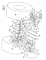
- FIG. 1 shows an agricultural harvesting machine 1 designed as a combine harvester 2, in its front area a pivot axis pointing transverse to the direction of travel FR 3 receives, which in turn the receiving device designed as a known inclined conveyor 4 5 pivots in the vertical direction.
- the receiving device designed as a known inclined conveyor 4 5 pivots in the vertical direction.
- Inclined conveyor 4 holding flanges 6 are formed, the ends of a transverse to the direction FR pointing axis 7 pivotally the front ends of the piston rods 8 of lifting cylinders Record 9.
- the lifting cylinders 9 are also transverse to Travel direction FR pointing axes 10 pivoting on the agricultural harvester 1 arranged.
- the piston rods 8 By pressurizing or relieving the pressure on the lifting cylinders 9, the piston rods 8 move out of the cylinders 11 of the lifting cylinders 9 or plunge into them so that the receiving device 5 pivots vertically Executes direction about the axis 3 arranged on the carrier vehicle 1.
- the lifting cylinders 9 also have the task to support the receiving device 5 on the carrier vehicle 1.
- the receiving device 5 is in a manner known per se and therefore not described in detail
- the receiving device 5 in the area between the grain cutter 12 and the front axle 14 of the combine 2 support wheels on both sides 15 assigned.
- the wheel axle 16 of each support wheel 15 is enclosed by a hub 17, a receiving flange at its inside, in the area of the support wheels 15 18 is integrally formed, the one in the simplest case pointing in the vertical direction is executed as axially secured bolt 19 pivot axis 20.
- the rim area 21 of the support wheels 15 also passes through the vertical pivot axis 20 through a guide eye 22, which is attached at the other end to at least one first support arm 23.
- each support wheel 15 such a support arm 23, each Support arm 23 at its end receiving the respective support wheel 15 of any shape Headpiece 24 is formed, an angle profile carrier 25 with the carrier vehicle side welded in the direction of the front axle 14 of the carrier vehicle 1 enlarging cross section is.
- the front axle 14 of the agricultural machine 1 are on the front Assigned holding flanges 26, which in the simplest case are designed as axially secured bolts 27 axles 28 pointing transversely to the direction of travel FR.
- the distance between adjacent retaining flanges 26 of the flange-like extensions 29 Angular section carrier 25 penetrates in such a way that the respective bolt 27 is assigned to it Angle profile carrier 25 pivots in the vertical direction.
- the at least one first support arm 23 of a support frame 30 can be pivoted with it the agricultural harvester 1 connected in the region of its front axle 14.
- the head piece 24 of the first support arm 23 is on the opposite support wheel 15 Formed a retaining tab 31.
- the respective retaining tab 31 takes the front End of the piston rod 32 of a lifting cylinder 33 pointing transversely to the direction of travel FR Axis 34 pivotable on, the cylinder end of the lifting cylinder 33 by one axis 35 also arranged transversely to the direction of travel FR can be pivoted on the receiving device 5 of the agricultural harvester 1 is attached.
- the respective one Lift cylinder 33 a further support arm 36 of the support frame 30, the at least one Jockey wheel 15 pivotable with the cradle 5 of the agricultural Harvester 1 connects.
- each of the support wheels 15 is one of one first support arm 25 and at least one additional support arm 36 existing support frame 30 with both the agricultural harvesting machine 1 and the receiving device 5 connected. It is within the scope of the invention that the two parts in the embodiment executed support frame 30 is designed in one piece and this one-piece support frame 30 over one or more pivot axes 28 arranged transversely to the direction of travel FR the agricultural harvester 1 is arranged. It would also be conceivable that the Recording device 5 via only one lifting cylinder 9 or any number of lifting cylinders 9 is supported on the agricultural harvester 1.
- the second support arms 36 as lifting cylinders 33, it is ensured that the Assignment of the support wheels 15 to the frame 5 changed in the vertical direction can be so that the support wheels 15 regardless of the position of the receiving device 5th can always touch the floor 36.
- support load F1 of the at least one support wheel 15 to be supported is adjustable. It is in the Within the scope of the invention, to assign a plurality of support wheels 15 to the receiving device 5, at least some of which have adjustable support loads F1 by means of lifting cylinders 33 transfer the floor 37. A particularly advantageous one to be described in more detail below Execution of the support wheels 15 adjustable in their support load F1 is then achieved if this adjustability of the vertical load F1 also controls the contact pressure p des agricultural implement 13 on the floor 37 allows.
- the lifting cylinder 33 of the at least one support wheel 15 and the one or more lifting cylinders 9 of the receiving device 5 are designed as single-acting lifting cylinders 9, 33, the pressure chambers 39, 40 of the lifting cylinders 9, 33 being connected to one another via a system line 38 are connected.
- the system line 38 is also connected to at least one pressure limiting valve 41, which limits the pressure in the system line 38 and connects the system line to the tank 42 when the pressure threshold value p e that can be set at the pressure limiting valve 41 is exceeded, so that part of the energy-transmitting medium can flow into the tank 42 ,
- the pressure relief valve 41 connected in parallel can also be replaced by a pressure relief valve 41a connected in series with the at least one lifting cylinder 9 of the receiving device 5, which separates the lifting cylinder 9 of the receiving device 5 from the system line 38 as soon as the line pressure reaches the Reached set value p e .
- the system line 38 is also with the in itself known manner in the agricultural harvester 1 integrated pump P or Tank T connected. Pressurizing system line 38 causes the piston rods 8, 32 are pushed out of the respective lifting cylinders 9, 33. there the receiving device 5 performs a pivoting movement about its top, on the carrier vehicle 1 arranged pivot axis 3 in a position remote from the ground. Moved at the same time that of the other lifting cylinder 33 is vertically movable on the receiving device 5 arranged at least one support wheel 15 in the direction of the ground, so that it is always guaranteed that the at least one support wheel 15 is in contact with the floor 37.
- the coupled lifting cylinders 9, 33 are single-acting, that leads gravity-related lowering of the receiving device 5 at the same time also gravity-driven retraction of the at least one support wheel 15 receiving vertically movable Lift cylinder 33.
- the ratio between the support load to be transmitted by the at least one support wheel 15 F1 and the to the wheels 44 of the adjacent front axle 14 by means of the lifting cylinder or cylinders 9 support load F to be transmitted is always constant, this ratio being the ratio corresponds to the piston surfaces A1, A2 of the mutually coupled lifting cylinders 9, 33.
- the single-acting design according to FIG Lift cylinders 9, 33 can also be double-acting according to Figure 4.
- the support wheels 15 can also rotate about the vertical pivot axis 20 be pivotable, the bolt 19 forming the pivot axis 20 on the top is gripped by a steering lever 52, one end of which points in the vertical direction Stud 53 is assigned.
- the support arm 23 receiving the respective support wheel 15 has on the front axle 14 of the agricultural harvester 1 assigned End via a vertical stud 54 pointing to the vertical stud 54 an angle lever 55 is pivotally arranged, which in turn a plurality of studs 56, 57, 58 are assigned in a rotationally fixed manner.
- a first coupling rod 59 connects the stud bolt 53 of the steering lever 52 can be pivoted with one arranged on the angle lever 55 Stud 56, with the coupling rod 59 above and in the area of the angle section support 25 of the respective support arm 23 in the direction of the front axle 14 of the agricultural Harvester 1 extends.
- the two partial steering mechanisms are in the area of the front axle 14 60, 61 via an angle lever 55 with the rear stud bolts 57 so as to be pivotable connected connecting strut 62 coupled together.
- One of the angle levers 55, a steering cylinder 63 is pivotally assigned via a further stud 58, the other end also pivotable about a vertical axis 64 from one on the angle section support 25 attached retaining flange 65 is added.
- the double-acting steering cylinder 63 can the piston rod 66 out of the steering cylinder 63 are pushed out or moved into it, the support wheels 15 perform rectified pivoting movements about their vertical pivot axes 20.
- the agricultural harvesting machine 1 only one according to the invention steerable support wheel 15 or a plurality of steerable support wheels according to the invention 15 are assigned or if several support wheels 15 are arranged, only a part of the support wheels 15 is steerable.
- the steering movement of the steered axle 67 of the agricultural Harvester 1 with its wheels 68 and the steering movement of the invention Support wheels 15 may be coupled together.
- each axis 14, 67 the agricultural harvesting machine 1 at least one load sensor known per se Sensor 69, 70 may be assigned, for example as a strain gauge for determination the deflection of the axles 14, 67 or as a pressure sensor for determining the tire pressure the wheels 44, 68 is executed.
- the load-sensing transducers 69, 70 generate depending on from the respective vertical load F2, F3 input signals X2, X3, which are in an electronic Billing unit 71 depending on a predefined and possibly load distribution ratio which can be changed as desired generate an output signal X1 which is via an arbitrarily designed switching valve 72 for pressurization or pressure relief of the lifting cylinder 33 of the at least one support wheel 15. In this way it becomes possible the support load F1 of the at least one support wheel 15 as a function of the support loads F2, F3 to set the axes 14, 67 of the agricultural harvesting machine 1.
- a load-sensing transducer 74 can be assigned to the at least one support wheel 15 generated from the vertical load F3 input signal X4, which in the electronic Accounting unit 71 as a measure of the amount of work carried out by the agricultural implement 13 the bottom 37 acting pressure p can be used. This way, it becomes possible Support load distribution also depending on the support of the agricultural implement 13 set on the floor 37.
- combine harvesters 1 designed as a combine harvester 1 are generally used have a crop storage device 73, the mass of the agricultural changes Harvester 1 and thus the support loads F2, F3 acting on the axes 14, 67 permanently.
- the switching valve 72 can be designed as a known proportional valve 72, the control signal thereof X1 for a permanent adaptation of the vertical load F1 to the changing mass of the agricultural harvester 1 leads.
- Support wheels 15 can support a minimum load on the floor 37, on the one hand the lifting cylinder 9 pivoting the receiving device 5 as a double-acting lifting cylinder 9 so that the lifting cylinder 9 enters the cylinder 11
- Piston rod 8 can be set how high that of the support wheels 15 on the floor 37 load to be supported.
- the lifting cylinder 5 pivoting the lifting device 9 single-acting can between the pick-up device 5 and the agricultural Harvesting machine 1 a traction cylinder 75 to be interposed, when pressurized forces the support wheels 15 according to the invention on the floor 37, being about the pressurization of the pull cylinder 75 determines the size of the load F1 to be supported is.
Landscapes
- Life Sciences & Earth Sciences (AREA)
- Environmental Sciences (AREA)
- Harvester Elements (AREA)
- Soil Working Implements (AREA)
- Agricultural Machines (AREA)
- Guiding Agricultural Machines (AREA)
- Transplanting Machines (AREA)
- Harvesting Machines For Root Crops (AREA)
- Lifting Devices For Agricultural Implements (AREA)
Abstract
Description
Die Erfindung betrifft ein Verfahren zum Betreiben einer Stützradanordnung für eine landwirtschaftliche
Arbeitsmaschine gemäß dem Oberbegriff des Anspruchs 1 und eine Vorrichtung
zur Durchführung dieses Verfahrens nach dem Oberbegriff des Anspruchs 6.The invention relates to a method for operating a support wheel arrangement for an agricultural
Working machine according to the preamble of
Aus der DE 199 18 551 ist eine als Feldhäcksler ausgeführte gattungsgemäße landwirtschaftliche Erntemaschine bekannt geworden, die frontseitig über einen ein landwirtschaftliches Arbeitsgerät aufnehmenden Zwischenanbau verfügt. Damit die Last des landwirtschaftlichen Arbeitsgerätes nicht ausschließlich über die in Fahrtrichtung vorn liegende Trägerfahrzeugachse abgestützt werden muss, sind in zumindest einem Ausführungsbeispiel dem Zwischenanbau Stützräder zugeordnet, die es ermöglichen, dass bei Straßentransport zumindest ein Teil der Masse des landwirtschaftlichen Arbeitsgerätes über diese Stützräder auf dem Boden abgestützt wird. Dies hat zunächst den Vorteil, dass die frontseitige Trägerfahrzeugachse bei Straßenfahrt nicht die gesamte Last des adaptierten landwirtschaftlichen Arbeitsgerätes abstützen muss. Die Adaptierung der Stützräder am Zwischenanbau der landwirtschaftlichen Arbeitsmaschine erfordert jedoch eine erhebliche Versteifung dieses Zwischenanbaus, da beim Fahren auf unebenem Gelände erhebliche Stoßbelastungen auftreten können, die von dem Zwischenanbau aufgenommen werden müssen. Aufgrund dessen, dass die Achsen der Stützräder direkt an dem Zwischenanbau der landwirtschaftlichen Erntemaschine angeordnet sind, ist eine Vertikalbewegung der Stützräder relativ zu diesem Zwischenanbau nicht möglich. Dies führt dazu, dass beim Anheben des Zwischenanbaues die von den Stützrädern auf den Boden übertragene Last allmählich abnimmt und in dem Moment gleich Null wird, wenn die Stützräder ihren Kontakt zum Boden verloren haben. Die Abnahme der Stützfunktion der Stützräder bei angehobenem Zwischenanbau erfordert somit trotz Stützradanordnung eine Dimensionierung der Achsen der landwirtschaftlichen Erntemaschine entsprechend der möglichen Maximalbelastung,DE 199 18 551 describes a generic agricultural type designed as a forage harvester Harvester become known, the front of an agricultural Intermediate attachment accommodating the implement. So the burden of agricultural Work equipment not exclusively over the carrier vehicle axle lying in front in the direction of travel In at least one embodiment, the intermediate attachment must be supported Support wheels assigned that allow at least part of road transport the mass of the agricultural implement is supported on the ground via these support wheels becomes. First of all, this has the advantage that the front carrier vehicle axis when driving on the road do not support the entire load of the adapted agricultural implement got to. The adaptation of the support wheels on the intermediate attachment of the agricultural machine however, this intermediate attachment requires considerable stiffening, since when driving Considerable shock loads can occur on uneven terrain due to the intermediate attachment must be included. Because of the fact that the axes of the support wheels are arranged directly on the intermediate extension of the agricultural harvester a vertical movement of the support wheels relative to this intermediate attachment is not possible. This leads to the fact that when the intermediate attachment is raised, the support wheels hit the ground transmitted load gradually decreases and becomes zero at the moment when the support wheels lost contact with the ground. The decrease in the support function of the support wheels when the intermediate attachment is raised, dimensioning is therefore required despite the support wheel arrangement the axes of the agricultural harvester according to the possible Maximum load,
Der Erfindung liegt deshalb die Aufgabe zugrunde, eine Stützradanordnung für landwirtschaftliche Arbeitsmaschinen so weiterzubilden, dass die beschriebenen Nachteile des Standes der Technik vermieden werden und ein permanenter Kontakt der Stützradanordnung mit dem Boden gewährleistet ist.The invention is therefore based on the object, a support wheel arrangement for agricultural To further develop work machines so that the disadvantages of the state described the technology can be avoided and a permanent contact of the jockey wheel arrangement with the floor is guaranteed.
Erfindungsgemäß wird die Aufgabe durch ein Verfahren zum Betreiben einer Stützradanordnung
für landwirtschaftliche Erntemaschinen mit den kennzeichnenden Merkmalen des Anspruchs
1 und einer Vorrichtung zur Durchführung dieses Verfahrens gemäß den kennzeichnenden
Merkmalen des Anspruchs 6 gelöst.According to the invention, the object is achieved by a method for operating a jockey wheel arrangement
for agricultural harvesters with the characterizing features of the
Indem die Stützlast des wenigstens einen im Bereich zwischen der landwirtschaftlichen Erntemaschine und dem ihr zugeordneten landwirtschaftlichen Arbeitsgerät adaptierten Stützrades einstellbar ist, wird sichergestellt, dass das wenigstens eine Stützrad eine permanente Entlastung der Achsen der landwirtschaftlichen Erntemaschine realisiert. Dies hat vor allem den Vorteil, dass die Achsen des Trägerfahrzeugs aufgrund der geringeren abzustützenden Lasten weniger materialintensiv und damit kostengünstiger hergestellt werden können.By the support load of the at least one in the area between the agricultural harvester and the support wheel adapted to its associated agricultural implement is adjustable, it is ensured that the at least one support wheel is a permanent one Relief of the axes of the agricultural harvester realized. Above all, this has the advantage that the axles of the carrier vehicle have to be supported due to the smaller number Loads can be manufactured less material-intensive and therefore more cost-effectively.
Eine besonders vorteilhafte Weiterbildung der Erfindung ergibt sich dann, wenn der landwirtschaftlichen Erntemaschine eine Vielzahl von Stützrädern zugeordnet ist und die Stützlasten der Vielzahl von Stützrädern unabhängig voneinander einstellbar sind. Neben einer weiteren Entlastung der Trägerfahrzeugachsen ermöglicht die Anordnung einer Vielzahl von Stützrädem die Gewährleistung niedriger Bodendrücke.A particularly advantageous development of the invention results when the agricultural Harvester is assigned a variety of support wheels and the support loads the large number of support wheels can be set independently of one another. In addition to another Relief of the carrier vehicle axles enables the arrangement of a large number of support wheels ensuring low ground pressures.
In vorteilhafter Weiterbildung der Erfindung kann die Einstellbarkeit der Stützlast des wenigstens einen Stützrades auch dazu herangezogen werden, den Bodenauflagedruck des an die landwirtschaftliche Erntemaschine adaptierten Erntevorsatzes einzustellen.In an advantageous development of the invention, the adjustability of the drawbar load of the at least a jockey wheel can also be used to control the ground contact pressure to adjust the agricultural harvesting machine to the adapted header.
Um stets sicherzustellen, dass der von der Triebachse und/oder der Lenkachse der landwirtschaftlichen Erntemaschine abzustützende Lastanteil den durch verschiedenen Normen vorgeschriebenen Lastanteilen entspricht, kann in einer weitem vorteilhaften Ausgestaltung der Erfindung die Stützlast des wenigstens einen Stützrades in Abhängigkeit von den Lastanteilen der Triebachse und/oder Lenkachse eingestellt werden.To always ensure that the drive axis and / or the steering axis of the agricultural Load share to be supported on the harvester is the one prescribed by various standards Corresponds to load shares, can in a far advantageous embodiment Invention the drawbar load of the at least one support wheel as a function of the load shares the drive axle and / or steering axle can be set.
Um vor allem bei landwirtschaftlichen Erntemaschinen mit Vorratsbehälter sicherzustellen, dass mit zunehmendem Befüllgrad des Vorratsbehälters und damit mit zunehmender Maschinenmasse der von dem wenigstens einen Stützrad abzustützende Lastanteil ebenfalls zunimmt, kann die Stützlastverteilung dynamisch anpassbar ausgeführt sein.To ensure especially with agricultural harvesting machines with a storage container, that with increasing degree of filling of the storage container and thus with increasing machine mass the load component to be supported by the at least one support wheel also increases, the drawbar load distribution can be designed to be dynamically adaptable.
Auf konstruktiv besonders einfache Weise wird die Einstellbarkeit der Stützlast des wenigstens einen Stützrades dadurch erreicht, dass das wenigstens eine Stützrad eine im Wesentlichen in vertikaler Richtung weisenden Relativbewegung zur Aufnahmevorrichtung und/oder zur landwirtschaftlichen Erntemaschine ausführen kann, wobei diese vertikale Relativbewegung im einfachsten Fall dadurch erreicht wird, dass dem wenigstens einen Stützrad ein sich im Wesentlichen in vertikaler Richtung erstreckender Hubzylinder zugeordnet ist, der das Stützrad mit der Aufnahmevorrichtung und/oder der landwirtschaftlichen Erntemaschine verbindet.The adjustability of the drawbar load of the at least achieved a support wheel in that the at least one support wheel essentially one in the vertical direction relative movement to the receiving device and / or can run to the agricultural harvester, this vertical relative movement in the simplest case is achieved in that the at least one support wheel essentially in the vertical direction extending lifting cylinder is assigned, which Jockey wheel connects to the receiving device and / or the agricultural harvester.
Auf besonders einfache Weise kann das permanente Kontaktieren des Boden durch das wenigstens eine Stützrad dadurch erreicht werden, dass der die vertikale Bewegung des Stützrades realisierende Hubzylinder in Wirkverbindung mit dem oder den Hubzylindern der Aufnahmevorrichtung steht, sodass das Anheben der Aufnahmevorrichtung selbsttätig zu einem Absenken des wenigstens einen Stützrades führt und umgekehrt das Absenken der Aufnahmevorrichtung das selbsttätige Anheben des wenigstens einen Stützrades nach sich zieht.In a particularly simple manner, the permanent contact with the floor can be achieved by the at least a jockey wheel can be achieved by the vertical movement of the jockey wheel Realizing lifting cylinders in operative connection with the lifting cylinder or cylinders of the receiving device stands, so that the lifting device automatically to one Lowering the at least one support wheel leads and vice versa the lowering of the receiving device the automatic lifting of the at least one support wheel entails.
Um die von der Belastung der Triebachse und/oder Lenkachse abhängige Lastverteilung auf das wenigstens eine Stützrad in konstruktiv einfacher Weise zu ermöglichen, können der Triebachse und/oder der Lenkachse an sich bekannte lastsensierende Aufnehmer zugeordnet sein, die über eine Steuereinheit ein lastabhängiges Ausgangssignal für die Regelung des Hydraulikdrucks des Hubzylinders des wenigstens einen Stützrades generieren.To the load distribution dependent on the load on the drive axle and / or steering axle to enable the at least one support wheel in a structurally simple manner Drive axle and / or the steering axle assigned to known load-sensing transducers be a load-dependent output signal for the regulation of the Generate hydraulic pressure of the lifting cylinder of the at least one support wheel.
Um unter bestimmten Bedingungen eine permanente Anpassung des von dem wenigstens einen Stützrad aufzunehmenden Lastanteils zu unterdrücken, kann in einer weiteren vorteilhaften Ausbildung der Erfindung der Hubzylinder des wenigstens einen Stützrades sperrbar sein, sodass das Stützrad nicht mehr in der Lage ist, eine Relativbewegung zur Aufnahmevorrichtung auszuführen.To, under certain conditions, a permanent adjustment of the at least Suppressing a load share of a support wheel can be advantageous in another Formation of the invention of the lifting cylinder of the at least one support wheel lockable be so that the support wheel is no longer able to move relative to the receiving device perform.
Um eine dynamische Anpassung der Stützlast des wenigstens einen Stützrades an die Achslast der Triebachse und/oder Lenkachse der landwirtschaftlichen Erntemaschine zu erreichen, kann in einer weiteren vorteilhaften Ausgestaltung der Erfindung in den Hydraulikkreislauf des Hubzylinders des wenigstens einen Stützrades zumindest ein an sich bekanntes Proportionalventil integriert sein.In order to dynamically adapt the support load of the at least one support wheel to the axle load to reach the drive axle and / or steering axle of the agricultural harvester, can in a further advantageous embodiment of the invention in the hydraulic circuit of the lifting cylinder of the at least one support wheel, at least one proportional valve known per se be integrated.
Um eine große Flexibilität in der Stützlastverteilung zu erreichen, kann in einer weiteren vorteilhaften Ausgestaltung der Erfindung das Verhältnis der Stützlasten in der elektronischen Verrechnungseinheit einstellbar sein.In order to achieve great flexibility in the drawbar load distribution, another can be advantageous Embodiment of the invention, the ratio of the support loads in the electronic Billing unit to be adjustable.
Soll die Lastverteilung zwischen wenigstens einer Achse der landwirtschaftlichen Erntemaschine und dem wenigstens einen Stützrad stets in einem festen Verhältnis zueinander erfolgen, so kann diese Lastverteilung im einfachsten Fall dadurch erreicht werden, dass das Kolbenflächenverhältnis der Hubzylinder der Aufnahmevorrichtung und des Hubzylinders des wenigstens einen Stützrades dem Lastverteilungsverhältnis zwischen der Stützlast des wenigstens einen Stützrades und der von dem oder den Hubzylindern der Aufnahmevorrichtung auf die landwirtschaftliche Erntemaschine übertragenen Stützlast entspricht.Should the load distribution between at least one axis of the agricultural harvester and the at least one support wheel always take place in a fixed relationship to one another, in the simplest case, this load distribution can be achieved in that the piston area ratio the lifting cylinder of the receiving device and the lifting cylinder of the at least one support wheel the load distribution ratio between the support load of the at least a support wheel and the one or more lifting cylinders of the receiving device support load transferred to the agricultural harvester.
Damit die von dem wenigstens einen Stützrad zu übertragende Stützlast über dem gesamten Schwenkbereich der Aufnahmevorrichtung und des mit ihr in Wirkverbindung stehenden Stützrades annährend gleich bleibt, nimmt der Hubzylinder des wenigstens einen Stützrades eine annähernd vertikale Position ein.So that the support load to be transmitted by the at least one support wheel over the entire Swivel range of the receiving device and the one that is operatively connected to it Support wheel remains approximately the same, the lifting cylinder of the at least one support wheel takes an approximately vertical position.
Damit sich das wenigstens eine Stützrad auch bei nicht adaptierten landwirtschaftlichen Arbeitsgerät auf dem Boden bewegt, kann zwischen Aufnahmevorrichtung und landwirtschaftlicher Arbeitsmaschine eine Zugstange zwischengeschaltet sein, die das wenigstens eine Stützrad stets in Richtung Boden zwingt.So that the at least one support wheel even when the agricultural implement is not adapted Moved on the ground, can be between cradle and agricultural Work machine a pull rod interposed, the at least one support wheel always forces towards the ground.
Um die Lenkbarkeit der landwirtschaftlichen Erntemaschine zu unterstützen, kann das wenigstens eine Stützrad in einer vorteilhaften Weiterbildung der Erfindung lenkbar ausgeführt sein.In order to support the controllability of the agricultural harvester, at least it can a support wheel in an advantageous development of the invention is steerable his.
Weiter vorteilhafte Ausgestaltungen sind Gegenstand weiterer Unteransprüche und werden anhand von Zeichnungen näher erläutert.Further advantageous configurations are the subject of further subclaims and are explained in more detail with reference to drawings.
Es zeigen:
Figur 1- die Seitenansicht der erfindungsgemäßen landwirtschaftlichen Erntemaschine
- Figur 2
- eine Detailansicht der erfindungsgemäßen Stützradanordnung
- Figur 3
- ein erstes Ausführungsbeispiel der erfindungsgemäßen Hubzylinderkopplung
- Figur 4
- ein weiteres Ausführungsbeispiel der erfindungsgemäßen Hubzylinder-kopplung
- Figure 1
- the side view of the agricultural harvester according to the invention
- Figure 2
- a detailed view of the jockey wheel arrangement according to the invention
- Figure 3
- a first embodiment of the lifting cylinder coupling according to the invention
- Figure 4
- a further embodiment of the lifting cylinder coupling according to the invention
In Figur 1 ist eine als Mähdrescher 2 ausgeführte landwirtschaftliche Erntemaschine 1 dargestellt,
die in ihrem frontseitigen Bereich eine quer zur Fahrtrichtung FR weisende Schwenkachse
3 aufnimmt, die wiederum die als an sich bekannter Schrägförderer 4 ausgeführte Aufnahmevorrichtung
5 in vertikaler Richtung verschwenkbar aufnimmt. Untenseitig sind dem
Schrägförderer 4 Halteflansche 6 angeformt, die einenends um eine quer zur Fahrrichtung FR
weisende Achse 7 verschwenkbar die frontseitigen Enden der Kolbenstangen 8 von Hubzylindern
9 aufnehmen. Trägerfahrzeugseitig sind die Hubzylinder 9 um ebenfalls quer zur
Fahrtrichtung FR weisende Achsen 10 schwenkbeweglich an der landwirtschaftlichen Erntemaschine
1 angeordnet. Indem die Hubzylinder 9 druckbeaufschlagt oder druckentlastet werden,
bewegen sich die Kolbenstangen 8 aus den Zylindern 11 der Hubzylinder 9 heraus oder
tauchen in diese ein, sodass die Aufnahmevorrichtung 5 eine Schwenkbewegung in vertikaler
Richtung um die am Trägerfahrzeug 1 angeordnete Achse 3 ausführt. Neben der Realisierung
der Schwenkbewegung der Aufnahmevorrichtung 5 haben die Hubzylinder 9 zudem die Aufgabe,
die Aufnahmevorrichtung 5 am Trägerfahrzeug 1 abzustützen.1 shows an
Frontseitig ist der Aufnahmevorrichtung 5 in an sich bekannter und deshalb nicht näher beschriebener Weise ein als Getreideschneidwerk 12 ausgeführtes landwirtschaftliches Arbeitsgerät 13 zugeordnet.At the front, the receiving device 5 is in a manner known per se and therefore not described in detail An agricultural implement designed as a grain cutter 12 13 assigned.
Damit die Last der Aufnahmevorrichtung 5 und des an ihr adaptierten landwirtschaftlichen
Arbeitsgerätes 13 nicht allein über die Hubzylinder 9 in das Trägerfahrzeug 1 im Bereich seiner
Vorderachse 14 eingeleitet wird, sind der Aufnahmeeinrichtung 5 im Bereich zwischen
dem Getreideschneidwerk 12 und der Vorderachse 14 des Mähdreschers 2 beidseitig Stützräder
15 zugeordnet. Die Radachse 16 jedes Stützrades 15 wird von einer Nabe 17 umschlossen,
der an ihrem innenseitigen, im Bereich der Stützräder 15 liegenden Ende ein Aufnahmeflansch
18 angeformt ist, der von einer in vertikaler Richtung weisenden im einfachsten Fall
als axial gesicherter Bolzen 19 ausgeführten Schwenkachse 20 durchsetzt wird. Im Felgenbereich
21 der Stützräder 15 durchsetzt die vertikale Schwenkachse 20 zudem eine Führungsöse
22, die anderenends an wenigstens einem ersten Tragarm 23 befestigt ist. Im dargestellten
Ausführungsbeispiel ist jedem Stützrad 15 ein solcher Tragarm 23 zugeordnet, wobei jeder
Tragarm 23 an seinem das jeweilige Stützrad 15 aufnehmenden Ende von einem beliebig geformten
Kopfstück 24 gebildet wird, dem trägerfahrzeugseitig ein Winkelprofilträger 25 mit
sich in Richtung der Vorderachse 14 des Trägerfahrzeugs 1 vergrößerndem Querschnitt angeschweißt
ist. Der Vorderachse 14 der landwirtschaftlichen Arbeitsmaschine 1 sind frontseitig
Halteflansche 26 zugeordnet, die von im einfachsten Fall als axial gesicherte Bolzen 27 ausgeführten
quer zur Fahrtrichtung FR weisenden Achsen 28 durchsetzt werden. Der Abstand
zwischen benachbarten Halteflanschen 26 wird von den flanschartigen Verlängerungen 29 der
Winkelprofilträger 25 in der Weise durchsetzt, dass der jeweilige Bolzen 27 den ihm zugeordneten
Winkelprofilträger 25 in vertikaler Richtung verschwenkbar aufnimmt. Auf diese
Weise ist der wenigstens eine erste Tragarm 23 eines Stützrahmens 30 schwenkbeweglich mit
der landwirtschaftlichen Erntemaschine 1 im Bereich ihrer Vorderachse 14 verbunden.So that the load of the receiving device 5 and the agricultural adapted to it
Tool 13 not only in the lifting vehicle 9 in the
Dem Kopfstück 24 des ersten Tragarms 23 ist auf der dem jeweiligen Stützrad 15 abgewandten
Seite eine Haltelasche 31 angeformt. Die jeweilige Haltelasche 31 nimmt das frontseitige
Ende der Kolbenstange 32 eines Hubzylinders 33 um eine quer zur Fahrtrichtung FR weisende
Achse 34 schwenkbar auf, wobei das zylinderseitige Ende des Hubzylinders 33 um eine
ebenfalls quer zur Fahrtrichtung FR angeordnete Achse 35 schwenkbar an der Aufnahmevorrichtung
5 der landwirtschaftlichen Erntemaschine 1 befestigt ist. Damit bildet der jeweilige
Hubzylinder 33 einen weiteren Tragarm 36 des Stützrahmens 30, der das wenigstens eine
Stützrad 15 schwenkbeweglich mit der Aufnahmevorrichtung 5 der landwirtschaftlichen
Erntemaschine 1 verbindet. Auf diese Weise wird jedes der Stützräder 15 über einen aus einem
ersten Tragarm 25 und wenigstens einem weiteren Tragarm 36 bestehenden Stützrahmen
30 sowohl mit der landwirtschaftlichen Erntemaschine 1 als auch der Aufnahmevorrichtung 5
verbunden. Es liegt im Rahmen der Erfindung, dass der im Ausführungsbeispiel zweiteilig
ausgeführte Stützrahmen 30 einteilig gestaltet ist und dieser einteilige Stützrahmen 30 über
eine oder mehrere quer zur Fahrtrichtung FR angeordnete Schwenkachsen 28 schwenkbar an
der landwirtschaftlichen Erntemaschine 1 angeordnet wird. Auch wäre es denkbar, dass die
Aufnahmevorrichtung 5 über nur einen Hubzylinder 9 oder eine beliebige Anzahl von Hubzylindern
9 an der landwirtschaftlichen Erntemaschine 1 abgestützt wird.The
Indem die zweiten Tragarme 36 als Hubzylinder 33 ausgeführt sind ist gewährleistet, dass die
Zuordnung der Stützräder 15 zur Aumahmevorrichtung 5 in vertikaler Richtung verändert
werden kann, sodass die Stützräder 15 unabhängig von der Lage der Aufnahmevorrichtung 5
stets den Boden 36 berühren können.By designing the second support arms 36 as
Zudem ermöglicht eine solche Ausführung, dass in erfindungsgemäßer Weise die am Boden
37 abzustützende Stützlast F1 des wenigstens einen Stützrades 15 einstellbar ist. Es liegt im
Rahmen der Erfindung, der Aufnahmevorrichtung 5 eine Vielzahl von Stützrädern 15 zuzuordnen,
von denen zumindest ein Teil mittels Hubzylinder 33 einstellbare Stützlasten F1 auf
den Boden 37 übertragen. Eine im Folgenden noch näher zu beschreibende besonders vorteilhafte
Ausführung der in ihrer Stützlast F1 einstellbaren Stützräder 15 wird dann erreicht,
wenn diese Einstellbarkeit der Stützlast F1 zugleich die Regelung des Auflagedrucks p des
landwirtschaftlichen Arbeitsgerätes 13 auf dem Boden 37 ermöglicht.In addition, such an embodiment enables that on the floor in the manner according to the
In einem ersten Ausführungsbeispiel nach Figur 3 sind der Hubzylinder 33 des wenigstens
eine Stützrades 15 und der oder die Hubzylinder 9 der Aufhahmevorrichtung 5 als einfachwirkende
Hubzylinder 9, 33 ausgeführt, wobei über eine Systemleitung 38 die kolbenflächenseitigen
Druckkammern 39, 40 der Hubzylinder 9, 33 miteinander verbunden sind. Der Systemleitung
38 ist ferner zumindest ein Druckbegrenzungsventil 41 zugeschaltet, welches den
Druck in der Systemleitung 38 begrenzt und bei Überschreitung des am Druckbegrenzungsventil
41 einstellbaren Druckschwellwertes pe die Systemleitung mit dem Tank 42 verbindet,
sodass ein Teil des energieübertragenden Mediums in den Tank 42 abfließen kann. Es liegt im
Rahmen der Erfindung, dass das parallel geschaltete Druckbegrenzungsventil 41 auch durch
ein in Reihe zu dem wenigstens einen Hubzylinder 9 der Aufnahmevorrichtung 5 geschalteten
Druckbegrenzungsventil 41a ersetzt sein kann, welches den Hubzylinder 9 der Aufnahmevorrichtung
5 von der Systemleitung 38 trennt sobald der Leitungsdruck den Einstellwert pe erreicht
hat. Bei Ausführungen schaffen die Möglichkeit, die von dem oder den Hubzylindern 9
der Aufnahmevorrichtung 5 auf die Achse 14 der landwirtschaftlichen Erntemaschine übertragene
Stützlast F auf einen festen Wert zu begrenzen, wodurch ebenfalls die Stützlast F2 an
der Achse 14 der landwirtschaftlichen Erntemaschine 1 auf einen festen Wert begrenzbar ist.In a first exemplary embodiment according to FIG. 3, the lifting
Damit bei gesperrtem Druckbegrenzungsventil 41a die Kolbenstange 8 der Hubzylinder 9
dennoch einfahren kann, ist dem Druckbegrenzungsventil 41a im einfachsten Fall ein in
Richtung Druckspeicher 76 öffnendes Rückschlagventil 41b zugeordnet. Dies führt dazu, dass
auch bei geschlossenem Druckbegrenzungsventil 41b betriebesbedingte Druckspitzen in der
kolbenseitigen Druckkammer 40 des oder der Hubzylinder 9 der Aufnahmevorrichtung 5 abgebaut
werden können.Thus, when the
Über ein schaltbares 2/2-Wegeventil 43 ist die Systemleitung 38 zudem mit der in an sich
bekannter Weise in die landwirtschaftliche Erntemaschine 1 integrierten Pumpe P oder dem
Tank T verbunden. Eine Druckbeaufschlagung der Systemleitung 38 führt dazu, dass die Kolbenstangen
8, 32 aus den jeweiligen Hubzylindern 9, 33 herausgeschoben werden. Dabei
führt die Aufnahmevorrichtung 5 eine Schwenkbewegung um ihre obenseitige, am Trägerfahrzeug
1 angeordnete Schwenkachse 3 in eine bodenferne Position aus. Gleichzeitig bewegt
sich das von dem anderen Hubzylinder 33 höhenbeweglich an der Aufnahmevorrichtung 5
angeordnete wenigstens eine Stützrad 15 in Richtung Boden, sodass stets gewährleistet ist,
dass das wenigstens eine Stützrad 15 mit dem Boden 37 in Kontakt steht. Aufgrund dessen,
dass die miteinander gekoppelten Hubzylinder 9, 33 einfachwirkend ausgeführt sind, führt das
schwerkraftbedingte Absenken der Aufnahmevorrichtung 5 gleichzeitig zu einem ebenfalls
schwerkraftbedingten Einfahren des das wenigstens eine Stützrad 15 höhenbeweglich aufnehmenden
Hubzylinders 33. Bei einer derartigen Ausführung ist somit sichergestellt, dass
das Verhältnis zwischen der von dem wenigstens einen Stützrad 15 zu übertragenden Stützlast
F1 und der an die Laufrädern 44 der benachbarten Vorderachse 14 mittels des oder der Hubzylinder
9 zu übertragenden Stützlast F stets konstant ist, wobei dieses Verhältnis dem Verhältnis
der Kolbenflächen A1, A2 der miteinander gekoppelten Hubzylinder 9, 33 entspricht.
Es liegt im Rahmen der Erfindung, dass die gemäß Figur 3 einfachwirkend ausgeführten
Hubzylinder 9, 33 auch entsprechend Figur 4 doppeltwirkend ausgeführt sein können. Hierbei
sind die kolbenflächenseitigen Druckräume 39, 40 über ein Leitungssystem 45 miteinander
und mit einem einstellbaren Druckbegrenzungsventil 46 verbunden. Die kolbenstangenseitigen
Druckräume 47, 48 der besagten Hubzylinder 9, 33 sind ebenfalls über ein Leitungssystem
49 miteinander und mit einem Druckbegrenzungsventil 50 verbunden. Beide Druckbegrenzungsventile
46, 50 entsprechen in ihrer Funktion dem bereits beschriebene Druckbegrenzungsventil
41 beim Einsatz einfachwirkender Hubzylinder 9, 33. Über ein 3/2-Wegeventil
51 sind die Leitungssysteme 45, 49 und damit die Hubzylinder 9, 33 mit der Pumpe P
und dem Tank T der landwirtschaftlichen Erntemaschine 1 verbunden. Auch bei Verwendung
von doppeltwirkenden Hubzylindern 9, 33 führt die Druckbeaufschlagung der kolbenflächenseitigen
Druckkammern 39, 40 zum Anheben der Aufnahmevorrichtung und zum Absenken
des wenigstens einen Stützrades 15. Umgekehrt führt die Druckbeaufschlagung der kolbenstangenseitigen
Druckkammern 47, 48 der miteinander gekoppelten Hubzylinder 9, 33 zu einem
Absenken der Aufnahmevorrichtung 5 bei gleichzeitigem Anheben des wenigstens einen
Stützrades 15. Auch bei dieser Ausführung wird sichergestellt, dass das wenigstens eine
Stützrad 15 permanenten Kontakt zum Boden 37 hat, wobei hier die Stützlastverhältnisse
F1/F nun von dem Verhältnis der Kolbenflächen A1 und A2 und dem Verhältnis der kolbenstangenseitigen
Kolbenflächen A3 und A4 abhängen. Es liegt im Rahmen der Erfindung, dass
den Leitungssystemen 38, 45, 49 Druckspeicher 76 gemäß Figur 3 zugeordnet sein können,
um stoßartige Belastung zu vermeiden.Via a switchable 2/2-
Gemäß Figur 2 können die Stützräder 15 auch um die vertikale Schwenkachse 20
verschwenkbar ausgeführt sein, wobei der die Schwenkachse 20 bildende Bolzen 19 obenseitig
von einem Lenkhebel 52 umgriffen wird, dem einenends ein in vertikaler Richtung weisender
Stehbolzen 53 zugeordnet ist. Der das jeweilige Stützrad 15 aufnehmende Tragarm 23
verfügt an seinem der Vorderachse 14 der landwirtschaftlichen Erntemaschine 1 zugeordneten
Ende über einen in vertikaler Richtung weisenden Stehbolzen 54. An dem Stehbolzen 54 ist
ein Winkelhebel 55 schwenkbeweglich angeordnet, dem wiederum eine Vielzahl von Stehbolzen
56, 57, 58 drehfest zugeordnet sind. Eine erste Koppelstange 59 verbindet den Stehbolzen
53 des Lenkhebels 52 schwenkbeweglich mit einem auf dem Winkelhebel 55 angeordneten
Stehbolzen 56, wobei sich die Koppelstange 59 oberhalb und im Bereich des Winkelprofilträgers
25 des jeweiligen Tragarms 23 in Richtung Vorderachse 14 der landwirtschaftlichen
Erntemaschine 1 erstreckt. Im dargestellten Ausführungsbeispiel sind den benachbarten
Stützrädern 15 zueinander spiegelbildlich angeordnete Lenkhebel 52, Koppelstangen
59 und Winkelhebel 55 zugeordnet, die jeweils einen Teillenkmechanismus 60, 61 für das
jeweilige Stützrad 15 bilden. Im Bereich der Vorderachse 14 sind die beiden Teillenkmechanismen
60, 61 über eine mit den rückwärtigen Stehbolzen 57 der Winkelhebel 55 schwenkbeweglich
verbundene Verbindungsstrebe 62 miteinander gekoppelt. Einem der Winkelhebel
55 ist über einen weiteren Stehbolzen 58 ein Lenkzylinder 63 schwenkbeweglich zugeordnet,
der anderenends ebenfalls um eine vertikale Achse 64 schwenkbar von einem an dem Winkelprofilträger
25 befestigten Halteflansch 65 aufgenommen wird. Durch Druckbeaufschlagung
des doppeltwirkenden Lenkzylinders 63 kann die Kolbenstange 66 aus dem Lenkzylinders
63 herausgeschoben oder in diesen hineinbewegt werden, wobei die Stützräder 15
gleichgerichtete Schwenkbewegungen um ihre vertikalen Schwenkachsen 20 ausführen. Es
liegt im Rahmen der Erfindung, dass der landwirtschaftlichen Erntemaschine 1 nur ein erfindungsgemäß
lenkbares Stützrad 15 oder eine Vielzahl von erfindungsgemäß lenkbaren Stützrädern
15 zugeordnet sind oder bei Anordnung mehrerer Stützräder 15 nur ein Teil der Stützräder
15 lenkbar ist. Zudem kann die Lenkbewegung der gelenkten Achse 67 der landwirtschaftlichen
Erntemaschine 1 mit ihren Laufrädern 68 und die Lenkbewegung der erfindungsgemäßen
Stützräder 15 aneinander gekoppelt sein.According to FIG. 2, the
Um stets zu gewährleisten, dass die landwirtschaftliche Erntemaschine 1 sicher lenk- und
antreibbar ist, kann in einem weiteren Ausführungsbeispiel gemäß Figur 1 jeder Achse 14, 67
der landwirtschaftlichen Erntemaschine 1 zumindest ein an sich bekannter lastsensierender
Aufnehmer 69, 70 zugeordnet sein, der beispielsweise als Dehnmessstreifen zur Ermittlung
der Durchbiegung der Achsen 14, 67 oder als Drucksensor zur Ermittlung des Reifendrucks
der Laufräder 44, 68 ausgeführt ist. Die lastsensierenden Aufnehmer 69, 70 generieren in Abhängigkeit
von der jeweiligen Stützlast F2, F3 Eingangssignale X2, X3, die in einer elektronischen
Verrechnungseinheit 71 in Abhängigkeit von einem vordefinierten und gegebenenfalls
beliebig änderbaren Lastverteilungsverhältnis ein Ausgangssignal X1 erzeugen, welches über
ein beliebig ausgeführtes Schaltventil 72 zu einer Druckbeaufschlagung oder Druckentlastung
des Hubzylinders 33 des wenigstens einen Stützrades 15 führt. Auf diese Weise wird es möglich,
die Stützlast F1 des wenigstens einen Stützrades 15 in Abhängigkeit von den Stützlasten
F2, F3 der Achsen 14, 67 der landwirtschaftlichen Erntemaschine 1 einzustellen. Ferner kann
dem wenigstens einen Stützrad 15 ein lastsensierender Aufnehmer 74 zugeordnet sein, der ein
von der Stützlast F3 abhängiges Eingangssignal X4 generiert, welches in der elektronischen
Verrechnungseinheit 71 als Maß für den durch das landwirtschaftliche Arbeitsgerät 13 auf
den Boden 37 wirkenden Druck p heranziehbar ist. Auf diese Weise wird es möglich, die
Stützlastverteilung auch in Abhängigkeit von der Abstützung des landwirtschaftlichen Arbeitsgerätes
13 auf dem Boden 37 einzustellen.In order to always ensure that the
Da als Mähdrescher 2 ausgeführte landwirtschaftliche Erntemaschinen 1 in der Regel über
eine Erntegutspeichereinrichtung 73 verfügen, ändert sich die Masse der landwirtschaftlichen
Erntemaschine 1 und damit die an den Achsen 14, 67 angreifenden Stützlasten F2, F3 permanent.
Um nun trotz sich während des Ernteprozesses ändernder Stützlasten F2, F3 eine kontinuierliche
Anpassung der Stützlast F1 des wenigstens eine Stützrades 15 zu erreichen, kann
das Schaltventil 72 als an sich bekanntes Proportionalventil 72 ausgeführt sein, dessen Steuersignal
X1 zu einer permanenten Anpassung der Stützlast F1 an die sich ändernde Masse der
landwirtschaftlichen Erntemaschine 1 führt. Since
Damit beim Ausheben und Absenken des wenigstens einen Stützrades 15 der Einfluss dieser
Lageänderung auf die Stützlast F1 dieses wenigstens einen Stützrades 15 gering bleibt, ist der
die Lageänderung ermöglichende Hubzylinder 33 in einer im Wesentlichen vertikalen Richtung
an der Aufnahmevorrichtung 5 angeordnet.So that when lifting and lowering the at least one
Soll eine Anpassung der Stützlast F1 des wenigstens einen Stützrades 15 an die übrigen
Stützlasten F2, F3 unterbleiben, so liegt es im Rahmen der Erfindung, dass der Hubzylinder
33 des wenigstens einen Stützrades 15 in an sich bekannter und deshalb nicht beschriebener
Weise auch gesperrt werden kann.Should an adaptation of the support load F1 of the at least one
Um auch bei fehlendem landwirtschaftlichen Arbeitsgerät 13 sicherzustellen, dass die erfindungsgemäßen
Stützräder 15 eine Mindestlast auf dem Boden 37 abstützen, können einerseits
die die Aufnahmevorrichtung 5 verschwenkenden Hubzylinder 9 als doppelt wirkende Hubzylinder
9 ausgeführt sein, sodass über die in den Zylinder 11 der Hubzylinder 9 einfahrende
Kolbenstange 8 festgelegt werden kann, wie hoch die von den Stützräder 15 auf dem Boden
37 abzustützende Last sein soll. Sind die die Aufnahmevorrichtung 5 verschwenkenden Hubzylinder
9 einfachwirkend ausgeführt, kann zwischen Aufnahmevorrichtung 5 und der landwirtschaftlichen
Erntemaschine 1 ein Zugzylinder 75 zwischengeschaltet sein, der bei Druckbeaufschlagung
die erfindungsgemäßen Stützräder 15 auf den Boden 37 zwingt, wobei über
die Druckbeaufschlagung des Zugzylinders 75 die Größe der abzustützenden Last F1 bestimmbar
ist. In order to ensure that the agricultural tools 13 according to the invention are also present when there is no agricultural implement 13
- 11
- landwirtschaftliche Erntemaschineagricultural harvester
- 22
- MähdrescherHarvester
- 33
- Schwenkachseswivel axis
- 44
- Schrägfördererfeederhouse
- 55
- Aufnahmevorrichtungcradle
- 66
- Halteflanschretaining flange
- 77
- Achseaxis
- 88th
- Kolbenstangepiston rod
- 99
- Hubzylinderlifting cylinder
- 1010
- Achseaxis
- 1111
- Kolbenpiston
- 1212
- GetreideschneidwerkGrain header
- 1313
- landwirtschaftliches Arbeitsgerätagricultural implement
- 1414
- VorderachseFront
- 1515
- Stützradstabilizer
- 1616
- Radachsewheel axle
- 1717
- Nabehub
- 1818
- Aufnahmeflanschreceiving flange
- 1919
- Bolzenbolt
- 2020
- Schwenkachseswivel axis
- 2121
- Felgenbereichrim area
- 2222
- Führungsöseguide eye
- 2323
- TragarmBeam
- 2424
- Kopfstückheadpiece
- 2525
- WinkelprofilträgerAngled profile carrier
- 2626
- Halteflanschretaining flange
- 2727
- Bolzenbolt
- 2828
- Achseaxis
- 2929
- Verlängerungrenewal
- 3030
- Stützrahmensupport frame
- 3131
- Haltelascheretaining tab
- 3232
- Kolbenstangepiston rod
- 3333
- Hubzylinderlifting cylinder
- 3434
- Achseaxis
- 3535
- Schwenkachseswivel axis
- 3636
- TragarmBeam
- 3737
- Bodenground
- 3838
- Systemleitungsystem management
- 3939
- kolbenflächenseitiger Druckraumpiston chamber side pressure chamber
- 4040
- kolbenflächenseitiger Druckraumpiston chamber side pressure chamber
- 41/41a41/41
- DruckbegrenzungsventilPressure relief valve
- 41a41a
- DruckbegrenzungsventilPressure relief valve
- 41b41b
- Rückschlagventilcheck valve
- 4242
- Tanktank
- 4343
- 2/2-Wegeventil2/2 way valve
- 4444
- LaufradWheel
- 4545
- Leitungssystemline system
- 4646
- DruckbegrenzungsventilPressure relief valve
- 4747
- kolbenstangenseitiger Druckraumpressure chamber on the piston rod side
- 4848
- kolbenstangenseitiger Druckraumpressure chamber on the piston rod side
- 4949
- Leitungssystemline system
- 5050
- DruckbegrenzungsventilPressure relief valve
- 5151
- 3/2-Wegeventil3/2-way valve
- 5252
- Lenkhebelsteering lever
- 5353
- Stehbolzenstuds
- 5454
- Stehbolzenstuds
- 5555
- Winkelhebelbell crank
- 5656
- Stehbolzenstuds
- 5757
- Stehbolzenstuds
- 5858
- Stehbolzenstuds
- 5959
- Koppelstangecoupling rod
- 6060
- TeillenkmechanismusPart steering mechanism
- 6161
- TeillenkmechanismusPart steering mechanism
- 6262
- Verbindungsstrebe connecting strut
- 6363
- Lenkzylindersteering cylinder
- 6464
- vertikale Schwenkachsevertical swivel axis
- 6565
- Halteflanschretaining flange
- 6666
- Kolbenstangepiston rod
- 6767
- Achseaxis
- 6868
- LaufradWheel
- 6969
- Aufnehmerpickup
- 7070
- Aufnehmerpickup
- 7171
- elektronische Verrechnungseinheitelectronic accounting unit
- 7272
- Schaltventilswitching valve
- 7373
- EmtegutspeichereinrichtungEmtegutspeichereinrichtung
- 7474
- Aufnehmerpickup
- 7575
- ZugzylinderPulling cylinders
- 7676
- Druckspeicheraccumulator
- FRFR
- Fahrtrichtungdirection of travel
- FF
- Stützlast am Hubzylinder 9Vertical load on the lifting cylinder 9
- F1F1
- Stützlastvertical load
- F2F2
- Stützlastvertical load
- F3F3
- Stützlastvertical load
- pp
- Druckprint
- pe p e
- Einstelldrucksettable
- TT
- Tanktank
- PP
- Pumpepump
- X1X1
- Steuersignalcontrol signal
- X2X2
- Eingangssignalinput
- X3X3
- Eingangssignalinput
- X4X4
- Eingangssignalinput
Claims (17)
dadurch gekennzeichnet, dass die Stützlast (F1) des wenigstens einen Stützrades (15) einstellbar ist.Method for operating a support wheel arrangement for an agricultural working machine with at least one pivotable receiving device for adapting an agricultural working device, one or more supporting wheels being assigned to the agricultural harvesting machine in its area facing the agricultural working device,
characterized in that the support load (F1) of the at least one support wheel (15) is adjustable.
dadurch gekennzeichnet, dass die Stützlasten (F1) einer Vielzahl von Stützrädern (15) unabhängig voneinander einstellbar sind.Method for operating a support wheel arrangement for an agricultural harvesting machine according to claim 1,
characterized in that the support loads (F1) of a plurality of support wheels (15) are independently adjustable.
dadurch gekennzeichnet, dass die Einstellbarkeit der Stützlast (F1) des wenigstens einen Stützrades (15) zugleich eine Regelung des Auflagedrucks (p) des landwirtschaftlichen Arbeitsgerätes (12, 13) ermöglicht.Method for operating a support wheel arrangement for an agricultural harvesting machine according to one or more of the preceding claims,
characterized in that the adjustability of the support load (F1) of the at least one support wheel (15) also enables the contact pressure (p) of the agricultural implement (12, 13) to be regulated.
dadurch gekennzeichnet, dass die Einstellbarkeit der Stützlast (F1) des wenigstens einen Stützrades (15) in Abhängigkeit von der Stützlast (F2) der Triebachse (14) und/oder der Stützlast (F3) der Lenkachse (67) der landwirtschaftlichen Erntemaschine (1, 2) erfolgt.Method for operating a support wheel arrangement for an agricultural harvesting machine according to one or more of the preceding claims,
characterized in that the adjustability of the support load (F1) of the at least one support wheel (15) as a function of the support load (F2) of the drive axle (14) and / or the support load (F3) of the steering axle (67) of the agricultural harvesting machine (1, 2) is done.
dadurch gekennzeichnet, dass die Stützlast (F1) des wenigstens einen Stützrades (15) dynamisch an die Stützlast (F2) der Triebachse (14) und/oder die Stützlast (F3) der Lenkachse (67) der landwirtschaftlichen Erntemaschine (1, 2) anpassbar ist.Method for operating a support wheel arrangement for an agricultural harvesting machine according to one or more of the preceding claims,
characterized in that the support load (F1) of the at least one support wheel (15) can be dynamically adapted to the support load (F2) of the drive axle (14) and / or the support load (F3) of the steering axle (67) of the agricultural harvesting machine (1, 2) is.
dadurch gekennzeichnet, dass die Stützlast (F1) des wenigstens einen Stützrades (15) durch Druckbeaufschlagung oder Druckentlastung wenigstens eines Hubzylinders (33) einstellbar ist, wobei der Hubzylinder (33) das wenigstens eine Stützrad (15) mit der landwirtschaftlichen Erntemaschine (1, 2) und/oder der Aufnahmevorrichtung (4, 5) der landwirtschaftlichen Erntemaschine (1, 2) verbindet.Jockey wheel arrangement for an agricultural harvesting machine with at least one pivotable receiving device for adapting an agricultural implement, wherein one or more support wheels are assigned to the agricultural harvester in its area facing the agricultural implement,
characterized in that the support load (F1) of the at least one support wheel (15) can be set by pressurizing or relieving pressure of at least one lifting cylinder (33), the lifting cylinder (33) holding the at least one support wheel (15) with the agricultural harvesting machine (1, 2 ) and / or the receiving device (4, 5) of the agricultural harvesting machine (1, 2).
dadurch gekennzeichnet, dass die Aufnahmevorrichtung (4, 5) mittels mindestens eines Hubzylinders (9) höhenverschwenkbar ist und die Druckbeaufschlagung/Druckentlastung des wenigstens einen Hubzylinders (33) des wenigstens einen Stützrades (15) an die Druckbeaufschlagung/Druckentlastung des zumindest einen Hubzylinders (9) der Aufnahmevorrichtung (4, 5) gekoppelt ist.Jockey wheel arrangement for an agricultural harvesting machine according to claim 6,
characterized in that the receiving device (4, 5) can be pivoted in height by means of at least one lifting cylinder (9) and the pressure application / pressure relief of the at least one lifting cylinder (33) of the at least one support wheel (15) to the pressure application / pressure relief of the at least one lifting cylinder (9 ) the receiving device (4, 5) is coupled.
dadurch gekennzeichnet, dass die Triebachse (14) und/oder die Lenkachse (67) der landwirtschaftlichen Erntemaschine (1, 2) mit lastsensierenden Aufnehmern (69, 70) ausgerüstet ist/sind die lastabhängige Eingangssignale (X2, X3) an wenigstens eine elektronische Verrechnungseinheit (71) übertragen in der ein Steuersignal (X1) generiert wird, das den Hydraulikdruck des wenigstens einen Hubzylinders (33) des zumindest einen Stützrades (15) regelt.Jockey wheel arrangement for an agricultural harvesting machine according to one or more of claims 6 and 7,
characterized in that the drive axle (14) and / or the steering axle (67) of the agricultural harvesting machine (1, 2) is / are equipped with load-sensing pickups (69, 70) / are the load-dependent input signals (X2, X3) to at least one electronic accounting unit (71) in which a control signal (X1) is generated, which controls the hydraulic pressure of the at least one lifting cylinder (33) of the at least one support wheel (15).
dadurch gekennzeichnet, dass der wenigstens eine Hubzylinder (33) des wenigstens einen Stützrades (15) zu- oder abschaltbar ist.Jockey wheel arrangement for an agricultural harvesting machine according to one or more of claims 6 to 8,
characterized in that the at least one lifting cylinder (33) of the at least one support wheel (15) can be switched on or off.
dadurch gekennzeichnet, dass die Stützlast (F1) des wenigstens einen Stützrades (15) dynamisch an die Stützlast (F2) der Triebachse (14) und/oder die Stützlast (F3) der Lenkachse (67) der landwirtschaftlichen Erntemaschine (1, 2) anpassbar ist und die dynamische Anpassung mittels an sich bekannter Proportionalventile (72) erfolgt.Jockey wheel arrangement for an agricultural harvesting machine according to one or more of claims 6 to 9,
characterized in that the support load (F1) of the at least one support wheel (15) can be dynamically adapted to the support load (F2) of the drive axle (14) and / or the support load (F3) of the steering axle (67) of the agricultural harvesting machine (1, 2) and the dynamic adaptation is carried out by means of proportional valves (72) known per se.
dadurch gekennzeichnet, dass das Verhältnis der Stützlasten (F1, F2, F3) in der elektronischen Verrechnungseinheit (71) einstellbar ist.Jockey wheel arrangement for an agricultural harvesting machine according to one or more of claims 6 to 10,
characterized in that the ratio of the support loads (F1, F2, F3) in the electronic accounting unit (71) is adjustable.
dadurch gekennzeichnet, dass die Stützlast (F1) des wenigstens einen Stützrades (15) durch ein festes Kolbenflächenverhältnis (A1/A2, A3/A4) zwischen dem wenigstens einen Hubzylinder (33) des wenigstens einen Stützrades (15) und dem wenigstens einen Hubzylinder (9) der Aufnahmevorrichtung (4, 5) bestimmt ist.Jockey wheel arrangement for an agricultural harvesting machine according to one or more of claims 6 to 11,
characterized in that the support load (F1) of the at least one support wheel (15) by a fixed piston area ratio (A1 / A2, A3 / A4) between the at least one lifting cylinder (33) of the at least one support wheel (15) and the at least one lifting cylinder ( 9) of the receiving device (4, 5) is determined.
dadurch gekennzeichnet, dass das Kolbenflächenverhältnis (A1/A2, A3/A4) proportional dem Stützlastverhältnis (F1/F) zwischen der Stützlast (F1) des wenigstens einen Stützrades (15) und der Stützlast (F) des das Stützrad (15) mit der landwirtschaftlichen Erntemaschine (1, 2) verbindenden zumindest einen Hubzylinders (9) ist.Jockey wheel arrangement for an agricultural harvester according to claim 12,
characterized in that the piston area ratio (A1 / A2, A3 / A4) is proportional to the nose load ratio (F1 / F) between the nose load (F1) of the at least one nose wheel (15) and the nose load (F) of the nose wheel (15) with the agricultural harvesting machine (1, 2) connecting at least one lifting cylinder (9).
dadurch gekennzeichnet, dass der wenigstens eine Hubzylinder (33) des wenigstens einen Stützrades (15) in einer im Wesentlichen vertikalen Richtung zwischen dem Stützrad (15) und der Aufnahmevorrichtung (4, 5) angeordnet ist.Jockey wheel arrangement for an agricultural harvesting machine according to one or more of claims 6 to 13,
characterized in that the at least one lifting cylinder (33) of the at least one support wheel (15) is arranged in a substantially vertical direction between the support wheel (15) and the receiving device (4, 5).
dadurch gekennzeichnet, dass zwischen der Aufnahmevorrichtung (4, 5) und der landwirtschaftlichen Erntemaschine (1, 2) ein Zugzylinder (75) zwischengeschaltet ist.Jockey wheel arrangement for an agricultural harvesting machine according to one or more of claims 6 to 14,
characterized in that a traction cylinder (75) is interposed between the receiving device (4, 5) and the agricultural harvesting machine (1, 2).
dadurch gekennzeichnet, dass das wenigstens eine Stützrad (15) eine im Wesentlichen in vertikaler Richtung orientierte Relativbewegung zur Aufnahmevorrichtung (4, 5) und/oder zur landwirtschaftlichen Erntemaschine (1, 2) ausführt.Jockey wheel arrangement for an agricultural harvesting machine according to one or more of claims 6 to 15,
characterized in that the at least one support wheel (15) executes a substantially vertical movement relative to the receiving device (4, 5) and / or to the agricultural harvesting machine (1, 2).
dadurch gekennzeichnet, dass das wenigstens eine Stützrad (15) lenkbar ist.Jockey wheel arrangement according to one or more of the preceding claims,
characterized in that the at least one support wheel (15) is steerable.
Applications Claiming Priority (2)
| Application Number | Priority Date | Filing Date | Title |
|---|---|---|---|
| DE10130653 | 2001-06-27 | ||
| DE10130653A DE10130653A1 (en) | 2001-06-27 | 2001-06-27 | Jockey wheel arrangement for an agricultural machine |
Publications (2)
| Publication Number | Publication Date |
|---|---|
| EP1269825A1 true EP1269825A1 (en) | 2003-01-02 |
| EP1269825B1 EP1269825B1 (en) | 2008-08-27 |
Family
ID=7689422
Family Applications (1)
| Application Number | Title | Priority Date | Filing Date |
|---|---|---|---|
| EP02013051A Expired - Lifetime EP1269825B1 (en) | 2001-06-27 | 2002-06-13 | Support wheel arrangement for an agricultural working machine |
Country Status (4)
| Country | Link |
|---|---|
| US (1) | US6789379B2 (en) |
| EP (1) | EP1269825B1 (en) |
| AT (1) | ATE406087T1 (en) |
| DE (2) | DE10130653A1 (en) |
Cited By (11)
| Publication number | Priority date | Publication date | Assignee | Title |
|---|---|---|---|---|
| EP2168425A1 (en) * | 2008-09-26 | 2010-03-31 | CLAAS Selbstfahrende Erntemaschinen GmbH | Agricultural harvester |
| EP2363014A1 (en) * | 2010-03-02 | 2011-09-07 | Deere & Company | Harvesting machine with a harvesting attachment and a support wheel |
| EP2868185A1 (en) * | 2013-11-01 | 2015-05-06 | CNH Industrial Belgium nv | Auxiliary axle for an agricultural harvester during road transport |
| US9125343B2 (en) | 2013-11-01 | 2015-09-08 | Cnh Industrial America Llc | Auxiliary axle for an agricultural harvester during road transport |
| BE1021109B1 (en) * | 2013-11-19 | 2016-01-15 | Cnh Industrial Belgium Nv | AID FOR A HARVESTER FOR USE IN AGRICULTURE DURING TRANSPORT BY ROAD |
| EP3162186A1 (en) * | 2015-10-29 | 2017-05-03 | CNH Industrial Belgium nv | Weight transfer axle on a combine |
| WO2018055442A1 (en) * | 2016-09-26 | 2018-03-29 | Agco Corporation | Agricultural harvester with supplemental ground support for transport |
| EP3613275A1 (en) * | 2018-08-15 | 2020-02-26 | Deere & Company | Combined gage wheel and integrated transport system |
| US20210153434A1 (en) * | 2019-11-26 | 2021-05-27 | Cnh Industrial America Llc | Header float system for use with an agricultural windrower or combine |
| WO2022006280A1 (en) * | 2020-06-30 | 2022-01-06 | Cnh Industrial America Llc | Gauge wheel control system for an agricultural system |
| DE102022105183A1 (en) | 2022-03-04 | 2023-09-07 | Horsch Maschinen Gmbh | AGRICULTURAL WORKING MACHINE WITH ADDITIONAL CHASSIS AND METHOD FOR ADJUSTING AN AXLE LOAD |
Families Citing this family (21)
| Publication number | Priority date | Publication date | Assignee | Title |
|---|---|---|---|---|
| DE102005001412B4 (en) * | 2005-01-12 | 2007-01-11 | Maschinenfabrik Kemper Gmbh & Co. Kg | Trolley for supporting a header during a road trip |
| US7644453B2 (en) * | 2005-02-23 | 2010-01-12 | Dyckow Dean W | Shower curtain fastening system |
| US7401455B1 (en) * | 2007-01-03 | 2008-07-22 | Cnh America Llc | System and method for controlling the base cutter height of a sugar cane harvester |
| DE102008044486B4 (en) * | 2007-08-29 | 2013-12-24 | Gerhard Schmidt | Device for receiving a support system with a dragged support wheel on a frame plate for attachment to a harvesting vehicle |
| US8245489B2 (en) * | 2009-05-08 | 2012-08-21 | Macdon Industries Ltd | Combine header with gauge wheels to control cut height |
| US8122694B2 (en) * | 2009-09-21 | 2012-02-28 | Cnh America Llc | Suspension system for a crop harvesting header |
| DE102010021133A1 (en) * | 2010-05-21 | 2011-11-24 | Claas Selbstfahrende Erntemaschinen Gmbh | Agricultural working machine with header |
| US7971420B1 (en) * | 2010-08-31 | 2011-07-05 | Deere & Company | Draper platform suspension |
| US8720170B2 (en) * | 2011-10-18 | 2014-05-13 | Deere & Company | Header height control with tire flex compensation |
| US10531607B2 (en) | 2013-07-31 | 2020-01-14 | Cnh Industrial America Llc | Header lateral tilt control with automatic operation in free float and controlled tilt modes |
| DE102014009158B4 (en) * | 2014-06-25 | 2023-01-26 | Carl Geringhoff Gmbh & Co. Kg | Cutting unit with support wheels |
| BE1024333B1 (en) * | 2016-06-23 | 2018-02-01 | Cnh Industrial Belgium Nv | Cutting bar support for a harvesting machine |
| US10278330B2 (en) | 2016-10-11 | 2019-05-07 | Deere & Company | Combine feeder house gauge wheels |
| EP3629697B1 (en) | 2017-06-01 | 2022-08-31 | AGCO Corporation | An agricultural harvester |
| US10827677B2 (en) | 2018-01-04 | 2020-11-10 | CNH Industrial America, LLC | Draper header for harvester providing floatation to gauge wheels |
| US10779473B2 (en) | 2018-04-18 | 2020-09-22 | Cnh Industrial America Llc | Harvester header support |
| EP3879962B1 (en) * | 2018-11-16 | 2023-09-27 | CNH Industrial Belgium NV | Self-supporting harvester header system |
| US11246259B2 (en) * | 2019-04-26 | 2022-02-15 | Deere & Company | Locking assembly for agricultural combine harvesting head |
| US11516964B2 (en) * | 2019-04-30 | 2022-12-06 | Deere & Company | Position controlled gauge wheels on a harvesting machine header that move with a feeder house move command |
| RS65508B1 (en) * | 2020-09-10 | 2024-06-28 | Monchiero & C S N C | Harvesting machine for harvesting fruits from the ground and method of control of the same |
| CN113575099A (en) * | 2021-08-22 | 2021-11-02 | 西北农林科技大学 | Comb brush formula buckwheat harvesting device |
Citations (6)
| Publication number | Priority date | Publication date | Assignee | Title |
|---|---|---|---|---|
| FR1040493A (en) * | 1951-08-10 | 1953-10-15 | Rech Expl Invent Guillotin | Advanced combine harvester with front mower deck |
| GB1093473A (en) * | 1964-02-12 | 1967-12-06 | Texas Industries Inc | Improvements in or relating to combine harvesters |
| DE1457948A1 (en) * | 1964-04-21 | 1969-04-03 | Claas Dipl Ing Reinhold | Front cutting combine harvester |
| DE2101710A1 (en) * | 1971-01-15 | 1972-07-20 | Schmitt, Helwig, 3523 Grebenstein | A harvesting machine coupled to the front of a tractor |
| US4203275A (en) * | 1978-08-04 | 1980-05-20 | Vermeer Gary J | Tractor mounted harvester unit |
| DE19918551A1 (en) | 1999-04-23 | 2000-10-26 | Deere & Co | Harvester |
Family Cites Families (8)
| Publication number | Priority date | Publication date | Assignee | Title |
|---|---|---|---|---|
| DE1108972B (en) * | 1958-11-05 | 1961-06-15 | Lilla Harrie Redskapsverkst Ab | Device for the simultaneous steering of tractor and work device |
| US4414792A (en) * | 1982-03-30 | 1983-11-15 | Blackwelders | Height control for agricultural machine |
| US4507910A (en) * | 1983-11-21 | 1985-04-02 | Ezra C. Lundahl, Inc. | Automatic sonar activated height control for a header |
| US4944141A (en) * | 1988-12-09 | 1990-07-31 | Fmc Corporation | Height control system |
| DE4125603C2 (en) * | 1991-08-02 | 1997-04-17 | Claas Ohg | Tandem chassis on self-propelled agricultural machine |
| US5359836A (en) * | 1993-02-01 | 1994-11-01 | Control Concepts, Inc. | Agricultural harvester with closed loop header control |
| US5471825A (en) * | 1994-06-24 | 1995-12-05 | Case Corporation | Combine head position control system with float override |
| US5806291A (en) * | 1995-06-26 | 1998-09-15 | New Holland North America, Inc. | Transport latch for pull-type harvesters |
-
2001
- 2001-06-27 DE DE10130653A patent/DE10130653A1/en not_active Withdrawn
-
2002
- 2002-06-13 EP EP02013051A patent/EP1269825B1/en not_active Expired - Lifetime
- 2002-06-13 AT AT02013051T patent/ATE406087T1/en not_active IP Right Cessation
- 2002-06-13 DE DE50212695T patent/DE50212695D1/en not_active Expired - Lifetime
- 2002-06-27 US US10/184,599 patent/US6789379B2/en not_active Expired - Lifetime
Patent Citations (6)
| Publication number | Priority date | Publication date | Assignee | Title |
|---|---|---|---|---|
| FR1040493A (en) * | 1951-08-10 | 1953-10-15 | Rech Expl Invent Guillotin | Advanced combine harvester with front mower deck |
| GB1093473A (en) * | 1964-02-12 | 1967-12-06 | Texas Industries Inc | Improvements in or relating to combine harvesters |
| DE1457948A1 (en) * | 1964-04-21 | 1969-04-03 | Claas Dipl Ing Reinhold | Front cutting combine harvester |
| DE2101710A1 (en) * | 1971-01-15 | 1972-07-20 | Schmitt, Helwig, 3523 Grebenstein | A harvesting machine coupled to the front of a tractor |
| US4203275A (en) * | 1978-08-04 | 1980-05-20 | Vermeer Gary J | Tractor mounted harvester unit |
| DE19918551A1 (en) | 1999-04-23 | 2000-10-26 | Deere & Co | Harvester |
Cited By (14)
| Publication number | Priority date | Publication date | Assignee | Title |
|---|---|---|---|---|
| EP2168425A1 (en) * | 2008-09-26 | 2010-03-31 | CLAAS Selbstfahrende Erntemaschinen GmbH | Agricultural harvester |
| RU2511231C2 (en) * | 2008-09-26 | 2014-04-10 | КЛААС Зельбстфаренде Эрнтемашинен ГмбХ | Self-propelled harvester |
| EP2363014A1 (en) * | 2010-03-02 | 2011-09-07 | Deere & Company | Harvesting machine with a harvesting attachment and a support wheel |
| EP2868185A1 (en) * | 2013-11-01 | 2015-05-06 | CNH Industrial Belgium nv | Auxiliary axle for an agricultural harvester during road transport |
| US9125343B2 (en) | 2013-11-01 | 2015-09-08 | Cnh Industrial America Llc | Auxiliary axle for an agricultural harvester during road transport |
| BE1021109B1 (en) * | 2013-11-19 | 2016-01-15 | Cnh Industrial Belgium Nv | AID FOR A HARVESTER FOR USE IN AGRICULTURE DURING TRANSPORT BY ROAD |
| EP3162186A1 (en) * | 2015-10-29 | 2017-05-03 | CNH Industrial Belgium nv | Weight transfer axle on a combine |
| WO2018055442A1 (en) * | 2016-09-26 | 2018-03-29 | Agco Corporation | Agricultural harvester with supplemental ground support for transport |
| EP3613275A1 (en) * | 2018-08-15 | 2020-02-26 | Deere & Company | Combined gage wheel and integrated transport system |
| US11178806B2 (en) | 2018-08-15 | 2021-11-23 | Deere & Company | Combined gage wheel and integrated transport system |
| US20210153434A1 (en) * | 2019-11-26 | 2021-05-27 | Cnh Industrial America Llc | Header float system for use with an agricultural windrower or combine |
| US11744178B2 (en) * | 2019-11-26 | 2023-09-05 | Cnh Industrial America Llc | Header float system for use with an agricultural windrower or combine |
| WO2022006280A1 (en) * | 2020-06-30 | 2022-01-06 | Cnh Industrial America Llc | Gauge wheel control system for an agricultural system |
| DE102022105183A1 (en) | 2022-03-04 | 2023-09-07 | Horsch Maschinen Gmbh | AGRICULTURAL WORKING MACHINE WITH ADDITIONAL CHASSIS AND METHOD FOR ADJUSTING AN AXLE LOAD |
Also Published As
| Publication number | Publication date |
|---|---|
| DE50212695D1 (en) | 2008-10-09 |
| EP1269825B1 (en) | 2008-08-27 |
| US20030014955A1 (en) | 2003-01-23 |
| US6789379B2 (en) | 2004-09-14 |
| ATE406087T1 (en) | 2008-09-15 |
| DE10130653A1 (en) | 2003-01-16 |
Similar Documents
| Publication | Publication Date | Title |
|---|---|---|
| EP1269825B1 (en) | Support wheel arrangement for an agricultural working machine | |
| EP0958730B1 (en) | Device for actioning and adjusting working cylinders | |
| DE19748224B4 (en) | Hydropneumatic axle suspension for driven vehicle axles | |
| EP1277392B1 (en) | Support wheel arrangement for an agricultural working machine | |
| DE202010011081U1 (en) | Agricultural working machine with header | |
| EP1611781B1 (en) | Support wheel for a harvester attachment | |
| EP2930086A2 (en) | Self-propelled harvester | |
| EP0518226A1 (en) | Farm tractor with a lifting gear | |
| EP2239467A2 (en) | Hydraulic control device | |
| DE19919959A1 (en) | Crawler running gear for self-propelled harvester vehicles has anchor plate with lateral guide and bearing journal for crawler gear connecting flange holder on machine frame, front axle | |
| DE10222309B4 (en) | Forced steering device and trailer vehicle | |
| EP1277393B1 (en) | Support wheel arrangement for an agricultural working machine | |
| DE102013111426B4 (en) | Attachment for an agricultural vehicle and agricultural vehicle | |
| EP2772371B1 (en) | Trailer vehicle with a tandem axle | |
| DE102018118908A1 (en) | Agricultural work machine | |
| EP3242543A1 (en) | Agricultural implement having an auxiliary chassis | |
| EP2883722B1 (en) | Self-propelled harvester with hydraulic axle coupling for roll stabilisation | |
| EP0503396B1 (en) | Hay making machine | |
| EP3491908B1 (en) | Agricultural harvesting and/or soil working machine | |
| DE10240236A1 (en) | Supporting wheel arrangement for vehicle, e.g. harvesting machine, is accommodated by frame(s) that interacts with functional assemblies and axle(s); wheel is arranged between at least 2 vehicle axles | |
| EP1394021B1 (en) | Support wheel arrangement for a vehicle | |
| EP4124221B1 (en) | Agricultural machine and agricultural machine combination | |
| EP3971066B1 (en) | Tractor with caterpillar track | |
| DE102015115641A1 (en) | Agricultural vehicle | |
| DE202009014617U1 (en) | Agricultural implement |
Legal Events
| Date | Code | Title | Description |
|---|---|---|---|
| PUAI | Public reference made under article 153(3) epc to a published international application that has entered the european phase |
Free format text: ORIGINAL CODE: 0009012 |
|
| AK | Designated contracting states |
Kind code of ref document: A1 Designated state(s): AT BE CH CY DE DK ES FI FR GB GR IE IT LI LU MC NL PT SE TR |
|
| AX | Request for extension of the european patent |
Free format text: AL;LT;LV;MK;RO;SI |
|
| 17P | Request for examination filed |
Effective date: 20030702 |
|
| AKX | Designation fees paid |
Designated state(s): AT BE CH CY DE DK ES FI FR GB GR IE IT LI LU MC NL PT SE TR |
|
| 17Q | First examination report despatched |
Effective date: 20050314 |
|
| 17Q | First examination report despatched |
Effective date: 20050314 |
|
| 17Q | First examination report despatched |
Effective date: 20050314 |
|
| GRAP | Despatch of communication of intention to grant a patent |
Free format text: ORIGINAL CODE: EPIDOSNIGR1 |
|
| GRAS | Grant fee paid |
Free format text: ORIGINAL CODE: EPIDOSNIGR3 |
|
| GRAA | (expected) grant |
Free format text: ORIGINAL CODE: 0009210 |
|
| AK | Designated contracting states |
Kind code of ref document: B1 Designated state(s): AT BE CH CY DE DK ES FI FR GB GR IE IT LI LU MC NL PT SE TR |
|
| REG | Reference to a national code |
Ref country code: GB Ref legal event code: FG4D Free format text: NOT ENGLISH |
|
| REG | Reference to a national code |
Ref country code: CH Ref legal event code: EP |
|
| REG | Reference to a national code |
Ref country code: IE Ref legal event code: FG4D Free format text: LANGUAGE OF EP DOCUMENT: GERMAN |
|
| REF | Corresponds to: |
Ref document number: 50212695 Country of ref document: DE Date of ref document: 20081009 Kind code of ref document: P |
|
| PG25 | Lapsed in a contracting state [announced via postgrant information from national office to epo] |
Ref country code: ES Free format text: LAPSE BECAUSE OF FAILURE TO SUBMIT A TRANSLATION OF THE DESCRIPTION OR TO PAY THE FEE WITHIN THE PRESCRIBED TIME-LIMIT Effective date: 20081208 Ref country code: NL Free format text: LAPSE BECAUSE OF FAILURE TO SUBMIT A TRANSLATION OF THE DESCRIPTION OR TO PAY THE FEE WITHIN THE PRESCRIBED TIME-LIMIT Effective date: 20080827 |
|
| PG25 | Lapsed in a contracting state [announced via postgrant information from national office to epo] |
Ref country code: FI Free format text: LAPSE BECAUSE OF FAILURE TO SUBMIT A TRANSLATION OF THE DESCRIPTION OR TO PAY THE FEE WITHIN THE PRESCRIBED TIME-LIMIT Effective date: 20080827 |
|
| REG | Reference to a national code |
Ref country code: IE Ref legal event code: FD4D |
|
| PG25 | Lapsed in a contracting state [announced via postgrant information from national office to epo] |
Ref country code: IE Free format text: LAPSE BECAUSE OF FAILURE TO SUBMIT A TRANSLATION OF THE DESCRIPTION OR TO PAY THE FEE WITHIN THE PRESCRIBED TIME-LIMIT Effective date: 20080827 Ref country code: DK Free format text: LAPSE BECAUSE OF FAILURE TO SUBMIT A TRANSLATION OF THE DESCRIPTION OR TO PAY THE FEE WITHIN THE PRESCRIBED TIME-LIMIT Effective date: 20080827 |
|
| PG25 | Lapsed in a contracting state [announced via postgrant information from national office to epo] |
Ref country code: PT Free format text: LAPSE BECAUSE OF FAILURE TO SUBMIT A TRANSLATION OF THE DESCRIPTION OR TO PAY THE FEE WITHIN THE PRESCRIBED TIME-LIMIT Effective date: 20090127 |
|
| PLBE | No opposition filed within time limit |
Free format text: ORIGINAL CODE: 0009261 |
|
| STAA | Information on the status of an ep patent application or granted ep patent |
Free format text: STATUS: NO OPPOSITION FILED WITHIN TIME LIMIT |
|
| 26N | No opposition filed |
Effective date: 20090528 |
|
| PG25 | Lapsed in a contracting state [announced via postgrant information from national office to epo] |
Ref country code: IT Free format text: LAPSE BECAUSE OF FAILURE TO SUBMIT A TRANSLATION OF THE DESCRIPTION OR TO PAY THE FEE WITHIN THE PRESCRIBED TIME-LIMIT Effective date: 20080827 |
|
| PG25 | Lapsed in a contracting state [announced via postgrant information from national office to epo] |
Ref country code: SE Free format text: LAPSE BECAUSE OF FAILURE TO SUBMIT A TRANSLATION OF THE DESCRIPTION OR TO PAY THE FEE WITHIN THE PRESCRIBED TIME-LIMIT Effective date: 20081127 Ref country code: MC Free format text: LAPSE BECAUSE OF NON-PAYMENT OF DUE FEES Effective date: 20090630 |
|
| REG | Reference to a national code |
Ref country code: CH Ref legal event code: PL |
|
| PG25 | Lapsed in a contracting state [announced via postgrant information from national office to epo] |
Ref country code: LI Free format text: LAPSE BECAUSE OF NON-PAYMENT OF DUE FEES Effective date: 20090630 Ref country code: CH Free format text: LAPSE BECAUSE OF NON-PAYMENT OF DUE FEES Effective date: 20090630 |
|
| PG25 | Lapsed in a contracting state [announced via postgrant information from national office to epo] |
Ref country code: AT Free format text: LAPSE BECAUSE OF NON-PAYMENT OF DUE FEES Effective date: 20090613 |
|
| PG25 | Lapsed in a contracting state [announced via postgrant information from national office to epo] |
Ref country code: GR Free format text: LAPSE BECAUSE OF FAILURE TO SUBMIT A TRANSLATION OF THE DESCRIPTION OR TO PAY THE FEE WITHIN THE PRESCRIBED TIME-LIMIT Effective date: 20081128 |
|
| PG25 | Lapsed in a contracting state [announced via postgrant information from national office to epo] |
Ref country code: LU Free format text: LAPSE BECAUSE OF NON-PAYMENT OF DUE FEES Effective date: 20090613 |
|
| PG25 | Lapsed in a contracting state [announced via postgrant information from national office to epo] |
Ref country code: TR Free format text: LAPSE BECAUSE OF FAILURE TO SUBMIT A TRANSLATION OF THE DESCRIPTION OR TO PAY THE FEE WITHIN THE PRESCRIBED TIME-LIMIT Effective date: 20080827 |
|
| PG25 | Lapsed in a contracting state [announced via postgrant information from national office to epo] |
Ref country code: CY Free format text: LAPSE BECAUSE OF FAILURE TO SUBMIT A TRANSLATION OF THE DESCRIPTION OR TO PAY THE FEE WITHIN THE PRESCRIBED TIME-LIMIT Effective date: 20080827 |
|
| PGFP | Annual fee paid to national office [announced via postgrant information from national office to epo] |
Ref country code: GB Payment date: 20150618 Year of fee payment: 14 |
|
| REG | Reference to a national code |
Ref country code: FR Ref legal event code: PLFP Year of fee payment: 15 |
|
| PGFP | Annual fee paid to national office [announced via postgrant information from national office to epo] |
Ref country code: FR Payment date: 20160627 Year of fee payment: 15 |
|
| GBPC | Gb: european patent ceased through non-payment of renewal fee |
Effective date: 20160613 |
|
| REG | Reference to a national code |
Ref country code: DE Ref legal event code: R084 Ref document number: 50212695 Country of ref document: DE |
|
| PG25 | Lapsed in a contracting state [announced via postgrant information from national office to epo] |
Ref country code: GB Free format text: LAPSE BECAUSE OF NON-PAYMENT OF DUE FEES Effective date: 20160613 |
|
| REG | Reference to a national code |
Ref country code: FR Ref legal event code: ST Effective date: 20180228 |
|
| PG25 | Lapsed in a contracting state [announced via postgrant information from national office to epo] |
Ref country code: FR Free format text: LAPSE BECAUSE OF NON-PAYMENT OF DUE FEES Effective date: 20170630 |
|
| PGFP | Annual fee paid to national office [announced via postgrant information from national office to epo] |
Ref country code: DE Payment date: 20190430 Year of fee payment: 18 |
|
| PGFP | Annual fee paid to national office [announced via postgrant information from national office to epo] |
Ref country code: BE Payment date: 20190619 Year of fee payment: 18 |
|
| REG | Reference to a national code |
Ref country code: DE Ref legal event code: R119 Ref document number: 50212695 Country of ref document: DE |
|
| REG | Reference to a national code |
Ref country code: BE Ref legal event code: MM Effective date: 20200630 |
|
| PG25 | Lapsed in a contracting state [announced via postgrant information from national office to epo] |
Ref country code: DE Free format text: LAPSE BECAUSE OF NON-PAYMENT OF DUE FEES Effective date: 20210101 Ref country code: BE Free format text: LAPSE BECAUSE OF NON-PAYMENT OF DUE FEES Effective date: 20200630 |