EP1267467A2 - Dispositif pour la détection des courants différentiels - Google Patents
Dispositif pour la détection des courants différentiels Download PDFInfo
- Publication number
- EP1267467A2 EP1267467A2 EP02012819A EP02012819A EP1267467A2 EP 1267467 A2 EP1267467 A2 EP 1267467A2 EP 02012819 A EP02012819 A EP 02012819A EP 02012819 A EP02012819 A EP 02012819A EP 1267467 A2 EP1267467 A2 EP 1267467A2
- Authority
- EP
- European Patent Office
- Prior art keywords
- current
- current transformer
- circuit
- frequency
- pass filter
- Prior art date
- Legal status (The legal status is an assumption and is not a legal conclusion. Google has not performed a legal analysis and makes no representation as to the accuracy of the status listed.)
- Granted
Links
Images


Classifications
-
- H—ELECTRICITY
- H02—GENERATION; CONVERSION OR DISTRIBUTION OF ELECTRIC POWER
- H02H—EMERGENCY PROTECTIVE CIRCUIT ARRANGEMENTS
- H02H3/00—Emergency protective circuit arrangements for automatic disconnection directly responsive to an undesired change from normal electric working condition with or without subsequent reconnection ; integrated protection
- H02H3/26—Emergency protective circuit arrangements for automatic disconnection directly responsive to an undesired change from normal electric working condition with or without subsequent reconnection ; integrated protection responsive to difference between voltages or between currents; responsive to phase angle between voltages or between currents
- H02H3/32—Emergency protective circuit arrangements for automatic disconnection directly responsive to an undesired change from normal electric working condition with or without subsequent reconnection ; integrated protection responsive to difference between voltages or between currents; responsive to phase angle between voltages or between currents involving comparison of the voltage or current values at corresponding points in different conductors of a single system, e.g. of currents in go and return conductors
- H02H3/33—Emergency protective circuit arrangements for automatic disconnection directly responsive to an undesired change from normal electric working condition with or without subsequent reconnection ; integrated protection responsive to difference between voltages or between currents; responsive to phase angle between voltages or between currents involving comparison of the voltage or current values at corresponding points in different conductors of a single system, e.g. of currents in go and return conductors using summation current transformers
- H02H3/332—Emergency protective circuit arrangements for automatic disconnection directly responsive to an undesired change from normal electric working condition with or without subsequent reconnection ; integrated protection responsive to difference between voltages or between currents; responsive to phase angle between voltages or between currents involving comparison of the voltage or current values at corresponding points in different conductors of a single system, e.g. of currents in go and return conductors using summation current transformers with means responsive to dc component in the fault current
-
- H—ELECTRICITY
- H02—GENERATION; CONVERSION OR DISTRIBUTION OF ELECTRIC POWER
- H02H—EMERGENCY PROTECTIVE CIRCUIT ARRANGEMENTS
- H02H1/00—Details of emergency protective circuit arrangements
- H02H1/0038—Details of emergency protective circuit arrangements concerning the connection of the detecting means, e.g. for reducing their number
Definitions
- the invention relates to a device for detecting electrical differential currents, in particular mixed currents from smooth direct current and alternating currents, comprising at least two conductors for those to be monitored Load currents and comprising at least one magnetic Current transformer through which the conductors are led.
- Devices for detecting differential currents with a Frequency spectrum down to 0 Hz are especially as AC / DC sensitive residual current protective devices which is the difference between in an electrical Determine system flowing currents.
- Residual current protective devices are, for example to protect electrical systems by using the vectorial sum of the flowing into the plant Currents, the differential current, record and, if this a limit is exceeded, a separation of the system effect from the supply network.
- frequency converter can in electrical systems through drain to earth Differential currents in the frequency range from 0 Hz to over 20 kHz arise that only from AC / DC sensitive residual current protective devices can be detected.
- the direct induction principle is not possible for the broadband detection of currents with frequencies down to 0 Hz with magnetic current transformers, because the time change of the current necessary for the induction principle does not exist.
- methods are regularly used in which the state of magnetization caused by the current I ⁇ to be sensed in the transducer core is determined by superimposition with a changing magnetic field at certain time intervals or also continuously.
- a method is customary in which a time-varying carrier current I a with a specific auxiliary frequency and a carrier frequency f a generates a correspondingly changing magnetic flux via an auxiliary winding in the converter core, which generates a magnetic flux in the same winding or in a further winding Carrier voltage U a induced.
- the current I ⁇ to be recorded with any time profile likewise generates a magnetic field strength in the converter core, which is superimposed on the field strength of the auxiliary oscillation.
- the time profile of the current I ⁇ then appears as an envelope of the carrier voltage U a . This can be reconstructed using a suitable demodulation method.
- the converter generates a carrier voltage U a in a suitable manner as a frequency-determining, feedback component in a multivibrator circuit. If the converter of such an arrangement is additionally magnetized by a current I ⁇ to be detected, it modulates the pulse width ratio of the carrier voltage in accordance with its time profile.
- the current transformer which is acted upon or flooded with a carrier signal or scanning signal of finite frequency f a according to the above modulation principle, thus unfiltered detects the current frequency spectrum of the electrical current I ⁇ to be measured.
- a modulation always represents a sampling of a signal with the aid of a higher-frequency sampling signal. Therefore, according to Shannon's sampling theorem, the sampling or carrier frequency f a must be at least twice as large as the largest possible usable or measuring frequency f to be expected m max of a measurement signal. Thus, for the distortion-free and true-to-signal reproduction of the measurement signal in the above-mentioned measurement methods, due to a finite sampling or carrier frequency, only a frequency current spectrum, in particular differential or fault current spectrum, limited in the frequency range may be recorded.
- the invention has for its object a device to show the genus mentioned at the beginning with a detection of an upper limited residual current spectrum free of disturbing frequency components is.
- This object is achieved in that the Conduct through at least one other magnetic Current transformers are guided and that the second current transformer is connected to the first current transformer, whereby on a route between the current transformers Phase rotation of the current carried over the line path is arranged by about 180 ° acting coupling member that is designed as a high pass.
- the second Current transformers recorded the same residual current spectrum like in the first current transformer. Because of the interconnection both current transformers and a suitable dimensioning the current transformer acts as the second current transformer Power source for the first current transformer and transfers to an electrical line path initially true to the signal and undistorted the detected residual current spectrum to the first current transformer.
- the second current transformer has one much higher inductance than the first current transformer so that it acts as a power source.
- the residual current spectrum runs during this transmission the route between the two converters arranged coupling link.
- the coupling link is like this trained that a phase shift of the line path conducted current and thus a phase shift of the detected differential current spectrum.
- To Passing the coupling element becomes phase-rotated Differential current spectrum of the second current transformer on the first current transformer.
- the design of the coupling element as a high-pass filter ensures that only differential current spectral components above a certain lower cut-off frequency f gu are fed back to the first current transformer.
- the residual current spectral components in the relevant measuring range below this cut-off frequency f gu are detected unchanged by the first current transformer, so that advantageously no distortion of the measurement result occurs.
- This negative feedback in the frequency range above the frequency f gu advantageously eliminates interfering differential storm spectral components in real time. These spectral components face each other with the same amplitude, but with a phase shifted by 180 °, so that the amplitude is reduced to zero.
- the high-pass filter has a defined lower limit frequency f gu , which enables a tripping current frequency curve according to the personal protection limit value according to IEC report 479 (ventricular fibrillation limit).
- the carrier or sampling frequency f a of the transducers can be significantly higher than the lower limit frequency f gu of the high-pass filter.
- a filter function of the first order is sufficient to ensure that the amplitude at the difference frequencies still being generated is so small that an influence on the actual measurement spectrum can be neglected.
- the coupling element in the form of a high-pass filter consists of a wire with a winding in the same direction around the first and around the second current transformer, the wire having a certain resistance and forming a first-order high-pass filter with the inductances of the two current transformers.
- the wire resistance is preferably selected so that a lower limit frequency f gu is reached in order to meet the requirements in IEC Report 479 on personal protection.
- a low-pass filter can be used.
- the frequency f go is selected so that a maximum triggering threshold to ensure fire protection is not exceeded in the entire differential current spectrum that can be evaluated by the device according to the invention.
- the device according to the invention is with passive components trainable, but it can also be done with the help an active amplifier circuit.
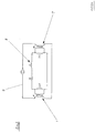
- the device in Fig. 1 has a first magnetic Current transformer 1 on. Through this converter 1 is a electrical conductor strand 2 with the conductors L1, L2, L3 and N led.
- the Tripping unit 5 acts mechanically on the conductors L1, L2, L3, N inserted rear derailleur 6, so that when a certain differential current occurs Interruption of the led over the conductor strand 2 Route.
- the device according to the invention is thus designed as a residual current protection device.
- the first current transformer 1 is a second current transformer 7 downstream.
- the electrical conductor strand 2 is with its conductors following the first converter 1 led the second converter 7.
- the converter 7 can further course of the electrical conduction path z. B. a Frequency converter must be connected downstream.
- the second converter 7 is connected to the via a coupling element 8 first converter 1 connected.
- the coupling element 8 is how 2 recognizable from a resistor R1 and the Inductors LW 1 and LW 2 of the converter 1 (W1) and 7 (W2) designed as a high-pass filter of the first order.
- the Equivalent circuit shows a simple passive design the device according to the invention with a primary differential current path 9 is applied.
- inductor L1 in Series connected so that through the coupling element 8 at the same time a simple low pass is formed.
- FIG. 3 shows the course of the continuous line 10 identified triggering threshold for the device according to Figures 1 and 2 on the frequency.
- the tripping current is smaller than 30 mA.
- the tripping current increases to over 100 mA.
- dash-dotted lines in Fig. 3 are minimal and maximum threshold values according to report IEC 479 identified.
- the course of the tripping current is advantageously in a range between yet permissible minimum and maximum values.
- a dashed Line at about 400 mA shows a top one Tripping current for fire protection reasons. To this Line 10 is approaching the limit at high frequencies of 10,000 Hz and above without reaching it.
- a coupling element 29 determines in the negative feedback circuit alone or together with the inductors of the windings N12 and N22 the amplitudes / frequency - Characteristic of the negative feedback current.
- the detection frequency range of the differential current up to very high frequencies, i.e. until the MHz range is expanded.
- the negative feedback circuit 217 switched low-resistance current measuring resistor 210 linked to the evaluation device 216.
- the current measuring resistor 210 is one of the negative feedback current proportional voltage available a second detection path of the evaluation device 216 can be fed directly or via further signal processing units.
- the negative feedback current is the upper frequency components of the Differential current with the amplitude / frequency curve contains, which is canceled in the converter 1 due to the negative feedback , they can be found in both signal paths transmitted frequency spectra after a gain adjustment in an ideal way again completely to the original total frequency spectrum of the differential current add up what a smooth frequency response of the Response current of the RCD corresponds.
- the current transformer 1 is part of a modulating oscillating circuit in accordance with the invention with only one secondary winding, whereby a simple alternating bias of the current transformer 1 with an alternating current of a high carrier frequency f T is made possible.
- the use of a separate frequency generator with subsequent filter stages can advantageously be dispensed with.
- a circuit 22 and the winding N13 modulating oscillation circuit simple and inexpensive can be designed as a rectangular generator (multivibrator).
- 5 shows a possible design of the frequency generator as a multivibrator with a comparator or Operational amplifier U1.
- the inductance is the Winding N13 on the core of the first current transformer 1 together with the ohmic resistors R1, R2 and R3 frequency-determining.
- the core of the first current transformer 1 can advantageously consist of a low-loss nanocrystalline or amorphous material with a small inductance factor.
- At least one low-pass filter 23 is arranged in the line path downstream of the square-wave generator forming the circuit 22 for demodulation.
- the low-pass filter 23 is designed, for example, as an active higher-order filter with a steep slope in the stop band and a cut-off frequency well below the carrier frequency f T. At the output of the low-pass filter 23, only the image of the differential current is thus obtained and fed to the evaluation.
- the evaluation device 216 preferably has, among other things for evaluating the signals of the lower frequency spectrum from the low pass 23 and the higher frequency, from the negative feedback current derived signals a summing amplifier 24 with subsequent two-way rectifier 25.
- the summing amplifier 24 enables that at device according to the invention detected in two ways Differential current spectra through different amplification assigned to different rated residual currents can be. For example, for realization of personal protection with a rated residual current of 30 mA from the first current transformer 1 only residual current spectral components from 0 to about 100 Hz separated while out of the current negative feedback generated signal further differential current spectral components recorded in the MHz range and to implement a Fire protection with a rated residual current of 300 mA be assigned.
- the two-way rectifier 25 at least one comparator circuit 27 as a component is arranged downstream of the evaluation device 216.
- a low-pass filter 26 be arranged with which a cutoff frequency is set is that the following comparator also on Amplitudes of 50 Hz pulse differential current signals within that addresses the limits required in the relevant standards.
- the comparator circuit 27 preferably has two in succession switched comparators, the second Comparator is assigned a low-pass filter.
- the second Comparator with the low-pass filter serves that the Device according to the invention with short transients Residual currents do not respond.
- the Low pass circuit reaches a delay which a Only respond at the maximum permitted tripping time causes. This increases the interference immunity of the invention Contraption.
- Device for rated residual currents> 30mA can thus be set response times that the device according to the invention a property as Give time-selective residual current protective device.
- the comparator circuit 27 with at least a trigger relay 213 linked at submission of a differential current causes, for example a mechanical contact device the route of the load current interrupts.
- the trip relay 213 with certain secondary windings N22, N12 of the two current transformers 1, 7 can be linked, the link via a switch contact 28 is made, which of at least applied to an undervoltage detector 214 in a switching manner is.
- the device according to the invention is thereby independent of auxiliary voltage even in an undervoltage range like a conventional residual current circuit breaker for the detection of residual currents in a restricted Frequency range can be used. Is that for them auxiliary voltage-dependent modules of the invention Required mains voltage below a defined value, so certain secondary windings N22, N12 of the two current transformers 1, 7 directly with the excitation coil of the trigger relay is connected.
- the Switch contact 28 provides the conductive connection between these components.
- an electrical Matching circuit 212 is arranged between Switch contact 28 and trigger relay 213. Is the tension below a defined value, for example below of 50V, the switch contact 28 connects the secondary winding electrically connected in series N22 of the second current transformer 7 and one second secondary winding N12 of the first current transformer 1 with this electrical matching circuit 212. This forms in connection with the inductances of both current transformers 1, 7 and the trigger relay a series and parallel resonant circuit from which in a known manner for Detection of AC and pulse differential currents can be used is. If the voltage is above a defined one Value, the switch contact 28 switches and sets one conductive connection between the winding N12 and the in Row to the coupling element 29 arranged current measuring resistor 210 ago.
- the coupling member 29 in the simplest way is designed as an ohmic resistor, which together with the inductances of the windings N12 and N22 for the Current in the negative feedback circuit a high pass first Forms order with the cut-off frequency fg. Because in this case a significantly higher voltage across resistor 210 drops as at a low-resistance current measuring resistor, the signal processing in the further stages simple and less prone to failure.
- the core of the first current transformer 1 and the core of the second current transformer 7 in arranged as a protective trough housing are. Both cores therefore contribute particularly to the Undervoltage drop to form a larger inductance in order to trigger independent of the auxiliary voltage with alternating and pulse differential currents.
- FIG. 4 shows two electrical conductors 21 acting as primary windings N11a and N11b and N21a and N22a of two magnetic current transformers 1 and 7 are executed.
- the first current transformer 1 has two separate ones Secondary windings N13 and N12.
- the first Secondary winding N13 is together with the circuit 22 an oscillating circuit designed as a rectangular generator (Fig. 2).
- the rectangle generator is with the Low pass 23 interconnected, that as part of an evaluation device 216 of the summing amplifier 24 with the following Two-way rectifier 25 follows in the line path.
- the second secondary winding N12 of the first current transformer 1 and the secondary winding N22 of the second current transformer 7 are in series with a switching element 28 arranged coupling element 29 and current measuring resistor 210 connected.
- the current measuring resistor 210 is through the delay circuit 211 also with the summing amplifier 24 linked.
- the summarized in the summing amplifier 24 Signals are sent via a two-way rectifier 25 and the subsequent low pass 26 of the comparator circuit 27 fed. This comparator circuit 27 is linked to the trigger relay 213.
- the switch contact 28 in the circuit of the secondary windings N12 and N22 are connected to undervoltage detector 214 in interaction causing its switching.
- the block diagram shows the state when presented Undervoltage. In this case, the secondary windings N12 and N22 of both current transformers 1, 7 via the electrical Matching circuit 212 directly with the trigger relay 213 connected.
Landscapes
- Engineering & Computer Science (AREA)
- Power Engineering (AREA)
- Measurement Of Current Or Voltage (AREA)
- Measuring Instrument Details And Bridges, And Automatic Balancing Devices (AREA)
- Transformers For Measuring Instruments (AREA)
- Amplifiers (AREA)
Applications Claiming Priority (4)
| Application Number | Priority Date | Filing Date | Title |
|---|---|---|---|
| DE10128311A DE10128311C2 (de) | 2001-06-12 | 2001-06-12 | Vorrichtung zum Erfassen von elektrischen Differenzströmen |
| DE10128311 | 2001-06-12 | ||
| DE10215019 | 2002-04-05 | ||
| DE2002115019 DE10215019B4 (de) | 2002-04-05 | 2002-04-05 | Vorrichtung zum Erfassen von elektrischen Differenzströmen |
Publications (3)
| Publication Number | Publication Date |
|---|---|
| EP1267467A2 true EP1267467A2 (fr) | 2002-12-18 |
| EP1267467A3 EP1267467A3 (fr) | 2006-03-08 |
| EP1267467B1 EP1267467B1 (fr) | 2012-03-21 |
Family
ID=26009502
Family Applications (1)
| Application Number | Title | Priority Date | Filing Date |
|---|---|---|---|
| EP02012819A Expired - Lifetime EP1267467B1 (fr) | 2001-06-12 | 2002-06-10 | Dispositif pour la détection des courants différentiels |
Country Status (4)
| Country | Link |
|---|---|
| EP (1) | EP1267467B1 (fr) |
| AT (1) | ATE550819T1 (fr) |
| ES (1) | ES2385806T3 (fr) |
| PL (1) | PL199597B1 (fr) |
Cited By (15)
| Publication number | Priority date | Publication date | Assignee | Title |
|---|---|---|---|---|
| WO2005050229A1 (fr) * | 2003-11-24 | 2005-06-02 | Dipl.-Ing. Walther Bender Gmbh & Co. Kg | Procede pour determiner la resistance d'isolement ohmique |
| EP1696444A2 (fr) | 2005-02-17 | 2006-08-30 | Siemens Aktiengesellschaft | Transformateur de courant sommateur |
| WO2006136520A1 (fr) * | 2005-06-22 | 2006-12-28 | Siemens Aktiengesellschaft | Analyseur de courant de fuite destine a detecter un courant de fuite et dispositif presentant une fonction de detection de courant de fuite |
| US8315023B2 (en) | 2008-12-02 | 2012-11-20 | Moeller Gebäudeautomation GmbH | Residual-current circuit breaker |
| DE102011107721A1 (de) | 2011-07-14 | 2013-01-17 | Ean Elektroschaltanlagen Gmbh | Verfahren und Vorrichtung zur Messung elektrischer Ströme mit Hilfe eines Stromwandlers |
| CN102890196A (zh) * | 2011-07-20 | 2013-01-23 | 本德尔有限两合公司 | 用于将测量信号电压外施加到供电网上的方法和装置 |
| DE102013204638A1 (de) * | 2012-12-12 | 2014-06-12 | Panasonic Industrial Devices Europe Gmbh | Vorrichtung zur Erfassung von Fehlerströmen |
| EP2765665A2 (fr) | 2013-02-09 | 2014-08-13 | Doepke Schaltgeräte GmbH | Dispositif de détection de courants électriques différentiels, notamment de courants mélangés constitués de courant continu lisse et de courants alternatifs |
| DE102013114780A1 (de) * | 2013-12-23 | 2015-06-25 | Refusol Gmbh | Strommessvorrichtung |
| EP3232526A1 (fr) | 2016-04-12 | 2017-10-18 | Schneider Electric Industries SAS | Dispositif de détection d'un courant de défaut |
| EP3757580A1 (fr) | 2019-06-25 | 2020-12-30 | Doepke Schaltgeräte GmbH | Dispositif de détection de courants différentiels dans des installation électriques alimentées en courant continu |
| DE102011011984B4 (de) * | 2011-02-22 | 2021-06-10 | Doepke Schaltgeräte GmbH | Fehlerstrom-Schutzeinrichtung mit frequenzabhängiger Schaltung zur Spannungsvervielfachung |
| DE102020102689A1 (de) | 2020-02-04 | 2021-08-05 | Doepke Schaltgeräte GmbH | Schutzschalteinrichtung |
| EP3121609B1 (fr) | 2014-03-21 | 2021-09-01 | Seari Electric Technology Co., Ltd. | Dispositif de détection de courant continu-courant résiduel |
| DE102021133662A1 (de) | 2021-12-14 | 2023-06-15 | Doepke Schaltgeräte GmbH | Verfahren zur Erkennung von Fehlerzuständen eines Schutzleiters |
Citations (2)
| Publication number | Priority date | Publication date | Assignee | Title |
|---|---|---|---|---|
| DE3531023A1 (de) * | 1985-08-30 | 1987-03-05 | Bbc Brown Boveri & Cie | Schaltungsanordnung zur erfassung eines fehler- bzw. differenzstromes |
| DE3543985A1 (de) * | 1985-12-12 | 1987-06-19 | Siemens Ag | Anordnung zum erfassen von fehlerstroemen |
-
2002
- 2002-06-10 AT AT02012819T patent/ATE550819T1/de active
- 2002-06-10 EP EP02012819A patent/EP1267467B1/fr not_active Expired - Lifetime
- 2002-06-10 ES ES02012819T patent/ES2385806T3/es not_active Expired - Lifetime
- 2002-06-12 PL PL354431A patent/PL199597B1/pl unknown
Patent Citations (2)
| Publication number | Priority date | Publication date | Assignee | Title |
|---|---|---|---|---|
| DE3531023A1 (de) * | 1985-08-30 | 1987-03-05 | Bbc Brown Boveri & Cie | Schaltungsanordnung zur erfassung eines fehler- bzw. differenzstromes |
| DE3543985A1 (de) * | 1985-12-12 | 1987-06-19 | Siemens Ag | Anordnung zum erfassen von fehlerstroemen |
Cited By (24)
| Publication number | Priority date | Publication date | Assignee | Title |
|---|---|---|---|---|
| WO2005050229A1 (fr) * | 2003-11-24 | 2005-06-02 | Dipl.-Ing. Walther Bender Gmbh & Co. Kg | Procede pour determiner la resistance d'isolement ohmique |
| DE102005007334B4 (de) * | 2005-02-17 | 2007-02-08 | Siemens Ag | Summenstromwandler zur allstromsensitiven Erfassung eines elektrischen Differenzstromes |
| EP1696444A2 (fr) | 2005-02-17 | 2006-08-30 | Siemens Aktiengesellschaft | Transformateur de courant sommateur |
| DE102005007334A1 (de) * | 2005-02-17 | 2006-09-07 | Siemens Ag | Summenstromwandler zur allstromsensitiven Erfassung eines elektrischen Differenzstromes |
| WO2006136520A1 (fr) * | 2005-06-22 | 2006-12-28 | Siemens Aktiengesellschaft | Analyseur de courant de fuite destine a detecter un courant de fuite et dispositif presentant une fonction de detection de courant de fuite |
| US8315023B2 (en) | 2008-12-02 | 2012-11-20 | Moeller Gebäudeautomation GmbH | Residual-current circuit breaker |
| DE102011011984B4 (de) * | 2011-02-22 | 2021-06-10 | Doepke Schaltgeräte GmbH | Fehlerstrom-Schutzeinrichtung mit frequenzabhängiger Schaltung zur Spannungsvervielfachung |
| DE102011107721A1 (de) | 2011-07-14 | 2013-01-17 | Ean Elektroschaltanlagen Gmbh | Verfahren und Vorrichtung zur Messung elektrischer Ströme mit Hilfe eines Stromwandlers |
| WO2013007240A1 (fr) | 2011-07-14 | 2013-01-17 | Ean Elektroschaltanlagen Gmbh | Procédé et dispositif de mesure de courants électriques l'aide d'un transformateur de courant |
| CN102890196A (zh) * | 2011-07-20 | 2013-01-23 | 本德尔有限两合公司 | 用于将测量信号电压外施加到供电网上的方法和装置 |
| US9157944B2 (en) | 2011-07-20 | 2015-10-13 | Bender Gmbh & Co. Kg | Method and a device for impressing a measuring-signal voltage on a power supply network |
| CN102890196B (zh) * | 2011-07-20 | 2015-08-05 | 本德尔有限两合公司 | 用于将测量信号电压外施加到供电网上的方法和装置 |
| DE102013204638A1 (de) * | 2012-12-12 | 2014-06-12 | Panasonic Industrial Devices Europe Gmbh | Vorrichtung zur Erfassung von Fehlerströmen |
| DE102013204638B4 (de) | 2012-12-12 | 2019-04-04 | Panasonic Industrial Devices Europe Gmbh | Vorrichtung zur Erfassung von Fehlerströmen |
| DE102013002376A1 (de) | 2013-02-09 | 2014-08-14 | Doepke Schaltgeräte GmbH | Vorrichtung zur Erfassung von elektrischen Differenzströmen, insbesondere von Mischströmen aus glattem Gleichstrom und Wechselströmen |
| EP2765665A3 (fr) * | 2013-02-09 | 2015-09-09 | Doepke Schaltgeräte GmbH | Dispositif de détection de courants électriques différentiels, notamment de courants mélangés constitués de courant continu lisse et de courants alternatifs |
| EP2765665A2 (fr) | 2013-02-09 | 2014-08-13 | Doepke Schaltgeräte GmbH | Dispositif de détection de courants électriques différentiels, notamment de courants mélangés constitués de courant continu lisse et de courants alternatifs |
| DE102013114780A1 (de) * | 2013-12-23 | 2015-06-25 | Refusol Gmbh | Strommessvorrichtung |
| EP3121609B1 (fr) | 2014-03-21 | 2021-09-01 | Seari Electric Technology Co., Ltd. | Dispositif de détection de courant continu-courant résiduel |
| EP3232526A1 (fr) | 2016-04-12 | 2017-10-18 | Schneider Electric Industries SAS | Dispositif de détection d'un courant de défaut |
| EP3757580A1 (fr) | 2019-06-25 | 2020-12-30 | Doepke Schaltgeräte GmbH | Dispositif de détection de courants différentiels dans des installation électriques alimentées en courant continu |
| DE102019117103A1 (de) * | 2019-06-25 | 2020-12-31 | Doepke Schaltgeräte GmbH | Vorrichtung zur Erfassung von Differenzströmen in gleichstromgespeisten elektrischen Anlagen |
| DE102020102689A1 (de) | 2020-02-04 | 2021-08-05 | Doepke Schaltgeräte GmbH | Schutzschalteinrichtung |
| DE102021133662A1 (de) | 2021-12-14 | 2023-06-15 | Doepke Schaltgeräte GmbH | Verfahren zur Erkennung von Fehlerzuständen eines Schutzleiters |
Also Published As
| Publication number | Publication date |
|---|---|
| PL199597B1 (pl) | 2008-10-31 |
| ATE550819T1 (de) | 2012-04-15 |
| EP1267467A3 (fr) | 2006-03-08 |
| EP1267467B1 (fr) | 2012-03-21 |
| ES2385806T3 (es) | 2012-08-01 |
| PL354431A1 (en) | 2002-12-16 |
Similar Documents
| Publication | Publication Date | Title |
|---|---|---|
| EP1267467B1 (fr) | Dispositif pour la détection des courants différentiels | |
| DE112005001167B4 (de) | Differenzstromdetektion | |
| DE69024975T2 (de) | Spektrumerfassung von lichtbögen und radiofrequenzen | |
| EP0267500B1 (fr) | Méthode et dispositif pour localiser un défaut de terre dans un réseau électrique triphasé | |
| EP2765665B1 (fr) | Dispositif de détection de courants électriques différentiels, notamment de courants mélangés constitués de courant continu lisse et de courants alternatifs | |
| DE19826410A1 (de) | Verfahren und Einrichtung zur Isolations- und Fehlerstromüberwachung in einem elektrischen Wechselstromnetz | |
| DE102019204272B4 (de) | Fehlerstromschutzeinheit und Verfahren | |
| DE102014214160A1 (de) | Vorrichtung zum Erfassen eines Fehlerstromes in einem Ladekabel und Ladekabel welches dieselbe aufweist | |
| EP0643309A1 (fr) | Procédé pour détecter des défauts à la terre des conducteurs d'une machine électrique | |
| EP1206823B1 (fr) | Dispositif de protection, en particulier dispositif de protection actionne par courant de defaut | |
| DE2851381C2 (de) | Fehlerstrom-Schutzschaltung für Gleich- und/oder Wechselstrom | |
| EP3757580B1 (fr) | Dispositif de détection de courants différentiels dans des installation électriques alimentées en courant continu | |
| EP0273255B1 (fr) | Interrupteur de protection à courant différentiel | |
| EP3226013A1 (fr) | Capteur de courant différentiel | |
| DE69018344T2 (de) | Differentialschutzrelais. | |
| DE2502322C2 (de) | Erdschluß-Schutzeinrichtung | |
| DE3888750T2 (de) | Vorrichtung und Verfahren zum Diskriminieren von Signalen. | |
| EP1478070B1 (fr) | Dispositif de protection sensible à tout courant de défaut | |
| DE10128311C2 (de) | Vorrichtung zum Erfassen von elektrischen Differenzströmen | |
| DE10215019A1 (de) | Vorrichtung zum Erfassen von elektrischen Differenzströmen | |
| DE2555255B2 (de) | Einrichtung zur Erfassung von Fehlerströmen | |
| DE102008037830A1 (de) | Fehlerstromerfassungsgerät | |
| DE4128961C1 (en) | Detecting short circuit to earth in pulse inverter - using square wave HF voltage source in evaluation circuit to operate protection circuit when toroidal transformer saturates | |
| WO2014187951A1 (fr) | Commutateur de protection contre les courants de fuite (élément rc) | |
| DE2613972A1 (de) | Fehlerstromschutzschalter |
Legal Events
| Date | Code | Title | Description |
|---|---|---|---|
| PUAI | Public reference made under article 153(3) epc to a published international application that has entered the european phase |
Free format text: ORIGINAL CODE: 0009012 |
|
| AK | Designated contracting states |
Kind code of ref document: A2 Designated state(s): AT BE CH CY DE DK ES FI FR GB GR IE IT LI LU MC NL PT SE TR |
|
| AX | Request for extension of the european patent |
Free format text: AL;LT;LV;MK;RO;SI |
|
| PUAL | Search report despatched |
Free format text: ORIGINAL CODE: 0009013 |
|
| AK | Designated contracting states |
Kind code of ref document: A3 Designated state(s): AT BE CH CY DE DK ES FI FR GB GR IE IT LI LU MC NL PT SE TR |
|
| AX | Request for extension of the european patent |
Extension state: AL LT LV MK RO SI |
|
| 17P | Request for examination filed |
Effective date: 20060608 |
|
| AKX | Designation fees paid |
Designated state(s): AT BE CH CY DE DK ES FI FR GB GR IE IT LI LU MC NL PT SE TR |
|
| AXX | Extension fees paid |
Extension state: LV Payment date: 20060608 Extension state: LT Payment date: 20060608 Extension state: MK Payment date: 20060608 Extension state: AL Payment date: 20060608 Extension state: RO Payment date: 20060608 Extension state: SI Payment date: 20060608 |
|
| 17Q | First examination report despatched |
Effective date: 20090603 |
|
| GRAP | Despatch of communication of intention to grant a patent |
Free format text: ORIGINAL CODE: EPIDOSNIGR1 |
|
| GRAS | Grant fee paid |
Free format text: ORIGINAL CODE: EPIDOSNIGR3 |
|
| RAP1 | Party data changed (applicant data changed or rights of an application transferred) |
Owner name: DOEPKE SCHALTGERAETE GMBH |
|
| GRAA | (expected) grant |
Free format text: ORIGINAL CODE: 0009210 |
|
| AK | Designated contracting states |
Kind code of ref document: B1 Designated state(s): AT BE CH CY DE DK ES FI FR GB GR IE IT LI LU MC NL PT SE TR |
|
| AX | Request for extension of the european patent |
Extension state: AL LT LV MK RO SI |
|
| REG | Reference to a national code |
Ref country code: GB Ref legal event code: FG4D Free format text: NOT ENGLISH |
|
| REG | Reference to a national code |
Ref country code: CH Ref legal event code: EP |
|
| REG | Reference to a national code |
Ref country code: IE Ref legal event code: FG4D Free format text: LANGUAGE OF EP DOCUMENT: GERMAN |
|
| REG | Reference to a national code |
Ref country code: AT Ref legal event code: REF Ref document number: 550819 Country of ref document: AT Kind code of ref document: T Effective date: 20120415 |
|
| REG | Reference to a national code |
Ref country code: DE Ref legal event code: R096 Ref document number: 50215418 Country of ref document: DE Effective date: 20120516 |
|
| REG | Reference to a national code |
Ref country code: NL Ref legal event code: T3 |
|
| REG | Reference to a national code |
Ref country code: ES Ref legal event code: FG2A Ref document number: 2385806 Country of ref document: ES Kind code of ref document: T3 Effective date: 20120801 |
|
| LTLA | Lt: lapse of european patent or patent extension | ||
| PG25 | Lapsed in a contracting state [announced via postgrant information from national office to epo] |
Ref country code: FI Free format text: LAPSE BECAUSE OF FAILURE TO SUBMIT A TRANSLATION OF THE DESCRIPTION OR TO PAY THE FEE WITHIN THE PRESCRIBED TIME-LIMIT Effective date: 20120321 Ref country code: GR Free format text: LAPSE BECAUSE OF FAILURE TO SUBMIT A TRANSLATION OF THE DESCRIPTION OR TO PAY THE FEE WITHIN THE PRESCRIBED TIME-LIMIT Effective date: 20120622 |
|
| PG25 | Lapsed in a contracting state [announced via postgrant information from national office to epo] |
Ref country code: CY Free format text: LAPSE BECAUSE OF FAILURE TO SUBMIT A TRANSLATION OF THE DESCRIPTION OR TO PAY THE FEE WITHIN THE PRESCRIBED TIME-LIMIT Effective date: 20120321 |
|
| PG25 | Lapsed in a contracting state [announced via postgrant information from national office to epo] |
Ref country code: SE Free format text: LAPSE BECAUSE OF FAILURE TO SUBMIT A TRANSLATION OF THE DESCRIPTION OR TO PAY THE FEE WITHIN THE PRESCRIBED TIME-LIMIT Effective date: 20120321 |
|
| PG25 | Lapsed in a contracting state [announced via postgrant information from national office to epo] |
Ref country code: PT Free format text: LAPSE BECAUSE OF FAILURE TO SUBMIT A TRANSLATION OF THE DESCRIPTION OR TO PAY THE FEE WITHIN THE PRESCRIBED TIME-LIMIT Effective date: 20120723 |
|
| BERE | Be: lapsed |
Owner name: DOEPKE SCHALTGERATE G.M.B.H. Effective date: 20120630 |
|
| PLBE | No opposition filed within time limit |
Free format text: ORIGINAL CODE: 0009261 |
|
| STAA | Information on the status of an ep patent application or granted ep patent |
Free format text: STATUS: NO OPPOSITION FILED WITHIN TIME LIMIT |
|
| PG25 | Lapsed in a contracting state [announced via postgrant information from national office to epo] |
Ref country code: MC Free format text: LAPSE BECAUSE OF NON-PAYMENT OF DUE FEES Effective date: 20120630 Ref country code: DK Free format text: LAPSE BECAUSE OF FAILURE TO SUBMIT A TRANSLATION OF THE DESCRIPTION OR TO PAY THE FEE WITHIN THE PRESCRIBED TIME-LIMIT Effective date: 20120321 |
|
| REG | Reference to a national code |
Ref country code: CH Ref legal event code: PL |
|
| REG | Reference to a national code |
Ref country code: CH Ref legal event code: PL |
|
| 26N | No opposition filed |
Effective date: 20130102 |
|
| REG | Reference to a national code |
Ref country code: IE Ref legal event code: MM4A |
|
| REG | Reference to a national code |
Ref country code: DE Ref legal event code: R097 Ref document number: 50215418 Country of ref document: DE Effective date: 20130102 |
|
| PG25 | Lapsed in a contracting state [announced via postgrant information from national office to epo] |
Ref country code: BE Free format text: LAPSE BECAUSE OF NON-PAYMENT OF DUE FEES Effective date: 20120630 Ref country code: CH Free format text: LAPSE BECAUSE OF NON-PAYMENT OF DUE FEES Effective date: 20120630 Ref country code: LI Free format text: LAPSE BECAUSE OF NON-PAYMENT OF DUE FEES Effective date: 20120630 Ref country code: IE Free format text: LAPSE BECAUSE OF NON-PAYMENT OF DUE FEES Effective date: 20120610 |
|
| PG25 | Lapsed in a contracting state [announced via postgrant information from national office to epo] |
Ref country code: TR Free format text: LAPSE BECAUSE OF FAILURE TO SUBMIT A TRANSLATION OF THE DESCRIPTION OR TO PAY THE FEE WITHIN THE PRESCRIBED TIME-LIMIT Effective date: 20120321 |
|
| PG25 | Lapsed in a contracting state [announced via postgrant information from national office to epo] |
Ref country code: LU Free format text: LAPSE BECAUSE OF NON-PAYMENT OF DUE FEES Effective date: 20120610 |
|
| REG | Reference to a national code |
Ref country code: FR Ref legal event code: PLFP Year of fee payment: 15 |
|
| REG | Reference to a national code |
Ref country code: FR Ref legal event code: PLFP Year of fee payment: 16 |
|
| REG | Reference to a national code |
Ref country code: FR Ref legal event code: PLFP Year of fee payment: 17 |
|
| PGFP | Annual fee paid to national office [announced via postgrant information from national office to epo] |
Ref country code: DE Payment date: 20210408 Year of fee payment: 20 Ref country code: FR Payment date: 20210621 Year of fee payment: 20 Ref country code: IT Payment date: 20210630 Year of fee payment: 20 Ref country code: NL Payment date: 20210621 Year of fee payment: 20 |
|
| PGFP | Annual fee paid to national office [announced via postgrant information from national office to epo] |
Ref country code: GB Payment date: 20210623 Year of fee payment: 20 Ref country code: AT Payment date: 20210618 Year of fee payment: 20 |
|
| PGFP | Annual fee paid to national office [announced via postgrant information from national office to epo] |
Ref country code: ES Payment date: 20210722 Year of fee payment: 20 |
|
| REG | Reference to a national code |
Ref country code: DE Ref legal event code: R071 Ref document number: 50215418 Country of ref document: DE |
|
| REG | Reference to a national code |
Ref country code: NL Ref legal event code: MK Effective date: 20220609 |
|
| REG | Reference to a national code |
Ref country code: GB Ref legal event code: PE20 Expiry date: 20220609 |
|
| PG25 | Lapsed in a contracting state [announced via postgrant information from national office to epo] |
Ref country code: GB Free format text: LAPSE BECAUSE OF EXPIRATION OF PROTECTION Effective date: 20220609 |
|
| REG | Reference to a national code |
Ref country code: ES Ref legal event code: FD2A Effective date: 20220802 |
|
| REG | Reference to a national code |
Ref country code: AT Ref legal event code: MK07 Ref document number: 550819 Country of ref document: AT Kind code of ref document: T Effective date: 20220610 |
|
| PG25 | Lapsed in a contracting state [announced via postgrant information from national office to epo] |
Ref country code: ES Free format text: LAPSE BECAUSE OF EXPIRATION OF PROTECTION Effective date: 20220611 |