EP1267449A2 - Ring tongue lug retainer molded case circuit breaker - Google Patents
Ring tongue lug retainer molded case circuit breaker Download PDFInfo
- Publication number
- EP1267449A2 EP1267449A2 EP02077173A EP02077173A EP1267449A2 EP 1267449 A2 EP1267449 A2 EP 1267449A2 EP 02077173 A EP02077173 A EP 02077173A EP 02077173 A EP02077173 A EP 02077173A EP 1267449 A2 EP1267449 A2 EP 1267449A2
- Authority
- EP
- European Patent Office
- Prior art keywords
- circuit breaker
- ring tongue
- lug
- load
- housing
- Prior art date
- Legal status (The legal status is an assumption and is not a legal conclusion. Google has not performed a legal analysis and makes no representation as to the accuracy of the status listed.)
- Granted
Links
Images

Classifications
-
- H—ELECTRICITY
- H01—ELECTRIC ELEMENTS
- H01R—ELECTRICALLY-CONDUCTIVE CONNECTIONS; STRUCTURAL ASSOCIATIONS OF A PLURALITY OF MUTUALLY-INSULATED ELECTRICAL CONNECTING ELEMENTS; COUPLING DEVICES; CURRENT COLLECTORS
- H01R4/00—Electrically-conductive connections between two or more conductive members in direct contact, i.e. touching one another; Means for effecting or maintaining such contact; Electrically-conductive connections having two or more spaced connecting locations for conductors and using contact members penetrating insulation
- H01R4/28—Clamped connections, spring connections
- H01R4/30—Clamped connections, spring connections utilising a screw or nut clamping member
- H01R4/36—Conductive members located under tip of screw
-
- H—ELECTRICITY
- H01—ELECTRIC ELEMENTS
- H01H—ELECTRIC SWITCHES; RELAYS; SELECTORS; EMERGENCY PROTECTIVE DEVICES
- H01H1/00—Contacts
- H01H1/58—Electric connections to or between contacts; Terminals
- H01H1/5855—Electric connections to or between contacts; Terminals characterised by the use of a wire clamping screw or nut
- H01H2001/5861—Box connector with a collar or lug for clamping internal rail and external conductor together by a tightening screw
-
- H—ELECTRICITY
- H01—ELECTRIC ELEMENTS
- H01H—ELECTRIC SWITCHES; RELAYS; SELECTORS; EMERGENCY PROTECTIVE DEVICES
- H01H71/00—Details of the protective switches or relays covered by groups H01H73/00 - H01H83/00
- H01H71/08—Terminals; Connections
Definitions
- the present invention relates generally to the field of circuit breakers, and more particularly to a ring tongue lug retainer for a molded case circuit breaker.
- a circuit breaker In general the function of a circuit breaker is to electrically engage and disengage a selected circuit from an electrical power supply. This function occurs by engaging and disengaging a pair of operating contacts for each phase of the circuit breaker.
- the circuit breaker provides protection against persistent overcurrent conditions and against the very high currents produced by short circuits.
- one of each pair of the operating contacts are supported by a pivoting contact arm while the other operating contact is substantially stationary.
- the contact arm is pivoted by an operating mechanism such that the movable contact supported by the contact arm can be engaged and disengaged from the stationary contact.
- a typical industrial circuit breaker will have a continuous current rating ranging from as low as 15 amps to as high as several thousand amps.
- the tripping mechanism for the breaker usually consists of a thermal overload release and a magnetic short circuit release.
- the thermal overload release operates by means of a bimetallic element, in which current flowing through the conducting path of a circuit breaker generates heat in the bi-metal element, which causes the bi-metal to deflect and trip the breaker.
- the heat generated in the bi-metal is a function of the amount of current flowing through the bi-metal as well as the period of time that that current is flowing.
- the bi-metal cross- section and related elements are specifically selected for such current range resulting in a number of different current ranges for each circuit breaker. Electronic trip units are also used in some applications.
- an electromagnetic trip element is generally used.
- the higher amount of current flowing through the circuit breaker activates a magnetic release which trips the breaker in a much faster time than occurs with the bi-metal heating.
- It is desirable to tune the magnetic trip elements so that the magnetic trip unit trips at lower short circuit currents at a lower continuous current rating and trips at a higher short circuit current at a higher continuous current rating. This matches the current tripping performance of the breaker with the typical equipment present downstream of the breaker on the load side of the circuit breaker.
- electronic trip units can also be used.
- circuit breakers are continually increasing due to market driven requirements for space saving electrical equipment. As the ampere rating for a given circuit breaker frame size increases, space for wiring lugs within that circuit breaker becomes a premium. Lug size for attaching the various wires and cables is primarily driven by the wiring cable dimensions as defined in the National Electric Code or other country specific wiring standards or practices. Although this problem exists for all circuit breakers, it is especially acute for circuit breakers in the 100 amp to 125 amp range.
- a lug mounted in the circuit breaker Existing techniques for connection of the various wires and cables relative to the circuit breaker is done with a lug mounted in the circuit breaker.
- a wire or cable is inserted into the lug and a screw is turned and engages the wire typically with a crushing or squashing of the wires as the screw is turned down in the lug.
- the screw may have a plate fixed at its bottom with prongs that engage the cable or wire.
- the lug is typically mounted in the circuit breaker either by additional hardware such as screws or rivets or by a series of tabs and notches configured in either the housing of the circuit breaker or the lug or both.
- a wire or cable has a ring tongue connector or the like mounted by solder or crimping as a terminator for the wire end.
- the ring tongue connector is then bolted or screwed to the line and load bus conductors of the circuit breaker.
- the ring tongue is simply squeezed by the lug screw as the lug screw is turned into the wire lug, usually with less than 100% mechanical or electrical contact being made between the ring tongue connector and the electrical bus conductor.
- the existing wiring connections require either additional hardware, special manufacturing techniques for the wire lug and circuit breaker housing, or the electrical connection does not utilize the entire portion of the ring tongue terminator which is engaged by the wire lug of the circuit breaker.
- the present invention provides a ring tongue lug retainer in a circuit breaker with the circuit breaker having a line bus conductor and a load bus conductor, wherein electrical conductors are connected to the line and load bus conductors.
- the ring tongue lug retainer comprises a lug body having a throughbore defining at least two interior walls and a threaded screw hole aligned perpendicular to and in communication with the throughbore. A thread portion in each interior wall of the lug body may be provided to engage the binding screw configured to threadingly engage the screw hole and the lug body.
- the binding screw has a ring tongue protrusion configured to engage a ring tongue terminal of the electrical conductors.
- the ring tongue protrusion can be one selected from a group comprising a cylinder with a round end, a trunkated cone, a cylinder with a pointed end and a cylinder with a flat end and spherical knob.
- Another embodiment of the ring tongue lug retainer includes a slot extending into the lug body and in communication with the throughbore. The slot can be configured to engage one of the line bus conductor and load bus conductor and the slot may extend through the lug body.
- the present invention further provides a molded case circuit breaker comprising a molded housing, a line bus conductor and a load bus conductor inserted in the housing with the first contact coupled to the line bus conductor and a second contact coupled to the load bus conductor.
- An operating mechanism having a pivoting member movable between an "ON" position, and “OFF” position and a "TRIPPED” position, with the pivoting member coupled to the second contact.
- a trip unit coupled to the second contact and the load bus conductor is selectively in operative contact with the operating mechanism.
- An electric arc extinguishing apparatus is mounted in the housing and is positioned in confronting relation with the first and second contacts, a ring tongue lug retainer is mounted in the circuit breaker housing at one of the load and line terminals.
- the ring tongue lug retainer comprises a lug body having a throughbore defining at least two interior walls and a threaded screw hole aligned perpendicular to and in communication with the throughbore.
- a thread portion in each interior wall of the lug body may be provided and a binding screw configured to threadingly engage the screw hole and the lug body.
- the binding screw has a ring tongue protrusion configured to engage a terminal, such as a ring tongue, on the electrical conductors.
- the present invention also provides a circuit breaker comprising a molded housing including a base, with a means for connecting a load to the circuit breaker mounted in the housing and a means for connecting an electrical line to the circuit breaker mounted in the housing.
- a means for coupling electrically to the means for connecting an electrical line is also provided.
- a movable means for contacting the means for connecting an electrical line to a means for operating is mounted in the housing coupled with the means for operating having a pivoting member movable between an "ON" position, an "OFF” position and a "TRIPPED" position. The pivoting member is coupled to the movable means for contacting and with the means for operating.
- a means for tripping is coupled to the movable means for contacting and the means for connecting a load with the means for operating wherein the means for tripping includes a means for releasing under short circuit condition and a means for releasing under an overload condition.
- a means for extinguishing an electrical arc is mounted in the housing with a movable means for contacting extended into the means for extinguishing.
- a means for retaining having a throughbore and coupled to one of the means for connecting a load and the means for connecting an electrical line is also provided.
- the means for retaining includes the slot in communication with the throughbore.
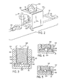
- Figure 1 is a side cut-away view of a molded case circuit breaker providing an exemplary embodiment of a lug retainer mounted in the housing at the line terminal and load terminal and with the lug retainer binding screw having a protrusion of a cylinder with a spherical knob type.
- Figure 2 is a perspective illustration of an exemplary embodiment of a ring tongue lug retainer and an electrical conductor and a bus conductor and illustrating a ring tongue protrusion of a cylinder with a flat end type.
- Figure 3 is a sectional view of an exemplary embodiment of a ring tongue lug retainer along the lines 3-3, as shown in Figure 2 and illustrating a ring tongue protrusion of a truncated cone type.
- Figure 4 is a partial sectional view of an exemplary embodiment of a ring tongue lug retainer along the lines 3-3, as shown in Figure 2 and illustrating a ring tongue protrusion of a cylinder with a round end type.
- Figure 5 is a partial sectional view of an exemplary embodiment of a ring tongue lug retainer along the lines 3-3, as shown in Figure 2 and illustrating a ring tongue protrusion of a cylinder with a pointed end type.
- Figure 1 generally illustrates single phase molded case circuit breaker 10 that includes an operating mechanism 20 having a handle 21.
- the operating mechanism 20 is mounted within a housing 18.
- the handle 21 is movable between an "ON" position, an "OFF” position and a "TRIPPED" position.
- the exemplary circuit breaker 10 is a single pole breaker however, it is contemplated that the several exemplary embodiments may be practiced in a three-phase or in other multi-phase circuit breakers. In such multi-phase breaker, each pole would have its own ring tongue lug retainer 110 aligned in the one of the line terminal 12 and load terminal 14 as dictated by the specific circuit breaker design. It is also contemplated to use an embodiment of the ring tongue lug retainer 110 in a circuit breaker having an auxiliary contact apparatus 40 as shown in Figure 1.
- the molded case circuit breaker 10 has a line terminal 12 and a load terminal 14 to which electrical wires or cables 105 are attached when the circuit breaker 10 is installed in a selected circuit.
- the housing 18 encloses the components of the circuit breaker including an operating mechanism 20 to which a main movable contact arm 30 and a trip assembly 28 are coupled.
- An auxiliary contact apparatus 40 can be mounted within a suitable void in the housing 18 of the circuit breaker 10 and coupled in series with the main movable contact arm 30. It is contemplated that an existing molded case circuit breaker will be minimally modified to accommodate the auxiliary contact apparatus 40. However, it is also contemplated that a new molded case circuit breaker design case initially incorporate the auxiliary contact apparatus 40.
- a bi-metal/magnetic trip assembly 66 is mounted in the housing 18 of the circuit breaker 10 and couples the load bus 23 to the main movable contact arm 30 via a main braid 26 through the bi-metal.
- the bi-metal assembly includes the bi-metal element 70 fixed at one end to the load bus 23 at a joint 73 formed by the load bus 23 and the bi-metal 70.
- the joint 73 is created by suitable weld or braze.
- a magnetic armature 68 and a magnetic yoke 72 form a part of the bi-metal assembly 66.
- the response characteristics of the bi-metal/magnetic trip assembly 66 is controlled by a calibrating screw 74 mounted in the load bus 23 and by the physical attributes of the trip assembly.
- the main movable contact arm 30 and main stationary contact 32 are closed.
- the current flows through the line terminal 12 into the line bus 22 and through the main stationary contact 32 into the main movable contact arm 30 of the primary contact apparatus 29.
- the current then flows through the main braid 26 into the bi-metal/magnetic trip assembly 66 and then through the load bus 23 through the load terminal 14 and onto the load (not shown).
- the current would flow from the load bus 23, through the auxiliary braid 52 into the auxiliary movable contact arm 44 and into the auxiliary movable contact arm contact pad 45 to the auxiliary stationary contact pad 43, and into the load terminal 14.
- the circuit breaker 10 Under a short circuit condition, the circuit breaker 10 will experience high current flowing through the circuit described above. Such high current will cause the magnetic yoke 72 and the magnetic armature 68 in the bi-metal/magnetic trip assembly 66 to activate the trip assembly 28 of the circuit breaker 10.
- the main movable contact on arm 30 and the main stationary contact 32 are blown apart by the magnetic force generated under the short circuit condition.
- the operating mechanism 20, trip assembly 28 and the bi-metal assembly 66 of the circuit breaker 10 also operates to hold the main movable contact arm 30 in its TRIPPED and OPENED position. With the circuit opened, the main movable contact arm 30 remains in an open position until the handle 21 of the circuit breaker 10 is reset and placed in the ON position. This can be done manually by an operator or can be done by a motor coupled to the circuit breaker or by a stored energy device coupled to the circuit breaker.
- An arc chute structure 24 typically includes two arch chute side panels having a plurality of slots support a plurality of arc plates (See Fig. 1).
- the arc plates as best seen in Fig. 1, are generally U-shaped and are stacked between the two side plates.
- the arc plates can be provided with tabs which engage the slots to form the arc chute structure.
- an arc channel is formed between the two legs of each arc plate.
- an electrical arc is drawn between the contact pads of the contact arm 30 and the stationary contact 32.
- Such electric arc extends into the arc chute structure 24 which lengthens and cools the arc as the arc voltage increases until the current ceases to flow in the circuit.
- An arc runner can also be provided on the movable contact arm to facilitate the extension, into the arc channel, of the arc generated during a short circuit condition.
- the arc runner can be integrally formed with the movable contact arm during the manufacture of the contact apparatus.
- the circuit breaker In order to increase the current rating of the circuit breaker 10, the circuit breaker must accommodate the large cables and wires used to connect the circuit breaker to the circuit being protected.
- the National Electrical Code and other countries' specific wiring standards or practices specify the size and diameter of the cables and wires to be used at specific current levels.
- the present ring tongue lug retainer 110 type of lug 15 for attaching the cable 105 to the load bus conductor 23 and line bus conductor 22 is utilized for such purposes (See Figs. 2-5).
- a circuit breaker 10 having a housing 18 with a terminal for a load connection 14 and a terminal for a line connection 12 including a ring tongue lug retainer 110 for connecting electrical conductor 105 to the line and load bus conductor 22, 23.
- the ring tongue lug retainer 110 comprises a lug body 112 having a throughbore 114 defining at least two interior walls 116 and a threaded screw hole 118 aligned perpendicular to and in communication with the throughbore 114.
- a thread portion 120 may be provided in each interior wall 116 of the lug body 112 to receive the binding screw 122.
- the binding screw 122 is configured to threadingly engage the screw hole 118 in the lug body 112 and may also engage, if provided, the thread portion 120.
- the binding screw 122 has a ring tongue protrusion 124 configured to engage the electrical conductors 105.
- the electrical conductor 105 may or may not have an end terminal attached to the conductor. In some instances the bare cable may be inserted into the lug 15 or, as illustrated in Fig. 2, an end terminal such as a ring tongue may be used.
- the ring tongue protrusion 124 can be machined, molded or formed at one end of the binding screw.
- the protrusion 124 can be one selected from a group comprising a cylinder with a round end, a truncated cone, a cylinder with a pointed end, and a cylinder with a flat end and a spherical knob. Exemplary embodiments of such ring tongue protrusions 124 are shown in Figures 1 - 5. It should be understood that other configurations for the protrusion can be utilized and configured to engage types of wire termination devices other than the ring tongue lug illustrated in Figure 2. It should also be understood that the illustrated protrusion can engage other types of wire termination devices.
- the ring tongue lug retainer 110 can include a slot 126 extending into the lug body 112 that is in communication with the throughbore 114.
- the slot 126 is configured to engage one of the line bus conductor 22 and load bus conductor 23.
- the slot 126 can also extend through the lug body 112 as illustrated in Figures 1 and 2.
- the slot is configured to engage the bus conductor 22, 23 which in addition to providing mechanical and electrical contact between the ring tongue lug of the electrical conductors 105 also provides a mechanical retention of the ring tongue lug retainer 110 within the housing 18 of the circuit breaker 10.
- Such configuration allows the ring tongue lug retainer 110 to be maintained in the circuit breaker 10 without additional hardware such as screws, rivets or notches and protrusions in the housing 18 of the circuit breaker 10.
- the ring tongue protrusion 124 of the binding screw 122 provides for 100% annular contact of the ring tongue lug and the bus conductors 22, 23 as shown in Figures 3 - 5.
- the protrusion 124 engages the hole typically found in the ring tongue lug type wire terminal. (See Figs. 2-5)
- the ring tongue lug retainer 110 can be machined, molded or cast, from a metal or from an engineered plastic of suitable strength, thermal, and electrical characteristics for the type of circuit breaker rating intended by the manufacturer.
- a circuit breaker with a line terminal and a load terminal having an operating mechanism with a main movable contact arm coupled to a load terminal and a ring tongue lug retainer for connecting an electrical conductor to the line and load bus conductor of the circuit breaker.
- the trip mechanism can include an intermediate latching mechanism and can be an electronic mechanism or that the load terminal can be housed in a separate housing capable of mechanically and electrically connecting to another housing containing the operating mechanism and line terminal with the ring tongue lug retainer thereby providing for a quick and easy change of current rating for an application of the circuit breaker contemplated herein.
- the ring tongue lug retainer can be used in a multi-phase molded case circuit breaker which may include a separate auxiliary contact apparatus provided in series with each pole of the multi-pole circuit breaker. Additional modifications will be evident to those with ordinary skill in the art.
Abstract
Description
- The present invention relates generally to the field of circuit breakers, and more particularly to a ring tongue lug retainer for a molded case circuit breaker.
- In general the function of a circuit breaker is to electrically engage and disengage a selected circuit from an electrical power supply. This function occurs by engaging and disengaging a pair of operating contacts for each phase of the circuit breaker. The circuit breaker provides protection against persistent overcurrent conditions and against the very high currents produced by short circuits. Typically, one of each pair of the operating contacts are supported by a pivoting contact arm while the other operating contact is substantially stationary. The contact arm is pivoted by an operating mechanism such that the movable contact supported by the contact arm can be engaged and disengaged from the stationary contact.
- A typical industrial circuit breaker will have a continuous current rating ranging from as low as 15 amps to as high as several thousand amps. The tripping mechanism for the breaker usually consists of a thermal overload release and a magnetic short circuit release. The thermal overload release operates by means of a bimetallic element, in which current flowing through the conducting path of a circuit breaker generates heat in the bi-metal element, which causes the bi-metal to deflect and trip the breaker. The heat generated in the bi-metal is a function of the amount of current flowing through the bi-metal as well as the period of time that that current is flowing. For a given range of current ratings, the bi-metal cross- section and related elements are specifically selected for such current range resulting in a number of different current ranges for each circuit breaker. Electronic trip units are also used in some applications.
- In the event of current levels above the normal operating level of the thermal overload release, it is desirable to trip the breaker without any intentional delay, as in the case of a short circuit in the protected circuit, therefore, an electromagnetic trip element is generally used. In a short circuit condition, the higher amount of current flowing through the circuit breaker activates a magnetic release which trips the breaker in a much faster time than occurs with the bi-metal heating. It is desirable to tune the magnetic trip elements so that the magnetic trip unit trips at lower short circuit currents at a lower continuous current rating and trips at a higher short circuit current at a higher continuous current rating. This matches the current tripping performance of the breaker with the typical equipment present downstream of the breaker on the load side of the circuit breaker. Again, electronic trip units can also be used.
- Ratings of circuit breakers are continually increasing due to market driven requirements for space saving electrical equipment. As the ampere rating for a given circuit breaker frame size increases, space for wiring lugs within that circuit breaker becomes a premium. Lug size for attaching the various wires and cables is primarily driven by the wiring cable dimensions as defined in the National Electric Code or other country specific wiring standards or practices. Although this problem exists for all circuit breakers, it is especially acute for circuit breakers in the 100 amp to 125 amp range.
- Existing techniques for connection of the various wires and cables relative to the circuit breaker is done with a lug mounted in the circuit breaker. A wire or cable is inserted into the lug and a screw is turned and engages the wire typically with a crushing or squashing of the wires as the screw is turned down in the lug. The screw may have a plate fixed at its bottom with prongs that engage the cable or wire. The lug is typically mounted in the circuit breaker either by additional hardware such as screws or rivets or by a series of tabs and notches configured in either the housing of the circuit breaker or the lug or both. In some instances, a wire or cable has a ring tongue connector or the like mounted by solder or crimping as a terminator for the wire end. The ring tongue connector is then bolted or screwed to the line and load bus conductors of the circuit breaker. In other instances the ring tongue is simply squeezed by the lug screw as the lug screw is turned into the wire lug, usually with less than 100% mechanical or electrical contact being made between the ring tongue connector and the electrical bus conductor.
- The existing wiring connections require either additional hardware, special manufacturing techniques for the wire lug and circuit breaker housing, or the electrical connection does not utilize the entire portion of the ring tongue terminator which is engaged by the wire lug of the circuit breaker.
- Thus, there is a need for a positive ring tongue securing apparatus that provides maximum annular contact of the ring tongue and bus bar conductor in a circuit breaker. There is also a need for a lug retainer that does not require separate hardware to hold the lug in place. There is also a need for a circuit breaker that allows the wire lug to be easily mounted to the bus conductor of the circuit breaker during manufacturing or field repair.
- The present invention provides a ring tongue lug retainer in a circuit breaker with the circuit breaker having a line bus conductor and a load bus conductor, wherein electrical conductors are connected to the line and load bus conductors. The ring tongue lug retainer comprises a lug body having a throughbore defining at least two interior walls and a threaded screw hole aligned perpendicular to and in communication with the throughbore. A thread portion in each interior wall of the lug body may be provided to engage the binding screw configured to threadingly engage the screw hole and the lug body. The binding screw has a ring tongue protrusion configured to engage a ring tongue terminal of the electrical conductors. The ring tongue protrusion can be one selected from a group comprising a cylinder with a round end, a trunkated cone, a cylinder with a pointed end and a cylinder with a flat end and spherical knob. Another embodiment of the ring tongue lug retainer includes a slot extending into the lug body and in communication with the throughbore. The slot can be configured to engage one of the line bus conductor and load bus conductor and the slot may extend through the lug body.
- The present invention further provides a molded case circuit breaker comprising a molded housing, a line bus conductor and a load bus conductor inserted in the housing with the first contact coupled to the line bus conductor and a second contact coupled to the load bus conductor. An operating mechanism having a pivoting member movable between an "ON" position, and "OFF" position and a "TRIPPED" position, with the pivoting member coupled to the second contact. A trip unit coupled to the second contact and the load bus conductor is selectively in operative contact with the operating mechanism. An electric arc extinguishing apparatus is mounted in the housing and is positioned in confronting relation with the first and second contacts, a ring tongue lug retainer is mounted in the circuit breaker housing at one of the load and line terminals. The ring tongue lug retainer comprises a lug body having a throughbore defining at least two interior walls and a threaded screw hole aligned perpendicular to and in communication with the throughbore. A thread portion in each interior wall of the lug body may be provided and a binding screw configured to threadingly engage the screw hole and the lug body. The binding screw has a ring tongue protrusion configured to engage a terminal, such as a ring tongue, on the electrical conductors.
- The present invention also provides a circuit breaker comprising a molded housing including a base, with a means for connecting a load to the circuit breaker mounted in the housing and a means for connecting an electrical line to the circuit breaker mounted in the housing. A means for coupling electrically to the means for connecting an electrical line is also provided. A movable means for contacting the means for connecting an electrical line to a means for operating is mounted in the housing coupled with the means for operating having a pivoting member movable between an "ON" position, an "OFF" position and a "TRIPPED" position. The pivoting member is coupled to the movable means for contacting and with the means for operating. A means for tripping is coupled to the movable means for contacting and the means for connecting a load with the means for operating wherein the means for tripping includes a means for releasing under short circuit condition and a means for releasing under an overload condition. A means for extinguishing an electrical arc is mounted in the housing with a movable means for contacting extended into the means for extinguishing. A means for retaining having a throughbore and coupled to one of the means for connecting a load and the means for connecting an electrical line is also provided. In another embodiment, the means for retaining includes the slot in communication with the throughbore.
- Figure 1 is a side cut-away view of a molded case circuit breaker providing an exemplary embodiment of a lug retainer mounted in the housing at the line terminal and load terminal and with the lug retainer binding screw having a protrusion of a cylinder with a spherical knob type.
- Figure 2 is a perspective illustration of an exemplary embodiment of a ring tongue lug retainer and an electrical conductor and a bus conductor and illustrating a ring tongue protrusion of a cylinder with a flat end type.
- Figure 3 is a sectional view of an exemplary embodiment of a ring tongue lug retainer along the lines 3-3, as shown in Figure 2 and illustrating a ring tongue protrusion of a truncated cone type.
- Figure 4 is a partial sectional view of an exemplary embodiment of a ring tongue lug retainer along the lines 3-3, as shown in Figure 2 and illustrating a ring tongue protrusion of a cylinder with a round end type.
- Figure 5 is a partial sectional view of an exemplary embodiment of a ring tongue lug retainer along the lines 3-3, as shown in Figure 2 and illustrating a ring tongue protrusion of a cylinder with a pointed end type.
- Figure 1 generally illustrates single phase molded
case circuit breaker 10 that includes anoperating mechanism 20 having ahandle 21. Theoperating mechanism 20 is mounted within ahousing 18. Thehandle 21 is movable between an "ON" position, an "OFF" position and a "TRIPPED" position. Theexemplary circuit breaker 10 is a single pole breaker however, it is contemplated that the several exemplary embodiments may be practiced in a three-phase or in other multi-phase circuit breakers. In such multi-phase breaker, each pole would have its own ringtongue lug retainer 110 aligned in the one of theline terminal 12 andload terminal 14 as dictated by the specific circuit breaker design. It is also contemplated to use an embodiment of the ringtongue lug retainer 110 in a circuit breaker having anauxiliary contact apparatus 40 as shown in Figure 1. - The molded
case circuit breaker 10 has aline terminal 12 and aload terminal 14 to which electrical wires orcables 105 are attached when thecircuit breaker 10 is installed in a selected circuit. Thehousing 18 encloses the components of the circuit breaker including anoperating mechanism 20 to which a main movable contact arm 30 and atrip assembly 28 are coupled. - An
auxiliary contact apparatus 40 can be mounted within a suitable void in thehousing 18 of thecircuit breaker 10 and coupled in series with the main movable contact arm 30. It is contemplated that an existing molded case circuit breaker will be minimally modified to accommodate theauxiliary contact apparatus 40. However, it is also contemplated that a new molded case circuit breaker design case initially incorporate theauxiliary contact apparatus 40. - A bi-metal/
magnetic trip assembly 66 is mounted in thehousing 18 of thecircuit breaker 10 and couples theload bus 23 to the main movable contact arm 30 via amain braid 26 through the bi-metal. The bi-metal assembly includes thebi-metal element 70 fixed at one end to theload bus 23 at a joint 73 formed by theload bus 23 and the bi-metal 70. The joint 73 is created by suitable weld or braze. Amagnetic armature 68 and amagnetic yoke 72 form a part of thebi-metal assembly 66. The response characteristics of the bi-metal/magnetic trip assembly 66 is controlled by a calibratingscrew 74 mounted in theload bus 23 and by the physical attributes of the trip assembly. - In operation, with the
circuit breaker 10 in the ON position, the main movable contact arm 30 and mainstationary contact 32 are closed. In such condition, the current flows through theline terminal 12 into theline bus 22 and through the mainstationary contact 32 into the main movable contact arm 30 of theprimary contact apparatus 29. The current then flows through themain braid 26 into the bi-metal/magnetic trip assembly 66 and then through theload bus 23 through theload terminal 14 and onto the load (not shown). In the event that anauxiliary contact apparatus 40 is utilized, the current would flow from theload bus 23, through theauxiliary braid 52 into the auxiliarymovable contact arm 44 and into the auxiliary movable contactarm contact pad 45 to the auxiliarystationary contact pad 43, and into theload terminal 14. - Under a short circuit condition, the
circuit breaker 10 will experience high current flowing through the circuit described above. Such high current will cause themagnetic yoke 72 and themagnetic armature 68 in the bi-metal/magnetic trip assembly 66 to activate thetrip assembly 28 of thecircuit breaker 10. - The electrical arc typically created during the opening of the contact arm 30 and
contact pad 32 under short circuit conditions, is drawn into anarc chute structure 24 which extends and cools the arc to assist in the current interruption operation of the circuit breaker. The main movable contact on arm 30 and the mainstationary contact 32 are blown apart by the magnetic force generated under the short circuit condition. Theoperating mechanism 20,trip assembly 28 and thebi-metal assembly 66 of thecircuit breaker 10 also operates to hold the main movable contact arm 30 in its TRIPPED and OPENED position. With the circuit opened, the main movable contact arm 30 remains in an open position until thehandle 21 of thecircuit breaker 10 is reset and placed in the ON position. This can be done manually by an operator or can be done by a motor coupled to the circuit breaker or by a stored energy device coupled to the circuit breaker. - An
arc chute structure 24 typically includes two arch chute side panels having a plurality of slots support a plurality of arc plates (See Fig. 1). The arc plates, as best seen in Fig. 1, are generally U-shaped and are stacked between the two side plates. The arc plates can be provided with tabs which engage the slots to form the arc chute structure. In the stacked position, as shown in the figures, an arc channel is formed between the two legs of each arc plate. When inserted into thehousing 18 of thecircuit breaker 10, thearc chute structure 24 is aligned with the movable contact arm 30 of theoperating mechanism 20. The movable contact arm 30 moves through the channel of thearc chute structure 24 as the movable contact arm 30 moves from one position to another position. During a short circuit condition, as the movable contact arm 30 opens an electrical arc is drawn between the contact pads of the contact arm 30 and thestationary contact 32. Such electric arc extends into thearc chute structure 24 which lengthens and cools the arc as the arc voltage increases until the current ceases to flow in the circuit. An arc runner can also be provided on the movable contact arm to facilitate the extension, into the arc channel, of the arc generated during a short circuit condition. The arc runner can be integrally formed with the movable contact arm during the manufacture of the contact apparatus. - In order to increase the current rating of the
circuit breaker 10, the circuit breaker must accommodate the large cables and wires used to connect the circuit breaker to the circuit being protected. The National Electrical Code and other countries' specific wiring standards or practices specify the size and diameter of the cables and wires to be used at specific current levels. In some cases it is necessary to provide a barrier between thelug 15 and thehousing 18 of thecircuit breaker 10 as well as to protect thelug 15 andcable 105 from thearc chamber 24 venting gases generated during operation of the circuit breaker, particularly in short circuit condition. In addition, it is also necessary to insulate thewire lug 15 and cables, particularly in a multi-pole breaker arrangement to prevent arcing between poles as the circuit breaker operates to break the circuit. - The present ring
tongue lug retainer 110 type oflug 15 for attaching thecable 105 to theload bus conductor 23 andline bus conductor 22 is utilized for such purposes (See Figs. 2-5). In acircuit breaker 10 having ahousing 18 with a terminal for aload connection 14 and a terminal for aline connection 12 including a ringtongue lug retainer 110 for connectingelectrical conductor 105 to the line andload bus conductor - The ring
tongue lug retainer 110 comprises alug body 112 having athroughbore 114 defining at least twointerior walls 116 and a threadedscrew hole 118 aligned perpendicular to and in communication with thethroughbore 114. Athread portion 120 may be provided in eachinterior wall 116 of thelug body 112 to receive thebinding screw 122. Thebinding screw 122 is configured to threadingly engage thescrew hole 118 in thelug body 112 and may also engage, if provided, thethread portion 120. Thebinding screw 122 has aring tongue protrusion 124 configured to engage theelectrical conductors 105. Theelectrical conductor 105 may or may not have an end terminal attached to the conductor. In some instances the bare cable may be inserted into thelug 15 or, as illustrated in Fig. 2, an end terminal such as a ring tongue may be used. - The
ring tongue protrusion 124 can be machined, molded or formed at one end of the binding screw. Theprotrusion 124 can be one selected from a group comprising a cylinder with a round end, a truncated cone, a cylinder with a pointed end, and a cylinder with a flat end and a spherical knob. Exemplary embodiments of suchring tongue protrusions 124 are shown in Figures 1 - 5. It should be understood that other configurations for the protrusion can be utilized and configured to engage types of wire termination devices other than the ring tongue lug illustrated in Figure 2. It should also be understood that the illustrated protrusion can engage other types of wire termination devices. - The ring
tongue lug retainer 110 can include aslot 126 extending into thelug body 112 that is in communication with thethroughbore 114. Theslot 126 is configured to engage one of theline bus conductor 22 andload bus conductor 23. Theslot 126 can also extend through thelug body 112 as illustrated in Figures 1 and 2. The slot is configured to engage thebus conductor electrical conductors 105 also provides a mechanical retention of the ringtongue lug retainer 110 within thehousing 18 of thecircuit breaker 10. Such configuration allows the ringtongue lug retainer 110 to be maintained in thecircuit breaker 10 without additional hardware such as screws, rivets or notches and protrusions in thehousing 18 of thecircuit breaker 10. In addition, thering tongue protrusion 124 of thebinding screw 122 provides for 100% annular contact of the ring tongue lug and thebus conductors protrusion 124 engages the hole typically found in the ring tongue lug type wire terminal. (See Figs. 2-5) - The ring
tongue lug retainer 110 can be machined, molded or cast, from a metal or from an engineered plastic of suitable strength, thermal, and electrical characteristics for the type of circuit breaker rating intended by the manufacturer. - Thus, there is provided a circuit breaker with a line terminal and a load terminal, having an operating mechanism with a main movable contact arm coupled to a load terminal and a ring tongue lug retainer for connecting an electrical conductor to the line and load bus conductor of the circuit breaker. While the embodiments illustrated in the figures and described above are presently preferred, it should be understood that these embodiments are offered by way of example only. The invention is not intended to be limited to any particular embodiment, but is intended to extend to various modifications that nevertheless fall within the scope of the appended claims. For example, it is also contemplated that the trip mechanism can include an intermediate latching mechanism and can be an electronic mechanism or that the load terminal can be housed in a separate housing capable of mechanically and electrically connecting to another housing containing the operating mechanism and line terminal with the ring tongue lug retainer thereby providing for a quick and easy change of current rating for an application of the circuit breaker contemplated herein. It is also contemplated that the ring tongue lug retainer can be used in a multi-phase molded case circuit breaker which may include a separate auxiliary contact apparatus provided in series with each pole of the multi-pole circuit breaker. Additional modifications will be evident to those with ordinary skill in the art.
Claims (12)
- A ring tongue lug retainer in a circuit breaker having a line bus conductor and a load bus conductor, wherein electrical conductors are connected to the line and load bus conductors, the ring tongue lug retainer comprising:a lug body having a throughbore defining at least two interior walls and a screw hole aligned perpendicular to and in communication with the throughbore; anda binding screw configured to threadingly engage the screw hole in the lug body, with the binding screw having a ring tongue protrusion configured to engage the electrical conductors.
- The ring tongue lug retainer of claim 1, including a thread portion in each interior wall of the lug body.
- The ring tongue lug retainer of claim 1 or claim 2, wherein the ring tongue protrusion is one selected from a group comprising a cylinder with a round end, a truncated cone, a cylinder with a pointed end, and cylinder with a flat end and a spherical knob.
- The ring tongue lug retainer of any of claims 1-3, including a slot extending into the lug body and in communication with the throughbore.
- The ring tongue lug retainer of claim 4, wherein the slot is configured to engage one of the line bus conductor and load bus conductor.
- The ring tongue lug retainer of claim 4 or claim 5, wherein the slot extends through the lug body.
- A molded case circuit breaker comprising:a molded housing;a line bus conductor and load bus conductor inserted in the housing;a first contact coupled to the line bus conductor;a second contact coupled to the load bus conductor;an operating mechanism having a pivoting member moveable between an ON position, an OFF position and a TRIPPED position, wherein the pivoting member is coupled to the second contact;a trip unit coupled to the second contact and the load bus conductor ,with the trip unit in selective operative contact with the operating mechanism;an electric arc extinguishing apparatus mounted in the housing and positioned in confronting relation with the first and second contacts; and,a ring tongue lug retainer according to any preceding claim.
- A circuit breaker comprising:a molded housing including a base;a means for connecting a load to the circuit breaker, mounted in the housing;a means for connecting an electrical line to the circuit breaker, mounted in the housing;a means for coupling electrically to the means for connecting an electrical line;a movable means for contacting the means for connecting an electrical line to a means for operating mounted in the housing coupled with the means for operating having a pivoting member movable between an ON position, an OFF position, and a TRIPPED position, with the pivoting member coupled to the movable means for contacting and with the means for operating ;a means for tripping coupled to the movable means for contacting and the means for connecting a load with the means for operating wherein the means for tripping includes a means for releasing under a short circuit condition and a means for releasing under an overload condition;a means for extinguishing an electric arc mounted in the housing with the movable means for contacting extending into the means for extinguishing; and,a means for retaining having a throughbore and coupled to one of the means for connecting a load and the means for connecting an electrical line.
- The circuit breaker of claim 8, wherein the means for retaining includes a protrusion selected from a group comprising a cylinder with a round end, a truncated cone, a cylinder with a pointed end, and cylinder with a flat end and a spherical knob.
- The circuit breaker of claim 8 or claim 9, wherein the means for retaining includes a slot in communication with the throughbore.
- The circuit breaker of claim 10, wherein the slot is configured to engage one of the means for connecting a load and the means for connecting an electrical line.
- The circuit breaker of claim 10 or claim 11, wherein the slot extends through the means for retaining.
Applications Claiming Priority (2)
| Application Number | Priority Date | Filing Date | Title |
|---|---|---|---|
| US880563 | 2001-06-13 | ||
| US09/880,563 US6529112B1 (en) | 2001-06-13 | 2001-06-13 | Ring tongue lug retainer molded case circuit breaker |
Publications (3)
| Publication Number | Publication Date |
|---|---|
| EP1267449A2 true EP1267449A2 (en) | 2002-12-18 |
| EP1267449A3 EP1267449A3 (en) | 2005-03-09 |
| EP1267449B1 EP1267449B1 (en) | 2006-07-26 |
Family
ID=25376558
Family Applications (1)
| Application Number | Title | Priority Date | Filing Date |
|---|---|---|---|
| EP02077173A Expired - Lifetime EP1267449B1 (en) | 2001-06-13 | 2002-06-03 | Ring tongue lug retainer molded case circuit breaker |
Country Status (4)
| Country | Link |
|---|---|
| US (1) | US6529112B1 (en) |
| EP (1) | EP1267449B1 (en) |
| DE (1) | DE60213329T2 (en) |
| ES (1) | ES2267934T3 (en) |
Cited By (1)
| Publication number | Priority date | Publication date | Assignee | Title |
|---|---|---|---|---|
| WO2004070756A1 (en) * | 2003-02-04 | 2004-08-19 | Siemens Aktiegesellschaft | Terminal clamping device for connecting an annular cable lug and corresponding electrical appliance |
Families Citing this family (16)
| Publication number | Priority date | Publication date | Assignee | Title |
|---|---|---|---|---|
| US7142412B2 (en) * | 2004-06-21 | 2006-11-28 | Cooper Technologies Company | Bypass connector for a socket assembly |
| US8241074B2 (en) * | 2009-03-18 | 2012-08-14 | Siemens Industry, Inc. | Circuit breakers with lug screw retention and methods for manufacturing same |
| JP2010232058A (en) * | 2009-03-27 | 2010-10-14 | Fuji Electric Fa Components & Systems Co Ltd | Thermal overload relay |
| DE102010015304A1 (en) * | 2010-04-15 | 2011-10-20 | Siemens Aktiengesellschaft | Clamp for connecting insulated electric guard with multipolar electrical switch, has marker attached on outer surface of clamp to indicate length when marker is stripped at guard ends inserted into recesses |
| EP2683034B1 (en) * | 2012-07-02 | 2015-05-06 | Nexans | Method for a connection conducting electricity between the electricity conductors of two electrical units |
| US8870609B2 (en) * | 2012-10-19 | 2014-10-28 | Eaton Corporation | Attachment apparatus usable in circuit interrupter environment and structured to connect a ring terminal to the circuit interrupter |
| US9502782B2 (en) | 2013-10-09 | 2016-11-22 | Rockwell Automation Technologies, Inc. | System and method for transmitting power through a plug-in unit |
| US9270033B2 (en) * | 2013-12-19 | 2016-02-23 | Siemens Industry, Inc. | Lug retention arrangement |
| DE102014221347A1 (en) * | 2014-10-21 | 2016-04-21 | Te Connectivity Germany Gmbh | Arrangement for connecting two electrical conductors |
| JP6194541B2 (en) * | 2014-10-31 | 2017-09-13 | ヒロセ電機株式会社 | Terminal holding member, and clamping device comprising terminal holding member and conductive member |
| US9299523B1 (en) * | 2014-12-12 | 2016-03-29 | Eaton Corporation | Switching device assembly and adapter assembly therefor |
| USD772175S1 (en) * | 2014-12-23 | 2016-11-22 | Eaton Corporation | Switch apparatus |
| USD796455S1 (en) * | 2016-06-15 | 2017-09-05 | Eaton Corporation | Electrical terminal |
| DE102016111711A1 (en) * | 2016-06-27 | 2017-12-28 | Abb Schweiz Ag | Installation switching device with a housing and with a screw terminal |
| US10732223B2 (en) * | 2017-09-14 | 2020-08-04 | Schweitzer Engineering Laboratories, Inc. | Circuit breaker health monitoring |
| WO2020157563A2 (en) * | 2019-01-29 | 2020-08-06 | Appleton Grp, Llc | A heat-absorbing-and-dissipating jacket for a terminal of an electrical device |
Citations (2)
| Publication number | Priority date | Publication date | Assignee | Title |
|---|---|---|---|---|
| US5005104A (en) * | 1990-08-16 | 1991-04-02 | Westinghouse Electric Corp. | Clip-connected terminal conductor assembly |
| US5772479A (en) * | 1996-05-10 | 1998-06-30 | Fleege; Dennis William | Circuit breaker with terminal nut retainer |
Family Cites Families (26)
| Publication number | Priority date | Publication date | Assignee | Title |
|---|---|---|---|---|
| US2313927A (en) * | 1941-07-12 | 1943-03-16 | Westinghouse Electric & Mfg Co | Solderless connector |
| US2727220A (en) * | 1951-11-15 | 1955-12-13 | Buchanan Electrical Prod Corp | Electric connector with set screw |
| US3086194A (en) * | 1960-09-12 | 1963-04-16 | Burndy Corp | Terminal assembly |
| US3344394A (en) * | 1966-05-16 | 1967-09-26 | Zinsco Electrical Products | Limited engagement lug assembly |
| US4040700A (en) * | 1976-02-24 | 1977-08-09 | Amerace Corporation | Electrical terminating device |
| FR2464570A1 (en) * | 1979-09-05 | 1981-03-06 | Saparel | TERMINAL CONNECTION FOR ELECTRICAL APPLIANCES |
| FR2573926B1 (en) * | 1984-11-27 | 1989-07-07 | Sofrelec | TIGHTENING SCREWS, PARTICULARLY FOR ELECTRICAL SAFETY TERMINAL |
| FR2611992B1 (en) * | 1987-02-27 | 1989-05-05 | Alsthom Cgee | SCREW CONNECTION ARRANGEMENT FOR ELECTRIC WIRES AND TERMINALS |
| JPS6431355A (en) * | 1987-07-28 | 1989-02-01 | Matsushita Electric Works Ltd | Terminal device |
| US4868981A (en) * | 1987-09-24 | 1989-09-26 | General Electric Company | Method of making loop-feed wiring arrangement for electric circuit breakers and switches |
| US4809132A (en) * | 1987-10-23 | 1989-02-28 | General Electric Co. | Field installable line and load lug connectors for molded case circuit breakers |
| US4861290A (en) * | 1987-12-09 | 1989-08-29 | Eaton Corporation | Aluminum electrical connector with threaded opening having electroplated layer of uniform thickness |
| US4905122A (en) | 1989-04-26 | 1990-02-27 | Eaton Corporation | Bolt-in circuit breaker with improved terminal fastener retaining structure |
| US5107396A (en) | 1991-06-03 | 1992-04-21 | General Electric Company | Circuit breaker combined terminal lug and connector |
| CA2064639C (en) | 1992-04-01 | 1995-04-18 | Michael Ray Harris | Terminal barrier for electrical load centers |
| US5488337A (en) | 1993-08-05 | 1996-01-30 | Hubbard; Dean A. | Circuit breaker with distribution lug terminal having trapped insulator |
| US5368506A (en) * | 1993-11-12 | 1994-11-29 | Standex International Corporation | Electric street light terminal block assembly |
| DE9406404U1 (en) | 1994-04-20 | 1994-06-23 | Kloeckner Moeller Gmbh | Electrical switching device with blow-out channels for arc gases |
| US5493085A (en) * | 1995-02-17 | 1996-02-20 | Eaton Corporation | Spring clip assembly for electrical connections to flat stabs and switches incorporating the same |
| US5759072A (en) * | 1996-01-18 | 1998-06-02 | Framatome Connectors Usa Inc. | Clip-on lay-in connector |
| US5831498A (en) | 1997-04-30 | 1998-11-03 | Eaton Corporation | Molded case circuit breaker with adapter for use with ring lug terminations |
| US5957733A (en) * | 1997-06-25 | 1999-09-28 | Framatome Connectors Usa, Inc. | Electrical terminal connector |
| US5978208A (en) * | 1997-12-12 | 1999-11-02 | Eaton Corporation | Circuit breaker arrangement with improved terminal collar having interlock sections |
| US6099344A (en) * | 1999-05-11 | 2000-08-08 | Framatome Connectors Usa, Inc. | Electrical connector with a clamping screw having an insulating portion |
| US6338658B1 (en) * | 2000-02-14 | 2002-01-15 | Ilsco Corporation | Slotted electrical connector |
| US6280264B1 (en) * | 2000-12-28 | 2001-08-28 | Eaton Corporation | Terminal connector securing wire with a wide range of diameters to a conductor of an electric power switch and an electric power switch incorporating the terminal connector |
-
2001
- 2001-06-13 US US09/880,563 patent/US6529112B1/en not_active Expired - Lifetime
-
2002
- 2002-06-03 DE DE60213329T patent/DE60213329T2/en not_active Expired - Lifetime
- 2002-06-03 EP EP02077173A patent/EP1267449B1/en not_active Expired - Lifetime
- 2002-06-03 ES ES02077173T patent/ES2267934T3/en not_active Expired - Lifetime
Patent Citations (2)
| Publication number | Priority date | Publication date | Assignee | Title |
|---|---|---|---|---|
| US5005104A (en) * | 1990-08-16 | 1991-04-02 | Westinghouse Electric Corp. | Clip-connected terminal conductor assembly |
| US5772479A (en) * | 1996-05-10 | 1998-06-30 | Fleege; Dennis William | Circuit breaker with terminal nut retainer |
Cited By (3)
| Publication number | Priority date | Publication date | Assignee | Title |
|---|---|---|---|---|
| WO2004070756A1 (en) * | 2003-02-04 | 2004-08-19 | Siemens Aktiegesellschaft | Terminal clamping device for connecting an annular cable lug and corresponding electrical appliance |
| DE10304480A1 (en) * | 2003-02-04 | 2004-08-19 | Siemens Ag | Terminal clamp device for connecting a ring cable lug and associated electrical device |
| DE10304480B4 (en) * | 2003-02-04 | 2005-02-03 | Siemens Ag | Terminal device for connecting a ring cable lug and associated electrical device |
Also Published As
| Publication number | Publication date |
|---|---|
| EP1267449B1 (en) | 2006-07-26 |
| ES2267934T3 (en) | 2007-03-16 |
| DE60213329T2 (en) | 2007-08-23 |
| DE60213329D1 (en) | 2006-09-07 |
| US6529112B1 (en) | 2003-03-04 |
| EP1267449A3 (en) | 2005-03-09 |
Similar Documents
| Publication | Publication Date | Title |
|---|---|---|
| US6838962B2 (en) | Wire lug/arc vent barrier molded case circuit breaker | |
| US6529112B1 (en) | Ring tongue lug retainer molded case circuit breaker | |
| US6943652B2 (en) | Signal accessory for a molded case circuit breaker | |
| US6172586B1 (en) | Terminal barrier system for molded case circuit breaker | |
| US6591482B1 (en) | Assembly methods for miniature circuit breakers with electronics | |
| US6201460B1 (en) | Undervoltage release device for a molded case circuit breaker | |
| US6563407B2 (en) | Pivot joint for a movable contact arm in a molded case circuit breaker | |
| US6396370B2 (en) | Bi-metal trip unit for a molded case circuit breaker | |
| AU777311B2 (en) | Circuit breaker with bypass conductor commutating current out of the bimetal during short circuit interruption and method of commutating current out of bimetal | |
| US6222143B1 (en) | Positive off toggle mechanism | |
| US6274833B1 (en) | Plug-in trip unit joint for a molded case circuit breaker | |
| US6441708B1 (en) | Shunt trip device for a molded case circuit breaker | |
| CN102792406A (en) | Limiter including a number of gas channels and electrical switching apparatus employing the same | |
| US6392512B1 (en) | Stationary line bus assembly | |
| US6252480B1 (en) | Moving contact and crossbar assembly for a molded case circuit breaker | |
| EP1098339B1 (en) | Molded case circuit breaker accessory system | |
| US6483408B1 (en) | Circuit breaker with bypass for redirecting high transient current and associated method | |
| CN216354043U (en) | Electronic selective small-sized direct current breaker | |
| AU2002212566A1 (en) | Circuit breaker with bypass for redirecting high transient current and associated method | |
| KR20240000676U (en) | Adjustable Trip Device of Molded Case Circuit Breaker | |
| WO2002035571A1 (en) | Auxiliary contact molded case circuit breaker |
Legal Events
| Date | Code | Title | Description |
|---|---|---|---|
| PUAI | Public reference made under article 153(3) epc to a published international application that has entered the european phase |
Free format text: ORIGINAL CODE: 0009012 |
|
| AK | Designated contracting states |
Kind code of ref document: A2 Designated state(s): AT BE CH CY DE DK ES FI FR GB GR IE IT LI LU MC NL PT SE TR |
|
| AX | Request for extension of the european patent |
Free format text: AL;LT;LV;MK;RO;SI |
|
| PUAL | Search report despatched |
Free format text: ORIGINAL CODE: 0009013 |
|
| AK | Designated contracting states |
Kind code of ref document: A3 Designated state(s): AT BE CH CY DE DK ES FI FR GB GR IE IT LI LU MC NL PT SE TR |
|
| AX | Request for extension of the european patent |
Extension state: AL LT LV MK RO SI |
|
| 17P | Request for examination filed |
Effective date: 20050421 |
|
| AKX | Designation fees paid |
Designated state(s): DE ES FR GB IT |
|
| GRAP | Despatch of communication of intention to grant a patent |
Free format text: ORIGINAL CODE: EPIDOSNIGR1 |
|
| GRAS | Grant fee paid |
Free format text: ORIGINAL CODE: EPIDOSNIGR3 |
|
| GRAA | (expected) grant |
Free format text: ORIGINAL CODE: 0009210 |
|
| AK | Designated contracting states |
Kind code of ref document: B1 Designated state(s): DE ES FR GB IT |
|
| PG25 | Lapsed in a contracting state [announced via postgrant information from national office to epo] |
Ref country code: IT Free format text: LAPSE BECAUSE OF FAILURE TO SUBMIT A TRANSLATION OF THE DESCRIPTION OR TO PAY THE FEE WITHIN THE PRESCRIBED TIME-LIMIT;WARNING: LAPSES OF ITALIAN PATENTS WITH EFFECTIVE DATE BEFORE 2007 MAY HAVE OCCURRED AT ANY TIME BEFORE 2007. THE CORRECT EFFECTIVE DATE MAY BE DIFFERENT FROM THE ONE RECORDED. Effective date: 20060726 |
|
| REG | Reference to a national code |
Ref country code: GB Ref legal event code: FG4D |
|
| REF | Corresponds to: |
Ref document number: 60213329 Country of ref document: DE Date of ref document: 20060907 Kind code of ref document: P |
|
| ET | Fr: translation filed | ||
| REG | Reference to a national code |
Ref country code: ES Ref legal event code: FG2A Ref document number: 2267934 Country of ref document: ES Kind code of ref document: T3 |
|
| PLBE | No opposition filed within time limit |
Free format text: ORIGINAL CODE: 0009261 |
|
| STAA | Information on the status of an ep patent application or granted ep patent |
Free format text: STATUS: NO OPPOSITION FILED WITHIN TIME LIMIT |
|
| 26N | No opposition filed |
Effective date: 20070427 |
|
| REG | Reference to a national code |
Ref country code: ES Ref legal event code: PC2A Owner name: SIEMENS INDUSTRY, INC. Effective date: 20110428 |
|
| REG | Reference to a national code |
Ref country code: GB Ref legal event code: 732E Free format text: REGISTERED BETWEEN 20110602 AND 20110608 |
|
| REG | Reference to a national code |
Ref country code: FR Ref legal event code: TP |
|
| PGFP | Annual fee paid to national office [announced via postgrant information from national office to epo] |
Ref country code: IT Payment date: 20120626 Year of fee payment: 11 |
|
| PG25 | Lapsed in a contracting state [announced via postgrant information from national office to epo] |
Ref country code: IT Free format text: LAPSE BECAUSE OF NON-PAYMENT OF DUE FEES Effective date: 20130603 |
|
| REG | Reference to a national code |
Ref country code: FR Ref legal event code: PLFP Year of fee payment: 15 |
|
| REG | Reference to a national code |
Ref country code: FR Ref legal event code: PLFP Year of fee payment: 16 |
|
| REG | Reference to a national code |
Ref country code: FR Ref legal event code: PLFP Year of fee payment: 17 |
|
| PGFP | Annual fee paid to national office [announced via postgrant information from national office to epo] |
Ref country code: FR Payment date: 20200611 Year of fee payment: 19 |
|
| PGFP | Annual fee paid to national office [announced via postgrant information from national office to epo] |
Ref country code: GB Payment date: 20200708 Year of fee payment: 19 Ref country code: ES Payment date: 20200909 Year of fee payment: 19 Ref country code: DE Payment date: 20200819 Year of fee payment: 19 |
|
| REG | Reference to a national code |
Ref country code: DE Ref legal event code: R119 Ref document number: 60213329 Country of ref document: DE |
|
| GBPC | Gb: european patent ceased through non-payment of renewal fee |
Effective date: 20210603 |
|
| PG25 | Lapsed in a contracting state [announced via postgrant information from national office to epo] |
Ref country code: GB Free format text: LAPSE BECAUSE OF NON-PAYMENT OF DUE FEES Effective date: 20210603 Ref country code: DE Free format text: LAPSE BECAUSE OF NON-PAYMENT OF DUE FEES Effective date: 20220101 |
|
| PG25 | Lapsed in a contracting state [announced via postgrant information from national office to epo] |
Ref country code: FR Free format text: LAPSE BECAUSE OF NON-PAYMENT OF DUE FEES Effective date: 20210630 |
|
| REG | Reference to a national code |
Ref country code: ES Ref legal event code: FD2A Effective date: 20220803 |
|
| PG25 | Lapsed in a contracting state [announced via postgrant information from national office to epo] |
Ref country code: ES Free format text: LAPSE BECAUSE OF NON-PAYMENT OF DUE FEES Effective date: 20210604 |