EP1267425A2 - Piezoelectric positioning element - Google Patents
Piezoelectric positioning element Download PDFInfo
- Publication number
- EP1267425A2 EP1267425A2 EP02013415A EP02013415A EP1267425A2 EP 1267425 A2 EP1267425 A2 EP 1267425A2 EP 02013415 A EP02013415 A EP 02013415A EP 02013415 A EP02013415 A EP 02013415A EP 1267425 A2 EP1267425 A2 EP 1267425A2
- Authority
- EP
- European Patent Office
- Prior art keywords
- oscillator
- piezoelectric
- actuator according
- piezoelectric actuator
- friction
- Prior art date
- Legal status (The legal status is an assumption and is not a legal conclusion. Google has not performed a legal analysis and makes no representation as to the accuracy of the status listed.)
- Granted
Links
- 239000010410 layer Substances 0.000 claims description 153
- 230000033001 locomotion Effects 0.000 claims description 74
- 230000005284 excitation Effects 0.000 claims description 71
- 239000000463 material Substances 0.000 claims description 31
- 239000002131 composite material Substances 0.000 claims description 27
- 239000000919 ceramic Substances 0.000 claims description 23
- 238000013016 damping Methods 0.000 claims description 22
- 239000011148 porous material Substances 0.000 claims description 20
- 230000010355 oscillation Effects 0.000 claims description 18
- 230000010363 phase shift Effects 0.000 claims description 17
- 239000000126 substance Substances 0.000 claims description 15
- 239000011521 glass Substances 0.000 claims description 14
- 230000001902 propagating effect Effects 0.000 claims description 14
- 238000005452 bending Methods 0.000 claims description 12
- 230000015572 biosynthetic process Effects 0.000 claims description 12
- 230000006978 adaptation Effects 0.000 claims description 9
- 239000000853 adhesive Substances 0.000 claims description 9
- 230000001070 adhesive effect Effects 0.000 claims description 9
- 238000006073 displacement reaction Methods 0.000 claims description 9
- 239000011224 oxide ceramic Substances 0.000 claims description 9
- 229910052574 oxide ceramic Inorganic materials 0.000 claims description 9
- 239000003822 epoxy resin Substances 0.000 claims description 6
- 229920000647 polyepoxide Polymers 0.000 claims description 6
- 239000000843 powder Substances 0.000 claims description 6
- 238000005245 sintering Methods 0.000 claims description 6
- 239000011358 absorbing material Substances 0.000 claims description 5
- 238000002844 melting Methods 0.000 claims description 5
- 229910052751 metal Inorganic materials 0.000 claims description 5
- 239000002184 metal Substances 0.000 claims description 5
- RVTZCBVAJQQJTK-UHFFFAOYSA-N oxygen(2-);zirconium(4+) Chemical compound [O-2].[O-2].[Zr+4] RVTZCBVAJQQJTK-UHFFFAOYSA-N 0.000 claims description 5
- MTPVUVINMAGMJL-UHFFFAOYSA-N trimethyl(1,1,2,2,2-pentafluoroethyl)silane Chemical compound C[Si](C)(C)C(F)(F)C(F)(F)F MTPVUVINMAGMJL-UHFFFAOYSA-N 0.000 claims description 5
- UONOETXJSWQNOL-UHFFFAOYSA-N tungsten carbide Chemical compound [W+]#[C-] UONOETXJSWQNOL-UHFFFAOYSA-N 0.000 claims description 5
- 229910001928 zirconium oxide Inorganic materials 0.000 claims description 5
- 239000011368 organic material Substances 0.000 claims description 4
- TWNQGVIAIRXVLR-UHFFFAOYSA-N oxo(oxoalumanyloxy)alumane Chemical compound O=[Al]O[Al]=O TWNQGVIAIRXVLR-UHFFFAOYSA-N 0.000 claims description 4
- 239000000203 mixture Substances 0.000 claims description 3
- NRTOMJZYCJJWKI-UHFFFAOYSA-N Titanium nitride Chemical compound [Ti]#N NRTOMJZYCJJWKI-UHFFFAOYSA-N 0.000 claims 1
- 150000001875 compounds Chemical class 0.000 claims 1
- 238000000034 method Methods 0.000 claims 1
- 229920002379 silicone rubber Polymers 0.000 claims 1
- 239000004945 silicone rubber Substances 0.000 claims 1
- 239000002356 single layer Substances 0.000 claims 1
- 238000010276 construction Methods 0.000 description 31
- 238000010586 diagram Methods 0.000 description 24
- 230000008859 change Effects 0.000 description 8
- 238000004519 manufacturing process Methods 0.000 description 8
- 238000005516 engineering process Methods 0.000 description 7
- 230000008878 coupling Effects 0.000 description 6
- 238000010168 coupling process Methods 0.000 description 6
- 238000005859 coupling reaction Methods 0.000 description 6
- 206010001497 Agitation Diseases 0.000 description 4
- 230000005540 biological transmission Effects 0.000 description 4
- 238000009429 electrical wiring Methods 0.000 description 4
- 230000003071 parasitic effect Effects 0.000 description 4
- 239000004033 plastic Substances 0.000 description 4
- 229920003023 plastic Polymers 0.000 description 4
- 239000003990 capacitor Substances 0.000 description 3
- 239000004744 fabric Substances 0.000 description 3
- 238000003825 pressing Methods 0.000 description 3
- 239000002245 particle Substances 0.000 description 2
- 230000010287 polarization Effects 0.000 description 2
- 239000011241 protective layer Substances 0.000 description 2
- 230000009467 reduction Effects 0.000 description 2
- 230000004044 response Effects 0.000 description 2
- 238000003860 storage Methods 0.000 description 2
- VYPSYNLAJGMNEJ-UHFFFAOYSA-N Silicium dioxide Chemical compound O=[Si]=O VYPSYNLAJGMNEJ-UHFFFAOYSA-N 0.000 description 1
- 206010041953 Staring Diseases 0.000 description 1
- 239000004809 Teflon Substances 0.000 description 1
- 229920006362 Teflon® Polymers 0.000 description 1
- 238000004026 adhesive bonding Methods 0.000 description 1
- 229910052782 aluminium Inorganic materials 0.000 description 1
- XAGFODPZIPBFFR-UHFFFAOYSA-N aluminium Chemical compound [Al] XAGFODPZIPBFFR-UHFFFAOYSA-N 0.000 description 1
- 230000033228 biological regulation Effects 0.000 description 1
- 239000000969 carrier Substances 0.000 description 1
- 230000006835 compression Effects 0.000 description 1
- 238000007906 compression Methods 0.000 description 1
- 238000005553 drilling Methods 0.000 description 1
- 238000001914 filtration Methods 0.000 description 1
- 239000000834 fixative Substances 0.000 description 1
- 210000001061 forehead Anatomy 0.000 description 1
- 239000003292 glue Substances 0.000 description 1
- 230000006872 improvement Effects 0.000 description 1
- 238000005259 measurement Methods 0.000 description 1
- 230000008018 melting Effects 0.000 description 1
- 230000000737 periodic effect Effects 0.000 description 1
- 230000002441 reversible effect Effects 0.000 description 1
- 238000007650 screen-printing Methods 0.000 description 1
- 229910052814 silicon oxide Inorganic materials 0.000 description 1
- 238000005476 soldering Methods 0.000 description 1
- 239000007787 solid Substances 0.000 description 1
- 230000007480 spreading Effects 0.000 description 1
- 238000003892 spreading Methods 0.000 description 1
- 230000006641 stabilisation Effects 0.000 description 1
- 238000011105 stabilization Methods 0.000 description 1
- 230000000087 stabilizing effect Effects 0.000 description 1
- 230000001629 suppression Effects 0.000 description 1
- 238000007669 thermal treatment Methods 0.000 description 1
Images


Classifications
-
- H—ELECTRICITY
- H02—GENERATION; CONVERSION OR DISTRIBUTION OF ELECTRIC POWER
- H02N—ELECTRIC MACHINES NOT OTHERWISE PROVIDED FOR
- H02N2/00—Electric machines in general using piezoelectric effect, electrostriction or magnetostriction
- H02N2/10—Electric machines in general using piezoelectric effect, electrostriction or magnetostriction producing rotary motion, e.g. rotary motors
- H02N2/103—Electric machines in general using piezoelectric effect, electrostriction or magnetostriction producing rotary motion, e.g. rotary motors by pressing one or more vibrators against the rotor
-
- H—ELECTRICITY
- H02—GENERATION; CONVERSION OR DISTRIBUTION OF ELECTRIC POWER
- H02N—ELECTRIC MACHINES NOT OTHERWISE PROVIDED FOR
- H02N2/00—Electric machines in general using piezoelectric effect, electrostriction or magnetostriction
- H02N2/0005—Electric machines in general using piezoelectric effect, electrostriction or magnetostriction producing non-specific motion; Details common to machines covered by H02N2/02 - H02N2/16
- H02N2/001—Driving devices, e.g. vibrators
- H02N2/002—Driving devices, e.g. vibrators using only longitudinal or radial modes
- H02N2/0025—Driving devices, e.g. vibrators using only longitudinal or radial modes using combined longitudinal modes
-
- H—ELECTRICITY
- H02—GENERATION; CONVERSION OR DISTRIBUTION OF ELECTRIC POWER
- H02N—ELECTRIC MACHINES NOT OTHERWISE PROVIDED FOR
- H02N2/00—Electric machines in general using piezoelectric effect, electrostriction or magnetostriction
- H02N2/0005—Electric machines in general using piezoelectric effect, electrostriction or magnetostriction producing non-specific motion; Details common to machines covered by H02N2/02 - H02N2/16
- H02N2/005—Mechanical details, e.g. housings
- H02N2/0065—Friction interface
-
- H—ELECTRICITY
- H02—GENERATION; CONVERSION OR DISTRIBUTION OF ELECTRIC POWER
- H02N—ELECTRIC MACHINES NOT OTHERWISE PROVIDED FOR
- H02N2/00—Electric machines in general using piezoelectric effect, electrostriction or magnetostriction
- H02N2/02—Electric machines in general using piezoelectric effect, electrostriction or magnetostriction producing linear motion, e.g. actuators; Linear positioners ; Linear motors
- H02N2/026—Electric machines in general using piezoelectric effect, electrostriction or magnetostriction producing linear motion, e.g. actuators; Linear positioners ; Linear motors by pressing one or more vibrators against the driven body
-
- H—ELECTRICITY
- H02—GENERATION; CONVERSION OR DISTRIBUTION OF ELECTRIC POWER
- H02N—ELECTRIC MACHINES NOT OTHERWISE PROVIDED FOR
- H02N2/00—Electric machines in general using piezoelectric effect, electrostriction or magnetostriction
- H02N2/02—Electric machines in general using piezoelectric effect, electrostriction or magnetostriction producing linear motion, e.g. actuators; Linear positioners ; Linear motors
- H02N2/06—Drive circuits; Control arrangements or methods
- H02N2/065—Large signal circuits, e.g. final stages
-
- H—ELECTRICITY
- H02—GENERATION; CONVERSION OR DISTRIBUTION OF ELECTRIC POWER
- H02N—ELECTRIC MACHINES NOT OTHERWISE PROVIDED FOR
- H02N2/00—Electric machines in general using piezoelectric effect, electrostriction or magnetostriction
- H02N2/10—Electric machines in general using piezoelectric effect, electrostriction or magnetostriction producing rotary motion, e.g. rotary motors
- H02N2/14—Drive circuits; Control arrangements or methods
- H02N2/145—Large signal circuits, e.g. final stages
- H02N2/147—Multi-phase circuits
-
- H—ELECTRICITY
- H10—SEMICONDUCTOR DEVICES; ELECTRIC SOLID-STATE DEVICES NOT OTHERWISE PROVIDED FOR
- H10N—ELECTRIC SOLID-STATE DEVICES NOT OTHERWISE PROVIDED FOR
- H10N30/00—Piezoelectric or electrostrictive devices
- H10N30/20—Piezoelectric or electrostrictive devices with electrical input and mechanical output, e.g. functioning as actuators or vibrators
- H10N30/206—Piezoelectric or electrostrictive devices with electrical input and mechanical output, e.g. functioning as actuators or vibrators using only longitudinal or thickness displacement, e.g. d33 or d31 type devices
Definitions
- the invention relates to a piezoelectric actuator according to the preamble of claim 1.
- Linear piezoelectric motors the way they work the exploitation of traveling waves are part of known prior art and are for example Subject of the patents EP 0 475 752 B2 and US-PS 5,596,241.
- Piezoelectric motors are also known, the Functioning based on standing acoustic waves. Such a state of the art results inter alia. from the US PS 5,453,653.
- the engine of this type can do enough be made small and technologically leaves the production larger quantities.
- Serves as a drive element in this motor a monolithic piezoelectric Long side, short side and oscillator one, arranged on the small surface of the short side Friction.
- the piezoelectric oscillator On the first big page the piezoelectric oscillator has a first and a first second electrode group.
- An oscillator delivers one electrical alternating voltage to the common electrode and to the first or the second electrode group. Due to the asymmetrical design of each of the two electrode groups with respect to the longitudinal axis of the piezo plate an asymmetrical deformation. This leads to the friction element a movement either in one or runs the other direction on closed tracks, depending on which electrode group the electrical Tension is given.
- the moving friction element displaces a pressed one driven element in motion, which then in turn movements in one direction or another performs.
- the motor is excited with a frequency that close to the resonance frequency of the second vibration mode Bending vibrations of the piezo plate in its longitudinal direction lies.
- piezoelectric motors of this design there are longitudinal vibrations of the oscillator is the one stored in the oscillator Energy to the driven element.
- the parameters these vibrations determine the size of the supply voltage of the engine, the engine geometry and the entire engine design.
- the ratio of the dimensions of the long side of the The short side oscillator plate is piezoelectric Motors of the state of the art known versions about 3.7.
- the oscillator plate is with its short side parallel to the surface of a driven element arranged and bends at Motor operation along its long side. This engine design limits the maximum possible from the engine developed force through the bending stiffness of the Oscillator plate.
- the friction element Since the friction element is on the short side of the Oscillator plate is located, its dimensions are limited. Its width must not be greater than a third of that short side of the piezo element. This will make the Limited width of the friction contact, which consequently in the motors of those known from the prior art Constructions is approx. 0.3 ... 0.4 mm. This narrow width of the friction contact limits the motor developing power additionally crucial. So be in motors of the known types, which consist of a Oscillator exist as a maximum force only about 10N reached. Because of the small width of the friction contact the wear also increases, with which one temporary instability of engine operation. The small width of the friction contact is reduced especially the movement stability of the driven Elements at low movement speeds. Farther the narrow friction contact leads to parameter changes of the engine during extended storage.
- a friction element limits the maximum possible from the motor with a piezoelectric oscillator developed strength. If several are bundled in one package Used oscillators, the deteriorates Positioning accuracy of the driven element, where the electronic engine control is also very complicated design.
- the invention is therefore based on the object piezoelectric motor based on a monolithic to develop piezoelectric oscillator with which has greater power with a smaller one Excitation voltage can be achieved, the greater operational stability with a longer operating time, a more even movement of the driven element low movement speeds and a higher one Parameter stability when the motor is stored above ensures longer times, a mechanically robust Has oscillator construction and a control option to track the oscillator resonance frequency as well as a position and parameter control of the driven Elements allows.
- This task is accomplished by a piezoelectric actuator, especially a piezoelectric motor Claim 1 solved.
- the piezoelectric motor comprises a Housing, a driven element, one on the housing or located on the driven element Friction layer and one with an electrical excitation source electrically connected driving element which at least one, in frictional contact with that of the friction layer contains standing friction element, in shape at least one monolithic plate or cylindrical piezoelectric oscillator with first and second main surfaces, first and second side surfaces and first and second, on its main surfaces located electrode groups.
- the piezoelectric Oscillator a resonance length and a resonance height has, the first and second electrode group two Form generators of acoustic waves.
- the first generator stimulates a standing longitudinal acoustic, in Direction of the oscillator resonance length oscillating wave.
- the second generator turns a standing one longitudinal acoustic wave excited towards the oscillator resonance height swings.
- the oscillator resonance length is equal to an integer multiple of Wavelength of the standing vibrating in their direction acoustic longitudinal wave emitted by the first Generator is generated while the oscillator resonance level equal to half a wavelength in their direction vibrating standing acoustic longitudinal wave which in turn is generated by the second generator.
- the measure of the oscillator resonance length or the The oscillator resonance level is subject in particular to the Condition that the frequencies in the oscillator in Direction of oscillator resonance length and height oscillating standing acoustic longitudinal waves are the same.
- the oscillator resonance length and height is an attachment of friction elements on the side surfaces of the oscillator as well as the arrangement the long side of the oscillator plate the surface of the driven element possible.
- an oscillator construction Longitudinal vibrations along the length of the oscillator plate the main vibrations that are stored in the oscillator Pass on energy to the driven element.
- This Vibration mode has a higher electromechanical Coupling coefficients as the mode of the bending vibrations on and thus enables a reduction of the Excitation voltage of the oscillator.
- the large width of the friction contact reduces the Wear of the friction element and reduces the size the parameter changes of the motor during its storage.
- a first embodiment of the proposed piezoelectric motor is along the resonance level of the piezoelectric oscillator vibrating standing acoustic longitudinal wave with constant sign along the Resonance length.
- one of the Side surfaces of the oscillator one or two Friction elements are arranged.
- the first group i.e. the electrodes that make up the first Form acoustic wave generator, mainly in Edge areas of the main surfaces of the oscillator symmetrical with respect to the through the center of the resonance level of the Arranged going plane of symmetry, while the second generator of acoustic waves Electrodes of the second group of electrodes, in middle Areas of the main surfaces of the oscillator, symmetrical are arranged with respect to the above-mentioned plane of symmetry.
- Such an electrode configuration enables independent Excitation of a standing acoustic longitudinal Wave in the oscillator in the direction of the resonance length and another standing acoustic longitudinal wave, which vibrates in the direction of the resonance level.
- the piezoelectric motor will be the first and second Electrode group, the first and the second Standing acoustic longitudinal wave generator form, united with each other and thus form one composite generator that is simultaneously one in Direction of the resonance length of the piezoelectric Oscillator standing vertical acoustic oscillating Wave and a standing in the direction of the resonance height acoustic longitudinal wave generated.
- Such an electrode construction enables simultaneous excitation in one along the oscillator Resonance length of the piezoelectric oscillator oscillating standing acoustic longitudinal wave and one standing vibrating along its resonance height acoustic longitudinal wave.
- An advantageous motor construction contains two or more plate-shaped piezoelectric oscillators which are connected to one another, so that a uniform electromechanical resonator results.
- the excitation voltage of the piezoelectric oscillator is reduced to a considerable extent.
- the acoustically coupled oscillators that the piezoelectric Form motor are in one embodiment with the help of a rigid organic adhesive connected.
- a connection is particularly regarding a simplified manufacturing technology advantageous.
- Such an arrangement of the friction elements enables a rectified movement of the friction elements for to realize the piezoelectric motor.
- the friction elements can one or two side surfaces of the piezoelectric Oscillators are arranged in areas with Vibration maxima with unsigned sign, in the direction of the Resonant length vibrating acoustic longitudinal Wave.
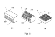
- the inventive Variants of the piezoelectric motor friction elements in Form of strips, chopsticks, pyramidal elements, or conical, cylindrical, semi-spherical elements Oxide ceramics, metal ceramics or as a composite with others Materials are made.
- Friction elements in the form of strips or sticks can Have transverse grooves that allow the between the Friction element and the oscillator arising reduce mechanical stresses and beyond a bending of the functional surface of the friction element to avoid.
- the friction elements have a single or multi-layer structure.
- layers can be the one- or multi-layer structure of the friction elements parallel to the side surfaces of the piezoelectric Be arranged oscillator.
- Such an arrangement of the layers of the friction elements allows the friction elements with a maximum possible area of the friction contact, which in is capable of compared to that of the prior art known embodiments of a piezoelectric Oscillator, motor or actuator significantly higher Transfer forces.
- piezoelectric motor can be single or multi-layer Layer structure of the friction elements in their entirety or partially perpendicular to the side surfaces of the Piezoelectric oscillator can be arranged.
- a such arrangement of the layers of the friction elements allows maximum suppression of parasitic and thus unwanted vibrations that occur during engine operation arise in the friction elements.
- piezoelectric Motors are the layers of single or multi-layer Structure cylindrical, conical or semi-spherical designed friction elements accordingly and arranged concentrically. Such a layer arrangement allows the piezoelectric oscillator to be minimal stressful design of the friction elements.
- the piezoelectric Motors have the layers within the one - or multilayer structure of the friction elements different modulus of elasticity. This variant of the Laying the friction elements enables optimal Adjustment of the friction elements of the piezoelectric Motors to the piezoelectric oscillator.
- the wear-resistant layer has multilayer friction elements of piezoelectric Motors of the friction element have a modulus of elasticity, by the wear resistance and mechanical strength its functional surface is determined while a connecting layer of the friction element by a Elasticity module is marked, the elasticity module the piezoelectric ceramic of the oscillator is adjusted. This creates an optimal acoustic Matching the friction element with the piezoelectric Allows oscillator.
- the wear-resistant layer of the multilayer structure of the friction elements expediently has an elastic modulus which is determined by the required wear and mechanical strength of its functional surface, while the properties of the damping layer are determined by the dynamic stability of the wear-resistant layer be determined. This achieves the maximum possible dynamic stability of the friction elements.
- piezoelectric motors with a two- or multi-layer structure of the friction elements can be a porous material as the connecting layer of the Friction element are provided, which increases the connection strength of the friction element with the surface of the piezoelectric oscillator is increased.
- the porosity of the materials within the layer structure the friction elements can in this embodiment be designed variably. All layers can be complete or partially made of a porous material with a variable porosity exist. Are particularly useful Designs of piezoelectric motors with a multilayer structure of the friction elements, in which the connecting layer has a maximum porosity and the wear-resistant layer is not porous. A such embodiment of the friction elements enables Cracks caused by mechanical stresses within the Avoid friction element caused.
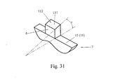
- This function surface can have friction elements be inclined to the side surface on which the friction elements are located, whereby the Coupling force between the friction elements and the Friction layer increased.
- the functional surface of the friction elements a triangular concave or convex shape, round have concave or convex shape
- the functional surfaces of the friction elements along the resonance length of the piezoelectric oscillator are arranged. This Variants of the functional surfaces of Friction elements increase the available area of the Frictional contact.
- the friction elements of the piezoelectric according to the invention Motors can be used in one embodiment an organic substance, e.g. an adhesive on the base of epoxy resin, with the surface of the piezoelectric Be connected to the oscillator, causing the Manufacturing technology of the piezoelectric motor simplified.
- an organic substance e.g. an adhesive on the base of epoxy resin
- the piezoelectric motor there is another embodiment of the piezoelectric motor the possibility of the friction elements by means of a fabric with the surface of the to connect piezoelectric oscillator, the one cohesive bond with the material of the oscillator received.
- a fabric with the surface of the to connect piezoelectric oscillator, the one cohesive bond with the material of the oscillator received.
- This variant of the connection between the surface of the piezoelectric ceramic and the friction elements allows a maximum Joint strength.
- Motors can cover all pores of the friction elements or part of it may be filled with a substance that the friction element with the surface of the piezoelectric Oscillator connects, which also creates a results in increased connection strength.
- the friction elements themselves can also be used as Glass strips run on the surface of the piezoelectric oscillator are melted. Thereby the manufacturing technology of Friction.
- the friction elements are manufactured as glass strips, can do this with powder of a wear-resistant fabric be replenished.
- powdered Aluminum oxide, zirconium oxide, tungsten carbide, titanium carbide or another similar substance can be used. This will the wear resistance of the friction elements increases.
- piezoelectric motor is an embodiment with the piezoelectric oscillator limiting elements provided a shift towards his Prevent resonance length.
- piezoelectric motor can preventing the displacement of the oscillator as mechanical resonators are used whose resonance frequency the oscillation frequency of the piezoelectric oscillator matches during engine operation. This will reduce the mechanical losses.
- Motors is the piezoelectric oscillator with equipped with at least one fixing element that is rigidly connected to the oscillator.
- the fixing ones Elements thus allow a rigid attachment of the piezoelectric oscillator.
- the fixing Elements on at least one of the side surfaces of the Piezoelectric oscillator arranged, preferably on the positions of the vibration minima along the resonance length of the oscillator vibrating standing acoustic longitudinal wave.
- Such an arrangement of the fixing Elements enables a frontal fixation of the piezoelectric Oscillator.
- Piezoelectric motors are the fixing elements at least on one of the main surfaces of the piezoelectric Arranged oscillator, preferably on the Set vibration minima towards the Resonance length of the oscillating oscillating standing acoustic longitudinal wave.
- Such an arrangement of fixing elements enables lateral fixing of the piezoelectric oscillator.
- Motors have the fixing elements the shape of a rectangular prism, triangular prism, semi-cylindrical Prism or the like other prismatic Shapes on, it being possible to use them as conical Elements, pyramid-shaped elements, semi-spherical Elements or as rectangular elements with profile grooves or protruding parts, as cylindrical step elements or designed as round elements with profile holes.
- the corresponding design of the fixing Elements enables reliable attachment of the piezoelectric oscillators.
- Piezoelectric motors are made up of fixing elements made of a material whose modulus of elasticity is the same or a little larger than the elastic modulus of the is piezoelectric ceramic, in particular made of oxide ceramic. Such a design ensures high strength of the fixing elements.
- the fixatives exist Elements made of a material whose modulus of elasticity small compared to the elastic modulus of the piezoceramic piezoelectric oscillator is.
- This design version the fixing elements enables a reduction the between the fixing element and the Mechanical stresses arising from the oscillator.
- the fixing elements can also be made of the same piezoceramic type be made, like the piezoelectric Oscillator. This creates an optimal acoustic coupling of the fixing elements to the oscillator. moreover can also be any fixing element or a part of one porous material. So that in fixing element resulting acoustic vibrations reduced.
- the fixing elements as components of the invention piezoelectric motor can be made using a organic adhesive with the surface of the piezoelectric Oscillator are connected. This makes it easier the manufacturing technology of the engine.
- Motors can at least fix the elements on one of the side surfaces of the piezoelectric Oscillator can be arranged, especially at the points the vibration minima in the direction of the resonance length of the Oscillator vibrating standing acoustic longitudinal Wave. This is an arrangement of the fixing Allows elements in the form of a forehead fixation.
- Piezoelectric motors are at least fixing elements on one of the main surfaces of the piezoelectric Arranged oscillator, in particular on the Set the vibration minima towards the Resonance length of the oscillator oscillating standing longitudinal wave.
- piezoelectric motor can fix the elements in fixed support beams can be set up. This will make one particularly stable fixation of the piezoelectric Enables oscillator.
- the fixed Support beams are made in the form of flat springs. As a result, those created by the support beam mechanical losses reduced.
- the driven element of the piezoelectric motor is generally slidably mounted. This enables longitudinal movements of the driven element.
- the displaceably mounted driven element is designed as a rectangular platform, a frame or as a bar with a rectangular, polygonal, round cross section or as a tube. This results in a wide range of design options for a piezoelectric linear motor.
- the driven element can be rotatably supported become.
- Such a motor construction enables one Rotational movement of the driven element.
- the driven element can take the form of an element Cylinder, a disc, a hollow cylinder or one Own ring.
- the mentioned construction forms of the driven element enable the construction of different variants of a piezoelectric rotary motor.
- Piezoelectric motors are available as a design the friction element is rectangular, round, elliptical or similar damping holes provided that a Propagation of acoustic waves whose frequency is the same the frequency of the piezoelectric oscillator during an engine operation or its harmonics, in Prevent friction element. This will be an improvement of the frictional contact of the motor.
- the thickness of which is expediently at least five times less than the resonance height of the piezoelectric Oscillator is the amplitude of longitudinal acoustic vibrations, that arise in the friction layer to reduce as sustainably as possible.
- the thickness of the one under the friction layer Friction element must have a greater value than that Have resonance height of the piezoelectric oscillator, by the amplitude of those created in the driven element reduce acoustic bending vibrations.
- a thin damping layer be inserted from a viscous organic or a porous non-organic material or as Composite of the same exists to the acoustic coupling between the friction layer and the driven elements to reduce.
- the piezoelectric motor according to the invention can be made from at least two opposite piezoelectric Oscillators and at least two on opposite Friction layers arranged on the sides of the driven element admir on stabilizing the camp To be able to do without longitudinal movement.
- the piezoelectric according to the invention Motor in a special embodiment from at least three piezoelectric oscillators and at least three, arranged parallel to each other and at least in three Layers of friction layers.
- Motors with separate generators for longitudinal Waves is the electrical excitation source as one Two-channel power amplifier implemented. This consists of a first and a second channel, to a basic generator connected formation stages, as well as output power amplifiers, the electrically via adjustment levels with appropriate electrodes on the generator piezoelectric oscillator are connected. This generate acoustic longitudinal in the direction of the resonance length of the piezoelectric oscillator vibrating Waves, as well as acoustic longitudinal waves, which in Swing in the direction of the resonance level.
- the electrical Excitation source as a single channel power amplifier built, the one connected to the basic generator Forming stage and an output power amplifier comprises of an adjustment stage and an electrode commutator with the electrodes of the corresponding composite Piezo generator is connected.
- the output power amplifiers are as bridge power amplifiers constructed, each of which is two half bridges includes.
- the formation levels contain two excitation channels said half-bridge power amplifier, where one of the excitation channels with a phase control element is equipped and contains a phase control input. This will regulate the speed of movement of the driven element allows.
- the motor according to the invention is a Equipped with a signal level converter, the Output with the phase control input one Phase control element is connected. This enables one Control the speed of movement of the driven Element by means of a linear electrical signal.
- the invention is Motor with a demodulator of a pulse width modulated Signal equipped, the output with the phase control input of the phase control element is connected. This will control the speed of movement of the driven element by means of a pulse width modulated Signal enables.
- an embodiment of the invention Possible with a stage detector for the zero position, its measuring input to the input of the signal level converter or to the output of the demodulator of a pulse width modulated Signal is connected.
- the exit of the stage detector with the input of a reversing switch or with the control input of an electrode commutator connected.
- This design of the engine reversing the driven element is possible.
- the basic generator is equipped with a frequency control input. Frequency control of the basic generator is possible in this motor variant.
- an embodiment of the motor according to the invention is provided with a phase detector which comprises a first and a second phase input and an output, the output of the phase detector being connected to the frequency control input of the basic generator, the first phase input being electrically connected to the electrodes of the same name of the corresponding generator of acoustic connected longitudinal waves and the second phase input is electrically connected to one of these waves. This enables automatic frequency control of the basic generator.
- separate generators of acoustic waves is a sensor designed as a thin piezoceramic plate that is on their large surfaces contains electrodes, and the acoustically coupled on the surface of the piezoelectric Oscillators, especially in the places of the largest mechanical stresses of acoustic in piezoelectric Oscillator vibrating longitudinal wave is attached. This is a determination by means of the sensor the mechanical resonance of the by separate generators excited oscillator possible.
- the sensor is primarily generators of acoustic waves in the form of two thin piezoceramic plates, which contain electrodes on their wide surfaces and the acoustically coupled on the surface of the piezoelectric Oscillators are attached.
- Both sensor parts are connected via a sensor signal commutator to the second input of the phase detector connected. Its control input is electrical with the Control input of the reversing switch connected.
- the sensor also enables determination the strength of the mechanical resonance of the piezoelectric Oscillator.
- the proposed motor can use a coordinate or Movement parameter sensor of the driven element equipped be the electrically with a processor controlled Controller of the parameters measured by the sensor connected and its output to the signal level converter or the demodulator of a pulse width modulated signal connected is. This is a regulation of the coordinates or Movement parameters of the driven element possible.
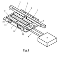
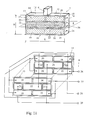
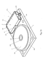
- the motor consists of a housing 1, in which the bearing for the longitudinal movement 2 of the driven element 3 with the friction layer 4 is set up.
- the driven element 3 is designed as a bar with a rectangular cross section.
- the driving element 5 is also arranged with the friction element 6, which is in frictional contact with the friction layer 4.
- the driving element 5 is designed as a monolithic plate-shaped piezoelectric oscillator 7, which is electrically connected to the electrical excitation source 9 via the outputs 8.
- the oscillator 7 shows one of the design variants of the piezo oscillator 7. Its main part is the rectangular piezo element 12.
- the oscillator 7 has a first 13 and a second 14 main surface, a first 15 and a second 16 side surface, a first 17 and a second 18 end surface, the resonance length L and the resonance height H.
- the piezoelectric ceramic of the piezo element 12 is polarized normally to the main surfaces 13, 14 of the oscillator 7, as is indicated in FIG. 2 and further by arrows.
- the resonance length L is equal to the wavelength ⁇ of a wave propagating along the length of the oscillator 7.
- the resonance height H of the oscillator 7 is equal to half a wavelength ⁇ of a wave propagating along the height of the oscillator 7.
- the first electrode group includes the electrodes 19, 20 and the second the electrodes 21, 22.
- the configuration of the electrodes 19, 20, 21, 22, their arrangement and electrical wiring is shown in FIG. 2, lower part.
- the electrodes 19, 20 of the first electrode group and the piezoelectric ceramic located between them form the generator 24 of an acoustic longitudinal wave which propagates along the resonance length L of the piezoelectric oscillator 7.
- the electrodes 21, 22 of the second electrode group and the piezoelectric ceramic lying between them form the generator 25 of an acoustic longitudinal wave which propagates along the resonance height H of the piezoelectric oscillator 7.
- this wave is a wave constant in sign along the resonance length L of the oscillator 7.
- the electrodes 19, 20 of the first electrode group are arranged in the edge regions of the main surfaces 13, 14 of the oscillator 7, symmetrically with respect to the plane of symmetry S, which passes through the center of the resonance height of the oscillator 7 and is perpendicular to the main surfaces 13, 14.
- the electrodes 21, 22 of the second electrode group are arranged in the central areas of the main surfaces 13, 14 of the oscillator 7, symmetrically with respect to the plane of symmetry S, which passes through the center of the resonance height of the oscillator 7 and is perpendicular to the main surfaces 13, 14.
- each of the electrodes 19, 20, 21, 22 is equipped with connections 26, 27, 28, 29 which form the connection group 8.
- the connections 19, 20 serve to supply excitation voltage to the generator of the acoustic waves 24.
- the connections 28, 29 serve to supply excitation voltage to the generator of the acoustic waves 25.
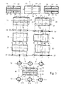
- Fig. 3 explains the operation of the oscillator 7 of the engine variant under consideration.
- the principle of the independent excitation of acoustic waves in the oscillator 7 is used to explain the mode of operation. According to this principle, due to the small oscillation amplitude, the oscillator 7 can be represented as two independent oscillators shown in items 30, 31, each of the two only containing one generator of acoustic waves.
- the oscillator shown in pos. 30 contains only the generator 24 of the acoustic wave that propagates along its resonance length L and that in pos. 31 only the generator 25 of the acoustic longitudinal wave that propagates along its resonance height H.
- the oscillator shown in pos. 30 has the waveforms shown in pos. 32, 33.
- the points lying on its side surfaces 15, 16 along the axes a, b, c are at oscillation speed maxima and they move along the longitudinal paths shown in pos. 34, 35.
- the points lying on its side surfaces, along the axes n, m are in vibration velocity minima and have only a small transverse amplitude of the vibrations.
- the oscillator shown in pos. 31 has the waveforms shown in pos. 36, 37.
- the points lying on its side surfaces 15, 16 along the axes d, p, e, q, f move along the transverse paths shown in pos. 38, 39.
- This acoustic wave is sign-constant along the resonance length L of the oscillator.
- the friction element 6 shows elliptical movement phases of the friction element 6 mounted on one of the side surfaces 15 or 16 along one of the axes ad, be, cf. Pos. 43 - phase of the forward pressure, phase of the forward movement - Pos. 44, phase of the back pressure - Pos. 45, phase of the back movement - Pos. 46.
- the direction of movement of the friction element 6 is determined by the sign of the vibration velocity maxima of the acoustic wave, which propagates along the resonance length L of the oscillator 7.
- the friction elements 6 are attached at the points at which the points of the surfaces 15, 16 have the same direction of movement on closed tracks.
- the resonance length L is an integer multiple of ⁇ .
- Item 51 of FIG. 8 discloses a construction variant of the oscillator 7 in the form of the cylinder part 52, the Resonance length L is equal to ⁇ .
- Items 53, 54 show arrangement variants the friction elements 6 on the side surfaces 15, 16 with the oscillator 6 in the form of the cylinder part 52nd
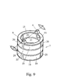
- FIG. 9 shows a design variant of the oscillator 7 in the form of the cylinder 55, the resonance length L of which is equal to 2 ⁇ .
- Such an oscillator is composed of two parts 52 (see FIG. 8), each part having a resonance length L equal to ⁇ .
- the two friction elements 6 have an opposite direction of movement.
- Fig. 11 shows the piezoelectric oscillator 7 with the Generator 56, which is along its resonance length L. sign-variable acoustic standing wave that generates propagates along its resonance height H.
- Fig. 11, lower Part shows a configuration variant of the electrodes 19, 20 and 21, 22 of the generators 24 and 56, their arrangement the main surfaces 13, 14 of the oscillator 7 and their electrical wiring with connections 26, 27 and 28, 29th
- the oscillator shown in pos. 30 Fig. 12 contains only the generator 24 and that in pos. 58 contains only the generator 56.
- the oscillator shown in pos. 30 has the waveforms shown in pos. 32, 33.
- the points lying on its side surface 15, 16 along the axes a, b, c are in oscillation speed maxima and they move along the longitudinal paths shown in pos. 34, 35.
- the points lying on its side surfaces, along the axes n, m, are in vibration velocity minima and have only a small transverse amplitude of the vibrations.
- the oscillator shown in pos. 58 has the waveforms shown in pos. 59, 60.
- the points lying on its side surfaces 15, 16 along the axes d, e, f move along the transverse paths shown in pos. 61, 62.
- the acoustic wave generated by the generator 56 is sign-variable along the resonance length L of the oscillator 7. With such a wave, the sign of the deformation of the side surfaces 15, 16 changes along the resonance length L.
- the friction elements 6 can be set up on the side surfaces 15, 16 in all oscillation speed maxima of an acoustic wave that propagates along the resonance length L of the oscillator 7. Points lying along the axes np, mq do not vibrate. They are well suited for fastening fixing elements 10.
- the resonance length L. is an integer multiple of ⁇ .
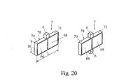
- FIG. 17 shows a design variant of the oscillator 7, the electrodes 19 (see FIG. 2) of which belong to the surface 13, are combined with a part of the electrode 21 and together form the first combined electrode 66. Electrodes 20 belonging to surface 14 are united with part of electrode 22 and together form the second united electrode 67. Electrodes 20 belonging to surface 13 are united with part of electrode 21 and together form the third United electrode 68. Electrodes 19 belonging to surface 14 are united with part of electrode 22 and together form the fourth united electrode 69.
- the group of combined electrodes 66, 67 with the piezoelectric ceramic in between forms the first composite generator 70 of acoustic waves and the group of combined electrodes 68, 69 with the piezoelectric ceramic in between forms the second composite generator 71 of acoustic waves.
- item 72 shows a configuration variant of the combined electrodes 66, 67, 68, 69 and their arrangement on the surfaces 13, 14 of the oscillator 7.
- the electrical excitation source 9 be equipped with an electrode commutator 80.
- Fig. 19 explains the operation of the oscillator 7 with the composite generators of the acoustic waves 70, 71.
- Pos. 78 Fig. 19 shows an oscillator with a generator of acoustic waves 70, which is located in the left part of the oscillator. When this generator is excited, a standing acoustic wave is generated in the oscillator and propagates along the resonance length L. When this wave propagates, the oscillator 7 has the waveforms shown in pos. 81, 82. The points lying on the side surfaces 15, 16 along the axis b1 have the movement paths shown in pos. 83, 84.
- an acoustic longitudinal wave is generated in the oscillator shown in item 78, which propagates along the resonance height H.
- the oscillator 7 has the waveforms shown in pos. 85, 86.
- the points lying on the side surfaces 15, 16 along the axis e have the movement paths shown in items 87, 88. Since these waves propagate in the oscillator at the same time, there is a movement superposition of the points lying on the surfaces 15, 16 along the axes b1e, which is shown in item 89. As a result, these points move along the closed paths shown in pos. 90, 91 and indicated by arrows.
- An oscillator is shown in pos.
- the oscillation phase of this wave is in phase with the wave generated by generator 70.
- Pos. 96 shows a movement superposition of the points lying on the surfaces 15, 16 along the axis b2e as a result of the propagation of two waves in the oscillator 7, which are generated by the generator 71.
- the trajectories of these points are shown in pos. 97, 98.
- the dots have an opposite direction of movement compared to the excitation of the generator 70.
- the trajectories are shown in pos. 90, 91 and 97, 98 and can be seen as ellipses at first approximation.
- the surfaces 15, 16 along the axes b1, b2 are the fastening points of the friction elements 6.
- Points along the axes np, mq on the surfaces 15, 16 are located in the vibration velocity minima of the wave propagating along the resonance length L of the oscillator 7 and are optimally suitable for fastening the fixing elements 10.
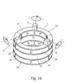
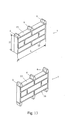
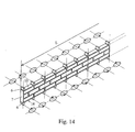
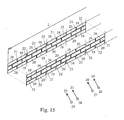
- 20 shows two oscillators 7 with generators 70, 71, the resonance length L of which is ⁇ .
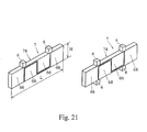
- the oscillators 7 shown in FIG. 21 have one Resonance length L is 2 ⁇ .
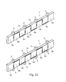
- Those shown in Fig. 22 Oscillators 7 have a resonance length L equal to 4 ⁇ .
- a piezoelectric oscillator that has two or contains several oscillators 7, which are so together are connected that a common electromechanical Resonator 99 is formed.
- a connection can performed using a solid organic glue e.g. an adhesive based on the epoxy resin or by sintering.
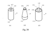
- the friction elements can be manufactured as strips 100, as rods or prisms 101, 102, 103, as pyramid-shaped elements 104, 105, as semi-spherical elements 106, as cylindrical elements 107, 108, 109, as conical elements 110 or as semi-spherical elements 111.
- Each friction element 6 has the functional surface 112 with which it is in frictional contact with the friction layer 4 and a connection surface 113 with which it is connected to the side surface 15 or 16 of the oscillator 7.
- the friction elements 6 are made of a hard, wear-resistant material, for example oxide ceramics, metal ceramics, or their compositions with other materials. Special grades of hard wear-resistant plastics can also be used.
- friction elements 6 which have transverse grooves 117.
- the transverse groove 117 can be provided both from the side of the connecting surface 113 item 114 and from the side of the functional surface 112 item 115. They can also be arranged perpendicular to each other, item 116.
- the friction elements 6 can have a two- or multi-layer structure, as shown in pos. 118, 119, 120, 121, 122, 123 of FIG. 28. Each layer of this structure is arranged parallel to the side surfaces 15, 16 of the oscillator 7.
- the upper layer 124 of this structure is a wear-resistant layer. It contains the functional surface 112.
- the lower layer 125 of this structure is a connecting layer. It contains the connecting surface 113.
- the layers 124, 125 and the layer in between can have a different modulus of elasticity.
- the wear-resistant layer 124 can have a modulus of elasticity, which is determined by the wear resistance and mechanical strength of the functional surface 112, and the connecting layer of the friction element can have a modulus of elasticity that is almost equal to the modulus of elasticity of the piezoelectric ceramic of the oscillator 7.
- the friction elements 6, which are shown in pos. 126, 127, 128, FIG. 29, have the layers 129, 130, which are arranged perpendicular to the side surfaces 15, 16 of the oscillator 7.
- the layers 129 are wear-resistant layers and the layers 130 are damping layers.
- the damping layers 130 ensure dynamic stability of the wear-resistant layers.
- the wear-resistant layer 129 can have an elastic modulus, which is characterized by wear resistance and strength of its functional surface, and the damping layer 130 can have an elastic modulus, which is determined by the dynamic stability of the wear-resistant layer 129.
- Layer 134 is a friction layer. It contains the functional surface 112.
- the layer 135 is a damping layer. It ensures dynamic stability of the friction layer 134.
- the layer 136 is a protective layer.
- the layers 124, 125, the layers 129, 130 lying between them and the layers 134, 135, 136 can be produced from monolithic materials and can be connected to one another, for example, by sintering.
- the connecting layer 125 of a two-layer or multi-layer structure of the friction elements 6 can be produced from a porous material.
- part of the two- or multi-layer structure of the friction elements 6, which is shown in pos. 121, 122, 123 Fig. 28, can consist of a porous material with variable porosity.
- the connecting layer 124 can have a maximum porosity, the wear-resistant layer 125 being non-porous.
- the damping layers 130, 135 can also be produced from a porous material.
- this surface can be designed as an inclined surface 137, as shown in FIG. 31.
- the inclined functional surface 137 is arranged at an angle r to the side surface 15 or 16 on which the friction elements 6 are attached.
- the functional surface 112 of the friction elements 6 can have the shape shown in FIG. 32, items 138, 139, 140, 141, 142, 143. It can have the triangular concave (143) or convex (144) shape, the round concave (145) or convex (146) shape or a rib-shaped (147, 148) shape.
- the ribs or grooves 149 of the functional surface 112 are arranged along the resonance length L of the piezoelectric oscillator 7.
- the functional surface 112 can also have another similar shape.
- the friction elements 6 can be connected to the surfaces 15, 16 of the piezoelectric oscillator 7 by means of an organic material, for example with epoxy resin.
- the friction elements 6 can also be connected to the surface of the piezoelectric oscillator 7 with a material which forms a chemical bond with the piezoelectric ceramic, for example by means of lead-containing, low-melting glass. All pores of the friction elements 6 or a part thereof can be filled with a material that connects the friction element 6 to the surfaces 15, 16 of the piezoelectric oscillator 7.
- the transverse groove 17 can advantageously be filled with a sound-absorbing material.
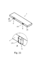
- the friction elements 6 can be manufactured as glass strips 150 which are melted onto the side surface 15 or 16 of the piezoelectric oscillator 7, as is shown in FIG. 33.
- the friction elements manufactured as glass strips 150 can be coated with powder of a wear-resistant substance, for example with powder of aluminum oxide, zirconium oxide, tungsten carbide, titanium carbide or another similar substance.
- Fig. 34 shows a piezoelectric motor with special brackets 152 of the piezoelectric oscillator 7, which prevent its displacement in the direction of its resonance length L.
- the driven element 3 is designed as a frame 154 comprising the driving element 5.
- FIG. 35 shows a design variant of the piezoelectric motor in which the elements 155 preventing the displacement of the oscillator serve as mechanical resonators, the resonance frequency of which corresponds to the oscillation frequency of the piezoelectric oscillator 7.
- the driven element 3 can be realized in the form of a cylinder or a disk 156, which is set up on the shaft 157 in the bearing of the rotational movement 158.
- the piezoelectric oscillator 7 can be equipped with at least one fixing element 10, which is rigidly connected to the oscillator.
- the constructions of the fixing elements 10 are shown in items 159 to 170 in FIG. 36.
- the fixing elements can be designed in the form of rectangular prisms (159), triangular prisms (160), semi-cylindrical prisms (161) or conical elements (162), pyramid-shaped elements (163), semi-spherical elements (164), rectangular elements with profile grooves (165) or protruding elements (167), as cylindrical step elements (168), round elements with profile bores (169, 170) or other similar elements.
- the fixing elements 10 can be produced from a material whose modulus of elasticity is equal to or slightly greater than the modulus of elasticity of the piezoelectric ceramic of the piezoelectric oscillator 7, for example of oxide ceramic.
- the fixing elements 10 can consist of a material whose modulus of elasticity is much smaller than the modulus of elasticity of the piezoceramic of the piezoelectric oscillator 7, for example of special types of plastic.
- the fixing elements 10 can be manufactured from the same type of piezo ceramic as the piezoelectric oscillator 7.
- Each fixing element 10 or one of its parts can be made of a porous material.
- the fixing elements 10 can be connected to the side surfaces 15, 16 of the piezoelectric oscillator 7 by means of a rigid organic material, for example an adhesive based on epoxy resin.
- the fixing elements 10 can be connected to the side surfaces 15, 16 of the piezoelectric oscillator 7 by means of a material, which enters into a chemical bond with the piezoelectric ceramic or an intermediate layer provided on the side surfaces 15, 16 and with the material of the fixing element, for example by means of leaded, light-melting glass.
- FIG. 37 shows the piezoelectric oscillator 7 with the fixing elements 10 attached to it, which are designed as cylindrical step-shaped elements, as shown in item 168 FIG. 35.
- 38 shows a variant of the oscillator 7, in which the fixing elements 10 are designed as resonance bending plates or beams 171.
- 39 shows a construction variant of the proposed motor, in which the fixing elements 10 are set up in fixed support beams 172.
- the oscillator 7 is fastened to the friction layer 4 with the aid of the fixing elements 173, which are produced as rings made of rubber or another similar material.
- the driven element 3 is designed in the form of a rectangular platform 174, on the side surface of which the friction layer 4 is arranged.
- the friction layer 4 is made as a strip of oxide ceramic or another similar material, for example zirconium oxide, tungsten carbide, titanium carbide, silicon oxide.
- the thickness of the friction layer S (see FIG. 39) can be at least five times smaller than the resonance height H of the piezoelectric oscillator 7.
- the body thickness D of the friction element 3 located under the friction layer 4 can be greater than the resonance height H of the piezoelectric oscillator 7.
- the driven element 3 can be made of metal, ceramic or plastic.
- each friction layer 4 has a functional surface 179 which is in frictional contact with the friction elements 6. This functional surface can be smooth or have another shape, as shown in FIG. 40. 41 items 180 to 185 show different variants of the functional surfaces 179.
- the functional surface 179 can have the triangular concave (180) or convex (181) shape, round concave (182) or convex (183) shape or a rib-shaped (147, 148 ) Have shape.
- the functional surface 112 can also have another similar shape.
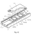
- 42 shows a design variant of the proposed motor, in which the two friction layers 4 are fastened to the housing 1 opposite and at an angle r to the side surfaces 15, 16 of the oscillator 7.
- the oscillator 7 has four friction elements 6, which are arranged in pairs on the side surfaces 15, 16.
- the friction elements 6 are also designed with the inclined functional surfaces 137 and are arranged at an angle r to the side surfaces 15, 16 of the oscillator 7.
- the fixing elements 10 (159) of this motor variant are fastened with one of their sides on the main surface 13 and with the second on the driven element 3, which is designed as a rectangular platform 174.
- the oscillator 7 is pressed onto the friction layers 4 with the aid of the magnets 186, which are fastened on the driven element 3.
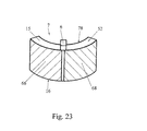
- 43 shows a design variant of the proposed motor, in which the oscillator 7 is designed as a cylinder part 52.
- This motor has the driven element 3, which is designed as a hollow cylinder or ring 187.
- the outer surface of the driven member is provided with a gear 188.
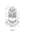
- the oscillator 7 has two friction elements 6 and the driven element 3, which is designed as a frame 189, which contains two parallel friction layers 4 lying in one plane.
- the oscillator 7 has three friction elements 6.
- Its driven element 3 is designed in the form of a ring which is pressed onto the oscillator 7 with the aid of the elastic intermediate layer 190 and the flange 191 fastened to the shaft 192.
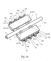
- 46 shows a linear motor which includes two opposing oscillators 7 and two friction layers 4 located on the two opposite sides of the driven element.
- the driven element 3 can be made from a beam with a round cross-section or from a tube 193, as shown in FIG. 46.
- the outer beam surface 193 can perform the function of the friction layer 4.
- the pressing of the oscillator 7 against the friction layer 4 can be ensured in this motor with the aid of the rigid support beams 172, which are made as a flat spring 194.
- 47 shows a construction variant of the motor, which includes at least three piezoelectric oscillators 7 and at least three friction layers 4, which are arranged parallel to one another and lie at least in three planes.
- the driven element 3 can be designed as a beam 195 with a triangular or polygonal cross section, as shown in FIG. 47. Fig.
- the electrical excitation source 9 is constructed as a two-channel power amplifier 196, with the first 197 and with the second 198 channel.
- Each channel (197, 198) includes the formation stage 199, whose input 200 is connected to the output 201 of the basic generator 202.
- channels 197, 198 include output power amplifier 203, whose outputs 204, 205 are electrically connected to inputs 206, 207 of adaptation stage 208.
- the outputs 209, 210 of the adaptation stage 208 of the channel 197 are electrically connected to the connections 26, 27 of the generator of acoustic longitudinal waves 24 of the oscillator 7.
- the outputs 209, 210 of the adaptation stage 208 of the channel 198 are electrically connected to the connections 28, 29 of the generator of acoustic longitudinal waves 25 (or 56) of the oscillator 7.
- the electrical excitation source 9 is constructed as a single-channel power amplifier 211, with the channel 197 (or 198), which includes the formation stage 199, whose input 200 is connected to the output 201 of the basic generator 202.
- Channel 197 (or 198) also includes output power amplifier 203, which has its outputs 204, 205 electrically connected to inputs 206, 207 of matching stage 208.
- the output 209 of the adaptation stage 208 is electrically connected to the connection 79 of the common electrode 78 of the oscillator 7.
- the second input 210 of the adaptation stage 208 is connected to the input 212 of the electrode commutator 80.
- the outputs 213 and 214 of the electrode commutator 80 are connected to the electrodes 66 and 68 of the composite generators 70 and 71 of the oscillator 7.
- the electrode commutator 80 has the control input 215.
- the proposed invention provides a motor variant in which each of the output power amplifiers 203 of the channel 197 or 198 is constructed as a bridge power amplifier 216 (see FIG. 50), which include the first half-bridge power amplifier 217 with the output 204 and the second half-bridge power amplifier 217 with the output 205 on which the voltages U1 and U2 are effective. Both half-bridge power amplifiers 217 include transistor switches 218.
- the formation stages 199 consist of two excitation channels 219, 220 of the half-bridge power amplifier 217.
- Each of the excitation channels 219, 220 includes the drivers 221 and the formation stage 222.
- one of the excitation channels, for example channel 220 can be equipped with the signal phase control element 223, on the phase control input 224 of which the control voltage Ust is effective.
- one of the channels 197, 198 can be equipped with the reversing switch 225, on the control input 226 of which the control voltage etc. acts (see FIG. 50).
- connection 227 is connected to ground or the common zero potential of the excitation source 9.
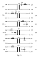
- Items 228 to 233 of FIG. 51 show possible variants of the adaptation elements 208, which include the summing transformer 234, the compensation coil 235 and the resonance capacitor 236.
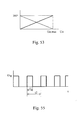
- Items 237 to 239 of FIG. 52 show diagrams of the electrical voltages U1, U2, U31 (U32).
- the voltage U1 is present between the output 204 and the common potential 227 of the first half-bridge amplifier 217.
- the voltage U2 is present between the output 205 and the common potential 227 of the second half-bridge amplifier 217.
- These voltage profiles have a rectangular shape.
- the voltages U31 or U32 are effective at the outputs 209 and 210 of the adapter 208. This voltage has a sinusoidal shape.
- the voltages U1 and U2 are shifted from each other by the phase shift angle ⁇ p.
- the angle ⁇ p is determined by the signal phase control element 223 and changed by the control voltage Ust active at its control input 224.
- 53 shows the desired dependence of the phase shift angle Phasenp on the control voltage Ust of the signal phase control element 223 by the continuous line. Another possible dependency is shown using the dotted line.
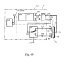
- 54 shows a block diagram of the proposed motor, which is equipped with a converter 240 of the control signal Usg, which contains the signal input 241 and the output 242 of the control voltage Ust, and which is connected to the phase control input 224 of the phase control element 242.
- the converter 240 can be implemented as a level converter of the signal voltage Usg into the voltage Ust.
- the converter 240 is a demodulator of a pulse-width-modulated signal, which converts the signal-width ratio t1 / t2 into the control voltage Ust.
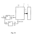
- the diagram of the plus-width modulated signal is shown in FIG. 55.
- the considered variants of the proposed motor can be equipped with a zero position step detector 243, the measuring input 244 of which is connected to the input 241 of the converter 240. Its input 245 can be connected to the control input 226 of the reversing switch 225 or to the control input 215 of the electrode commutator 215 (see FIG. 54).
- the switchover voltage etc. is active at the output 245 of the stage detector 243.
- Fig. 56 items 246, 247, the desired transfer characteristics of the converter 240 are shown with continuous lines.
- Fig. 56 item 249 possible control characteristics of the movement of the driven element of the proposed motor 3 are shown by the continuous line and the dotted line.
- Fig. 57 Pos. 250 251 possible design variants of the sensor of the mechanical stresses of an acoustic longitudinal wave are shown, which propagate in the oscillator 7.
- the sensor 252 can be designed as a thin rectangular or round piezoelectric plate (not shown), with the electrodes 253, 254 on their wide surfaces and with the polarization directed perpendicular to the electrodes, as disclosed in item 250.
- the sensor 252 can be designed as two thin piezoceramic plates, which are acoustically fastened on one of the main surfaces 13, 14 of the piezoelectric oscillator 7 at locations of greatest mechanical stresses, an acoustic longitudinal wave, which propagates along the resonance length of the oscillator, and whose points with a 180 ° signal phase shift of one of the power amplifier channels 197, 198 with respect to the signal of another have the same trajectories.
- the sensor plates are attached symmetrically at a distance of 1/4 L from the vertical y-axis on surfaces 13, 14 of the oscillator 7, as shown in FIG. 57, item 251.
- the acoustic attachment of the sensor 252 to the surfaces 13 or 14 of the oscillator 7 can be done by gluing to one of the electrodes 253, 254 of the sensor 252 with the aid of a hard adhesive based on the epoxy resin or by soldering to the corresponding electrode (19, 20, 66, 68, 78) of the oscillator 7.
- Pos. 255 shows a dependency of the voltage Us of the sensor signal and the dependence of the speed of movement V or speed N of the driven element 3 on the excitation frequency f of the oscillator 7.
- the basic generator 202 can be equipped with an excitation frequency control input 257 (see FIG. 59).
- the proposed motor can be equipped with the phase detector 258, which has the first 259, the second 260 phase input and the output 261.
- the first output 259 of the phase detector 258 can be connected to the electrode 253 of the sensor 252.
- the second output 260 is connected to the connection 26 of the electrodes 19 of the oscillator 7.
- the phase detector output must be connected to the frequency control input 257 of the basic generator 202, as shown in FIG. 59.
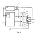
- 60 shows a block diagram of the design variant of the proposed motor with the sensor 252, which is made of two thin plates.
- This variant of the motor is equipped with the signal commutator of the sensor 262, which contains the first input 263, the second input 264, the output 265 and the control input 266.
- the first input 263 of the commutator 262 is connected to the electrode 253 of the first plate of the sensor 252 and its second input 264 is connected to the electrode 23 of the second sensor plate 252 and the output 256 is connected to the phase input 259 of the phase detector 258.
- the control input 266 of the commutator 262 is connected to the control input 215 of the electrode commutator 80.
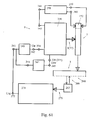
- 61 shows a block diagram of a design variant of the proposed motor, which is equipped with a coordinate or movement parameter sensor 267 of the driven element 3.
- the sensor 267 has the scale 268 and the reading device 269.
- the information output s of the sensor 267 is electrically connected to a processor-controlled controller 271.
- the output 272 of the processor-controlled controller 271 is connected to the input 241 of the converter 240.
- the operation of the proposed piezoelectric motor is based on simultaneous electrical excitation in the monolithic piezoelectric oscillator 7 of an acoustic longitudinal wave that extends along the resonance length L and an acoustic longitudinal wave that propagates along the resonance height H of the oscillator 7.
- An acoustic wave that propagates along the oscillator length L of the oscillator 7 is to be understood as a wave due to the propagation of which the particles of the oscillator 7 preferably oscillate in the direction of the oscillator length L. During the propagation, this wave is reflected on the two end surfaces 17, 18 of the oscillator 7, on the basis of which a standing wave is formed.
- An acoustic wave that propagates along the oscillator height H of the oscillator 7 is to be understood as a wave due to which the particles of the oscillator 7 preferably oscillate in the direction of the oscillator height H. During the propagation, this wave is reflected on the two side surfaces 15, 16 of the oscillator 7, due to which a standing wave results.
- the resonance length L of the oscillator 7 is the same or is an integer multiple of a wavelength of the acoustic standing wave propagating along the oscillator length L.
- the resonance height H of the oscillator 7 is half a wavelength of the acoustic standing wave propagating along the oscillator height H.
- the resonance length L and the resonance height H of the oscillator 7 are linked to the condition that the frequencies of the waves propagating in the oscillator are the same. This condition places certain limits on the geometric dimensions of the oscillator 7. Since the two waves generated in the oscillator are of the same type, the wavelengths are approximately the same if the frequency of this wave is the same, ie ⁇ . This means that the ratio L / H of the oscillator is approximately 2 or an integer multiple of 2, ie 4, 6, 8.
- the acoustic wave generated in the oscillator 7 and propagating along the resonance height H can be constant in sign and variable in sign along the resonance length L. In one design variant of the motor, two acoustic waves are excited in the oscillator 7 with the aid of two independent generators of the acoustic waves 24, 25 or 56.
- the difference between the generators 24, 25 and 56 lies in the configuration of the electrodes 19, 20 of the first electrode group and the second electrode group 21, 22, which form these generators, in the arrangement of these electrodes on the surface of the oscillator 7 and in their mutual wiring.
- the electrodes 19, 20 of the first electrode group are arranged in the edge regions of the main surfaces 13, 14 of the oscillator 7, symmetrically with respect to the plane of symmetry S, which passes through the center of the resonance height H of the oscillator 7. Due to the excitation in the oscillator 7, this configuration of the electrodes 19, 20 enables an acoustic longitudinal wave that propagates along the resonance length L.
- the electrodes 21, 22 of the second electrode group are arranged in the central regions of the main surfaces 13, 14 of the oscillator 7, symmetrically with respect to the plane of symmetry S, which passes through the center of the resonance height of the oscillator 7. Due to the excitation in the oscillator 7, this configuration of the electrodes 21, 22 enables an acoustic longitudinal wave that propagates along the resonance height H.
- the electrodes 19, 20 of the first electrode group can be connected to the electrodes 21, 22 of the second electrode group, so that the composite generators of the acoustic waves 70, 71 are formed.
- the generators 70, 71 simultaneously excite an acoustic longitudinal wave in the oscillator 7 which extends along the resonance length L and an acoustic longitudinal wave which propagates along the resonance height H of the oscillator 7. In all the cases considered, acoustic longitudinal waves are generated in the oscillator 7, which have no bending component.
- the electrical excitation of the generators 24, 25, 56, 70, 71 in the variants of the proposed motor takes place with the aid of the electrical excitation source 9, which provides a periodic one- or two-phase excitation voltage depending on the design of the oscillator 7.
- the excitation voltage is applied to the electrodes of the generators 24, 25, 56, 70, 71 given the acoustic waves and excites them. Because of this, in the oscillator 7 generated acoustic waves considered above. The impact of these waves on the friction elements 6 causes them to perform an elliptical motion.
- the elliptical movement of the friction element 6 causes a longitudinal movement of the driven element 6, in one direction or the other, depending on the phase shift between the acoustic waves propagating in the oscillator 7.
- 4 arranged on the side surface 15 or 16 moves due to the propagation of two acoustic longitudinal waves in the oscillator 7 along the elliptical paths shown in pos. 43, 44, 45, 46.
- This movement can be divided into four phases. 43.
- the friction element moves in the direction of the friction layer 4 and is pressed against it. A coupling takes place between the friction element 6 and the friction layer 4.
- the friction element transmits the force to the driven element 3 by the frictional forces and causes it to move.
- the friction element 6 goes back from the friction layer 4 and breaks off the friction contact.
- the friction element performs a backward movement.
- the friction elements 6 have an opposite direction of movement of their elliptical movement paths lying in two parallel planes, which enables use in linear motors.
- the friction elements 6 can be placed both on a side surface 15 or 16 and on the two surfaces simultaneously.
- the friction elements 6 have the same direction of movement of their elliptical trajectories, which lie in the three planes at an angle of 120 °.
- Such oscillators can be used in rotary motors.
- these grooves can be filled with a sound-absorbing material. In this case, parasitic vibrations that arise in parts of the friction elements 6 are damped.
- they can be manufactured as glass strips 151 which are melted onto the side surface 15 or 16 of the piezoelectric oscillator 7, as is shown in FIG. 33.
- Such friction elements can be applied to the oscillator 7 with the aid of screen printing technology with further thermal treatments.
- the friction elements 6 made as glass strips 151 can be filled with powder of a wear-resistant material, for example with powder of aluminum oxide, zirconium oxide, tungsten carbide, titanium carbide or another similar material.
- Fig. 34 shows two limiting elements 152 of the piezoelectric oscillator 7, which prevent its displacement along the resonance length L. These elements have to be made of plastic with a small coefficient of friction with respect to the piezoelectric ceramic, for example made of Teflon or from a material similar to it. In order to avoid jamming of the oscillator between the limiting elements, the distance between them is chosen to be somewhat larger than the resonance length L of the oscillator 7.
- the gap between the oscillator 7 and the limiting elements 152 (not shown in Fig. 34) must be approximately 0.05 ... 0.1 mm. Such a gap ensures that the friction element 6 is reliably pressed against the friction layer 4 by the elastic elements 135.
- the limiting elements 152 reliably keep the piezoelectric oscillator 7 from its longitudinal displacement within limits of the gap width.
- the driven element 3 can be designed in this and in other motor variants as a frame 154 comprising the driving element 5.
- 35 shows a motor variant in which the limiting elements 155 represent mechanical resonators, the resonance frequency of which corresponds to the oscillation frequency of the piezoelectric oscillator 7 when the motor is operating. These elements are made of elastic metal plates, which compress the oscillator 7 by insulating supports and prevent it from moving along the resonance length L. During engine operation, the limiting elements 155 resonate with the oscillator 7 without causing significant mechanical losses in the resonance system of the oscillator 7, which reduces the mechanical losses during engine operation.
- the design variant of the electrical excitation source 9 shown in FIG. 48 has the following function:
- the basic generator 202 generates at its output 201 an electrical voltage with the frequency that corresponds to the mechanical resonance frequency f0 (or the angular frequency ⁇ 0) of the acoustic oscillations of the oscillator 7 which propagates an acoustic longitudinal wave along its resonance length L.
- This voltage is applied to the inputs 200 of the forming stages 199 of the first 197 and second 198 channels.
- the forming stages 199 excite the power amplifiers 203 connected to them.
- one of the formation stages 199 can contain a phase shifting element which shifts the signal phase of channel 199 by the angle ⁇ ⁇ u with respect to the signal from channel 198.
- the phase shifter is not shown.
- the phase shift angle ⁇ u between the voltages U31 and U32 determines the optimal phase shift angle between the acoustic waves in the oscillator 7. This angle depends on the proportions of the oscillator 7 and on its construction. With different motor variants it is 0 ... ⁇ 90 °. For the explanation of the mode of operation, further motor variants are considered in which this angle is zero, ie the phase shifting element is omitted.
- the basic generator 202 generates at its output 201 an electrical voltage with the frequency that corresponds to the mechanical resonance frequency f0 (or the angular frequency ⁇ 0) of the acoustic oscillations of the oscillator 7 which propagates an acoustic longitudinal wave along its resonance length L.
- This voltage is given to the input 200 of the forming stage 199 of the channel 197 (198).
- the forming stage 199 excites the power amplifier 203 connected to it.
- the outputs 204, 205 of the power amplifier 203 are connected to the inputs 206, 207 of the adapter 208, at whose outputs 209, 210 the electrical single-phase voltage is generated, which alternately excite the generator 70 or 71 of the oscillator 7.
- the power amplifier is constructed as a bridge power amplifier 216.
- This amplifier includes two half-bridge power amplifiers 217, at the outputs 204, 227 and 205, 227 of which the electrical voltages U1, U2 are provided.
- the excitation of the half-bridge power amplifier 217 takes place with the aid of the formation stages consisting of two excitation channels 219, 220.
- Each of the excitation channels 219, 220 includes drivers 221 and formation stage 222.
- Drivers 221 generate electrical voltages to control transistors 218 and formers 222 provide electrical voltages to control drivers 221.
- one of the excitation channels for example channel 220, can be equipped with signal phase control element 223.
- the signal phase control element 223 enables a phase shift between the voltages U1, U2 by the angle ⁇ p, which can vary between 0 and 360 °, as a function of the control voltage Ust at the output 224.
- one of the channels 197, 198 can be equipped with the reversing switch 225, on the control input 226 of which the control voltage etc. (see FIG. 50) is active.
- the switch 225 works in such a way that when it is actuated, the phase shift angle between the acoustic waves propagating in the oscillator 7 is shifted by 180 °. This leads to a change in the direction of the driven element 6.
- the adaptation stages 208 shown in FIG. 51 items 227 to 232 serve to add the voltages U1, U2 effective at the outputs 204, 227 and 205, 227 of the half-bridge power amplifier 216, and to increase and filter them. The addition is carried out using the summing transformer 234. The voltage is also partially increased by the transformer. The filtration and a further voltage increase are carried out with the aid of a resonance circuit which is formed by compensation inductor 235 and resonance capacitor.
- the voltages U1, U2 have a rectangular shape, since the power amplifiers 217 are operated in switching mode with a high degree of efficiency.
- the voltage control element changes the phase shift angle between the voltages U1 and U2. A change in this angle leads to a change in the amplitude of the voltage U31 or U32. With a phase shift of 0 °, the voltage U31 or U32 is also zero and with a 360 ° phase shift, the voltage U31 or U32 has its maximum value.
- 53 shows the desired dependence of the change in the phase shift angle ⁇ p on the control voltage Ust of the phase control element 223 with the aid of a continuous line. Another possible dependency is shown with the dotted line.
- the presence of a signal phase control element 223 in the proposed motor enables the speed of movement V or rotational speed N of the driven element 3 to be varied with the aid of the control voltage Ust while at the same time maintaining high values of the efficiency of the power amplifier 217.
- the proposed motor can be equipped with a converter 240 of the control signal Usg arriving at its signal input 241.
- the block diagram of such a motor is shown in Fig. 54.
- the construction of the converter 240 depends on the form of the control signal Usg.
- the converter 240 can be constructed as a voltage level converter of the control signal Usg into the voltage Ust, which is effective at its output 242.
- the converter can have a transmission characteristic curve shown in FIG. 56 item 246 with the aid of a continuous line.
- the signal Usg is in the form of a rectangular pulse width modulated signal with changing duty cycles t1 / t2 (see FIG. 55)
- the converter 240 must be constructed as a demodulator of a pulse width modulated signal which converts the duty cycle t1 / t2 of this signal into the control voltage Ust transforms.
- the converter can have a transmission characteristic curve shown in FIG.
- the considered variants of the proposed motor can be equipped with the zero position step detector 243.
- the stage detector of the zero position 243 determines the zero position of the driven element 3 from the control signal Usg and sets the control voltage Usw, which changes the direction of movement of the driven element 3.
- the desired transmission characteristic of the level detector of the zero position 243 is shown with the help of the continuous line.
- a motor equipped with the step detector of the zero position 243 has the control characteristic curve shown in FIG. 56 item 249 with the aid of the continuous line. Another possible control characteristic is shown with the dotting line.
- the proposed motor can be equipped with a sensor 252 of the mechanical stresses of an acoustic longitudinal wave propagating in the oscillator 7.
- the sensor 252 can be acoustically attached to one of the main surfaces 13, 14 of the oscillator 7, at the location of the maximum mechanical stresses of the corresponding acoustic longitudinal wave propagating in the oscillator 7.
- Such a sensor has a frequency response shown in FIG. 58 item 255 and a phase response shown in item 256.
- the sensor provides an electrical voltage Us at its electrodes 253, 254 which is proportional to the mechanical stresses in the oscillator 7, which in turn is proportional to the oscillation amplitude of the oscillator. Therefore, sensor voltage Us is proportional to the speed of movement V or speed N of the driven element 3.
- the phase shift angle ⁇ u between the voltage at the terminal 26 of the electrodes 19 and the voltage Us of the sensor signal is ⁇ 90 °. This angle always corresponds to the mechanical resonance of the oscillator 7, ie the maximum movement speed V or speed N of the driven element 3.
- An embodiment of the sensor 252 consisting of two thin plates made of piezoelectric ceramic enables the sensor to operate with a possible asymmetry of the oscillator 7.
- the sensor 252 should preferably be used in the motors with the assembled generators 70, 71.
- 59 shows a block diagram of the proposed motor, in which the basic generator 202 is equipped with a frequency control input of the excitation frequency. This input enables the frequency of the basic generator to be changed in the region of the resonance characteristic of the oscillator 7. This enables the frequency of the oscillator 7 to be controlled.
- phase detector 258 which varies the phase shift angle ⁇ s between the voltage at terminal 26 of electrodes 19 and the voltage Us of the sensor signal, and provides a control voltage proportional to the measured angle ⁇ s at its output 257.
- the control voltage is passed from the output 257 of the phase detector 258 to the control input 258 of the basic generator 202 and controls its frequency so that this frequency always remains the same as the mechanical resonance frequency of the oscillator oscillations, which is caused by propagation along the resonance length L of the oscillator 7 of an acoustic longitudinal wave are caused.
- 60 shows a block diagram of a design variant of the proposed motor with the sensor 252, which is designed as two thin plates.
- the block diagram shows a motor variant whose oscillator 7 includes two composite generators of acoustic waves 70, 71.
- the proposed motor is equipped with the sensor signal commutator 252.
- the sensor signal commutator 252 switches the sensor electrodes 253 in synchronism with the change in the direction of movement of the driven element 3.
- Such an embodiment of the sensor 252 makes it possible to correct a possible asymmetry of the sensor voltage Us when the direction of movement of the driven element 3 changes.
- 61 shows a block diagram of a design variant of the proposed motor, which is equipped with a coordinate or movement parameter sensor 267 of the driven element 3 and a processor-controlled controller 271.
- This variant has the following mode of operation:
- the coordinate or parameter values of the movement of the driven element 3 located at the input of the processor-controlled controller 271 are compared with the software-set parameters.
- the controller 271 provides an error signal in the form of the voltage Usg, which is passed on to the input 241 of the converter 240. This voltage acts on the converter 240 and the existing error is corrected.
Abstract
Description
Die Erfindung betrifft ein piezoelektrisches Stellelement
nach dem Oberbegriff des Patentanspruchs 1.The invention relates to a piezoelectric actuator
according to the preamble of
Lineare piezoelektrische Motoren, deren Funktionsweise auf
der Ausnutzung von Wanderwellen beruhen, gehören zum
bekannten Stand der Technik und sind beispielsweise
Gegenstand der Patentschriften EP 0 475 752 B2 und US-PS
5,596,241.Linear piezoelectric motors, the way they work
the exploitation of traveling waves are part of
known prior art and are for example
Subject of the
Derartige Motoren besitzen den Nachteil, dass es unmöglich ist, sie in beliebigem Maße zu miniaturisieren, da die Mindestlänge ihrer Wellenleiter ein Vielfaches von 6λ bis 10λ der sich in ihnen ausbreitenden Wellen betragen muss. Außerdem sind sie technologisch sehr schwierig herzustellen, in ihrem Aufbau sehr kompliziert und deshalb entsprechend teuer.Such motors have the disadvantage that it is impossible is to miniaturize them to any extent because the Minimum length of their waveguides is a multiple of 6λ to 10λ of the waves propagating in them must be. They’re also technologically very difficult to make, their structure is very complicated and therefore accordingly expensive.
Weiterhin sind piezoelektrische Motoren bekannt, deren Funktionsweise auf stehenden akustischen Wellen basiert. Ein solcher Stand der Technik ergibt sich u.a. aus der US-PS 5,453,653. Der Motor dieser Ausführungsart kann genügend klein gestaltet werden und läßt technologisch die Produktion größerer Stückzahlen zu. Als Antriebselement dient in diesem Motor ein monolithischer piezoelektrischer Oszillator mit einer langen Seite, einer kurzen Seite und einem, auf der kleinen Oberfläche der kurzen Seite angeordneten Friktionselement. Auf der ersten großen Seite besitzt der piezoelektrische Oszillator eine erste und eine zweite Elektrodengruppe. Auf der zweiten großen Seite befindet sich eine gemeinsame Elektrode. Jede erste und zweite Elektrodengruppe bedecken zwei gleichgroße rechteckige und diagonal angeordnete Gebiete einer metallisierten Piezokeramikoberfläche. Ein Oszillator liefert eine elektrische Wechselspannung an die gemeinsame Elektrode und an die erste oder die zweite Elektrodengruppe. Aufgrund der asymmetrischen Ausführung jeder der beiden Elektrodengruppen in bezug zur Längsachse der Piezoplatte, ergibt sich eine asymmetrische Deformation. Dies führt dazu, dass das Friktionselement eine Bewegung entweder in die eine oder die andere Richtung auf geschlossenen Bahnen ausführt, abhängig davon, an welche Elektrodengruppe die elektrische Spannung gegeben wird.Piezoelectric motors are also known, the Functioning based on standing acoustic waves. Such a state of the art results inter alia. from the US PS 5,453,653. The engine of this type can do enough be made small and technologically leaves the production larger quantities. Serves as a drive element in this motor a monolithic piezoelectric Long side, short side and oscillator one, arranged on the small surface of the short side Friction. On the first big page the piezoelectric oscillator has a first and a first second electrode group. On the second big page there is a common electrode. Every first and second group of electrodes cover two rectangular ones of the same size and diagonally arranged areas of a metallized Piezoceramic surface. An oscillator delivers one electrical alternating voltage to the common electrode and to the first or the second electrode group. Due to the asymmetrical design of each of the two electrode groups with respect to the longitudinal axis of the piezo plate an asymmetrical deformation. This leads to the friction element a movement either in one or runs the other direction on closed tracks, depending on which electrode group the electrical Tension is given.
Das sich bewegende Friktionselement versetzt ein angepresstes getriebenes Element in Bewegung, welches dann seinerseits Bewegungen in die eine oder andere Richtung ausführt. Der Motor wird mit einer Frequenz angeregt, die nahe der Resonanzfrequenz der zweiten Schwingungsmode der Biegeschwingungen der Piezoplatte in ihrer Längsrichtung liegt.The moving friction element displaces a pressed one driven element in motion, which then in turn movements in one direction or another performs. The motor is excited with a frequency that close to the resonance frequency of the second vibration mode Bending vibrations of the piezo plate in its longitudinal direction lies.
In piezoelektrischen Motoren dieser Bauweise geben Längsschwingungen des Oszillators die im Oszillator gespeicherte Energie an das getriebene Element weiter. Die Parameter dieser Schwingungen bestimmen die Größe der Speisespannung des Motors, die Motorgeometrie und die gesamte Motorkonstruktion.In piezoelectric motors of this design there are longitudinal vibrations of the oscillator is the one stored in the oscillator Energy to the driven element. The parameters these vibrations determine the size of the supply voltage of the engine, the engine geometry and the entire engine design.
Die Speisespannung des betrachteten piezoelektrischen Motors muß durch den kleinen elektromechanischen Kopplungskoeffizienten der Biegemoden der Oszillatorschwingungen sehr hoch gewählt werden. Außerdem wird der Biegeoszillator in einem piezoelektrischen Motor dieser Konstruktion sehr stark durch das getriebene Element gedämpft, wodurch sich die erforderliche Speisespannung zusätzlich erhöht. So sind bei piezoelektrischen Oszillatoren in Motoren der aus dem Stand der Technik bekannten Ausführungsvarianten Speisespannungen bis zu 500V erforderlich, wodurch ein entsprechender Hochspannungsschutz notwendig wird.The supply voltage of the considered piezoelectric Motors must go through the small electromechanical coupling coefficient the bending modes of the oscillator vibrations be chosen very high. In addition, the bending oscillator in a piezoelectric motor this Construction very strong due to the driven element damped, resulting in the required supply voltage additionally increased. So with piezoelectric Oscillators in motors of the prior art known design variants supply voltages up to 500V required, which means a corresponding high voltage protection becomes necessary.
Das Verhältnis der Abmessungen der langen Seite der Oszillatorplatte zur kurzen Seite beträgt bei piezoelektrischen Motoren der aus dem Stand der Technik bekannten Versionen ca. 3,7. Die Oszillatorplatte ist mit ihrer kurzen Seite parallel zur Oberfläche eines getriebenen Elements angeordnet und verbiegt sich bei Motorbetrieb längs ihrer langen Seite. Diese Motorkonstruktion beschränkt die maximal mögliche vom Motor entwickelte Kraft durch die Biegesteifigkeit der Oszillatorplatte.The ratio of the dimensions of the long side of the The short side oscillator plate is piezoelectric Motors of the state of the art known versions about 3.7. The oscillator plate is with its short side parallel to the surface of a driven element arranged and bends at Motor operation along its long side. This engine design limits the maximum possible from the engine developed force through the bending stiffness of the Oscillator plate.
Da sich sich das Friktionselement auf der kurzen Seite der Oszillatorplatte befindet, sind dessen Abmessungen begrenzt. Seine Breite darf nicht größer als ein Drittel der kurzen Seite des Piezoelements betragen. Dadurch wird die Breite des Friktionskontaktes begrenzt, die demzufolge in den Motoren der der aus dem Stand der Technik bekannten Konstruktionen ca. 0,3...0,4 mm beträgt. Diese geringe Breite des Friktionskontakts schränkt die vom Motor zu entwickelnde Kraft zusätzlich entscheidend ein. So werden bei Motoren der bekannten Ausführungsarten, die aus einem Oszillator bestehen, als maximale Kraft nur etwa 10N erreicht. Aufgrund der kleinen Breite des Friktionskontakts vergrößert sich zudem der Verschleiß, womit eine vorübergehende Instabilität des Motorbetriebs einhergeht. Die kleine Breite des Friktionskontakts verringert insbesondere die Bewegungsstabilität des getriebenen Elements bei kleinen Bewegungsgeschwindigkeiten. Weiterhin führt der schmale Friktionskontakt zu Parameteränderungen des Motors während längerer Lagerung.Since the friction element is on the short side of the Oscillator plate is located, its dimensions are limited. Its width must not be greater than a third of that short side of the piezo element. This will make the Limited width of the friction contact, which consequently in the motors of those known from the prior art Constructions is approx. 0.3 ... 0.4 mm. This narrow width of the friction contact limits the motor developing power additionally crucial. So be in motors of the known types, which consist of a Oscillator exist as a maximum force only about 10N reached. Because of the small width of the friction contact the wear also increases, with which one temporary instability of engine operation. The small width of the friction contact is reduced especially the movement stability of the driven Elements at low movement speeds. Farther the narrow friction contact leads to parameter changes of the engine during extended storage.
Eine Motorkonstruktion nach US-PS 5,453,653 sieht nur ein Friktionselement auf der Oberfläche eines piezoelektrischen Oszillators vor. Dadurch wird der piezoelektrische Oszillator mechanisch instabil, wodurch sich die Positionierungsgenauigkeit verringert und die Konstruktion der Oszillatorhalterung komplizierter wird.An engine design according to US Pat. No. 5,453,653 only sees one Friction element on the surface of a piezoelectric Oscillator. This will make the piezoelectric Mechanically unstable oscillator, causing the Positioning accuracy is reduced and the construction the oscillator bracket becomes more complicated.
Zusätzlich dazu begrenzt ein Friktionselement die maximal mögliche vom Motor mit einem piezoelektrischen Oszillator entwickelte Kraft. Werden mehrere, in einem Paket gebündelte Oszillatoren verwendet, verschlechtert sich die Positionierungsgenauigkeit des getriebenen Elements, wobei sich zusätzlich die elektronische Motorsteuerung sehr kompliziert gestaltet.In addition, a friction element limits the maximum possible from the motor with a piezoelectric oscillator developed strength. If several are bundled in one package Used oscillators, the deteriorates Positioning accuracy of the driven element, where the electronic engine control is also very complicated design.
Der Erfindung liegt daher die Aufgabe zugrunde, einen piezoelektrischen Motor auf der Grundlage eines monolithischen piezoelektrischen Oszillators zu entwickeln, mit dem sich eine größere Kraft bei einer kleineren Erregerspannung erzielen läßt, der eine höhere Betriebsstabilität bei einer längeren Betriebsdauer aufweist, eine gleichmäßigere Bewegung des getriebenen Elements bei niedrigen Bewegungsgeschwindigkeiten und eine höhere Parameterstabilität bei einer Lagerung des Motors über längere Zeiten gewährleistet, eine mechanisch robuste Oszillatorkonstruktion aufweist und der eine Steuerungsmöglichkeit zur Verfolgung der Oszillatorresonanzfrequenz sowie eine Positions- und Parameterregelung des getriebenen Elements zuläßt.The invention is therefore based on the object piezoelectric motor based on a monolithic to develop piezoelectric oscillator with which has greater power with a smaller one Excitation voltage can be achieved, the greater operational stability with a longer operating time, a more even movement of the driven element low movement speeds and a higher one Parameter stability when the motor is stored above ensures longer times, a mechanically robust Has oscillator construction and a control option to track the oscillator resonance frequency as well as a position and parameter control of the driven Elements allows.
Diese Aufgabe wird durch ein piezoelektrisches Stellelement,
insbesondere einen piezoelektrischen Motor nach
Patentanspruch 1 gelöst.This task is accomplished by a piezoelectric actuator,
especially a
Der erfindungsgemäße piezoelektrische Motor umfaßt ein Gehäuse, ein getriebenes Element, eine sich auf dem Gehäuse oder auf dem getriebenen Element befindliche Friktionsschicht und ein mit einer elektrischen Erregerquelle elektrisch verbundenes treibendes Element, das mindestens ein, im Friktionskontakt mit der der Friktionsschicht stehendes Friktionselement enthält, in Form mindestens eines monolithischen plattenförmigen oder zylindrischen piezoelektrischen Oszillators mit ersten und zweiten Hauptoberflächen, ersten und zweiten Seitenoberflächen und ersten und zweiten, sich auf seinen Hauptoberflächen befindenden Elektrodengruppen.The piezoelectric motor according to the invention comprises a Housing, a driven element, one on the housing or located on the driven element Friction layer and one with an electrical excitation source electrically connected driving element which at least one, in frictional contact with that of the friction layer contains standing friction element, in shape at least one monolithic plate or cylindrical piezoelectric oscillator with first and second main surfaces, first and second side surfaces and first and second, on its main surfaces located electrode groups.
Wesentlich ist hierbei, daß der genannte piezoelektrische Oszillator eine Resonanzlänge sowie eine Resonanzhöhe besitzt, wobei die erste und zweite Elektrodengruppe zwei Generatoren akustischer Wellen bilden. Der erste Generator regt dabei eine stehende longitudinale akustische, in Richtung der Oszillatorresonanzlänge schwingende Welle an. Analog dazu wird durch den zweiten Generator eine stehende longitudinale akustische Welle angeregt, die in Richtung der Oszillatorresonanzhöhe schwingt. Die Oszillatorresonanzlänge ist gleich einem ganzzahligen Vielfachen der Wellenlänge der in ihre Richtung schwingenden stehenden akustischen longitudinalen Welle, die von dem ersten Generator erzeugt wird, während die Oszillatorresonanzhöhe gleich einer halben Wellenlänge der in ihre Richtung schwingenden stehenden akustischen longitudinalen Welle ist, die ihrerseits von dem zweiten Generator erzeugt wird. Das Maß der Oszillatorresonanzlänge bzw. die Oszillatorresonanzhöhe unterliegt dabei insbesondere der Bedingung, dass die Frequenzen der im Oszillator in Richtung der Oszillatorresonanzlänge und -höhe schwingenden stehenden akustischen longitudinalen Wellen gleich sind.It is essential here that the piezoelectric Oscillator a resonance length and a resonance height has, the first and second electrode group two Form generators of acoustic waves. The first generator stimulates a standing longitudinal acoustic, in Direction of the oscillator resonance length oscillating wave. Analogously to this, the second generator turns a standing one longitudinal acoustic wave excited towards the oscillator resonance height swings. The oscillator resonance length is equal to an integer multiple of Wavelength of the standing vibrating in their direction acoustic longitudinal wave emitted by the first Generator is generated while the oscillator resonance level equal to half a wavelength in their direction vibrating standing acoustic longitudinal wave which in turn is generated by the second generator. The measure of the oscillator resonance length or the The oscillator resonance level is subject in particular to the Condition that the frequencies in the oscillator in Direction of oscillator resonance length and height oscillating standing acoustic longitudinal waves are the same.
Durch die beschriebene Ausführung der Oszillatorresonanzlänge und -höhe ist eine Anbringung von Friktionselementen an den Seitenoberflächen des Oszillators sowie die Anordnung der Oszillatorplatte mit ihrer langen Seite entlang der Oberfläche des getriebenen Elements möglich. Bei einer solchen Ausführungsform einer Oszillatorkonstruktion bilden Längsschwingungen entlang der Länge der Oszillatorplatte die Hauptschwingungen, die die im Oszillator gespeicherte Energie an das getriebene Element weitergeben. Dieser Schwingungsmode weist einen höheren elektromechanischen Kopplungskoeffizienten als der Mode der Biegeschwingungen auf und ermöglicht somit eine Verkleinerung der Erregerspannung des Oszillators. Through the described design of the oscillator resonance length and height is an attachment of friction elements on the side surfaces of the oscillator as well as the arrangement the long side of the oscillator plate the surface of the driven element possible. At a form such an embodiment of an oscillator construction Longitudinal vibrations along the length of the oscillator plate the main vibrations that are stored in the oscillator Pass on energy to the driven element. This Vibration mode has a higher electromechanical Coupling coefficients as the mode of the bending vibrations on and thus enables a reduction of the Excitation voltage of the oscillator.
Da der zweite Schwingungstyp der im vorgeschlagenen Motor benutzten Schwingungen die Längsschwingungsmode in Richtung der Höhe der Oszillatorplatte ist, besteht die Möglichkeit, die Oszillatorhöhe ungefähr zu verdoppeln. Damit erhöht sich die Längssteifigkeit der Oszillatorplatte und die maximal mögliche von diesem Oszillator entwickelte Kraft nimmt zu. Außerdem können an einem solchen Oszillator Friktionselemente mit einer größeren Breite des Friktionskontakts angebracht werden. Auch diese Ausgestaltung bewirkt eine Zunahme der möglichen vom Oszillator entwickelten Kraft. Die erfindungsgemäße Oszillatorkonstruktion ermöglicht die Anbringung mehrerer Friktionselemente entweder auf einer der Seitenoberflächen des Oszillators oder zwei Seitenoberflächen gleichzeitig. Der Oszillator wird deutlich robuster und damit erhöht sich in hohem Masse die Stabilität des Motorbetriebes bei niedrigen Bewegungsgeschwindigkeiten des getriebenen Elements.Because the second type of vibration in the proposed engine vibrations used the longitudinal mode in the direction the height of the oscillator plate, there is the possibility to approximately double the oscillator height. So that increases the longitudinal rigidity of the oscillator plate and the maximum possible force developed by this oscillator is increasing. You can also use such an oscillator Friction elements with a larger width of the Friction contact be attached. This too Design causes an increase in the possible of Oscillator developed power. The invention Oscillator design allows multiple attachments Friction elements either on one of the side surfaces of the oscillator or two side surfaces at the same time. The oscillator becomes significantly more robust and thus increases to a large extent the stability of engine operation low moving speeds of the driven Element.
Die große Breite des Friktionskontakts verringert den Verschleiß des Friktionselements und verkleinert das Maß der Parameteränderungen des Motors während seiner Lagerung.The large width of the friction contact reduces the Wear of the friction element and reduces the size the parameter changes of the motor during its storage.
In einer ersten Ausführungsform des vorgeschlagenen piezolektrischen Motors ist die längs der Resonanzhöhe des piezoelektrischen Oszillators schwingende stehende akustische longitudinale Welle vorzeichenkonstant längs der Resonanzlänge. In dieser Motorvariante können auf einer der Seitenoberflächen des Oszillators ein oder zwei Friktionselemente angeordnet werden.In a first embodiment of the proposed piezoelectric motor is along the resonance level of the piezoelectric oscillator vibrating standing acoustic longitudinal wave with constant sign along the Resonance length. In this engine variant, one of the Side surfaces of the oscillator one or two Friction elements are arranged.
In einer weiteren Ausführungsform des vorgeschlagenen piezoelektrischen Motors ist die sich längs der Resonanzhöhe des piezoelektrischen Oszillators ausbreitende stehende akustische longitudinale Welle vorzeichenvariabel längs der Resonanzlänge. In dieser Motorvariante können auf einer der Seitenoberflächen des Oszillators ein, zwei oder drei Friktionselemente angeordnet werden. In a further embodiment of the proposed piezoelectric motor which is along the resonance level of the piezoelectric oscillator standing acoustic longitudinal wave with variable sign along the resonance length. In this engine variant you can one, two, or one of the side surfaces of the oscillator three friction elements can be arranged.
Im vorgeschlagenen piezoelektrischen Motor sind Elektroden der ersten Gruppe, also die Elektroden, die den ersten Generator von akustischen Wellen bilden, vorwiegend in Randgebieten der Hauptoberflächen des Oszillators symmetrisch bezüglich der durch die Mitte der Resonanzhöhe des Oszillators gehenden Symmetrieebene angeordnet, während die den zweiten Generator der akustischen Wellen bildenden Elektroden der zweiten Elektrodengruppe, in mittleren Gebieten der Hauptoberflächen des Oszillators, symmetrisch bezüglich der obengenannten Symmetrieebene angeordnet sind.In the proposed piezoelectric motor there are electrodes the first group, i.e. the electrodes that make up the first Form acoustic wave generator, mainly in Edge areas of the main surfaces of the oscillator symmetrical with respect to the through the center of the resonance level of the Arranged going plane of symmetry, while the the second generator of acoustic waves Electrodes of the second group of electrodes, in middle Areas of the main surfaces of the oscillator, symmetrical are arranged with respect to the above-mentioned plane of symmetry.
Eine solche Elektrodenkonfiguration ermöglicht eine unabhängige Erregung einer stehenden akustischen longitudinalen Welle im Oszillator, die in Richtung der Resonanzlänge und einer weiteren stehenden akustischen longitudinalen Welle, die in Richtung der Resonanzhöhe schwingt.Such an electrode configuration enables independent Excitation of a standing acoustic longitudinal Wave in the oscillator in the direction of the resonance length and another standing acoustic longitudinal wave, which vibrates in the direction of the resonance level.
In einer weiteren vorteilhaften Ausgestaltungsform des piezoelektrischen Motors werden die erste und zweite Elektrodengruppe, die jeweils den ersten bzw. den zweiten Generator der stehenden akustischen longitudinalen Wellen bilden, miteinander vereinigt und bilden somit einen zusammengesetzten Generator, der gleichzeitig eine in Richtung der Resonanzlänge des piezoelektrischen Oszillators schwingende stehende akustische longitudinale Welle und eine in Richtung der Resonanzhöhe stehende akustische longitudinale Welle erzeugt.In a further advantageous embodiment of the piezoelectric motor will be the first and second Electrode group, the first and the second Standing acoustic longitudinal wave generator form, united with each other and thus form one composite generator that is simultaneously one in Direction of the resonance length of the piezoelectric Oscillator standing vertical acoustic oscillating Wave and a standing in the direction of the resonance height acoustic longitudinal wave generated.
Eine solche Elektrodenkonstruktion ermöglicht die gleichzeitige Erregung im Oszillator einer entlang der Resonanzlänge des piezoelektrischen Oszillators schwingenden stehenden akustischen longitudinalen Welle und einer entlang seiner Resonanzhöhe schwingenden stehenden akustischen longitudinalen Welle.Such an electrode construction enables simultaneous excitation in one along the oscillator Resonance length of the piezoelectric oscillator oscillating standing acoustic longitudinal wave and one standing vibrating along its resonance height acoustic longitudinal wave.
Eine vorteilhafte Motorkonstruktion enthält zwei oder
mehrere plattenförmige piezoelektrische Oszillatoren, die
miteinander verbunden sind, so dass sich ein einheitlicher
elektromechanischer Resonator ergibt.
Bei einer solchen Ausführungsform des piezoelektrischen
Motors verringert sich die Erregerspannung des piezoelektrischen
Oszillators in einem erheblichen Maße.An advantageous motor construction contains two or more plate-shaped piezoelectric oscillators which are connected to one another, so that a uniform electromechanical resonator results.
In such an embodiment of the piezoelectric motor, the excitation voltage of the piezoelectric oscillator is reduced to a considerable extent.
Die akustisch gekoppelten Oszillatoren, die den piezoelektrischen Motor bilden, sind in einer Ausführungsvariante mit Hilfe eines starren organischen Klebers miteinander verbunden. Eine solche Verbindung ist insbesondere hinsichtlich einer vereinfachten Herstellungstechnologie vorteilhaft. Alternativ dazu besteht die Möglichkeit, die akustisch verbundenen Oszillatoren des piezoelektrischen Motors durch Sintern miteinander zu verbinden. Bei dieser Verbindungsart erhöht sich die Festigkeit erheblich.The acoustically coupled oscillators that the piezoelectric Form motor are in one embodiment with the help of a rigid organic adhesive connected. Such a connection is particularly regarding a simplified manufacturing technology advantageous. Alternatively, there is the option of acoustically connected oscillators of the piezoelectric Connect the motors together by sintering. At this The type of connection increases the strength considerably.
Erfolgt im piezoelektrischen Motor die Erregung einer vorzeichenkonstanten stehenden akustischen longitudinalen Welle in Richtung der Resonanzhöhe des piezoelektrischen Oszillators, ist es möglich, Friktionselemente auf einer oder zwei Seitenoberflächen des piezoelektrischen Oszillators anzuordnen, und zwar in den Bereichen mit vorzeichengleichen Schwingungsmaxima, der in Richtung der Resonanzlänge des piezoelektrischen Resonators schwingenden stehenden akustischen longitudinalen Welle.If excitation occurs in the piezoelectric motor sign-constant acoustic longitudinal Wave in the direction of the resonance height of the piezoelectric Oscillator, it is possible to use friction elements on a or two side surfaces of the piezoelectric oscillator to be arranged, in the areas with the same sign Vibration maxima in the direction of the resonance length of the piezoelectric resonator vibrating standing acoustic longitudinal wave.
Eine solche Anordnung der Friktionselemente ermöglicht es, eine gleichgerichtete Bewegung der Friktionselemente für den piezoelektrischen Motor zu verwirklichen.Such an arrangement of the friction elements enables a rectified movement of the friction elements for to realize the piezoelectric motor.
In einem piezoelektrischen Motor, in dem eine vorzeichenvariable stehende akustischen longitudinale Welle, die in Richtung der Resonanzhöhe des piezoelektrischen Oszillators schwingt, erzeugt wird, können die Friktionselemente auf einer oder zwei Seitenoberflächen des piezoelektrischen Oszillators angeordnet werden und zwar in Bereichen mit vorzeichenungleichen Schwingungsmaxima, der in Richtung der Resonanzlänge schwingenden akustischen longitudinalen Welle. In a piezoelectric motor in which a sign variable standing acoustic longitudinal wave that in Direction of the resonance level of the piezoelectric oscillator vibrates, is generated, the friction elements can one or two side surfaces of the piezoelectric Oscillators are arranged in areas with Vibration maxima with unsigned sign, in the direction of the Resonant length vibrating acoustic longitudinal Wave.
Je nach Ausführungsform können bei den erfindungsgemäßen Varianten des piezoelektrischen Motors Friktionselemente in Form von Streifen, Stäbchen, pyramidalen Elementen, oder konischen, zylindrischen, halbsphärischen Elementen aus Oxidkeramik, Metallkeramik oder als Komposit mit anderen Materialien gefertigt werden.Depending on the embodiment, the inventive Variants of the piezoelectric motor friction elements in Form of strips, chopsticks, pyramidal elements, or conical, cylindrical, semi-spherical elements Oxide ceramics, metal ceramics or as a composite with others Materials are made.
Eine Ausführung der Friktionselemente auf diese Art ermöglicht eine optimale Anpassung an das getriebene Element. Friktionselemente in Form von Streifen oder Stäbchen können Quernute aufweisen, die es ermöglichen, die zwischen dem Friktionselement und dem Oszillator entstehenden mechanischen Spannungen zu reduzieren und darüber hinaus eine Verbiegung der Funktionsoberfläche des Friktionselements zu vermeiden. Abhängig von der Ausführungsform des vorgeschlagenen Motors können die Friktionselemente eine ein- oder mehrschichtige Struktur aufweisen.An execution of the friction elements in this way enables an optimal adaptation to the driven element. Friction elements in the form of strips or sticks can Have transverse grooves that allow the between the Friction element and the oscillator arising reduce mechanical stresses and beyond a bending of the functional surface of the friction element to avoid. Depending on the embodiment of the proposed engine, the friction elements have a single or multi-layer structure.
Dadurch wird eine optimale Anpassung der Friktionselemente an den jeweiligen piezoelektrischen Oszillator ermöglicht. Abhängig von der konkreten Motorvariante können Schichten der ein- oder mehrschichtigen Struktur der Friktionselemente parallel zu den Seitenoberflächen des piezoelektrischen Oszillators angeordnet sein.This will optimize the friction elements to the respective piezoelectric oscillator. Depending on the specific engine variant, layers can be the one- or multi-layer structure of the friction elements parallel to the side surfaces of the piezoelectric Be arranged oscillator.
Eine solche Anordnung der Schichten der Friktionselemente ermöglicht es, die Friktionselemente mit einer maximal möglichen Fläche des Friktionskontakts zu versehen, der in der Lage ist, gegenüber den aus dem Stand der Technik bekannten Ausführungsformen eines piezoelektrischen Oszillators, Motors oder Stellelements deutlich höhere Kräfte zu übertragen.Such an arrangement of the layers of the friction elements allows the friction elements with a maximum possible area of the friction contact, which in is capable of compared to that of the prior art known embodiments of a piezoelectric Oscillator, motor or actuator significantly higher Transfer forces.
In weiteren Ausführungsformen des erfindungsgemäßen piezoelektrischen Motors kann die ein- oder mehrschichtige Schichtstruktur der Friktionselemente in ihrer Gesamtheit oder teilweise senkrecht zu den Seitenoberflächen des piezoelektrischen Oszillators angeordnet werden. Eine solche Anordnung der Schichten der Friktionselemente ermöglicht eine maximale Unterdrückung parasitärer und damit unerwünschter Schwingungen, die während des Motorbetriebs in den Friktionselementen entstehen.In further embodiments of the invention piezoelectric motor can be single or multi-layer Layer structure of the friction elements in their entirety or partially perpendicular to the side surfaces of the Piezoelectric oscillator can be arranged. A such arrangement of the layers of the friction elements allows maximum suppression of parasitic and thus unwanted vibrations that occur during engine operation arise in the friction elements.
In einer weiteren Ausführungsvariante des piezoelektrischen Motors sind die Schichten der ein- oder mehrschichtigen Struktur zylindrischer, konischer oder halbsphärischer gestalteter Friktionselemente entsprechend ausgeführt und konzentrisch angeordnet. Eine solche Schichtanordnung ermöglicht eine den piezoelektrischen Oszillator minimal belastende Gestaltung der Friktionselemente.In a further embodiment variant of the piezoelectric Motors are the layers of single or multi-layer Structure cylindrical, conical or semi-spherical designed friction elements accordingly and arranged concentrically. Such a layer arrangement allows the piezoelectric oscillator to be minimal stressful design of the friction elements.
Im Rahmen der Ausführungsformen des piezoelektrischen Motors weisen die Schichten innerhalb der ein - oder mehrschichtigen Struktur der Friktionselemente einen unterschiedlichen Elastizitätsmodul auf. Diese Variante der Schichten der Friktionselemente ermöglicht eine optimale Anpassung der Friktionselemente des piezoelektrischen Motors an den piezoelektrischen Oszillator.Within the scope of the embodiments of the piezoelectric Motors have the layers within the one - or multilayer structure of the friction elements different modulus of elasticity. This variant of the Laying the friction elements enables optimal Adjustment of the friction elements of the piezoelectric Motors to the piezoelectric oscillator.
Als eine Ausgestaltung weist die verschleißfeste Schicht mehrschichtiger Friktionselemente der piezoelektrischen Motoren des Friktionselements einen Elastizitätsmodul auf, der durch die Verschleißfestigkeit und mechanische Festigkeit seiner Funktionsoberfläche bestimmt ist, während eine verbindende Schicht des Friktionselements durch einen Elastizitätsmodul gekennzeichnet ist, der dem Elastizitätsmodul der piezoelektrischen Keramik des Oszillators angepaßt ist. Dadurch wird eine optimale akustische Abstimmung des Friktionselements mit dem piezoelektrischen Oszillator ermöglicht.As a configuration, the wear-resistant layer has multilayer friction elements of piezoelectric Motors of the friction element have a modulus of elasticity, by the wear resistance and mechanical strength its functional surface is determined while a connecting layer of the friction element by a Elasticity module is marked, the elasticity module the piezoelectric ceramic of the oscillator is adjusted. This creates an optimal acoustic Matching the friction element with the piezoelectric Allows oscillator.
In Ausführungsformen des piezoelektrischen Motors mit
konzentrisch angeordneten Schichten der Friktionselemente
weist die verschleißfeste Schicht der mehrschichtigen
Struktur der Friktionselemente zweckmäßigerweise einen
Elastizitätsmodul auf, der durch die geforderte Verschleißsowie
mechanische Festigkeit seiner Funktionsoberfläche
bestimmt ist, während die Eigenschaften der dämpfenden
Schicht durch die dynamische Stabilität der
verschleißfesten Schicht bestimmt werden.
Dadurch wird eine maximal mögliche dynamische Stabilität
der Friktionselemente erreicht.In embodiments of the piezoelectric motor with concentrically arranged layers of the friction elements, the wear-resistant layer of the multilayer structure of the friction elements expediently has an elastic modulus which is determined by the required wear and mechanical strength of its functional surface, while the properties of the damping layer are determined by the dynamic stability of the wear-resistant layer be determined.
This achieves the maximum possible dynamic stability of the friction elements.
Bei Ausführungsformen des piezoelektrischen Motors mit einer zwei- oder mehrschichtigen Struktur der Friktionselemente besteht die Möglichkeit, die Schichten aus monolithischen Materialien zu fertigen und durch Sintern miteinander zu verbinden. Damit wird eine maximal mögliche Verbindungsfestigkeit der Schichten der Friktionselemente erzielt.In embodiments of the piezoelectric motor with a two- or multi-layer structure of the friction elements there is a possibility of the layers of monolithic To manufacture materials and by sintering with each other connect to. This will be the maximum possible Connection strength of the layers of the friction elements achieved.
Bei Ausführungsformen piezoelektrischer Motoren mit einer zwei- oder mehrschichtigen Struktur der Friktionselemente kann ein poröses Material als verbindende Schicht des Friktionselements vorgesehen werden, wodurch die Verbindungsfestigkeit des Friktionselements mit der Oberfläche des piezoelektrischen Oszillators erhöht wird.In embodiments of piezoelectric motors with a two- or multi-layer structure of the friction elements can be a porous material as the connecting layer of the Friction element are provided, which increases the connection strength of the friction element with the surface of the piezoelectric oscillator is increased.
Die Porösität der Materialien innerhalb der Schichtstruktur der Friktionselemente kann in dieser Ausführungsform variabel gestaltet sein. Alle Schichten können vollständig oder teilweise aus einem porösen Material mit einer variablen Porosität bestehen. Besonders zweckmäßig sind Ausführungen piezolektrischer Motoren mit einer mehrschichtigen Struktur der Friktionselemente, bei welcher die verbindende Schicht eine maximale Porosität aufweist und die verschleißfeste Schicht nicht porös ist. Eine solche Ausführungsform der Friktionselemente ermöglicht es, Sprünge, die durch mechanische Spannungen innerhalb des Friktionselements hervorgerufen werden, zu vermeiden.The porosity of the materials within the layer structure the friction elements can in this embodiment be designed variably. All layers can be complete or partially made of a porous material with a variable porosity exist. Are particularly useful Designs of piezoelectric motors with a multilayer structure of the friction elements, in which the connecting layer has a maximum porosity and the wear-resistant layer is not porous. A such embodiment of the friction elements enables Cracks caused by mechanical stresses within the Avoid friction element caused.
Als weitere Ausgestaltung des erfindungsgemäßen piezoelektrischen Motors, insbesondere mit senkrecht oder konzentrisch bezüglich der Seitenoberflächen des Oszillators angeordneten Schichten der Friktionselemente, besteht die dämpfende Schicht aus einem porösen Werkstoff. Dies ermöglicht eine maximale Dämpfung des Friktionselements.As a further embodiment of the piezoelectric according to the invention Motors, especially with vertical or concentric with respect to the side surfaces of the oscillator arranged layers of the friction elements, there is damping layer made of a porous material. This enables maximum damping of the friction element.
In den verschiedenen Ausführungsvarianten des vorgeschlagenen Motors, die über eine ebene Funktionsoberfläche der Friktionselemente verfügen, kann diese Funktionsoberfläche geneigt zur Seitenoberfläche angeordnet werden, auf der sich die Friktionselemente befinden, wodurch sich die Kopplungskraft zwischen den Friktionselementen und der Friktionsschicht erhöht.In the different versions of the proposed Motors that have a flat functional surface This function surface can have friction elements be inclined to the side surface on which the friction elements are located, whereby the Coupling force between the friction elements and the Friction layer increased.
In Kombination kann die Funktionsoberfläche der Friktionselemente eine dreieckige konkave oder konvexe Form, runde konkave oder konvexe Form aufweisen, wobei die Funktionsoberflächen der Friktionselemente entlang der Resonanzlänge des piezoelektrischen Oszillator angeordnet sind. Diese Ausführungsvarianten der Funktionsoberflächen von Friktionselementen vergrößern die verfügbare Fläche des Friktionskontaktes.In combination, the functional surface of the friction elements a triangular concave or convex shape, round have concave or convex shape, the functional surfaces of the friction elements along the resonance length of the piezoelectric oscillator are arranged. This Variants of the functional surfaces of Friction elements increase the available area of the Frictional contact.
Die Friktionselemente des erfindungsgemäßen piezoelektrischen Motors können bei einer Ausführungsform mittels eines organischen Stoffes, z.B. eines Klebers auf der Basis von Epoxydharz, mit der Oberfläche des piezoelektrischen Oszillators verbunden sein, wodurch sich die Herstellungstechnologie des piezoelektrischen Motors vereinfacht.The friction elements of the piezoelectric according to the invention Motors can be used in one embodiment an organic substance, e.g. an adhesive on the base of epoxy resin, with the surface of the piezoelectric Be connected to the oscillator, causing the Manufacturing technology of the piezoelectric motor simplified.
Alternativ dazu besteht bei einer weiteren Ausführungsform des piezoelektrischen Motors die Möglichkeit, die Friktionselemente mittels eines Stoffes mit der Oberfläche des piezoelektrischen Oszillators zu verbinden, der eine stoffschlüssige Bindung mit dem Material des Oszillators eingeht. Als verbindendendes Material kommen beispielsweise bleihaltiges leichtschmelzendes Glas oder dergleichen andere Stoffe in Betracht. Diese Variante der Verbindung zwischen der Oberfläche der piezoelektrischen Keramik und den Friktionselementen ermöglicht eine maximale Verbindungsfestigkeit. Alternatively, there is another embodiment of the piezoelectric motor the possibility of the friction elements by means of a fabric with the surface of the to connect piezoelectric oscillator, the one cohesive bond with the material of the oscillator received. For example, come as a connecting material lead-containing easily melting glass or the like other substances into consideration. This variant of the connection between the surface of the piezoelectric ceramic and the friction elements allows a maximum Joint strength.
In den dargelegten Varianten des erfindungsgemäßen piezoelektrischen Motors können alle Poren der Friktionselemente oder ein Teil davon mit einem Stoff aufgefüllt sein, der das Friktionselement mit der Oberfläche des piezoelektrischen Oszillators verbindet, wodurch sich ebenfalls eine erhöhte Verbindungsfestigkeit ergibt.In the presented variants of the piezoelectric according to the invention Motors can cover all pores of the friction elements or part of it may be filled with a substance that the friction element with the surface of the piezoelectric Oscillator connects, which also creates a results in increased connection strength.
Bei Ausgestaltungen der erfindungsgemäßen piezoelektrischen Motoren, bei denen die Friktionselemente Quernute aufweisen, ist es möglich, die Quernute mit einem schalldämpfenden Stoff aufzufüllen, wodurch die mechanische Güte der Friktionselemente verringert wird. Dadurch werden in Teilen der Friktionselemente entstehende parasitäre Schwingungen gedämpft.In configurations of the piezoelectric according to the invention Motors in which the friction elements have a transverse groove have, it is possible to cross-groove with a sound absorbing Replenish fabric, reducing the mechanical goodness the friction elements is reduced. This will result in Parasitic parasitic parts of the friction elements Dampened vibrations.
Die Friktionselemente selbst können darüber hinaus auch als Glasstreifen ausgeführt sein, die auf die Oberfläche des piezoelektrischen Oszillators aufgeschmolzen sind. Dadurch vereinfacht sich die Herstellungstechnologie der Friktionselemente.The friction elements themselves can also be used as Glass strips run on the surface of the piezoelectric oscillator are melted. Thereby the manufacturing technology of Friction.
Werden die Friktionselemente als Glasstreifen gefertigt, können diese mit Pulver eines verschleißfesten Stoffes aufgefüllt werden. Beispielsweise kann dazu pulverförmiges Aluminiumoxid, Zirkonoxid, Wolframcarbid, Titancarbid oder ein anderer ähnlicher Stoff verwendet werden. Dadurch wird die Verschleißfestigkeit der Friktionselemente erhöht.If the friction elements are manufactured as glass strips, can do this with powder of a wear-resistant fabric be replenished. For example, powdered Aluminum oxide, zirconium oxide, tungsten carbide, titanium carbide or another similar substance can be used. This will the wear resistance of the friction elements increases.
Als zweckmäßige Ausgestaltung des erfindungsgemäßen piezoelektrische Motors ist eine Ausgestaltung mit den piezoelektrischen Oszillator begrenzenden Elementen vorgesehen, die eine Verschiebung in Richtung seiner Resonanzlänge verhindern. In einer vorteilhaften Ausführungsvariante des piezoelektrischen Motors können die die Verschiebung des Oszillators verhindernden Elemente als mechanische Resonatoren dienen, deren Resonanzfrequenz mit der Schwingungsfrequenz des piezoelektrischen Oszillators während des Motorbetriebs übereinstimmt. Dadurch reduzieren sich die mechanischen Verluste.As an expedient embodiment of the invention piezoelectric motor is an embodiment with the piezoelectric oscillator limiting elements provided a shift towards his Prevent resonance length. In an advantageous Design variant of the piezoelectric motor can preventing the displacement of the oscillator as mechanical resonators are used whose resonance frequency the oscillation frequency of the piezoelectric oscillator matches during engine operation. This will reduce the mechanical losses.
In einer Ausführungsform des erfindungsgemäßen piezoelektrischen Motors ist der piezoelektrische Oszillator mit mindestens einem fixierenden Element ausgestattet, das starr mit dem Oszillator verbunden ist. Die fixierenden Elemente ermöglichen somit eine starre Befestigung des piezoelektrischen Oszillators.In one embodiment of the piezoelectric according to the invention Motors is the piezoelectric oscillator with equipped with at least one fixing element that is rigidly connected to the oscillator. The fixing ones Elements thus allow a rigid attachment of the piezoelectric oscillator.
In einer ersten Ausführungsform sind die fixierenden Elemente mindestens auf einer der Seitenoberflächen des piezoelektrischen Oszillators angeordnet, vorzugsweise an den Stellen der Schwingungsminima der längs der Resonanzlänge des Oszillators schwingenden stehenden akustischen longitudinalen Welle. Eine solche Anordnung der fixierenden Elemente ermöglicht eine Stirnfixierung des piezoelektrischen Oszillators.In a first embodiment, the fixing Elements on at least one of the side surfaces of the Piezoelectric oscillator arranged, preferably on the positions of the vibration minima along the resonance length of the oscillator vibrating standing acoustic longitudinal wave. Such an arrangement of the fixing Elements enables a frontal fixation of the piezoelectric Oscillator.
Bei einer weiteren Ausführungsform des erfindungsgemäßem piezoelektrischen Motors sind die fixierenden Elemente mindestens auf einer der Hauptoberflächen des piezoelektrischen Oszillators angeordnet, vorzugsweise an den Stellen von Schwingungsminima der in Richtung der Resonanzlänge des Oszillator schwingenden stehenden akustischen longitudinalen Welle. Eine solche Anordnung der fixierenden Elemente ermöglicht eine seitliche Fixierung des piezoelektrischen Oszillators.In a further embodiment of the inventive Piezoelectric motors are the fixing elements at least on one of the main surfaces of the piezoelectric Arranged oscillator, preferably on the Set vibration minima towards the Resonance length of the oscillating oscillating standing acoustic longitudinal wave. Such an arrangement of fixing elements enables lateral fixing of the piezoelectric oscillator.
Bei einer Ausführungsform des erfindungsgemäßen piezoelektrischen Motors weisen die fixierenden Elemente die Form eines rechteckigen Prismas, dreieckigen Prismas, halbzylindrischen Prismas oder dergleichen weitere prismatische Formen auf, wobei es möglich ist, sie als konische Elemente, pyramidenförmige Elemente, halbsphärische Elemente oder als rechteckige Elemente mit Profilnuten oder herausragenden Teilen, als zylindrische Stufenelemente oder als runde Elemente mit Profilbohrungen auszuführen. Die entsprechende Konstruktionsausführung der fixierenden Elemente ermöglicht eine zuverlässige Befestigung der piezoelektrischen Oszillatoren.In one embodiment of the piezoelectric according to the invention Motors have the fixing elements the shape of a rectangular prism, triangular prism, semi-cylindrical Prism or the like other prismatic Shapes on, it being possible to use them as conical Elements, pyramid-shaped elements, semi-spherical Elements or as rectangular elements with profile grooves or protruding parts, as cylindrical step elements or designed as round elements with profile holes. The corresponding design of the fixing Elements enables reliable attachment of the piezoelectric oscillators.
In weiteren Ausführungsvarianten des erfindungemäßen piezoelektrischen Motors sind die fixierenden Elemente aus einem Werkstoff ausgeführt, dessen Elastizitätsmodul gleich oder ein wenig größer als der Elastizitätsmodul der piezoelektrischen Keramik ist, insbesondere aus Oxidkeramik. Eine solche Konstruktionsausführung gewährleistet eine hohe Festigkeit der fixierenden Elemente.In further variants of the inventive Piezoelectric motors are made up of fixing elements made of a material whose modulus of elasticity is the same or a little larger than the elastic modulus of the is piezoelectric ceramic, in particular made of oxide ceramic. Such a design ensures high strength of the fixing elements.
Bei einer Ausführungsformen bestehen die fixierenden Elemente aus einem Werkstoff, dessen Elastizitätsmodul klein gegenüber dem Elastizitätsmodul der Piezokeramik des piezoelektrischen Oszillators ist. Diese Konstruktionsausführung der fixierenden Elemente ermöglicht eine Verringerung der zwischen dem fixierenden Element und dem Oszillator entstehenden mechanischen Spannungen.In one embodiment, the fixatives exist Elements made of a material whose modulus of elasticity small compared to the elastic modulus of the piezoceramic piezoelectric oscillator is. This design version the fixing elements enables a reduction the between the fixing element and the Mechanical stresses arising from the oscillator.
Auch können die fixierende Elemente aus demselben Piezokeramiktyp gefertigt werden, wie der piezoelektrische Oszillator. Dadurch wird eine optimale akustische Kopplung der fixierenden Elemente an den Oszillator erreicht. Zudem kann auch jedes fixierende Element oder ein Teil aus einem porösen Werkstoff gefertigt werden. Damit werden die im fixierenden Element entstehenden akustischen Schwingungen verringert.The fixing elements can also be made of the same piezoceramic type be made, like the piezoelectric Oscillator. This creates an optimal acoustic coupling of the fixing elements to the oscillator. moreover can also be any fixing element or a part of one porous material. So that in fixing element resulting acoustic vibrations reduced.
Es ist auch möglich, in speziellen Motoren die fixierenden Elemente als Resonanzbiegeplatten oder -balken auszuführen. Eine derartige Konstruktion der fixierenden Elemente ermöglicht eine Verringerung mechanischer Verluste.It is also possible to fix the special motors Execute elements as resonance bending plates or beams. Such a construction of the fixing elements enables mechanical losses to be reduced.
Die fixierenden Elemente als Bestandteile des erfindungsgemäßen piezoelektrischen Motors können mit Hilfe eines organischen Klebers mit der Oberfläche des piezoelektrischen Oszillators verbunden werden. Dadurch vereinfacht sich die Herstellungstechnologie des Motors. The fixing elements as components of the invention piezoelectric motor can be made using a organic adhesive with the surface of the piezoelectric Oscillator are connected. This makes it easier the manufacturing technology of the engine.
Je nach Ausführungsform des erfindungsgemäßen piezoelektrischen Motors können die fixierenden Elemente mindestens auf einer der Seitenoberflächen des piezoelektrischen Oszillators angeordnet sein, insbesondere an den Stellen der Schwingungsminima der in Richtung der Resonanzlänge des Oszillators schwingenden stehenden akustischen longitudinalen Welle. Damit wird eine Anordnung der fixierenden Elemente in Form einer Stirnfixierung ermöglicht.Depending on the embodiment of the piezoelectric according to the invention Motors can at least fix the elements on one of the side surfaces of the piezoelectric Oscillator can be arranged, especially at the points the vibration minima in the direction of the resonance length of the Oscillator vibrating standing acoustic longitudinal Wave. This is an arrangement of the fixing Allows elements in the form of a forehead fixation.
In einer anderen Ausführungsform des erfindungsgemäßen piezoelektrischen Motors sind fixierende Elemente mindestens auf einer der Hauptoberflächen des piezoelektrischen Oszillators angeordnet, insbesondere an den Stellen der Schwingungsminima der in Richtung der Resonanzlänge des Oszillators schwingenden stehenden longitudinalen Welle. Durch eine solche Anordnung der fixierenden Elemente wird eine seitliche Fixierung ermöglicht.In another embodiment of the invention Piezoelectric motors are at least fixing elements on one of the main surfaces of the piezoelectric Arranged oscillator, in particular on the Set the vibration minima towards the Resonance length of the oscillator oscillating standing longitudinal wave. By such an arrangement of fixing elements becomes a lateral fixation allows.
Bei einer Ausführungsvariante des erfindungsgemäßen piezoelektrischen Motors können die fixierenden Elemente in festen Stützträgern aufgestellt werden. Dadurch wird eine besonders stabile Fixierung des piezoelektrischen Oszillators ermöglicht. Insbesondere können die feste Stützträger in Form flacher Federn gefertigt werden. Dadurch werden die durch den Stützträger entstehenden mechanische Verluste verringert.In one embodiment variant of the invention piezoelectric motor can fix the elements in fixed support beams can be set up. This will make one particularly stable fixation of the piezoelectric Enables oscillator. In particular, the fixed Support beams are made in the form of flat springs. As a result, those created by the support beam mechanical losses reduced.
Das getriebene Element des piezoelektrischen Motors ist im
allgemeinen verschiebbar gelagert. Dadurch werden Längsbewegungen
des getriebenen Elements ermöglicht.
Das verschiebbar gelagerte getriebene Element ist in
Abhängigkeit von seiner konkreten Gestaltung als eine
rechteckige Plattform, ein Rahmen oder als Balken mit
rechteckigem, vieleckigem, rundem Querschnitt oder als ein
Rohr ausgeführt. Damit ergeben sich vielfältige Gestaltungsmöglichkeiten
für einen piezoelektrischen Linearmotor. The driven element of the piezoelectric motor is generally slidably mounted. This enables longitudinal movements of the driven element.
Depending on its concrete design, the displaceably mounted driven element is designed as a rectangular platform, a frame or as a bar with a rectangular, polygonal, round cross section or as a tube. This results in a wide range of design options for a piezoelectric linear motor.
Außerdem kann das getriebene Element drehbar gelagert werden. Eine solche Motorkonstruktion ermöglicht eine Rotationsbewegung des getriebenen Elements. In den Motorvarianten mit dem drehbar gelagerten getriebenen Element kann das getriebene Element die Form eines Zylinders, einer Scheibe, eines Hohlzylinders oder eines Ringes besitzen.In addition, the driven element can be rotatably supported become. Such a motor construction enables one Rotational movement of the driven element. In the Motor variants with the rotatably mounted driven The driven element can take the form of an element Cylinder, a disc, a hollow cylinder or one Own ring.
Die genannten Konstruktionsformen des getriebenen Elements ermöglichen einen Aufbau verschiedener Varianten eines piezoelektrischen Rotationsmotors. Im Rahmen des erfindungsgemäßen piezoelektrischen Motors sind als Ausgestaltung des Friktionselements rechteckige, runde, elliptische oder ähnliche Dämpfungsbohrungen vorgesehen, die eine Ausbreitung von akustischen Wellen, deren Frequenz gleich der Frequenz des piezoelektrischen Oszillators während eines Motorbetriebes oder ihrer Oberschwingungen ist, im Friktionselement verhindern. Dadurch wird eine Verbesserung des Friktionskontakts des Motors ermöglicht.The mentioned construction forms of the driven element enable the construction of different variants of a piezoelectric rotary motor. Within the scope of the invention Piezoelectric motors are available as a design the friction element is rectangular, round, elliptical or similar damping holes provided that a Propagation of acoustic waves whose frequency is the same the frequency of the piezoelectric oscillator during an engine operation or its harmonics, in Prevent friction element. This will be an improvement of the frictional contact of the motor.
Erfindungsgemäß kann die Friktionsschicht des getriebenen Elements aus Oxidkeramik oder einem vergleichbaren anderen harten und verschleißfesten Werkstoff gefertigt werden, wobei deren Dicke zweckmäßigerweise mindestens fünf mal kleiner als die Resonanzhöhe des piezoelektrischen Oszillators ist, um die Amplitude von akustischen Längsschwingungen, die in der Friktionsschicht entstehen möglichst nachhaltig zu verringern.According to the friction layer of the driven Elements made of oxide ceramics or a comparable other hard and wear-resistant material are manufactured, the thickness of which is expediently at least five times less than the resonance height of the piezoelectric Oscillator is the amplitude of longitudinal acoustic vibrations, that arise in the friction layer to reduce as sustainably as possible.
Die Dicke des sich unter der Friktionsschicht befindlichen Friktionselements muß einen größeren Wert als die Resonanzhöhe des piezoelektrischen Oszillators aufweisen, um die Amplitude der im getriebenen Element entstehenden akustischen Biegeschwingungen zu verringern.The thickness of the one under the friction layer Friction element must have a greater value than that Have resonance height of the piezoelectric oscillator, by the amplitude of those created in the driven element reduce acoustic bending vibrations.
Erfindungsgemäß kann zwischen dem Körper des getriebenen Elements und der Friktionsschicht eine dünne Dämpfungsschicht eingefügt sein, die aus einem viskosen organischen oder einem porösen nichtorganischen Werkstoff oder als Komposit derselben besteht, um die akustische Kopplung zwischen der Friktionsschicht und den getriebenen Elementen zu verringern.According to the invention can be driven between the body Elements and the friction layer a thin damping layer be inserted from a viscous organic or a porous non-organic material or as Composite of the same exists to the acoustic coupling between the friction layer and the driven elements to reduce.
Der erfindungsgemäße piezoelektrische Motor kann aus mindestens zwei gegenüberliegenden piezoelektrischen Oszillatoren und mindestens zwei auf gegenüberliegenden Seiten des getriebenen Elements angeordneten Friktionsschichten bestehen, um auf ein Lager zur Stabilisierung der Längsbewegung verzichten zu können.The piezoelectric motor according to the invention can be made from at least two opposite piezoelectric Oscillators and at least two on opposite Friction layers arranged on the sides of the driven element insist on stabilizing the camp To be able to do without longitudinal movement.
Um das getriebene Element in einer besonders stabilen Lage zu halten, besteht der erfindungsgemäße piezoelektrische Motor in einer besonderen Ausführungsform aus mindestens drei piezoelektrischen Oszillatoren und mindesten drei, parallel zueinander angeordneten und mindestens in drei Ebenen liegenden Friktionsschichten.Around the driven element in a particularly stable position to hold, there is the piezoelectric according to the invention Motor in a special embodiment from at least three piezoelectric oscillators and at least three, arranged parallel to each other and at least in three Layers of friction layers.
Bei der Ausführungsform eines erfindungsgemäßen piezoelektrischen Motors mit getrennten Generatoren für longitudinale Wellen ist die elektrische Erregerquelle als ein Zweikanalleistungsverstärker ausgeführt. Dieser besteht aus einem ersten und einem zweiten Kanal, an einen Grundgenerator angeschlossene Formierungsstufen, sowie Ausgangsleistungsverstärkern, die elektrisch über Anpassungsstufen mit entsprechenden Elektroden des Generators am piezoelektrischen Oszillator angeschlossen sind. Diese erzeugen akustische longitudinale in Richtung der Resonanzlänge des piezoelektrischen Oszillators schwingender Wellen, sowie akustische longitudinale Wellen, die in Richtung der Resonanzhöhe schwingen.In the embodiment of a piezoelectric according to the invention Motors with separate generators for longitudinal Waves is the electrical excitation source as one Two-channel power amplifier implemented. This consists of a first and a second channel, to a basic generator connected formation stages, as well as output power amplifiers, the electrically via adjustment levels with appropriate electrodes on the generator piezoelectric oscillator are connected. This generate acoustic longitudinal in the direction of the resonance length of the piezoelectric oscillator vibrating Waves, as well as acoustic longitudinal waves, which in Swing in the direction of the resonance level.
Der Aufbau der elektrischen Erregerquelle mit getrennten Generatoren ermöglicht es, im Oszillator über die erregten akustischen Wellen optimale Bewegungsbahnen der Friktionselemente zu erzielen.The construction of the electrical excitation source with separate Generators make it possible to excite in the oscillator acoustic waves optimal movement paths of the friction elements to achieve.
Bei einer anderen Ausführungsform ist die elektrische Erregerquelle als ein Einkanalleistungsverstärker aufgebaut, der eine an den Grundgenerator angeschlossenen Formierungstufe und einen Ausgangsleistungsverstärker umfaßt, der über eine Anpassungstufe und einen Elektrodenkommutator mit den Elektroden des entsprechenden zusammengesetzten Piezo-Generators verbunden ist.In another embodiment, the electrical Excitation source as a single channel power amplifier built, the one connected to the basic generator Forming stage and an output power amplifier comprises of an adjustment stage and an electrode commutator with the electrodes of the corresponding composite Piezo generator is connected.
Die Ausgangsleistungsverstärker sind als Brückenleistungsverstärker aufgebaut, von denen jeder zwei Halbbrücken einschließt. Die Formierungstufen enthalten zwei Erregerkanäle der genannten Halbbrückenleistungsverstärker, wobei einer der Erregerkanäle mit einem Phasensteuerungsglied ausgestattet ist und einen Phasensteuerungseingang enthält. Dadurch wird eine Regelung der Bewegungsgeschwindigkeit des getriebenen Elements ermöglicht.The output power amplifiers are as bridge power amplifiers constructed, each of which is two half bridges includes. The formation levels contain two excitation channels said half-bridge power amplifier, where one of the excitation channels with a phase control element is equipped and contains a phase control input. This will regulate the speed of movement of the driven element allows.
Als Ausgestaltung des erfindungsgemäßen Motors ist eine Austattung mit einem Signalpegelumformer vorgesehen, dessen Ausgang mit dem Phasensteuerungseingang eines Phasensteuerungsgliedes verbunden ist. Dies ermöglicht eine Steuerung der Bewegungsgeschwindigkeit des getriebenen Elements mittels eines linearen elektrischen Signals.As an embodiment of the motor according to the invention is a Equipped with a signal level converter, the Output with the phase control input one Phase control element is connected. This enables one Control the speed of movement of the driven Element by means of a linear electrical signal.
In einer anderen Ausführungsform ist der erfindungsgemäße Motor mit einem Demodulator eines pulsbreitenmodulierten Signals ausgestattet, dessen Ausgang mit dem Phasensteuerungseingang des Phasensteuerungsglieds verbunden ist. Dadurch wird eine Steuerung der Bewegungsgeschwindigkeit des getriebenen Elements mittels eines pulsbreitenmodulierten Signals ermöglicht.In another embodiment, the invention is Motor with a demodulator of a pulse width modulated Signal equipped, the output with the phase control input of the phase control element is connected. This will control the speed of movement of the driven element by means of a pulse width modulated Signal enables.
Des weiteren ist eine Ausgestaltung des erfindungsgemäßen Motors mit einem Stufendetektor für die Nullage möglich, dessen Messeingang an den Eingang des Signalpegelumformers oder an den Ausgang des Demodulators eines pulsbreitenmodulierten Signals angeschlossen ist. Dabei ist der Ausgang des Stufendetektors mit dem Eingang eines Reversumschalters oder mit dem Steuereingang eines Elektrodenkommutators verbunden. Durch diese Ausgestaltung des Motors ist eine Reversierung des getriebenen Elements möglich. Furthermore, an embodiment of the invention Possible with a stage detector for the zero position, its measuring input to the input of the signal level converter or to the output of the demodulator of a pulse width modulated Signal is connected. Here is the exit of the stage detector with the input of a reversing switch or with the control input of an electrode commutator connected. This design of the engine reversing the driven element is possible.
Bei einer weiteren Ausgestaltung ist der Grundgenerator mit
einem Frequenzsteuereingang ausgestattet. In dieser
Motorvariante ist eine Frequenzregelung des Grundgenerators
möglich.
Ebenso ist eine Ausgestaltung des erfindungsgemäßen Motors
mit einem Phasendetektor vorgesehen, der einen ersten und
einen zweiten Phaseneingang und einen Ausgang umfaßt, wobei
der Ausgang des Phasendetektors an den Frequenzsteuereingang
des Grundgenerators angeschlossen ist, der
erste Phaseneingang elektrisch mit den gleichnamigen
Elektroden des entsprechenden Generators von akustischer
longitudinaler Wellen verbunden und der zweite Phaseneingang
elektrisch mit einem dieser Welle verbunden ist.
Hierdurch ist eine automatische Frequenzregelung des
Grundgenerators möglich.In a further embodiment, the basic generator is equipped with a frequency control input. Frequency control of the basic generator is possible in this motor variant.
Likewise, an embodiment of the motor according to the invention is provided with a phase detector which comprises a first and a second phase input and an output, the output of the phase detector being connected to the frequency control input of the basic generator, the first phase input being electrically connected to the electrodes of the same name of the corresponding generator of acoustic connected longitudinal waves and the second phase input is electrically connected to one of these waves. This enables automatic frequency control of the basic generator.
Bei der Ausführungsform des erfindungsgemäßen Motors mit getrennten Generatoren akustischer Wellen ist ein Sensor als eine dünne piezokeramische Platte ausgeführt, die auf ihren großen Oberflächen Elektroden enthält, und der akustisch gekoppelt auf der Oberfläche des piezoelektrischen Oszillators, insbesondere an den Stellen der größten mechanischen Spannungen der akustischen im piezoelektrischen Oszillator schwingenden longitudinalen Welle befestigt ist. Damit ist mittels des Sensors eine Bestimmung der mechanischen Resonanz des durch getrennte Generatoren angeregten Oszillators möglich.In the embodiment of the motor according to the invention separate generators of acoustic waves is a sensor designed as a thin piezoceramic plate that is on their large surfaces contains electrodes, and the acoustically coupled on the surface of the piezoelectric Oscillators, especially in the places of the largest mechanical stresses of acoustic in piezoelectric Oscillator vibrating longitudinal wave is attached. This is a determination by means of the sensor the mechanical resonance of the by separate generators excited oscillator possible.
Bei der Ausführungsform des Motors mit zusammengesetzten Generatoren akustischer Wellen ist der Sensor vornehmlich in Form zweier dünner piezokeramischer Platten ausgeführt, die auf ihren breiten Oberflächen Elektroden enthalten und die akustisch gekoppelt auf der Oberfläche des piezoelektrischen Oszillators befestigt sind. Zweckmäßigerweise sind diese an Stellen, an denen die größten mechanischen Spannungen der akustischen longitudinalen Welle entstehen, fixiert, sowie an den Punkten, die bei einer Signalphasenverschiebung eines der Kanäle des Leistungsverstärkers bezüglich des Signals eines anderen um 180° zu diesem, phasenverschobenen Kanals, die gleichen Bewegungsbahnen besitzen. Dabei sind beide Sensorteile über einen Sensorsignalkommutator an den zweiten Eingang des Phasendetektors angeschlossen. Dessen Steuereingang ist elektrisch mit dem Steuereingang des Reversumschalters verbunden. In dieser Variante ermöglicht der Sensor ebenfalls eine Bestimmung der Stärke der mechanischen Resonanz des piezoelektrischen Oszillators.In the embodiment of the engine with composite The sensor is primarily generators of acoustic waves in the form of two thin piezoceramic plates, which contain electrodes on their wide surfaces and the acoustically coupled on the surface of the piezoelectric Oscillators are attached. Are expedient these in places where the greatest mechanical Tensions of the acoustic longitudinal wave arise, fixed, as well as at the points with a signal phase shift one of the channels of the power amplifier with respect to another's signal by 180 ° to him, phase-shifted channel, the same trajectories have. Both sensor parts are connected via a sensor signal commutator to the second input of the phase detector connected. Its control input is electrical with the Control input of the reversing switch connected. In this Variant, the sensor also enables determination the strength of the mechanical resonance of the piezoelectric Oscillator.
Der vorgeschlagene Motor kann mit einem Koordinaten- oder Bewegungsparametersensor des getriebenen Elements ausgestattet werden, der elektrisch mit einem prozessorgesteuerten Regler der vom Sensor gemessenen Parameter verbunden und dessen Ausgang mit dem Signalpegelumformer oder dem Demodulator eines pulsbreitenmodulierten Signals verbunden ist. Damit ist eine Regelung der Koordinatenoder Bewegungsparameter des getriebenen Elements möglich.The proposed motor can use a coordinate or Movement parameter sensor of the driven element equipped be the electrically with a processor controlled Controller of the parameters measured by the sensor connected and its output to the signal level converter or the demodulator of a pulse width modulated signal connected is. This is a regulation of the coordinates or Movement parameters of the driven element possible.
Die Erfindung soll nun im folgenden anhand eines Ausführungsbeispiels
näher erläutert werden. Zur Verdeutlichung
dienen folgende Abbildungen:
Fig. 1 zeigt eine bevorzugte Variante des erfindungsgemäßen
piezoelektrischen Motors. Der Motor besteht aus einem
Gehäuse 1, in dem das Lager für die Längsbewegung 2 des
getriebenen Elements 3 mit der Friktionsschicht 4 aufgestellt
ist. In der betrachteten Motorvariante ist das
getriebene Element 3 als ein Balken mit rechteckigem
Querschnitt ausgeführt.
In dem Gehäuse 1 ist auch das treibende Element 5 mit dem
Friktionselement 6 angeordnet, das sich, mit der Friktionsschicht
4, im Friktionskontakt befindet.
Das treibende Element 5 ist als ein monolithischer plattenförmiger
piezoelektrischer Oszillator 7 ausgeführt, der
elektrisch über die Ausgänge 8 mit der elektrischen
Erregerquelle 9 verbunden ist. 1 shows a preferred variant of the piezoelectric motor according to the invention. The motor consists of a
In the
The driving
Zur Vermeidung einer Längsverschiebung ist der piezoelektrische
Oszillator 7 mit den fixierenden Elementen 10
ausgestattet, die in den Trägern 11 aufgestellt sind.To avoid longitudinal displacement, the
In Fig. 2 ist eine der Konstruktionsvarianten des Piezo-Oszillators
7 dargestellt. Sein Hauptteil ist das rechteckige
Piezoelement 12. Der Oszillator 7 hat eine erste 13
und eine zweite 14 Hauptoberfläche, eine erste 15 und eine
zweite 16 Seitenoberfläche, eine erste 17 und eine zweite
18 Stirnoberfläche, die Resonanzlänge L und die Resonanzhöhe
H. Die piezoelektrische Keramik des Piezoelements 12
ist normal zu den Hauptoberflächen 13, 14 des Oszillators 7
polarisiert, so wie es in Fig.2 und weiter durch Pfeile
angedeutet ist. In der betrachteten Variante des Oszillators
7 ist die Resonanzlänge L gleich der Wellenlänge λ
einer sich entlang der Länge des Oszillators 7 ausbreitenden
Welle. Die Resonanzhöhe H des Oszillators 7 ist
gleich einer halben Wellenlänge ν einer sich entlang der
Höhe des Oszillators 7 ausbreitenden Welle.
Auf den zwei Hauptoberflächen 13, 14 des Oszillators 7
befinden sich zwei Elektrodengruppen. Die erste Elektrodengruppe
schließt die Elektroden 19, 20 ein und die zweite
die Elektroden 21, 22. Die Konfiguration der Elektroden 19,
20, 21, 22, ihre Anordnung und elektrische Beschaltung ist
in Fig. 2, unterer Teil dargestellt.
Die Elektroden 19, 20 der ersten Elektrodengruppe und die
dazwischen liegende piezoelektrische Keramik bilden den
Generator 24 einer akustischen Longitudinalwelle, die sich
entlang der Resonanzlänge L des piezoelektrischen Oszillators
7 ausbreitet.
Die Elektroden 21, 22 der zweiten Elektrodengruppe und die
dazwischen liegende piezoelektrische Keramik bilden den
Generator 25 einer akustischen Longitudinalwelle, die sich
entlang der Resonanzhöhe H des piezoelektrischen Oszillators
7 ausbreitet. In der gezeigten Variante des Oszillators
7 ist diese Welle, eine längs der Resonanzlänge L
des Oszillators 7 vorzeichenkonstante Welle.
Die Elektroden 19, 20 der ersten Elektrodengruppe sind in
den Randgebieten der Hauptoberflächen 13, 14 des Oszillators
7 angeordnet, symmetrisch bezüglich der Symmetrieebene
S, die durch die Mitte der Resonanzhöhe des Oszillators 7
geht und senkrecht zu den Hauptoberflächen 13, 14 steht.
Die Elektroden 21, 22 der zweiten Elektrodengruppe sind in
den Zentralgebieten der Hauptoberflächen 13, 14 des Oszillators
7 angeordnet, symmetrisch bezüglich der Symmetrieebene
S, die durch die Mitte der Resonanzhöhe des Oszillators
7 geht und senkrecht zu den Hauptoberflächen 13, 14
steht.
Zur elektrischen Verbindung des Oszillators 7 mit der
elektrischen Erregerquelle 9 ist jede der Elektroden 19,
20, 21, 22 mit Anschlüssen 26, 27, 28, 29 ausgestattet, die
die Anschlussgruppe 8 bilden. Die Anschlüsse 19, 20 dienen
der Zuführung von Erregerspannung zum Generator der akustischen
Wellen 24. Die Anschlüsse 28, 29 dienen der
Zuführung von Erregerspannung zum Generator der akustischen
Wellen 25.2 shows one of the design variants of the
There are two electrode groups on the two
The
The
The
For the electrical connection of the
Fig. 3 erklärt die Funktionsweise des Oszillators 7 der
betrachteten Motorvariante. Zur Erklärung der Funktionsweise
wird das Prinzip der unabhängigen Erregung von
akustischen Wellen in dem Oszillator 7 herangezogen. Nach
diesem Prinzip, aufgrund der kleinen Schwingungsamplitude,
kann der Oszillator 7 als zwei in Pos. 30, 31 gezeigten,
unabhängigen Oszillatoren dargestellt werden, wobei jeder
der beiden nur noch einen Generator von akustischen Wellen
enthält. Der in Pos. 30 dargestellte Oszillator enthält nur
den Generator 24 der akustischen Welle, die sich entlang
seiner Resonanzlänge L ausbreitet und der in Pos. 31 nur
den Generator 25 der akustischen Longitudinalwelle, die
sich entlang seiner Resonanzhöhe H ausbreitet.
Bei einer Erregung des Generators 24 hat der in Pos. 30
dargestellte Oszillator, die in Pos. 32, 33 dargestellten
Schwingungsformen. Die auf seinen Seitenoberflächen 15, 16
längs der Achsen a, b, c liegenden Punkte befinden sich in
Schwingungsgeschwindigkeitsmaxima und sie bewegen sich
längs der in Pos. 34, 35 dargestellten Längsbahnen. Die auf
seinen Seitenoberflächen, längs der Achsen n, m liegenden
Punkte befinden sich in Schwingungsgeschwindigkeitsminima
und besitzen nur eine kleine Queramplitude der Schwingungen.
Bei einer Erregung des Generators 25 hat der in Pos. 31
dargestellte Oszillator die in Pos. 36, 37 dargestellten
Schwingungsformen. In diesem Fall bewegen sich die auf
seiner Seitenoberflächen 15,16 längs der Achsen d, p, e, q,
f liegenden Punkte längs der in Pos. 38, 39 dargestellten
Querbahnen. Diese akustische Welle ist längs der Resonanzlänge
L des Oszillators vorzeichenkonstant. Bei einer
solchen Welle entsteht eine positive (Pos.36) oder eine
negative Verschiebung der Seitenoberflächen 15, 16 (Pos.37)
bezüglich ihrer Anfangslage.
Bei einer gleichzeitigen Erregung der beiden Generatoren 24
und 25, die zu demselben Oszillator 7 gehören (siehe
Pos.40), kommt es zur Bewegungsüberlagerung der entlang der
Achsen ad, be und cf auf der Oberfläche 15, 16 liegenden
Punkte. Damit bewegen sich Punkte, die entlang dieser
Achsen liegen, längs der in Pos. 41, 42 dargestellten
geschlossenen Bahnen. Die Form dieser Bewegungsbahnen kann
in erster Näherung als elliptisch angesehen werden. Stellen
entlang der Achsen ad, be, und cd auf der Oberfläche 15, 16
sind optimal zur Befestigung der Friktionselemente 6
geeignet.
Stellen entlang der Achsen np, mq befinden sich in Schwingungsgeschwindigkeitsminima
und haben nur eine Queramplitude
der Schwingungen. Diese Stellen sind optimal zur
Befestigung der fixierenden Elemente 10 geeignet.Fig. 3 explains the operation of the
When
When the
With simultaneous excitation of the two
Places along the axes np, mq are in vibration velocity minima and have only a transverse amplitude of the vibrations. These locations are optimally suited for fastening the fixing
In Fig. 4 sind elliptische Bewegungsphasen des auf einer
der Seitenoberflächen 15 oder 16 entlang einer der Achsen
ad, be, cf, angebrachten Friktionselements 6 dargestellt.
Pos. 43 - Phase der Vorwärtsanpressung, Phase der Vorwärtsbewegung
- Pos.44, Phase der Rückwertsanpressung - Pos. 45,
Phase der Rückwertsbewegung - Pos.46.
Die Bewegungsrichtung des Friktionselements 6 wird durch
das Vorzeichen der Schwingungsgeschwindigkeitsmaxima der
akustischen Welle bestimmt, die sich entlang der Resonanzlänge
L des Oszillators 7 ausbreitet. Die Friktionselemente
6 werden an den Stellen angebracht, an denen die Punkte der
Oberflächen 15, 16 eine gleichsinnige Bewegungsrichtung auf
geschlossenen Bahnen haben.4 shows elliptical movement phases of the
The direction of movement of the
In Fig. 5 sind Konstruktionsvarianten des Oszillators 7
dargestellt mit den auf seiner Oberfläche 15, 16 angebrachten
Friktionselementen 6 bei einer Resonanzlänge L des
Oszillators, die gleich λ ist.5 shows design variants of the
Die Pos. 47, 48, 49, 50 der Fig. 6 zeigen Konstruktionsvarianten
des Oszillators 7 mit der Resonanzlänge L, die
ein ganzzahliges Vielfaches von λ beträgt, d.h. L = k*λ,
wobei k=1,2,3...
Fig. 7 zeigt eine Konfiguration der Elektroden 19, 20, 21,
22 und ihre elektrische Beschaltung mit den Anschlüssen 26,
27, 28, 29 für den Oszillator 7 , dessen Resonanzlänge L
ein ganzzahliges Vielfaches von λ beträgt.7 shows a configuration of the
Die Pos. 51 der Fig. 8 offenbart eine Konstruktionsvariante
des Oszillators 7 in Form des Zylinderteils 52, dessen
Resonanzlänge L gleich λ ist. Die Pos. 53, 54 zeigen Anordnungsvarianten
der Friktionselemente 6 auf den Seitenoberflächen
15, 16 mit dem Oszillator 6 in Form des Zylinderteils
52.
Fig. 9 zeigt eine Konstruktionsvariante des Oszillators 7
in Form des Zylinders 55, dessen Resonanzlänge L gleich 2 λ
ist. Ein solcher Oszillator setzt sich aus zwei Teilen 52
zusammen (siehe Fig. 8), wobei jedes Teil eine Resonanzlänge
L gleich λ hat. In dieser Konstruktionsvariante des
Oszillators 7 haben die zwei Friktionselemente 6 eine
entgegengesetzte Bewegungsrichtung.
Fig. 10 zeigt eine Konstruktionsvariante des Oszillators 7
in Form des Zylinders 55, der sich aus drei Teilen 52
zusammen setzt (siehe Fig.8), mit einer gemeinsamen
Resonanzlänge L=3λ.FIG. 9 shows a design variant of the
10 shows a design variant of the
Fig. 11 zeigt den piezoelektrischen Oszillator 7 mit dem
Generator 56, der längs seiner Resonanzlänge L eine
vorzeichenvariable akustische Stehwelle erzeugt, die sich
entlang seiner Resonanzhöhe H ausbreitet. Fig. 11, unterer
Teil zeigt eine Konfigurationsvariante der Elektroden 19,
20 und 21, 22 der Generatoren 24 und 56, ihre Anordnung auf
der Hauptoberflächen 13, 14 des Oszillators 7 und ihre
elektrische Beschaltung mit den Anschlüssen 26, 27 und 28,
29.Fig. 11 shows the
Fig.12 erklärt die Funktionsweise des Oszillators 7 mit dem
Generator der akustischen Welle 56. Der Generator 56 erregt
im Oszillator 7 eine akustische Longitudinalwelle, die sich
entlang seiner Resonanzhöhe H ausbreitet und vorzeichenvariabel
längs seiner Resonanzlänge L ist.
Zur Erklärung der Funktionsweise wird das Prinzip der
unabhängigen Erregung von akustischen Wellen in dem Oszillator
7 herangezogen. Der in Pos. 30 Fig. 12 dargestellte
Oszillator enthält nur den Generator 24 und der in Pos. 58
nur den Generator 56.
Bei einer Erregung des Generators 24 hat der in Pos. 30
gezeigte Oszillator die in Pos. 32, 33 dargestellten
Schwingungsformen. Die auf seiner Seitenoberfläche 15, 16
längs der Achsen a, b, c liegende Punkte befinden sich in
Schwingungsgeschwindigkeitsmaxima und sie bewegen sich
längs der in Pos. 34, 35 dargestellten Längsbahnen. Die auf
seinen Seitenoberflächen, längs der Achsen n, m, liegenden
Punkte befinden sich in Schwingungsgeschwindigkeitsminima
und besitzen nur eine kleine Queramplitude der Schwingungen.
Bei einer Erregung des Generators 56 hat der in Pos. 58
dargestellte Oszillator die in Pos. 59, 60 dargestellten
Schwingungsformen. In diesem Fall bewegen sich die auf
seinen Seitenoberflächen 15,16 längs der Achsen d, e, f,
liegende Punkte längs der in Pos. 61, 62 dargestellten
Querbahnen.
In diesem Fall ist die vom Generator 56 erzeugte akustische
Welle längs der Resonanzlänge L des Oszillators 7 vorzeichenvariabel.
Bei einer solchen Welle ändert sich das
Deformationsvorzeichen der Seitenoberflächen 15, 16 längs
der Resonanzlänge L. 12 explains the mode of operation of the
The principle of the independent excitation of acoustic waves in the
When
When
In this case, the acoustic wave generated by the
Die auf seinen Seitenoberflächen 15,16 längs der Achsen p,
q liegenden Punkte befinden sich in Schwingungsgeschwindigkeitsminima
und sie führen praktisch keine Schwingungen
aus.
Bei einer gleichzeitigen Erregung der beiden Generatoren 24
und 56, die zu demselben Oszillator 7 gehören (siehe Pos.
63), kommt es zur Bewegungsüberlagerung der entlang der
Achsen ad, be und cf auf den Oberflächen 15,16 liegenden
Punkte. Im Ergebnis bewegen sich Punkte, die entlang dieser
Achsen liegen längs der in Pos. 64, 65 dargestellten
geschlossenen Bahnen. Die Form dieser Bewegungsbahnen kann
in erster Näherung als elliptisch angesehen werden.
Da die akustisch stehende, sich entlang der Höhe H des
Oszillators 7 ausbreitende Welle, das Deformationsvorzeichen
entlang der Resonanzlänge L wechselt, verläuft die
Bewegung aller in Schwingungsgeschwindigkeitsmaxima
liegenden Punkte in gleicher Richtung. In diesem Fall
können die Friktionselemente 6 auf den Seitenoberflächen
15, 16 in allen Schwingungsgeschwindigkeitsmaxima einer
akustischen Welle aufgestellt werden, die sich entlang der
Resonanzlänge L des Oszillators 7 ausbreitet.
Punkte, die längs der Achsen np, mq liegen, führen keine
Schwingungen aus. Sie sind gut geeignet zur Befestigung von
fixierenden Elementen 10.The points lying on its side surfaces 15, 16 along the axes p, q are at vibration velocity minima and they carry out practically no vibrations.
With simultaneous excitation of the two
Since the acoustically standing wave, which propagates along the height H of the
Points lying along the axes np, mq do not vibrate. They are well suited for
In Fig. 13 sind zwei Konstruktionsvarianten des Oszillators
7 dargestellt, mit der Resonanzlänge L gleich λ, mit den
Friktionselementen 6, die auf einer 15 und auf zwei 15, 16
Seitenoberflächen angeordnet sind.13 shows two design variants of the
In Fig. 14 ist eine Konstruktionsvariante des piezoelektrischen
Oszillators 7 gezeigt, dessen Resonanzlänge L ein
ganzzahliges Vielfaches von λ beträgt.14 is a constructional variant of the piezoelectric
Shown
Fig. 15 offenbart eine Anordnung der Elektroden 19, 20, 21,
22 und ihre elektrische Beschaltung mit den Anschlüssen 26,
27, 28, 29 für einen Oszillator 7, dessen Länge ein ganzzahliges
Vielfaches von λ beträgt. 15 discloses an arrangement of the
Fig. 16 zeigt den Oszillator 7 in Form eines Zylinders 55,
dessen Resonanzlänge L 5λ beträgt.16 shows the
Fig. 17 zeigt eine Konstruktionsvariante des Oszillators 7,
dessen Elektroden 19 (siehe Fig. 2) die zu der Oberfläche
13 gehören, mit einem Teil der Elektrode 21 vereinigt sind
und gemeinsam die erste vereinte Elektrode 66 bilden. Elektroden
20, die zu der Oberfläche 14 gehören, sind mit einem
Teil der Elektrode 22 vereinigt und bilden gemeinsam die
zweite vereinte Elektrode 67. Elektroden 20, die zu der
Oberfläche 13 gehören, sind mit einem Teil der Elektrode 21
vereinigt und bilden gemeinsam die dritte vereinte Elektrode
68. Elektroden 19, die zu der Oberfläche 14 gehören,
sind mit einem Teil der Elektrode 22 vereinigt und bilden
gemeinsam die vierte vereinte Elektrode 69.
Die Gruppe der vereinten Elektroden 66, 67 mit der
dazwischen liegenden piezoelektrischen Keramik bildet den
ersten zusammengesetzten Generator 70 von akustischen
Wellen und die Gruppe der vereinten Elektroden 68, 69 mit
der dazwischen liegenden piezoelektrischen Keramik bildet
den zweiten zusammengesetzten Generator 71 von akustischen
Wellen.
Fig. 17 Pos. 72 zeigt eine Konfigurationsvariante der
vereinten Elektroden 66, 67, 68, 69 und ihre Anordnung auf
den Oberflächen 13, 14 des Oszillators 7. Zur elektrischen
Beschaltung der vereinten Elektroden mit der elektrischen
Erregerquelle 9 sind sie mit den Anschlüssen 73, 74, 75, 76
ausgestattet und bilden gemeinsam die Elektrodengruppe 77.FIG. 17 shows a design variant of the
The group of combined
17 item 72 shows a configuration variant of the combined
In Fig. 18 ist die Elektrodenkonfiguration des Oszillators
7 dargestellt, bei der zwei vereinte Elektroden 67, 69
miteinander verbunden sind und eine gemeinsame Elektrode 78
bilden, die mit dem Anschluss 79 verbunden ist. Bei einer
solchen Motorvariante kann die elektrische Erregerquelle 9
mit einem Elektrodenkommutator 80 ausgestattet werden.18 is the electrode configuration of the
Fig. 19 erklärt die Funktionsweise des Oszillators 7 mit
den zusammengesetzten Generatoren der akustischen Wellen
70, 71. Pos. 78 Fig. 19 zeigt einen Oszillator mit einem
Generator von akustischen Wellen 70, der sich im linken
Oszillatorteil befindet.
Bei einer Erregung dieses Generators wird in dem Oszillator
eine stehende akustische Welle erzeugt, die sich längs der
Resonanzlänge L ausbreitet. Bei der Ausbreitung dieser
Welle hat der Oszillator 7 die in Pos. 81, 82 dargestellten
Schwingungsformen. Die auf den Seitenoberflächen 15, 16
längs der Achse b1 liegende Punkte haben die in Pos 83, 84
dargestellten Bewegungsbahnen.
Außerdem wird bei der Erregung des Generators 70 wird in
dem in Pos. 78 dargestellten Oszillator eine akustische
Longitudinalwelle erzeugt, die sich entlang der Resonanzhöhe
H ausbreitet. Bei der Ausbreitung dieser Welle hat der
Oszillator 7 die in Pos. 85, 86 dargestellten Schwingungsformen.
Die auf den Seitenoberflächen 15, 16 längs der
Achse e liegende Punkte haben die in Pos 87, 88 dargestellten
Bewegungsbahnen.
Da sich im Oszillator diese Wellen gleichzeitig ausbreiten,
kommt es zur Bewegungsüberlagerung der auf den Oberflächen
15,16 längs der Achsen b1e liegenden Punkte, was in Pos. 89
dargestellt ist. Im Ergebnis bewegen sich diese Punkte entlang
der in Pos. 90, 91 dargestellten und mit Pfeilen
angedeuteten geschlossenen Bahnen.
In Pos. 79 ist ein Oszillator dargestellt, bei dem der
zusammengesetzte Generator der akustischen Wellen sich in
seinem rechten Teil befindet. Bei einer Erregung dieses
Generators wird in dem Oszillator eine akustische Longitudinalwelle
erzeugt, die sich längs der Resonanzlänge L
ausbreitet. Die Schwingungsphase dieser Welle ist um 180°
bezüglich der gleichen, von dem zusammengesetzten Generator
70 erzeugten Welle verschoben. Bei der Erregung des Generators
71 hat der Oszillator die in Pos. 92, 93 gezeigten
Schwingungsformen, und Punkte der Oberflächen 15, 16, die
sich längs der Achse b2 befinden, bewegen sich längs der
Bewegungsbahnen, die in Pos. 94, 95 dargestellt sind.
Außerdem wird bei der Erregung des Generators 71 im Oszillator
7 eine akustische Longitudinalwelle erzeugt, die sich
entlang der Resonanzhöhe H ausbreitet. Die Schwingungsphase
dieser Welle ist phasengleich mit der von dem Generator 70
erzeugten Welle.
Die Pos. 96 zeigt eine Bewegungsüberlagerung der auf den
Oberflächen 15,16 längs der Achse b2e liegenden Punkte als
Folge einer Ausbreitung von zwei Wellen im Oszillator 7,
die vom Generator 71 erzeugt werden. Die Bewegungsbahnen
dieser Punkte sind in Pos. 97, 98 dargestellt. In diesem
Fall haben die Punkte eine entgegengesetzte Bewegungsrichtung
im Vergleich zu der Erregung des Generators 70.
In beiden Fällen sind die Bewegungsbahnen in Pos. 90, 91
und 97, 98 dargestellt und können bei erster Näherung als
Ellipsen angesehen werden.
Stellen der Oberflächen 15, 16 längs der Achsen b1, b2 sind
die Befestigungspunkte der Friktionselemente 6.
Punkte entlang der Achsen np, mq auf den Oberflächen 15, 16
befinden sich in Schwingungsgeschwindigkeitsminima der sich
entlang der Resonanzlänge L des Oszillators 7 ausbreitenden
Welle und sind optimal zur Befestigung der fixierenden
Elemente 10 geeignet.
In Fig. 20 sind zwei Oszillatoren 7 mit den Generatoren 70,
71 dargestellt, deren Resonanzlänge L gleich λ ist.Fig. 19 explains the operation of the
When this generator is excited, a standing acoustic wave is generated in the oscillator and propagates along the resonance length L. When this wave propagates, the
In addition, when the
Since these waves propagate in the oscillator at the same time, there is a movement superposition of the points lying on the
An oscillator is shown in pos. 79 in which the composite generator of the acoustic waves is located in its right part. When this generator is excited, an acoustic longitudinal wave is generated in the oscillator, which propagates along the resonance length L. The oscillation phase of this wave is shifted by 180 ° with respect to the same wave generated by the
Pos. 96 shows a movement superposition of the points lying on the
In both cases, the trajectories are shown in pos. 90, 91 and 97, 98 and can be seen as ellipses at first approximation.
The
Points along the axes np, mq on the
20 shows two
Die in Fig. 21 dargestellten Oszillatoren 7 haben eine
Resonanzlänge L gleich 2λ. Die in Fig. 22 dargestellten
Oszillatoren 7 haben eine Resonanzlänge L gleich 4λ.The
Fig. 23 zeigt den Oszillator 7 in Form des Zylinderteils
52, dessen Resonanzlänge L gleich λ ist.23 shows the
Fig. 24 zeigt den Oszillator 7 in Form des Zylinders 55,
dessen Resonanzlänge L gleich 3λ ist.24 shows the
Fig. 25 zeigt einen piezoelektrischen Oszillator, der zwei
oder mehrere Oszillatoren 7 enthält, die so miteinander
verbunden sind, daß ein gemeinsamer elektromechanischer
Resonator 99 gebildet wird. Eine solche Verbindung kann
mittels eines festen organischen Klebers durchgeführt
werden, z.B. eines Klebers auf der Basis der Epoxydharzes
oder durch Sintern. 25 shows a piezoelectric oscillator that has two
or contains
In Fig. 26 sind mögliche Konstruktionsvarianten des
Oszillators 7 dargestellt. Die Friktionselemente können als
Streifen 100, als Stäbchen oder Prismen 101, 102, 103, als
pyramidenförmige Elemente 104,105, als halbsphärische
Elemente 106, als zylindrische Elemente 107, 108, 109, als
kegelförmige Elemente 110 oder als halbsphärische Elemente
111 gefertigt werden.
Jedes Friktionselement 6 hat die Funktionsoberfläche 112,
mit der es in einem Friktionskontakt mit der Friktionsschicht
4 steht und eine Verbindungsoberfläche 113, mit der
es mit der Seitenoberfläche 15 oder 16 des Oszillators 7
verbunden wird.
Die Friktionselemente 6 werden aus einem harten, verschleißfesten
Werkstoff gefertigt, z.B. Oxidkeramik,
Metallkeramik, oder ihrer Kompositionen mit anderen Werkstoffen.
Es können auch spezielle Sorten von harten verschleißfesten
Kunstoffen verwendet werden.
In Pos. 114, 115, 116 Fig. 27 sind Friktionselemente 6
dargestellt, die Quernute 117 besitzen. Die Quernute 117
können sowohl von der Seite der Verbindungsfläche 113 Pos.
114 als auch von der Seite der Funktionsoberfläche 112 Pos.
115 angebracht werden. Sie können auch senkrecht zueinander
angeordnet werden, Pos.116.
Die Friktionselemente 6 können eine zwei- oder mehrschichtige
Struktur haben, so wie es in Pos. 118, 119, 120, 121,
122, 123 der Fig. 28 dargestellt ist. Jede Schicht dieser
Struktur ist parallel zu den Seitenoberflächen 15, 16 des
Oszillators 7 angeordnet. Dabei ist die obere Schicht 124
dieser Struktur eine verschleißfeste Schicht. Sie enthält
die Funktionsoberfläche 112. Die untere Schicht 125 dieser
Struktur ist eine verbindende Schicht. Sie enthält die
verbindende Oberfläche 113.
Die Schichten 124, 125 und die dazwischen liegende Schicht
können einen unterschiedlichen Elastizitätsmodul haben. Die
verschleißfeste Schicht 124 kann einen Elastizitätsmodul
besitzen, der durch die Verschleißfestigkeit und mechanische
Festigkeit der Funktionsoberfläche 112 bestimmt wird,
und die verbindende Schicht des Friktionselements kann
einen Elastizitätsmodul aufweisen, der nahezu gleich dem
Elastizitätsmodul der piezoelektrischen Keramik des
Oszillator 7 ist.
Die Friktionselemente 6, die in Pos. 126, 127, 128 Fig. 29
dargestellt sind, haben die Schichten 129, 130, die
senkrecht zu den Seitenoberflächen 15, 16 des Oszillators 7
angeordnet sind. In dieser Konstruktionsvariante der
Friktionselemente sind die Schichten 129 verschleißfeste
Schichten und die Schichten 130 dämpfende Schichten. Die
dämpfenden Schichten 130 gewährleisten eine dynamische
Stabilität der verschleißfesten Schichten.
Die verschleißfeste Schicht 129 kann einen Elastizitätsmodul
haben, der durch Verschleißfestigkeit und Festigkeit
seiner Funktionsoberfläche gekennzeichnet ist, und die
dämpfende Schicht 130 kann einen Elastizitätsmodul haben,
der durch die dynamische Stabilität der verschleißfesten
Schicht 129 bestimmt wird.
Die Friktionselemente 6, die in Pos. 131, 132, 133 Fig.30
dargestellt sind, bestehen aus den zylinderförmigen
Schichten 134, 135, 136. Diese Schichten sind konzentrisch
angeordnet. Die Schicht 134 ist eine Friktionsschicht. Sie
enthält die Funktionsoberfläche 112. Die Schicht 135 ist
eine dämpfende Schicht. Sie gewährleistet eine dynamische
Stabilität der Friktionsschicht 134. Die Schicht 136 ist
eine Schutzschicht.
Die Schichten 124, 125, die dazwischen liegenden Schichten
129, 130 und die Schichten 134, 135, 136 können aus monolithischen
Materialien gefertigt werden und z.B. durch
Sintern miteinander verbunden werden.
Die verbindende Schicht 125 einer zwei- oder mehrschichtigen
Struktur der Friktionselemente 6 kann aus einem
porösen Werkstoff hergestellt werden.
Außerdem kann ein Teil der zwei- oder mehrschichtigen
Struktur der Friktionselemente 6, die in Pos. 121, 122, 123
Fig. 28 dargestellt ist, aus einem porösen Werkstoff mit
variabler Porosität bestehen. Dabei kann die verbindende
Schicht 124 eine maximale Porosität besitzen, wobei die
verschleißfeste Schicht 125 nicht porös ist. 26 shows possible design variants of the
Each
The
114, 115, 116, FIG. 27,
The
The
The
The wear-
The
The
The connecting
In addition, part of the two- or multi-layer structure of the
Die dämpfenden Schichten 130, 135 (siehe Fig. 29, 30)
können auch aus einem porösen Werkstoff hergestellt werden.
Bei den Friktionselementen 6 mit der ebenen Funktionsoberfläche
112 kann diese Oberfläche als eine geneigte Fläche
137 ausgeführt werden, so wie es in Fig. 31 dargestellt
ist. Die geneigte Funktionsoberfläche 137 wird unter dem
Winkel r zu der Seitenoberfläche 15 oder 16, auf der die
Friktionselemente 6 angebracht sind, angeordnet.
Die Funktionsoberfläche 112 der Friktionselemente 6 kann
die in Fig. 32 Pos. 138, 139, 140, 141, 142, 143 dargestellte
Form haben. Sie kann die dreieckige konkave (143)
oder konvexe (144) Form, die runde konkave(145) oder
konvexe (146) Form oder eine rippenförmige (147, 148) Form
besitzen. Die Rippen oder Rillen 149 der Funktionsoberfläche
112 sind längs der Resonanzlänge L des piezoelektrischen
Oszillators 7 angeordnet. Die Funktionsoberfläche
112 kann auch eine andere ähnliche Form haben.
Die Friktionselemente 6 können mit den Oberflächen 15, 16
des piezoelektrischen Oszillators 7 mittels eines organischen
Werkstoffs verbunden werden, z.B. mit Epoxydharz.
Die Friktionselemente 6 können auch mit einem Stoff mit der
Oberfläche der piezoelektrischen Oszillator 7 verbunden
werden, der eine chemische Bindung mit der piezoelektrischen
Keramik eingeht, z.B. mittels bleihaltigen leichtschmelzenden
Glases.
Alle Poren der Friktionselementen 6 oder ein Teil davon
können mit einem Stoff aufgefüllt werden, der das Friktionselement
6 mit den Oberflächen 15, 16 der piezoelektrischen
Oszillators 7 verbindet.
Die Quernute 17 können vorteilhaft mit einem schalldämpfenden
Stoff aufgefüllt werden.
Die Friktionselemente 6 können als Glasstreifen 150
gefertigt werden, die auf die Seitenoberfläche 15 oder 16
des piezoelektrischen Oszillators 7 aufgeschmolzen sind, so
wie es in Fig. 33 dargestellt ist.
Dabei können die als Glasstreifen 150 gefertigten Friktionselemente
mit Pulver eines verschleißfesten Stoffes
beschichtet werden, z.B. mit Pulver von Aluminiumoxid,
Zirkonoxid, Wolframcarbid, Titancarbid oder einem anderen
ähnlichen Stoff.
Fig. 34 zeigt einen piezoelektrische Motor mit speziellen
Halterungen 152 des piezoelektrischen Oszillators 7, die
seine Verschiebung in Richtung seiner Resonanzlänge L
verhindern. Die Anpressung des Friktionselements 6 des
Oszillators 7 an die Friktionsschicht 4 in dieser
Motorvariante wird mit Hilfe von elastischen Elementen 153
durchgeführt, die als Streifen aus Gummi oder anderen
ähnlichen Werkstoffes hergestellt sind.
In der betrachteten Motorvariante wird das getriebene
Element 3 als ein das treibende Element 5 umfassender
Rahmen 154 ausgeführt.
Fig. 35 zeigt eine Konstruktionsvariante des piezoelektrischen
Motors, in dem die die Verschiebung des Oszillators
verhindernden Elemente 155 als mechanische Resonatoren
dienen, deren Resonanzfrequenz mit der Schwingungsfrequenz
des piezoelektrischen Oszillators 7 übereinstimmt.
In der Motorvariante, die in Fig. 35 dargestellt ist, kann
das getriebene Element 3 in Form eines Zylinders oder einer
Scheibe 156 realisiert werden, die auf der Welle 157 in dem
Lager der Rotationsbewegung 158 aufgestellt wird.
In dem vorgeschlagenen Motor kann der piezoelektrische
Oszillator 7 mit mindestens einem fixierenden Element 10
ausgestattet werden, das starr mit dem Oszillator verbunden
ist.
Die Konstruktionen der fixierenden Elmente 10 sind in den
Pos. 159 bis 170 Fig. 36 dargestellt. So können die
fixierenden Elemente in Form von rechteckigen Prismen
(159), dreieckigen Prismen (160), halbzylindrischen Prismen
(161) ausgebildet sein oder kegelförmige Elemente (162),
pyramidenförmige Elemente (163), halbsphärische Elemente
(164), rechteckige Elemente mit Profilnuten (165) oder
herausragende Elemente (167), als zylindrische Stufenelemente(168),
runde Elemente mit Profilbohrungen (169, 170)
bzw. andere ähnliche Elemente darstellen.
Die fixierenden Elemente 10 können aus einem Werkstoff
hergestellt werden, dessen Elastizitätsmodul gleich oder
ein wenig größer als der Elastizitätsmodul der piezoelektrischen
Keramik des piezoelektrischen Oszillators 7 ist,
z.B. aus Oxidkeramik.
Die fixierenden Elemente 10 können aus einem Werkstoff
bestehen, dessen Elastizitätsmodul viel kleiner als der
Elastizitätsmodul der Piezokeramik des piezoelektrischen
Oszillators 7 ist, z.B. aus speziellen Kunststoffsorten.
Die fixierende Elemente 10 können aus derselben Piezokeramiktyp
gefertigt werden wie der piezoelektrische
Oszillator 7.
Jedes fixierende Element 10 oder eines seiner Teile kann
aus einem porösen Werkstoff gefertigt werden.
Die fixierenden Elemente 10 können mittels eines starren
organischen Stoffes, z.B. eines Klebers auf der Basis von
Epoxydharz, mit den Seitenoberflächen 15, 16 des piezoelektrischen
Oszillators 7 verbunden werden.
Die fixierenden Elemente 10 können mittels eines Stoffes
mit den Seitenoberflächen 15, 16 der piezoelektrischen
Oszillator 7 verbunden werden, der eine chemische Bindung
mit der piezoelektrischen Keramik oder einer auf den
Seitenoberflächen 15, 16 angebrachten Zwischenschicht und
mit dem Material des fixierenden Elements eingeht, z.B.
mittels bleihaltigen leichtschmelzenden Glases.
Als Beispiel zeigt Fig. 37 den piezoelektrischen Oszillator
7 mit den auf ihn angebrachten fixierenden Elementen 10,
die als zylindrische stufenförmige Elemente ausgeführt
sind, so wie es in Pos. 168 Fig. 35 dargestellt ist.
Fig. 38 zeigt eine Variante des Oszillators 7, in dem die
fixierenden Elemente 10 als Resonanzbiegeplatten oder
Balken 171 ausgeführt werden.
Fig. 39 zeigt eine Konstruktionsvariante des vorgeschlagenen
Motors, bei dem die fixierenden Elemente 10 in festen
Stützträgern 172 aufgestellt werden. Bei dieser
Konstruktionsvariante des Motors wird der Oszillator 7 an
der Friktionsschicht 4 mit Hilfe der fixierenden Elemente
173 befestigt, die als Ringe aus Gummi oder aus einem
anderen ähnlichen Werkstoff hergestellt werden.
In dieser Motorvariante ist das getriebene Element 3 in
Form einer rechteckigen Plattform 174 ausgeführt, auf deren
Seitenoberfläche die Friktionsschicht 4 angeordnet ist. The damping layers 130, 135 (see FIGS. 29, 30) can also be produced from a porous material. In the case of the
The
The
All pores of the
The
The
The friction elements manufactured as glass strips 150 can be coated with powder of a wear-resistant substance, for example with powder of aluminum oxide, zirconium oxide, tungsten carbide, titanium carbide or another similar substance.
Fig. 34 shows a piezoelectric motor with
In the engine variant under consideration, the driven
FIG. 35 shows a design variant of the piezoelectric motor in which the
In the motor variant, which is shown in FIG. 35, the driven
In the proposed motor, the
The constructions of the fixing
The fixing
The fixing
Each fixing
The fixing
The fixing
As an example, FIG. 37 shows the
38 shows a variant of the
39 shows a construction variant of the proposed motor, in which the fixing
In this motor variant, the driven
Im vorgeschlagenen Motor wird die Friktionsschicht 4 als
Streifen aus Oxidkeramik oder aus einem anderen ähnlichen
Stoff gefertigt, z.B. Zirkonoxid, Wolframcarbid, Titancarbid,
Siliziumoxid.
Die Dicke der Friktionsschicht S (siehe Fig. 39) kann
mindestens fünf mal kleiner als die Resonanzhöhe H des
piezoelektrischen Oszillators 7 sein.
Die Körperdicke D des sich unter der Friktionsschicht 4
befindlichen Friktionselements 3 kann größer als die
Resonanzhöhe H des piezoelektrischen Oszillators 7 sein.
Im vorgeschlagenen Motor kann das getriebene Element 3 aus
Metall, Keramik oder Kunststoff hergestellt werden.In the proposed motor, the
The thickness of the friction layer S (see FIG. 39) can be at least five times smaller than the resonance height H of the
The body thickness D of the
Fig. 40 zeigt ein getriebenes Element, in dessen Körper
rechteckige 175, runde 176 oder elliptische 177 Dämpfungsbohrungen
eingebracht sind.
Das getriebene Element 3 kann aus einem harten porösen
Werkstoff hergestellt werden, z.B. aus porösem Aluminium.
Poren des getriebenen Elementen 3 können mit einem schalldämpfenden
Werkstoff aufgefüllt werden.
Zwischen dem Körper des getriebenen Elements 3 und der
Friktionsschicht 4 kann eine dünne dämpfende Schicht 178
(Fig. 40) angeordnet sein, die aus einem viskosen organischen
oder einem porösen Werkstoff oder aus ihren
Kompositionen hergestellt wird.
Im vorgeschlagenen Motor besitzt jede Friktionsschicht 4
eine Funktionsoberfläche 179, die in Friktionskontakt mit
den Friktionselementen 6 steht. Diese Funktionsfläche kann
glatt sein oder eine andere, in Fig. 40 dargestellte Form
aufweisen.
Fig. 41 Pos. 180 bis 185 zeigen verschiedene Varianten der
Funktionsoberflächen 179. Die Funktionsoberfläche 179 kann
die dreieckige konkave (180) oder konvexe (181) Form, runde
konkave(182) oder konvexe (183) Form oder eine rippenförmige
(147, 148) Form haben. Die Funktionsoberfläche 112
kann auch eine andere ähnliche Form haben.
Fig. 42 zeigt eine Konstruktionsvariante des vorgeschlagenen
Motors, bei dem die zwei Friktionsschichten 4 sich
gegenüber und unter dem Winkel r zu den Seitenoberflächen
15, 16 des Oszillators 7 an dem Gehäuse 1 befestigt sind.
Der Oszillator 7 besitzt vier Friktionselemente 6, die
paarweise auf den Seitenoberflächen 15, 16 angeordnet sind.
Die Friktionselemente 6 sind ebenso mit den geneigten
Funktionsoberflächen 137 ausgeführt und unter dem Winkel r
zu den Seitenoberflächen 15, 16 des Oszillators 7 angeordnet.
Die fixierenden Elemente 10 (159) dieser Motorvariante
sind mit einer ihrer Seiten auf der Hauptoberfläche
13 und mit der zweiten an dem getriebenen Element 3
befestigt, das als rechteckige Plattform 174 ausgeführt
ist. Das Anpressen des Oszillators 7 an die Friktionsschichten
4 geschieht mit Hilfe der Magneten 186, die auf
den getriebenen Element 3 befestigt sind.
Fig. 43 zeigt eine Konstruktionsvariante des vorgeschlagenen
Motors, in dem der Oszillator 7 als ein Zylinderteil
52 ausgeführt ist. Dieser Motor besitzt das getriebene
Element 3, das als ein Hohlzylinder oder Ring 187 ausgeführt
ist. Die Außenoberfläche des getriebenen Elements ist
mit einem Zahnrad 188 versehen.
Fig. 44 erklärt die Funktionsweise eines Motors, in dem der
Oszillator 7 als Zylinder 55 mit der Resonanzlänge L=2λ
ausgeführt ist. In diesem Motor besitzt der Oszillator 7
zwei Friktionselemente 6 und das getriebene Element 3,
welches als ein Rahmen 189 ausgeführt ist, der zwei parallele
und in einer Ebene liegende Friktionsschichten 4
enthält.
Fig. 45 zeigt eine Konstruktionsvariante des vorgeschlagenen
Motors, in dem der Oszillator 7 als Zylinder 55 mit
der Resonanzlänge L=3λ ausgeführt ist. Der Oszillator 7
besitzt drei Friktionselemente 6. Sein getriebenes Element
3 ist in Form eines Ringes ausgeführt, der mit Hilfe der
elastischen Zwischenlage 190 und des an der Welle 192
befestigten Flansches 191 an den Oszillator 7 angepresst
wird.
Fig. 46 zeigt einen Linearmotor, der zwei gegenüberliegende
Oszillatoren 7 und zwei, sich auf den zwei gegenüberliegenden
Seiten des getriebenen Elements befindende
Friktionsschichten 4 einschließt. 40 shows a driven element, in the body of which rectangular 175, round 176 or elliptical 177 damping bores are made.
The driven
A thin damping layer 178 (FIG. 40) can be arranged between the body of the driven
In the proposed motor, each
41
42 shows a design variant of the proposed motor, in which the two
43 shows a design variant of the proposed motor, in which the
Fig. 44 explains the operation of a motor in which the
45 shows a design variant of the proposed motor, in which the
46 shows a linear motor which includes two opposing
Bei einem solchen Motor kann das getriebene Elemente 3 aus
einem Balken mit rundem Querschnitt oder aus einem Rohr 193
hergestellt werden, so wie es Fig. 46 darstellt. Hier kann
die Balkenaußenoberfläche 193 die Funktion der Friktionsschicht
4 ausführen. Das Anpressen des Oszillators 7 an die
Friktionsschicht 4 kann in diesem Motor mit Hilfe der
starren Stützträger 172 gewährleistet werden, die als
flache Feder 194 gefertigt sind.
Fig. 47 zeigt eine Konstruktionsvariante des Motors, die
mindestens drei piezoelektrische Oszillatoren 7 und
mindestens drei Friktionsschichten 4 einschließt, die
parallel zueinander angeordnet sind und mindestens in drei
Ebenen liegen. Bei einem derartigen Motor kann das
getriebene Elemente 3 als ein Balken 195 mit drei- oder
mehreckigem Querschnitt ausgeführt werden, so wie es in
Fig. 47 dargestellt ist.
Fig. 48 zeigt ein Blockschema des vorgeschlagenen Motors,
das die Funktionsweise der einfachsten Erregerquelle 9
erklärt, die die Zweiphasenspannungen U31= U31maxSin(ωot),
U32= U32maxSin(ωot±ϕu)bereitstellt.
Hier ist die elektrische Erregerquelle 9 als Zweikanalleistungsverstärker
196 aufgebaut, mit dem ersten 197 und mit
dem zweiten 198 Kanal. Jeder Kanal (197, 198) schließt die
Formierungsstufe 199 ein, die mit ihrem Eingang 200 an den
Ausgang 201 des Grundgenerators 202 angeschlossen ist.
Außerdem schließen die Kanäle 197, 198 den Ausgangsleistungsverstärker
203 ein, der mit seinen Ausgängen 204, 205
elektrisch mit den Eingängen 206, 207 der Anpassungstufe
208 verbunden ist. Die Ausgänge 209, 210 der Anpassungstufe
208 des Kanals 197 sind elektrisch mit den Anschlüssen 26,
27 des Generators von akustischen Longitudinalwellen 24 des
Oszillators 7 verbunden. Die Ausgänge 209, 210 der Anpassungstufe
208 des Kanals 198 sind elektrisch mit den Anschlüssen
28, 29 des Generators von akustischen Longitudinalwellen
25 (oder 56) des Oszillators 7 verbunden.
Fig. 49 zeigt ein Blockschema des vorgeschlagenen Motors,
das die Funktionsweise der Erregerquelle 9 erklärt, die die
Einphasenspannung U31= U31maxSin(ωot) bereitstellt. In such an engine, the driven
47 shows a construction variant of the motor, which includes at least three
Fig. 48 shows a block diagram of the proposed motor, which explains the functioning of the
Here, the
49 shows a block diagram of the proposed motor, which explains the mode of operation of the
Die elektrische Erregerquelle 9 ist als Einkanalleistungsverstärker
211 aufgebaut, mit dem Kanal 197 (oder 198), der
die Formierungsstufe 199 einschließt, die mit ihrem Eingang
200 an den Ausgang 201 des Grundgenerators 202 angeschlossen
ist. Außerdem schließt der Kanal 197 (oder 198)den
Ausgangsleistungsverstärker 203 ein, der mit seinen Ausgängen
204, 205 elektrisch mit den Eingängen 206, 207 der
Anpassungstufe 208 verbunden ist. Der Ausgang 209 der
Anpassungstufe 208 ist elektrisch mit dem Anschluss 79 der
gemeinsamen Elektrode 78 des Oszillators 7 verbunden.
Der zweite Eingang 210 der Anpassungstufe 208 ist mit dem
Eingang 212 des Elektrodenkommutators 80 verbunden. Die
Ausgänge 213 und 214 des Elektrodenkommutators 80 sind mit
den Elektroden 66 und 68 der zusammengesetzten Generatoren
70 und 71 des Oszillators 7 verbunden. In dieser Konstruktionsvariante
des Motors besitzt der Elektrodenkommutator
80 den Steuereingang 215.
Die vorgeschlagene Erfindung sieht eine Motorvariante vor,
bei der jeder der Ausgangsleistungsverstärker 203 des
Kanals 197 oder 198 als Brückenleistungsverstärker 216
(siehe Fig.50) aufgebaut wird, der den ersten Halbbrückenleistungsverstärker
217 mit dem Ausgang 204 und den zweiten
Halbbrückenleistungsverstärker 217 mit dem Ausgang 205
einschließen, auf der die Spannungen U1 und U2 wirksam
sind. Beide Halbbrückenleistungsverstärker 217 schließen
die Transistorschalter 218 ein.
Bei dieser Variante bestehen die Formierungsstufen 199 aus
zwei Erregerkanälen 219, 220 der Halbbrückenleistungsverstärker
217. Jeder der Erregerkanäle 219, 220 schließt
die Treiber 221 und die Formierungsstufe 222 ein. Außerdem
kann einer der Erregerkanäle, z.B. der Kanal 220, mit dem
Signalphasensteuerungsglied 223 ausgestattet werden, auf
dessen Phasensteuereingang 224 die Steuerspannung Ust
wirksam ist.
Zusätzlich kann einer der Kanäle 197, 198 mit dem Reversumschalter
225 ausgestattet werden, auf dessen Steuereingang
226 die Steuerspannung Usw wirksam ist (siehe
Fig. 50). The
The
The proposed invention provides a motor variant in which each of the
In this variant, the formation stages 199 consist of two
In addition, one of the
Der Anschluss 227 ist mit Masse oder dem gemeinsamen
Nullpotenzial der Erregerquelle 9 verbunden.
Die Pos. 228 bis 233 der Fig. 51 zeigen mögliche Varianten
der Anpassungsglieder 208, die den summierenden Transformator
234, die Kompensationsspule 235 und den Resonanzkondensator
236 einschließen.
Die Pos. 237 bis 239 der Fig. 52 zeigen Diagramme der
elektrischen Spannungen U1, U2, U31 (U32). Die Spannung U1
liegt zwischen dem Ausgang 204 und dem gemeinsamen Potenzial
227 des ersten Halbbrückenverstärker 217 an. Die
Spannung U2 ist zwischen dem Ausgang 205 und dem gemeinsamen
Potenzial 227 des zweiten Halbbrückenverstärker 217
anstehend. Diese Spannungsverläufe haben eine rechteckige
Form. Die Spannungen U31 oder U32 sind an den Ausgängen 209
und 210 des Anpassungsgliedes 208 wirksam. Diese Spannung
hat eine Sinusform.
Die Spannungen U1 und U2 sind um den Phasenverschiebungswinkel
ϕp gegeneinander verschoben. Der Winkel ϕp wird
durch das Signalphasensteuerungsglied 223 bestimmt und
durch die an seinem Steuereingang 224 aktive Steuerspannung
Ust geändert.
In Fig. 53 ist durch die ununterbrochene Linie die
gewünschte Abhängigkeit des Phasenverschiebungswinkels ϕp
von der Steuerspannung Ust des Signalphasensteuerungsglieds
223 dargestellt. Mit Hilfe der punktierten Linie ist eine
andere mögliche Abhängigkeit dargestellt.
In Fig. 54 stellt ein Blockschema des vorgeschlagenen
Motors dar, der mit einem Umformer 240 des Steuersignals
Usg ausgerüstet ist, der den Signaleingang 241 und den
Ausgang 242 der Steuerspannung Ust enthält und der mit dem
Phasensteuereingang 224 des Phasensteuerungsgliedes 242
verbunden ist.
In einer Ausführungsvariante kann der Umformer 240 als ein
Pegelumformer der Signalspannung Usg in die Spannung Ust
realisiert werden.
In den anderen Ausführungsvariante ist der Umformer 240 ein
Demodulator eines pulsbreitenmodulierten Signals, der die
Signalbreitenverhältnis t1/t2 in die Steuerspannung Ust
umformt. Das Diagramm des plusbreitenmodulierten Signals
ist in Fig. 55 dargestellt.
Außerdem können die betrachteten Varianten des vorgeschlagenen
Motors mit einem Stufendetektor 243 der Nullage
ausgestattet werden, dessen Messeingang 244 mit dem Eingang
241 des Umformers 240 verbunden ist. Sein Eingang 245 kann
an den Steuereingang 226 des Reversumschalters 225 oder an
den Steuereingang 215 des Elektrodenkommutators 215 (siehe
Fig. 54) angeschlossen werden. Am Ausgang 245 des Stufendetektors
243 ist die Umschaltspannung Usw aktiv.
In Fig. 56 Pos. 246, 247 sind mit ununterbrochenen Linien
die gewünschten Übertragungskennlinien des Umformers 240
dargestellt.
In Fig. 56 Pos. 248 ist durch die ununterbrochenen Linie
die Übertragungskennlinie des Stufendetektors der Nulllage
243 gezeigt.
In Fig. 56 Pos. 249 sind durch die unnuterbrochenen Linie
und die Punktierlinie mögliche Steuerkennlinien der
Bewegung des getriebenen Elements des vorgeschlagenen
Motors 3 abgebildet.
In Fig. 57 Pos. 250, 251 sind mögliche Konstruktionsvarianten
des Sensors der mechanischen Spannungen einer
akustischen Longitudinalwelle gezeigt, die sich im
Oszillator 7 ausbreitet. Der Sensor 252 kann als eine dünne
rechteckige oder runde (nicht dargestellte) piezoelektrische
Platte ausgeführt werden, mit den Elektroden 253, 254
auf ihren breiten Oberflächen und mit der senkrecht zu den
Elektroden gerichteten Polarisation, wie in Pos. 250
offenbart.
Der Sensor 252 wird akustisch gekoppelt auf einer der
Hauptoberflächen 13, 14 des Oszillators 7 befestigt, und
zwar am Ort der maximalen mechanischen Spannungen der
entsprechenden akustischen sich im Oszillator 7 ausbreitenden
Longitudinalwelle. Er kann auf der Oberfläche des
Oszillators 7, längs der x-Achse, im Abstand I=1/4L von der
vertikalen y-Achse, befestigt werden, wie in Fig. 57 Pos.
250 dargestellt. Außerdem kann er auf der Oberfläche des
Oszillator 7 im Zentrum angeordnet werden, längs der x-und
y-Achsen , wie in Fig. 57 Pos. 250 abgebildet. The
The voltages U1 and U2 are shifted from each other by the phase shift angle ϕp. The angle ϕp is determined by the signal
53 shows the desired dependence of the phase shift angle Phasenp on the control voltage Ust of the signal
54 shows a block diagram of the proposed motor, which is equipped with a
In one embodiment variant, the
In the other embodiment variant, the
In addition, the considered variants of the proposed motor can be equipped with a zero
56,
In Fig. 56
In Fig. 56
In Fig. 57 Pos. 250, 251 possible design variants of the sensor of the mechanical stresses of an acoustic longitudinal wave are shown, which propagate in the
The
Der Sensor 252 kann als zwei dünne piezokeramische Platten
ausgeführt sein, die akustisch auf einer der Hauptoberflächen
13, 14 des piezoelektrischen Oszillators 7
befestigt sind und zwar an Orten von größten mechanischen
Spannungen, einer akustischen Longitudinalwelle, die sich
entlang der Resonanzlänge des Oszillators ausbreitet, und
deren Punkte bei einer 180°-Signalphasenverschiebung einer
der Leistungsverstärkerkanäle 197, 198 bezüglich des
Signals eines anderen, die gleichen Bewegungsbahnen
besitzen. Die Sensorplatten werden symmetrisch im Abstand
1/4L von der vertikalen y-Achse auf Oberflächen 13, 14 des
Oszillators 7 befestigt, wie in Fig. 57 Pos.251 dargestellt.
Die akustische Befestigung des Sensors 252 auf der
Oberflächen 13 oder 14 des Oszillators 7 kann durch
Ankleben an eine der Elektroden 253, 254 des Sensors 252
mit Hilfe eines harten Klebers auf der Basis des
Epoxydharzes oder durch Anlöten an die entsprechende
Elektrode (19, 20, 66, 68, 78) des Oszillators 7
durchgeführt werden.
In Fig. 58 Pos. 255, 256 sind Frequenzkennlinien des
Sensors 252 dargestellt. Die Pos. 255 zeigt eine Abhängigkeit
der Spannung Us des Sensorsignals und die Abhängigkeit
der Bewegungsgeschwindigkeit V oder Drehzahl N des getriebenen
Elements 3 von der Erregerfrequenz f des Oszillators
7. Die Pos. 256 zeigt die Abhängigkeit des Phasenverschiebungswinkels
ϕs zwischen der Spannung am Anschluss 26 der
Elektroden 19 des Sensors 7 und der Spannung Us des Sensorsignals
für zwei entgegengesetzte Polarisationsrichtungen
des Sensors 252.
In den Konstruktionsvarianten des vorgeschlagenen Motors
kann der Grundgenerator 202 mit einem Erregerfrequenzsteuereingang
257 ausgerüstet werden (siehe Fig.59). Außerdem
kann der vorgeschlagene Motor mit dem Phasendetektor
258 ausgestattet werden, der den ersten 259, den zweiten
260 Phaseneingang und den Ausgang 261 besitzt.
Der erste Ausgang 259 des Phasendetektors 258 kann mit der
Elektrode 253 des Sensors 252 verbunden werden. Der zweite
Ausgang 260 ist mit dem Anschluss 26 der Elektroden 19 des
Oszillators 7 verbunden. Der Phasendetektorausgang muss an
den Frequenzsteuereingang 257 des Grundgenerators 202
angeschlossen werden, wie in Fig. 59 dargestellt.
In Fig. 60 ist ein Blockschaltbild der Konstruktionsvariante
des vorgeschlagenen Motors mit dem Sensor 252, der
aus zwei dünnen Platten hergestellt ist, gezeigt. Diese
Variante des Motors ist mit dem Signalkommutator des
Sensors 262 ausgestattet, der den ersten Eingang 263, den
zweiten Eingang 264, den Ausgang 265 und den Steuereingang
266 enthält. Der erste Eingang 263 des Kommutators 262 ist
mit der Elektrode 253 der ersten Platte des Sensors 252
verbunden und sein zweiter Eingang 264 ist an die Elektrode
23 der zweiten Sensorplatte 252 angeschlossen und der
Ausgang 256 ist mit dem Phaseneingang 259 des Phasendetektors
258 verbunden. Der Steuereingang 266 des Kommutators
262 ist am Steuereingang 215 des Elektrodenkommutators
80 angeschlossen.
In Fig. 61 ist ein Blockschaltbild einer Konstruktionsvariante
des vorgeschlagenen Motors dargestellt, der mit
einem Koordinaten- oder Bewegungsparametersensor 267 des
getriebenen Elements 3 ausgestattet ist. Der Sensor 267 hat
die Skale 268 und die Ableseeinrichtung 269. Der Informationsausgang
sdes Sensors 267 ist elektrisch mit einem
prozessorgesteuerten Regler 271 verbunden. Der Ausgang 272
des prozessorgesteuerten Reglers 271 ist an den Eingang 241
des Umformers 240 angeschlossen.The
The acoustic attachment of the
58,
In the design variants of the proposed motor, the
The
60 shows a block diagram of the design variant of the proposed motor with the
61 shows a block diagram of a design variant of the proposed motor, which is equipped with a coordinate or
Die Funktionsweise des vorgeschlagenen piezoelektrischen
Motors beruht auf einer gleichzeitigen elektrischen Erregung
in dem monolithischen piezoelektrischen Oszillator 7
einer akustischen Longitudinalwelle, die sich entlang der
Resonanzlänge L und einer akustischen Longitudinalwelle,
die sich entlang der Resonanzhöhe H des Oszillators 7 ausbreitet.
Unter einer akustischen Welle, die sich entlang der Oszillatorlänge
L des Oszillators 7 ausbreitet, ist eine Welle
zu verstehen, aufgrund deren Ausbreitung die Teilchen des
Oszillators 7 vorzugsweise in Richtung der Oszillatorlänge
L schwingen. Bei der Ausbreitung wird diese Welle an den
beiden Stirnoberflächen 17, 18 des Oszillators 7 reflektiert,
aufgrund dessen sich eine Stehwelle ausbildet.
Unter einer akustischen Welle, die sich entlang der Oszillatorhöhe
H des Oszillators 7 ausbreitet, ist eine Welle zu
verstehen, aufgrund dererAusbreitung die Teilchen des
Oszillators 7 vorzugsweise in Richtung der Oszillatorhöhe H
schwingen. Bei der Ausbreitung wird diese Welle an den
beiden Seitenoberflächen 15, 16 des Oszillators 7 reflektiert,
aufgrund dessen eine Stehwelle resultiert.
Die Resonanzlänge L des Oszillators 7 ist gleich oder
beträgt ein ganzzahliges Vielfaches einer Wellenlänge der
sich längs der Oszillatorlänge L ausbreitenden akustischen
Stehwelle.
Die Resonanzhöhe H des Oszillators 7 beträgt eine halbe
Wellenlänge der sich längs der Oszillatorhöhe H ausbreitenden
akustischen Stehwelle.
Die Resonanzlänge L und die Resonanzhöhe H des Oszillators
7 werden an die Bedingung geknüpft, dass die Frequenzen der
sich im Oszillator ausbreitenden Wellen gleich sind.
Diese Bedingung setzt den geometrischen Abmessungen des
Oszillators 7 gewisse Grenzen. Da die beiden im Oszillator
erzeugten Wellen vom gleichen Typ sind, sind bei der
Frequenzgleichheit dieser Welle die Wellenlängen auch in
etwa gleich, d.h. λ≈ν. Das bedeutet, dass das Verhältnis
L/H des Oszillators ca. 2 oder ein ganzzahliges Vielfaches
von 2 beträgt, d.h. 4, 6, 8.
Die im Oszillator 7 erzeugte akustische und sich längs der
Resonanzhöhe H ausbreitende akustische Welle kann vorzeichenkonstant
und vorzeichenvariabel längs der Resonanzlänge
L sein.
In einer Konstruktionsvariante des Motors geschieht die
Erregung von zwei akustischen Wellen im Oszillator 7 mit
Hilfe von zwei unabhängigen Generatoren der akustischen
Wellen 24, 25 oder 56.The operation of the proposed piezoelectric motor is based on simultaneous electrical excitation in the monolithic
An acoustic wave that propagates along the oscillator length L of the
An acoustic wave that propagates along the oscillator height H of the
The resonance length L of the
The resonance height H of the
The resonance length L and the resonance height H of the
This condition places certain limits on the geometric dimensions of the
The acoustic wave generated in the
In one design variant of the motor, two acoustic waves are excited in the
In einer anderen konstruktiven Variante des Motors kann
die Erregung von zwei Wellen gleichzeitig mit Hilfe eines
zusammengesetzten Generators der akustischen Wellen 70 oder
71 vollzogen werden. In another constructive variant of the engine can
the excitation of two waves at the same time with the help of one
composite
Der Unterschied zwischen den Generatoren 24, 25 und 56
besteht in der Konfiguration der Elektroden 19, 20 der
ersten Elektrodengruppe und der zweiten Elektrodengruppe
21, 22, die diese Generatoren bilden, in der Anordnung
dieser Elektroden auf der Oberfläche des Oszillators 7 und
in ihrer gegenseitigen Beschaltung.
Die Elektroden 19, 20 der ersten Elektrodengruppe sind in
den Randgebieten der Hauptoberflächen 13,14 des Oszillators
7 angeordnet, symmetrisch bezüglich der Symmetrieebene S,
die durch die Mitte der Resonanzhöhe H des Oszillators 7
geht. Diese Konfiguration der Elektroden 19, 20 ermöglicht
durch die Erregung im Oszillator 7 eine akustische Longitudinalwelle,
die sich längs der Resonanzlänge L ausbreitet.
Die Elektroden 21, 22 der zweiten Elektrodengruppe sind in
den Zentralgebieten der Hauptoberflächen 13, 14 des
Oszillators 7 angeordnet, symmetrisch bezüglich der
Symmetrieebene S, die durch die Mitte der Resonanzhöhe des
Oszillators 7 geht. Diese Konfiguration der Elektroden 21,
22 ermöglicht durch die Erregung im Oszillator 7 eine
akustische Longitudinalwelle, die sich längs der
Resonanzhöhe H ausbreitet.
Die Elektroden 19, 20 der ersten Elektrodengruppe können
mit den Elektroden 21, 22 der zweiten Elektrodengruppe
verbunden werden, so dass die zusammengesetzten Generatoren
der akustischen Wellen 70, 71 gebildet werden. Die Generatoren
70, 71 erregen gleichzeitig im Oszillator 7 eine
akustische Longitudinalwelle, die sich längs der Resonanzlänge
L und eine akustische Longitudinalwelle, die sich
längs der Resonanzhöhe H des Oszillators 7 ausbreitet.
In allen betrachteten Fällen werden im Oszillator 7 akustische
Longitudinalwellen erzeugt, die keine Biegekomponente
haben.
Die elektrische Erregung der Generatoren 24, 25, 56, 70, 71
in den Varianten des vorgeschlagenen Motors geschieht mit
Hilfe der elektrischen Erregerquelle 9, die in Abhängigkeit
von der Konstruktion des Oszillators 7 eine periodische
Ein- oder Zweiphasenerregerspannung bereitstellt. The difference between the
The
The
The
In all the cases considered, acoustic longitudinal waves are generated in the
The electrical excitation of the
Die Erregerspannung wird an die Elektroden der Generatoren
24, 25, 56, 70, 71 der akustischen Wellen gegeben und
erregt sie. Aufgrund dessen werden in dem Oszillator 7 die
oben betrachteten akustischen Wellen erzeugt. Die Einwirkung
dieser Wellen auf die Friktionselemente 6
veranlasst diese, eine elliptische Bewegung auszuführen.The excitation voltage is applied to the electrodes of the
Die elliptische Bewegung des Friktionselements 6 (Fig. 1)
verursacht eine Längsbewegung des getriebenen Elements 6,
in die eine oder andere Richtung, in Abhängigkeit von der
Phasenverschiebung zwischen der sich im Oszillator 7
ausbreitenden akustischen Wellen.
Das auf der Seitenoberfläche 15 oder 16 angeordnete
Friktionselement 6 gemäß Fig. 4 bewegt sich aufgrund der
Ausbreitung zweier akustischer Longitudinalwellen im
Oszillator 7 längs der in den Pos. 43, 44, 45, 46 dargestellten
elliptischen Bahnen. Diese Bewegung kann in vier
Phasen unterteilt werden.
Vorwärtsanpressphase - Pos. 43. Das Friktionselement bewegt
sich in Richtung der Friktionsschicht 4 und wird an sie
angepresst. Dabei findet eine Kopplung zwischen dem
Friktionselement 6 und der Friktionsschicht 4 statt. Phase
der Vorwärtsbewegung - Pos. 44. Das Friktionselement
überträgt durch die Reibungskräfte die Kraft an das
getriebene Element 3 und veranlasst es sich zu bewegen.
Rückwärtsanpressphase - Pos. 45. Das Friktionselement 6
geht von der Friktionsschicht 4 zurück und bricht den
Friktionskontakt ab. Phase der Rückwärtsbewegung - Pos. 46.
Das Friktionselement führt eine Rückwärtsbewegung aus.The elliptical movement of the friction element 6 (FIG. 1) causes a longitudinal movement of the driven
4 arranged on the
43. The friction element moves in the direction of the
Fig. 9 zeigt, wie bereits dargelegt, eine Konstruktionsvariante
eines als das Zylinderteil 52 ausgeführten
Oszillators 7, dessen Resonanzlänge L=2λ beträgt. In einem
solchen Oszillator haben die Friktionselemente 6 eine
entgegengesetzte Bewegungsrichtung ihrer elliptischen, in
zwei parallelen Ebenen liegenden, Bewegungsbahnen, was eine
Verwendung in Linearmotoren ermöglicht. Die Friktionselemente
6 können sowohl auf einer Seitenoberfläche 15 oder 16
als auch auf den beiden Oberflächen gleichzeitig
aufgestellt werden.
Fig. 10 offenbart den Oszillator 7 als Zylinder 55 mit der
gemeinsamen Resonanzlänge L =3λ. In einem solchen Oszillator
haben die Friktionselemente 6 die gleiche Bewegungsrichtung
ihrer elliptischen Bewegungsbahnen, die in den
drei, unter dem 120°-Winkel stehenden Ebenen liegen. Solche
Oszillatoren können ihre Verwendung in Rotationsmotoren
finden.As already explained, FIG. 9 shows a construction variant of an
Fig. 10 discloses the
In Motoren, in denen die Friktionselemente 6 Quernute 117
(siehe Fig. 27) besitzen, können diese Nute mit einem
schalldämpfenden Stoff aufgefüllt werden.
In diesem Fall werden parasitäre Schwingungen gedämpft, die
in Teilen der Friktionselemente 6 entstehen.
Zur Vereinfachung von Herstellungstechnologien der Friktionselemente
6 können sie als Glasstreifen 151 gefertigt
werden, die auf die Seitenoberfläche 15 oder 16 des piezoelektrischen
Oszillators 7 aufgeschmolzen sind, so wie es
in Fig. 33 dargestellt ist.
Solche Friktionselemente können mit Hilfe der Siebdruck-Technologie
mit weiteren thermischen Behandlungen auf den
Oszillator 7 aufgetragen werden.
Zur Erhöhung der mechanischen Festigkeit und Verschleißfestigkeit
der Friktionselemente können die als Glasstreifen
151 gefertigten Friktionselemente 6 mit Pulver
eines verschleißfesten Stoffes aufgefüllt werden, z.B. mit
Pulver von Aluminiumoxid, Zirkonoxid, Wolframcarbid, Titancarbid
oder eines anderen ähnlichen Stoffes.
Fig. 34 zeigt zwei begrenzende Elemente 152 des piezoelektrischen
Oszillators 7, die seine Verschiebung längs der
Resonanzlänge L verhindern. Diese Elemente müssen aus
Kunststoff mit einem kleinem Reibungskoeffizienent bezüglich
der piezoelektrischen Keramik z.B. aus Teflon oder aus
einem ihm ähnlichen Material gefertigt werden.
Zur Vermeidung einer Verklemmung des Oszillators zwischen
den begrenzenden Elementen wird der Abstand zwischen ihnen
etwas größer als die Resonanzlänge L des Oszillators 7
gewählt. Der Spalt zwischen dem Oszillator 7 und den
begrenzenden Elementen 152 (nicht in Fig. 34 dargestellt)
muß ca. 0,05...0,1 mm betragen. Ein solcher Spalt gewährleistet
eine zuverlässige Anpressung des Friktionselements
6 an die Friktionsschicht 4 durch die elastischen Elemente
135.
In dieser Motorvariante halten die begrenzenden Elemente
152 zuverlässig den piezoelektrischen Oszillator 7 von
seiner Längsverschiebung in Grenzen der Spaltbreite.
Das getriebene Element 3 kann in dieser und in anderen
Motorvarianten als ein das treibende Element 5 umfassenden
Rahmen 154 ausgeführt werden.
Fig. 35 zeigt eine Motorvariante, in der die begrenzenden
Elemente 155 mechanische Resonatoren darstellen, dessen
Resonanzfrequenz mit der Schwingungsfrequenz des piezoelektrischen
Oszillators 7 bei Motorbetrieb übereinstimmt.
Diese Elemente sind aus elastischen Metallplatten hergestellt,
die durch isolierende Unterlagen den Oszillator 7
zusammendrücken und ihn von einer Verschiebung längs der
Resonanzlänge L abhalten.
Während des Motorbetriebs schwingen die begrenzenden
Elemente 155 mit dem Oszillator 7 mit, ohne dabei erhebliche
mechanische Verluste in das Resonanzsystem des
Oszillators 7 hineinzubringen, was die mechanischen Verluste
bei Motorbetrieb verringert.
Während des Abbremsen des getriebenen Elements 3 verschiebt
sich der piezoelektrische Oszillator 7 etwas in Richtung
der bremsenden Kraft in Grenzen der Elastizität des
begrenzenden Elements 155.
Die in Fig. 48 dargestellte Konstruktionsvariante der
elektrischen Erregerquelle 9 hat folgende Funktionsweise:
Der Grundgenerator 202 erzeugt an seinem Ausgang 201 eine
elektrische Spannung mit der Frequenz, die der mechanischen
Resonanzfrequenz f0 (oder der Kreisfrequenz ω0) der
akustischen Schwingungen des Oszillators 7 entspricht, bei
der sich längs seiner Resonanzlänge L eine akustische
Longitudinalwelle ausbreitet. Diese Spannung wird an die
Eingänge 200 der Formierstufen 199 der ersten 197 und
zweiten 198 Kanäle gegeben. Die Formierstufen 199 regen die
mit ihnen verbundenen Leistungsverstärker 203 an. In engines in which the
In this case, parasitic vibrations that arise in parts of the
To simplify the production technologies for the
Such friction elements can be applied to the
To increase the mechanical strength and wear resistance of the friction elements, the
Fig. 34 shows two limiting
In order to avoid jamming of the oscillator between the limiting elements, the distance between them is chosen to be somewhat larger than the resonance length L of the
In this motor variant, the limiting
The driven
35 shows a motor variant in which the limiting
During engine operation, the limiting
During the braking of the driven
The design variant of the
In unterschiedlichen Varianten des vorgeschlagenen Motors
kann eine der Formierstufen 199, entweder von Kanal 197
oder Kanal 198, ein Phasenschiebeglied enthalten, der die
Signalphase des Kanals 199 um den Winkel ±ϕu bezüglich des
Signals von Kanal 198 verschiebt. Das Phasenschiebeglied
ist nicht abgebildet.
Die Ausgänge 204, 205 der Leistungsverstärker 203 der
Kanäle 197, 198 sind mit den Eingängen 206, 207 der
Anpassungsglieder 208 verbunden, an deren Ausgängen 209,
210 die elektrischen Spannungen U31, U32 erzeugt werden.
Diese Spannungen haben folgende Form: U31=U31maxSin(ωot),
U32= U32maxSin(ωot±ϕu).
Der Phasenverschiebungswinkel ϕu zwischen den Spannungen
U31 und U32 bestimmt den optimalen Phasenverschiebungswinkel
zwischen den akustischen Wellen im Oszillator 7.
Dieser Winkel hängt von Maßverhältnissen des Oszillators 7
und von seiner Konstruktion ab. Bei unterschiedlichen
Motorvarianten beträgt er 0...±90°. Für die Erklärung der
Funktionsweise werden weitere Motorvarianten betrachtet,
bei denen dieser Winkel gleich Null ist, d.h. das
Phasenschiebeglied ist weggelassen.
Die in Fig. 49 dargestellte Variante der elektrische
Erregerquelle 9 hat folgende Funktionsweise: Der Grundgenerator
202 erzeugt an seinem Ausgang 201 eine elektrische
Spannung mit der Frequenz, die der mechanischen Resonanzfrequenz
f0 (oder der Kreisfrequenz ω0) der akustischen
Schwingungen des Oszillators 7 entspricht, bei der sich
längs seiner Resonanzlänge L eine akustische Longitudinalwelle
ausbreitet. Diese Spannung wird an den Eingang 200
der Formierstufe 199 des Kanals 197 (198) gegeben. Die
Formierstufe 199 regt den mit ihr verbundenen Leistungsverstärker
203 an.
Die Ausgänge 204, 205 der Leistungsverstärker 203 sind mit
den Eingängen 206, 207 des Anpassungsgliedes 208 verbunden,
an deren Ausgängen 209, 210 die elektrische Einphasenspannung
erzeugt wird, die abwechselnd den Generator 70
oder 71 des Oszillators 7 erregen. Diese Spannung hat die
Form U31= U31maxSin(ωot). In different variants of the proposed motor, one of the formation stages 199, either from
The
The phase shift angle ϕu between the voltages U31 and U32 determines the optimal phase shift angle between the acoustic waves in the
The variant of the
The
Die Umschaltung der Erregung von Generatoren 70, 71 mit
Hilfe des Elektrodenkommutators 80 führt zur Änderung der
Bewegungsrichtung des getriebenen Elements 3.
Bei der in Fig. 50 dargestellten Variante eines der Kanäle
197, 198 ist der Leistungsverstärker als ein Brückenleistungsverstärker
216 aufgebaut. Dieser Verstärker
schließt zwei Halbbrückenleistungsverstärker 217, an dessen
Ausgängen 204, 227 und 205, 227 die elektrischen Spannungen
U1, U2 bereitgestellt werden.
Die Erregung der Halbbrückenleistungsverstärker 217
geschieht mit Hilfe der aus zwei Erregerkanäle 219, 220
bestehenden Formierstufen. Jeder der Erregerkanäle 219, 220
schließt Treiber 221 und die Formierungsstufe 222 ein. Die
Treiber 221 erzeugen elektrische Spannungen zur Steuerung
von Transistoren 218 und die Formierglieder 222 stellen
elektrische Spannungen zur Steuerung der Treiber 221
bereit.
Außerdem kann einer der Erregerkanäle, z.B. der Kanal 220,
mit dem Signalphasensteuerungsglied 223 ausgestattet
werden.
Das Signalphasensteuerungsglied 223 ermöglicht eine Phasenverschiebung
zwischen den Spannungen U1, U2 um den Winkel
ϕp, der zwischen 0 und 360° variieren kann, in Abhängigkeit
von der Steuerspannung Ust am Ausgang 224.
In den zweiphasigen Erregerquellen 9 kann einer der Kanäle
197, 198 mit dem Reversumschalter 225 ausgestattet werden,
auf dessen Steuereingang 226 die Steuerspannung Usw (siehe
Fig. 50) wirksam ist. Der Umschalter 225 funktioniert so,
daß bei seiner Betätigung der Phasenverschiebungswinkel
zwischen den sich im Oszillator 7 ausbreitenden akustischen
Wellen um 180° verschoben wird. Dies führt zur Richtungsänderung
des getriebenen Elements 6.
Die in Fig. 51 Pos. 227 bis 232 dargestellten Anpassungsstufen
208 dienen zur Addition der an den Ausgängen 204,
227 und 205, 227 des Halbbrückenleistungsverstärkers 216
wirksamen Spannungen U1, U2, sowie ihrer Erhöhung und
Filtration. Die Addition wird mit Hilfe des Summiertransformators
234 durchgeführt. Die Spannung wird von dem
Transformator auch teilweise erhöht. Die Filtration und
eine weitere Spannungserhöhung wird mit Hilfe eines
Resonanzkreises durchgeführt, der durch Kompensationsinduktivität
235 und Resonanzkondensator gebildet wird.Switching the excitation of
In the variant of one of the
The excitation of the half-
In addition, one of the excitation channels, for
The signal
In the two-
The adaptation stages 208 shown in FIG. 51
In Fig. 52 sind Diagramme der Spannungen U1, U2, U31 oder
U32 dargestellt. Die Spannungen U1, U2 haben eine rechteckige
Form, da die Leistungsverstärker 217 im Schaltbetrieb
mit einem hohen Wirkungsgrad betrieben werden.
Das Spannungssteuerungsglied verändert den Phasenverschiebungswinkel
zwischen den Spannungen U1 und U2. Eine
Änderung dieses Winkels führt zur Amplitudenänderung der
Spannung U31 oder U32. Bei einer Phasenverschiebung von 0°
ist die Spannung U31 oder U32 auch gleich Null und bei
einer 360°-Phasenverschiebung hat die Spannung U31 oder U32
ihren maximalen Wert.
Eine Amplitudenänderung der Spannung U31 und U32 führt zur
proportionalen Amplitudenänderung der Erregung des Oszillators
7, was praktisch zur proportionalen Erhöhung oder
Verringerung der Bewegungsgeschwindigkeit V oder Drehzahl N
des getriebenen Elements 3 führt.
In Fig. 53 ist mit Hilfe einer ununterbrochenen Linie die
erwünschte Abhängigkeit der Änderung des Phasenverschiebungswinkels
ϕp von der Steuerspannung Ust des. Phasensteuerungsglieds
223 dargestellt.
Mit der Punktierlinie ist eine andere mögliche Abhängigkeit
dargestellt.
Das Vorhandensein eines Signalphasensteuerungsgliedes 223
im vorgeschlagenen Motor ermöglicht mit Hilfe der Steuerspannung
Ust die Bewegungsgeschwindigkeit V oder Drehzahl N
des getriebenes Elements 3 bei gleichzeitiger Beibehaltung
von hohen Werten des Wirkungsgrades der Leistungsverstärkers
217 zu variieren.
Der vorgeschlagene Motor kann mit einem Umformer 240 des an
seinen Signaleingang 241 kommenden Steuersignals Usg ausgerüstet
werden. Das Blockschaltbild eines solchen Motors
ist in Fig. 54 dargestellt.
Die Konstruktion des Umformers 240 hängt von der Form des
Steuersignals Usg ab. 52 shows diagrams of the voltages U1, U2, U31 or U32. The voltages U1, U2 have a rectangular shape, since the
The voltage control element changes the phase shift angle between the voltages U1 and U2. A change in this angle leads to a change in the amplitude of the voltage U31 or U32. With a phase shift of 0 °, the voltage U31 or U32 is also zero and with a 360 ° phase shift, the voltage U31 or U32 has its maximum value.
A change in the amplitude of the voltage U31 and U32 leads to a proportional change in the amplitude of the excitation of the
53 shows the desired dependence of the change in the phase shift angle ϕp on the control voltage Ust of the
Another possible dependency is shown with the dotted line.
The presence of a signal
The proposed motor can be equipped with a
The construction of the
Wenn das Signal Usg die Form einer sich ändernden unipolaren
Einphasenspannung hat, kann der Umformer 240 als ein
Spannungspegelumformer des Steuersignals Usg in die
Spannung Ust aufgebaut werden, die an seinem Ausgang 242
wirksam ist. In diesem Fall kann der Umformer eine in Fig.
56 Pos. 246 mit Hilfe einer ununterbrochenen Linie dargestellte
Übertragungskennlinie haben.
Wenn das Signal Usg die Form eines rechteckigen pulsbreitemodulierten
Signals mit sich ändernden Tastverhältnissen
t1/t2 hat (siehe Fig. 55), muß der Umformer 240 als ein
Demodulator eines pulsbreitemodulierten Signals aufgebaut
werden, der das Tastverhältnis t1/t2 dieses Signals in die
Steuerspannung Ust umwandelt.
In diesem Fall kann der Umformer eine in Fig. 56 Pos. 247
mit Hilfe einer ununterbrochenen Linie dargestellte Übertragungskennlinie
haben.
Die betrachteten Varianten des vorgeschlagenen Motors
können mit dem Stufendetektor der Nullage 243 ausgestattet
werden.
Der Stufendetektor der Nullage 243 bestimmt aus dem Steuersignal
Usg die Nullage des getriebenen Elements 3 und
stellt die Steuerspannung Usw, die die Bewegungsrichtung
des getriebenen Elements 3 ändert.
In Fig. 56 Pos. 248 ist mit Hilfe der ununterbrochenen
Linie die gewünschte Übertragungskennlinie des Stufendetektors
der Nullage 243 dargestellt.
Ein mit dem Stufendetektor der Nullage 243 ausgerüsteter
Motor hat die in Fig. 56 Pos. 249 mit Hilfe der ununterbrochenen
Linie dargestellte Steuerkennlinie. Mit der
Punktierlinie ist eine andere mögliche Steuerkennlinie
dargestellt.
Der vorgeschlagene Motor kann mit einem Sensor 252 der
mechanischen Spannungen einer sich im Oszillator 7 ausbreitenden
akustischen Longitudinalwelle ausgerüstet werden.
Der Sensor 252 kann akustisch auf einer der Hauptoberflächen
13, 14 des Oszillators 7 befestigt werden, am Ort
der maximalen mechanischen Spannungen der entsprechenden
akustischen sich im Oszillator 7 ausbreitenden Longitudinalwelle. If the signal Usg takes the form of a changing unipolar single-phase voltage, the
If the signal Usg is in the form of a rectangular pulse width modulated signal with changing duty cycles t1 / t2 (see FIG. 55), the
In this case, the converter can have a transmission characteristic curve shown in FIG. 56
The considered variants of the proposed motor can be equipped with the zero
The stage detector of the zero
In Fig. 56
A motor equipped with the step detector of the zero
The proposed motor can be equipped with a
Ein solcher Sensor hat einen in Fig. 58 Pos. 255 dargestellten
Frequenzgang und einen in Pos. 256 dargestellten
Phasengang. Der Sensor stellt an seinen Elektroden 253, 254
eine elektrische Spannung Us bereit, die proportional den
mechanischen Spannungen im Oszillator 7 ist, denen ihrerseits
die Schwingungsamplitude des Oszillators proportional
ist. Deshalb ist Sensorspannung Us proportional der Bewegungsgeschwindigkeit
V oder Drehzahl N des getriebenen
Elements 3.
Der Phasenverschiebungswinkel ϕu zwischen der Spannung am
Anschluß 26 der Elektroden 19 und der Spannung Us des
Sensorsignals beträgt ±90°. Dieser Winkel entspricht stets
der mechanischen Resonanz des Oszillators 7 d.h. der
maximalen Bewegungsgeschwindigkeit V oder Drehzahl N des
getriebenen Elements 3.
Eine Ausführung des als zwei dünne Platten aus piezoelektrischer
Keramik bestehenden Sensors 252 ermöglicht den
Sensorbetrieb bei einer möglichen Asymmetrie des Oszillators
7. Der Sensor 252 soll vorzugsweise in den Motoren
mit den zusammengesetzten Generatoren 70, 71 eingesetzt
werden.
Fig. 59 zeigt ein Blockschaltbild des vorgeschlagenen
Motors, bei dem der Grundgenerator 202 mit einem Frequenzsteuereingang
der Erregerfrequenz ausgestattet ist. Dieser
Eingang ermöglicht eine Änderung der Frequenz des Grundgenerators
im Bereich der Resonanzkennlinie des Oszillators
7. Dadurch kann die Frequenz des Oszillators 7 gesteuert
werden.
Außerdem schließt das in Fig. 59 dargestellte Blockschaltbild
einen Phasendetektor 258 ein, der den Phasenverschiebungswinkel
ϕs zwischen der Spannung am Anschluß 26
der Elektroden 19 und der Spannung Us des Sensorsignals
variiert, und stellt an seinem Ausgang 257 eine dem
gemessenen Winkel ϕs proportionale Steuerspannung bereit.
Die Steuerspannung wird von dem Ausgang 257 des Phasendetektors
258 an den Steuereingang 258 des Grundgenerators
202 geleitet und steuert seine Frequenz so, daß diese
Frequenz stets gleich der mechanischen Resonanzfrequenz der
Oszillatorschwingungen bleibt, die durch eine Ausbreitung
längs der Resonanzlänge L des Oszillators 7 einer akustischen
Longitudinalwelle hervorgerufen werden.
In Fig. 60 ist ein Blockschaltbild einer Konstruktionsvariante
des vorgeschlagenen Motors mit dem Sensor 252
dargestellt, der als zwei dünne Platten ausgeführt ist. In
dem Blockschaltbild ist eine Motorvariante dargestellt,
dessen Oszillator 7 zwei zusammengesetzte Generatoren der
akustischen Wellen 70, 71 einschließt. In diesem Fall ist
der vorgeschlagene Motor mit dem Sensorsignalkommutator 252
ausgestattet. Der Sensorsignalkommutator 252 schaltet die
Sensorelektroden 253 synchron mit der Umschaltung der
Bewegungsrichtung des getriebenes Elements 3 um. Eine
solche Ausführung des Sensors 252 ermöglicht es, eine
mögliche Asymmetrie der Sensorspannung Us bei Änderung der
Bewegungsrichtung des getriebenen Elements 3 zu korrigieren.
In Fig. 61 ist ein Blockschaltbild einer Konstruktionsvariante
des vorgeschlagenen Motors dargestellt, der mit
einem Koordinaten- oder Bewegungsparametersensor 267 des
getriebenen Elements 3 und einem prozessorgesteuerten
Regler 271 ausgestattet ist.
Diese Variante hat folgende Funktionsweise: Die an dem
Eingang des prozessorgesteuerten Reglers 271 befindlichen
Koordinaten- oder Parameterwerte der Bewegung des getriebenen
Elements 3 werden mit den softwaremäßig eingestellten
Parameter verglichen. Bei einem Fehler stellt der Regler
271 ein Fehlersignal in Form der Spannung Usg bereit, die
an den Eingang 241 des Umformers 240 weitergegeben wird.
Diese Spannung wirkt auf den Umformer 240 und der vorhandene
Fehler wird korrigiert.Such a sensor has a frequency response shown in FIG. 58
The phase shift angle ϕu between the voltage at the terminal 26 of the
An embodiment of the
59 shows a block diagram of the proposed motor, in which the
59 also includes a
60 shows a block diagram of a design variant of the proposed motor with the
61 shows a block diagram of a design variant of the proposed motor, which is equipped with a coordinate or
This variant has the following mode of operation: The coordinate or parameter values of the movement of the driven
Prüfungen des vorgeschlagenen Motors mit einer Oszillatorresonanzlänge
L=2λ und den Maßen 60x14,5x5mm mit den
getrennten Generatoren der akustischen Wellen und mit zwei
auf ihn aufgestellten Friktionselementen haben ergeben,
dass der Motor eine maximale Kraft von 45N bei den Erregerspannungen
an den Elektroden der Generatoren von akustischen
Wellen von 55 und 60 V entwickelt. Die Bewegungsgeschwindigkeit
des getriebenen Elements ohne äußere
Belastung beträgt 0,3m/s. Die minimale Bewegungsgeschwindigkeit
des getriebenen Elements ohne ein Bewegungsstabilisationssystem
beträgt ca. 0,1 µm/s.
Prüfungen eines anderen Exemplars des vorgeschlagenen
Motors mit einer Oszillatorresonanzlänge L=λ und den Maßen
40x20x5mm mit den zusammengesetzten Generatoren der
akustischen Wellen und mit auf ihn aufgestellten Friktionselementen
haben ergeben, dass der Motor eine maximale Kraft
von 27N bei der Erregerspannung an den Elektroden des
zusammengesetzten Generators von akustischen Wellen von
90 V entwickelt. Der Oszillator dieses Motors hat eine sehr
einfache Elektrodenstruktur, was die Herstellungstechnologie
des Motors vereinfacht. Außerdem hat ein solcher
Oszillator nur drei Anschlüsse. Das erhöht die Betriebsstabilität
eines solchen Oszillators bei hohem Erregerniveau
erheblich.
Auf den piezoelektrischen Oszillatoren dieser Motoren
wurden Friktionselemente mit der Fläche der Funktionsoberfläche
von 5x2=10mm2 befestigt. Bei solcher Fläche der
Funktionsoberfläche haben die Friktionselemente einen sehr
geringen Verschleiß. Die Prüfungen des zweiten Exemplar des
Motors haben ergeben, dass nach 100 Betriebsstunden der
Verschleiß des Friktionselements nicht nachgemessen werden
konnte. Das garantiert einen langen und stabilen Betrieb
des vorgeschlagenen Motors. Tests of the proposed motor with an oscillator resonance length L = 2λ and the dimensions 60x14.5x5mm with the separate generators of the acoustic waves and with two friction elements placed on it have shown that the motor has a maximum force of 45N at the excitation voltages on the electrodes of the generators from developed acoustic waves of 55 and 60 V. The speed of movement of the driven element without external load is 0.3 m / s. The minimum speed of movement of the driven element without a movement stabilization system is approximately 0.1 µm / s.
Tests of another example of the proposed motor with an oscillator resonance length L = λ and the dimensions 40x20x5mm with the composite generators of the acoustic waves and with friction elements placed on it have shown that the motor has a maximum force of 27N at the excitation voltage on the electrodes of the composite generator developed by acoustic waves of 90 V. The oscillator of this motor has a very simple electrode structure, which simplifies the manufacturing technology of the motor. In addition, such an oscillator has only three connections. This significantly increases the operational stability of such an oscillator at a high excitation level.
Friction elements with the area of the functional surface of 5x2 = 10mm 2 were attached to the piezoelectric oscillators of these motors. With such a surface of the functional surface, the friction elements have very little wear. The tests of the second example of the engine showed that the wear of the friction element could not be measured after 100 hours of operation. This guarantees long and stable operation of the proposed engine.
- 11
- Gehäusecasing
- 22
- Lager einer LängsbewegungLongitudinal bearing
- 33
- Getriebenes ElementDriven element
- 44
- Friktionsschichtfriction layer
- 55
- Treibendes ElementDriving element
- 66
- Friktionselementfriction
- 77
- Monolithischer piezoelektrischer OszillatorMonolithic piezoelectric oscillator
- 88th
- Anschlußgruppeline group
- 99
- Elektrische ErregerquelleElectrical excitation source
- 1010
- Fixierende ElementeFixing elements
- 1111
- Stützträgersupport beam
- 1212
- Rechteckiges PiezoelementRectangular piezo element
- 1313
- Erste HauptoberflächeFirst main surface
- 1414
- Zweite HauptoberflächeSecond main surface
- 1515
- Erste SeitenoberflächeFirst side surface
- 1616
- Zweite SeitenoberflächeSecond side surface
- 1717
- Erste StirnoberflächeFirst face surface
- 1818
- Zweite StirnoberflächeSecond end surface
- 1919
- Elektroden der ersten ElektrodengruppeElectrodes of the first electrode group
- 2020
- --
- 2121
- Elektroden der zweiten ElektrodengruppeElectrodes of the second electrode group
- 2222
- --
- 2323
-
Die Elektrodenkonfiguration des Oszillators mit einem
Generator 25 demonstrierende PositionThe electrode configuration of the oscillator with one
Generator 25 demonstrating position - 2424
- Generator einer akustischen Longitudinalwelle, die sich längs der Resonanzlänge L des Oszillators ausbreitetAcoustic longitudinal wave generator, the along the resonance length L of the oscillator spreading
- 2525
- Generator einer vorzeichenkonstanten akustischen Longitudinalwelle, die sich längs der Resonanzhöhe H des Oszillators ausbreitetA sign constant acoustic generator Longitudinal wave, which is along the resonance height H of the oscillator spreads
- 2626
-
Anschlusse der Elektroden 19Connections of the
electrodes 19 - 2727
-
Anschlusse der Elektroden 20Connections of the
electrodes 20 - 2828
-
Anschlusse der Elektroden 21Connections of the
electrodes 21 - 2929
-
Anschlusse der Elektroden 22Connections of the
electrodes 22 - 3030
-
Oszillator 7 mit einem Generator 25
Oscillator 7 with agenerator 25 - 3131
-
Oszillator 7 mit einem Generator 24
Oscillator 7 with agenerator 24 - 3232
-
Erste Deformationsphase des Oszillators 7 mit einem
Generator 24First deformation phase of the
oscillator 7 with aGenerator 24 - 3333
-
Zweite Deformationsphase des Oszillators 7 mit einem
Generator 25Second phase of deformation of the
oscillator 7 with aGenerator 25 - 3434
-
Bewegungsbahnen von Punkten der Oberfläche 15 des
Oszillators 7 mit einem Generator 24Trajectories of points on the
surface 15 of theOscillator 7 with agenerator 24 - 3535
-
Bewegungsbahnen von Punkten der Oberfläche 16 des
Oszillators 7 mit einem Generator 24Trajectories of points of the
surface 16 of theOscillator 7 with agenerator 24 - 3636
-
Ausdehnungsphase des Oszillators 7 mit einem Generator
25 Expansion phase of the
oscillator 7 with agenerator 25 - 3737
-
Komprimierungsphase des Oszillators 7 mit einem
Generator 25Compression phase of the
oscillator 7 with aGenerator 25 - 3838
-
Bewegungsbahnen von Punkten der Oberfläche 15 des
Oszillators 7 mit einem Generator 25Trajectories of points on the
surface 15 of theOscillator 7 with agenerator 25 - 3939
-
Bewegungsbahnen von Punkten der Oberfläche 15 des
Oszillators 7 mit einem Generator 24Trajectories of points on the
surface 15 of theOscillator 7 with agenerator 24 - 4040
-
Eine die Funktionsweise des Oszillators 7 mit zwei
Generatoren 24, 25 erklärende PositionOne the operation of the
oscillator 7 with twoGenerators - 4141
-
Bewegungsbahnen von Punkten der Oberfläche 15 des
Oszillators 7 mit zwei Generatoren 24, 25Trajectories of points on the
surface 15 of theOscillator 7 with twogenerators - 4242
-
Bewegungsbahnen von Punkten der Oberfläche 16 des
Oszillators 7 mit zwei Generatoren 24, 25Trajectories of points of the
surface 16 of theOscillator 7 with twogenerators - 4343
-
Anpreßphase des Friktionselements 6Pressure phase of the
friction element 6 - 4444
-
Vorwärtsbewegungsphase des Friktionselements 6Forward movement phase of the
friction element 6 - 4545
-
Rückwertsanpreßphase Friktionselements 6Back pressure phase of
friction element 6 - 4646
-
Rückwärtsbewegungsphase des Friktionselements 6Backward movement phase of the
friction element 6 - 4747
-
Variante des Oszillators 7 mit der Resonanzlänge L
=nλ, n=1, 2, 3...Variant of the
oscillator 7 with the resonance length L. = nλ, n = 1, 2, 3 ... - 4848
- --
- 4949
- --
- 5050
- --
- 5151
-
Oszillator 7 als ein Zylinder
Oscillator 7 as a cylinder - 5252
-
Oszillator 7 als ein Zylinderteil
Oscillator 7 as a cylinder part - 5353
-
Anordnungsvariante von Stoßer am Oszillator 7 in Form
eines ZylinderteilsArrangement variant of bumpers on the
oscillator 7 in the form a cylinder part - 5454
- --
- 5555
-
Oszillator 7 als ein Zylinder
Oscillator 7 as a cylinder - 5656
-
Generator für eine vorzeichenvariable akustische
Longitudinalwelle, die sich längs der Resonanzhöhe H
des Oszillators 7 ausbreitetGenerator for a sign variable acoustic
Longitudinal wave, which is along the resonance height H
of the
oscillator 7 spreads - 5757
-
Eine die Elektrodenkonfiguration des Oszillators 7 mit
einem Generator 56 illustrierende PositionOne with the electrode configuration of the oscillator 7
a position illustrating a
generator 56 - 5858
-
Oszillator 7 mit einem Generator 56
Oscillator 7 with agenerator 56 - 5959
-
Erste Deformationsphase des Oszillators 7 mit einem
Generator 56First deformation phase of the
oscillator 7 with aGenerator 56 - 6060
-
Zweite Deformationsphase des Oszillators 7 mit einem
Generator 56Second phase of deformation of the
oscillator 7 with aGenerator 56 - 6161
-
Bewegungsbahnen von Punkten der Oberfläche 15 des
Oszillators 7 mit einem Generator 56Trajectories of points on the
surface 15 of theOscillator 7 with agenerator 56 - 6262
-
Bewegungsbahnen von Punkten der Oberfläche 16 des
Oszillators 7 mit einem Generator 56Trajectories of points of the
surface 16 of theOscillator 7 with agenerator 56 - 6363
-
Eine die Funktionsweise des Oszillators 7 mit zwei
Generatoren 24, 56 illustrierende PositionOne the operation of the
oscillator 7 with twoGenerators - 6464
-
Bewegungsbahnen von Punkten der Oberfläche 15 des
Oszillators 7 mit zwei Generatoren 24, 56Trajectories of points on the
surface 15 of theOscillator 7 with twogenerators - 6565
-
Bewegungsbahnen von Punkten der Oberfläche 16 des
Oszillators 7 mit zwei Generatoren 24, 56Trajectories of points of the
surface 16 of theOscillator 7 with twogenerators - 6666
- Erste vereinigte ElektrodeFirst combined electrode
- 6767
- Zweite vereinigte ElektrodeSecond united electrode
- 6868
- Dritte vereinigte ElektrodeThird united electrode
- 6969
- Vierte vereinigte Elektrode Fourth combined electrode
- 7070
- Erster zusammengesetzter GeneratorFirst composite generator
- 7171
- Zweiter zusammengesetzter GeneratorSecond composite generator
- 7272
-
Elektrodenkonfiguration des Oszillators 7 mit den
Generatoren 70, 71Electrode configuration of the
oscillator 7 with theGenerators - 7373
-
Anschluß der Elektrode 66Connection of
electrode 66 - 7474
-
Anschluß der Elektrode 67Connection of
electrode 67 - 7575
-
Anschluß der Elektrode 68Connection of
electrode 68 - 7676
-
Anschluß der Elektrode 69Connection of
electrode 69 - 7777
-
Gruppe der Anschlusse 66, 67, 68, 69Group of
connections - 7878
- Gemeinsame ElektrodeCommon electrode
- 7979
-
Anschluß der Elektrode 78Connection of
electrode 78 - 8080
- Elektrodenkommutatorelectrode commutator
- 8181
-
Erste Deformationsphase des Oszillators 7 bei der
Ausbreitung einer vom Generator 70 erregten
Longitudinalwelle längs der Länge LFirst deformation phase of the
oscillator 7 in the Propagation of one excited bygenerator 70 Longitudinal wave along the length L - 8282
-
Zweite Deformationsphase des Oszillators 7 bei der
Ausbreitung einer vom Generator 70 erregten
Longitudinalwelle längs der Länge LSecond phase of deformation of the
oscillator 7 in the Propagation of one excited bygenerator 70 Longitudinal wave along the length L - 8383
-
Bewegungsbahn von längs der Achse b1 liegenden Punkte
der Oberfläche 15Path of motion from points lying along the axis b1
the
surface 15 - 8484
-
Bewegungsbahn von längs der Achse b1 liegenden Punkte
der Oberfläche 16Path of motion from points lying along the axis b1
the
surface 16 - 8585
-
Erste Deformationsphase des Oszillators 7 bei der
Ausbreitung einer vom Generator 70 erregten
Longitudinalwelle längs der Höhe HFirst deformation phase of the
oscillator 7 in the Propagation of one excited bygenerator 70 Longitudinal wave along the height H - 8686
-
Zweite Deformationsphase des Oszillators 7 bei der
Ausbreitung einer vom Generator 70 erregten
Longitudinalwelle längs der Höhe HSecond phase of deformation of the
oscillator 7 in the Propagation of one excited bygenerator 70 Longitudinal wave along the height H - 8787
-
Bewegungsbahn von längs der Achse e liegenden Punkte
der Oberfläche 15Path of motion from points lying along the axis e
the
surface 15 - 8888
-
Bewegungsbahn von längs der Achse b1 liegenden Punkte
der Oberfläche 16Path of motion from points lying along the axis b1
the
surface 16 - 8989
-
Die Funktionsweise des Oszillators 7 mit einem
Generator 70 illustrierende PositionThe operation of the
oscillator 7 with oneGenerator 70 illustrative position - 9090
-
Bewegungsbahn von längs der Achse ble liegenden Punkte
der Oberfläche 15Path of motion from points lying along the axis ble
the
surface 15 - 9191
-
Bewegungsbahn von längs der Achse ble liegenden Punkte
der Oberfläche 16Path of motion from points lying along the axis ble
the
surface 16 - 9292
-
Erste Deformationsphase des Oszillators 7 bei der
Ausbreitung einer vom Generator 71 erregten
Longitudinalwelle längs der Länge LFirst deformation phase of the
oscillator 7 in the Propagation of one excited bygenerator 71 Longitudinal wave along the length L - 9393
-
Zweite Deformationsphase des Oszillators 7 bei der
Ausbreitung einer vom Generator 71 erregten
Longitudinalwelle längs der Länge LSecond phase of deformation of the
oscillator 7 in the Propagation of one excited bygenerator 71 Longitudinal wave along the length L - 9494
-
Bewegungsbahn von längs der Achse b2 liegenden Punkte
der Oberfläche 15Path of motion from points lying along axis b2
the
surface 15 - 9595
-
Bewegungsbahn von längs der Achse b2 liegenden Punkte
der Oberfläche 16Path of motion from points lying along axis b2
the
surface 16 - 9696
-
Die Funktionsweise des Oszillators 7 mit einem
Generator 71 illustrierende Position The operation of the
oscillator 7 with oneGenerator 71 illustrative position - 9797
-
Bewegungsbahn von längs der Achse b2e liegenden Punkte
der Oberfläche 15Path of motion from points lying along the axis b2e
the
surface 15 - 9898
-
Bewegungsbahn von längs der Achse ble liegenden Punkte
der Oberfläche 16Path of motion from points lying along the axis ble
the
surface 16 - 9999
-
Mehrschichtiger Oszillator 7 in Form eines ganzen
elektromechanischen Resonators
Multilayer oscillator 7 in the form of a whole electromechanical resonator - 100100
-
Friktionselement 6 als ein Streifen
Friction element 6 as a strip - 101101
-
Friktionselement 6 als ein Stäbchen oder eine Prisma
Friction element 6 as a rod or a prism - 102102
- --
- 103103
- --
- 104104
-
Friktionselement 6 als ein pyramidenförmiges Element
Friction element 6 as a pyramid-shaped element - 105105
- --
- 106106
-
Friktionselement 6 als ein halbzylinderförmiges
Element
Friction element 6 as a semi-cylindrical element - 107107
-
Friktionselement 6 als ein zylinderförmiges Element
Friction element 6 as a cylindrical element - 108108
- --
- 109109
- --
- 110110
-
Friktionselement 6 als ein konisches Element
Friction element 6 as a conical element - 111111
-
Friktionselement 6 als ein halbsphärisches Element
Friction element 6 as a semi-spherical element - 112112
-
Funktionsoberfläche des Friktionselements 6Functional surface of the
friction element 6 - 113113
-
Verbindende Oberfläche des Friktionselements 6Connecting surface of the
friction element 6 - 114114
-
Variante des Friktionselements 6 mit QuernutenVariant of the
friction element 6 with transverse grooves - 115115
- --
- 116116
- --
- 117117
- Quernut der FriktionselementeCross groove of the friction elements
- 118118
-
Variante eines zweischichtigen Friktionselements 6Variant of a two-
layer friction element 6 - 119119
- --
- 120120
- --
- 121121
-
Variante eines mehrschichtigen Friktionselements 6Variant of a
multilayer friction element 6 - 122122
- --
- 123123
- --
- 124124
-
Verschleißfeste Schicht des Friktionselements 6Wear-resistant layer of the
friction element 6 - 125125
-
Verbindende Schicht des Friktionselements 6Connecting layer of the
friction element 6 - 126126
-
Variante eines mehrschichtigen Friktionselements 6 mit
senkrecht zu den Seitenoberflächen 15, 16 angeordneten
SchichtenVariant of a
multilayer friction element 6 with arranged perpendicular to the side surfaces 15, 16 layers - 127127
- --
- 128128
- --
- 129129
- Verschleißfeste SchichtWear-resistant layer
- 130130
- Dämpfungsschicht des FriktionselementsDamping layer of the friction element
- 131131
- Variante eines mehrschichtigen Friktionselements mit zylindrischen SchichtenVariant of a multi-layer friction element with cylindrical layers
- 132132
- --
- 133133
- --
- 134134
-
Verschleißfeste Schicht des mehrschichtigen
Friktionselements 6 mit zylindrischen SchichtenWear-resistant layer of the
multi-layer Friction element 6 with cylindrical layers - 135135
-
Dämpfungsschicht des mehrschichtigen Friktionselements
6 mit zylindrischen SchichtenDamping layer of the
multilayer friction element 6 with cylindrical layers - 136136
-
Schutzschicht des mehrschichtigen Friktionselements 6
mit zylindrischen SchichtenProtective layer of the
multilayer friction element 6 with cylindrical layers - 137137
- Geneigte Funktionsoberfläche Inclined functional surface
- 138138
- Varianten der FunktionsoberflächeVariants of the functional interface
- 139139
- --
- 140140
- --
- 141141
- --
- 142142
- --
- 143143
- --
- 144144
-
Konkave Funktionsoberfläche 112 dreieckiger FormConcave
functional surface 112 triangular shape - 145145
-
Konvexe Funktionsoberfläche 112 dreieckiger FormConvex
functional surface 112 triangular shape - 146146
-
Konkave Funktionsoberfläche 112 runder FormConcave
functional surface 112 of round shape - 147147
-
Konvexe Funktionsoberfläche 112 runder FormConvex
functional surface 112 round shape - 148148
-
Funktionsoberfläche 112 rippenförmiger dreieckiger
Form
Functional surface 112 rib-shaped triangular shape - 149149
-
Funktionsoberfläche 112 rippenförmiger runder Form
Functional surface 112 rib-shaped round shape - 150150
-
Die Funktionsoberfläche 112 bildende OberflächeSurface forming the
functional surface 112 - 151151
- Friktionselemente als GlasstreifenFriction elements as glass strips
- 152152
- Begrenzende ElementeLimiting elements
- 153153
- Elastische ElementeElastic elements
- 154154
-
Getriebenes Elemente 3 in Form eines Rahmen
Driven elements 3 in the form of a frame - 155155
- Begrenzenden Elemente als mechanische ResonatorenLimiting elements as mechanical resonators
- 156156
-
Getriebenes Element 2 in Form einer ScheibeDriven
element 2 in the form of a disc - 157157
- Wellewave
- 158158
- Lager der RotationsbewegungBearings of the rotational movement
- 159159
-
Fixierenden Elemente 10 als rechteckige PrismenFixing
elements 10 as rectangular prisms - 160160
-
Fixierenden Elemente 10 als dreieckige PrismenFixing
elements 10 as triangular prisms - 161161
-
Fixierenden Elemente 10 als halbzylindrische PrismenFixing
elements 10 as semi-cylindrical prisms - 162162
-
Konische fixierende Elemente 10Conical fixing
elements 10 - 163163
-
Pyramidenförmige fixierende Elemente 10Pyramid-shaped
fixing elements 10 - 164164
-
Halbsphärische fixierend Elemente 10
Semi-spherical fixing elements 10 - 165165
-
Fixierende Elemente 10 mit ProfilnutenFixing
elements 10 with profile grooves - 166166
- --
- 167167
-
Fixierende Elemente 10 mit herausragenden TeilenFixing
elements 10 with protruding parts - 168168
-
Fixierenden Elemente 10 als zylindrisch stufenförmige
ElementeFixing
elements 10 as a cylindrical step elements - 169169
-
Fixierende Elemente 10 als runde Elemente mit
ProfilbohrungenFixing
elements 10 as round elements with profile drilling - 170170
- --
- 171171
-
Fixierende Elemente 10 als Resonanzbiegeplatten oder
-balkenFixing
elements 10 as resonance bending plates or -bar - 172172
-
Starre Stützträger der fixierenden Elementen 10Rigid support beams of the fixing
elements 10 - 173173
- Elastische ElementeElastic elements
- 174174
- Getriebenes Element als eine rechteckige PlattformDriven element as a rectangular platform
- 175175
- LängsdämpfungsbohrungenLongitudinal damping holes
- 176176
- Dämpfungsbohrungen runder FormRound shaped damping holes
- 177177
- Dämpfungsbohrungen elliptischer FormDamping holes elliptical in shape
- 178178
- Dämpfungsschichtdamping layer
- 179179
-
Funktionsoberfläche der Friktionsschicht 4Functional surface of the
friction layer 4 - 180180
-
Konvexe dreieckige Funktionsoberfläche 179Convex triangular
functional surface 179 - 181181
-
Konkave dreieckige Funktionsoberfläche 179Concave triangular
functional surface 179 - 182182
-
Konvexe runde Funktionsoberfläche 179Convex round
functional surface 179 - 183183
-
Konkave runde Funktionsoberfläche 179Concave round
functional surface 179 - 184184
-
Rippenförmige dreieckige Funktionsoberfläche 179 Rib-shaped triangular
functional surface 179 - 185185
-
Rippenförmige runde Funktionsoberfläche 179Rib-shaped round
functional surface 179 - 186186
- Magnetenmagnets
- 187187
-
Getriebenes Element 3 als ein Ring oder ein
HohlzylinderDriven
element 3 as a ring or a hollow cylinder - 188188
- Zähne eines ZahnradsTeeth of a gear
- 189189
-
Getriebenes Element 3 als RahmenDriven
element 3 as a frame - 190190
- Elastische UnterlageElastic pad
- 191191
- Flanschflange
- 192192
- Wellewave
- 193193
-
Getriebenes Element 3 als runder Balken oder als RohrDriven
element 3 as a round bar or as a tube - 194194
- Starre Stützträger als flache FederRigid support beams as a flat spring
- 195195
-
Getriebenes Element 3 als dreieckiger BalkenDriven
element 3 as a triangular bar - 196196
- ZweikanalleistungsverstärkerTwo channel power amplifier
- 197197
-
Erster Kanal des Verstärkers 196First channel of
amplifier 196 - 198198
-
Zweiter Kanal des Verstärkers 196Second channel of
amplifier 196 - 199199
- Formierungsgliedforming element
- 200200
-
Eingang des Formierungsgliedes 199Input of the
formation member 199 - 201201
- Ausgang des GrundgeneratorsOutput of the basic generator
- 202202
- Grundgeneratorbasic generator
- 203203
- AusgangsleistungsverstärkerOutput power amplifier
- 204204
-
Erster Ausgang des Leistungsverstärkers 203First output of the
power amplifier 203 - 205205
-
Zweiter Ausgang des Leistungsverstärkers 203Second output of the
power amplifier 203 - 206206
- Erster Eingang des AnpassungsgliedesFirst entry of the adapter
- 207207
- Zweiter Eingang des AnpassungsgliedesSecond input of the adapter
- 208208
- Anpassungsgliedmatching member
- 209209
- Erster Ausgang des AnpassungsgliedesFirst exit of the adapter
- 210210
- Zweiter Ausgang des AnpassungsgliedesSecond output of the adapter
- 211211
- EinkanalleistungsverstärkerEinkanalleistungsverstärker
- 212212
-
Eingang des Elektrodenkommutators 80
Electrode commutator 80 input - 213213
-
Erster Ausgang des Elektrodenkommutators 80First output of the
electrode commutator 80 - 214214
-
Zweiter Ausgang des Elektrodenkommutators 80Second output of the
electrode commutator 80 - 215215
-
Steuereingang des Elektrodenkommutators 80Control input of the
electrode commutator 80 - 216216
- BrückenleistungsverstärkerBridge power amplifier
- 217217
- HalbbrückenleistungsverstärkerHalf-bridge power amplifier
- 218218
-
Transistorschalter des Halbbrückenleistungsverstärkers
217Transistor switch of the half-
bridge power amplifier 217 - 219219
- Erster ErregerkanalFirst excitation channel
- 220220
- Zweiter ErregerkanalSecond excitation channel
- 221221
- Treiberdriver
- 222222
- FormiergliedFormierglied
- 223223
- SignalphasensteuerungsgliedSignal phase control member
- 224224
- PhasensteuereingangPhase control input
- 225225
- Reversumschalterreverse switch
- 226226
- Steuereingang des ReversumschaltersControl input of the reversing switch
- 227227
-
Masse oder gemeinsames Potential der Erregerquelle 9Mass or common potential of the
excitation source 9 - 228228
-
Variante des Anpassungsgliedes 208Variant of
adapter 208 - 229229
- --
- 230230
- --
- 231231
- --
- 232232
- --
- 233233
- - -
- 234234
- Summierender TransformatorSumming transformer
- 235235
- Kompensationsinduktivitätcompensation inductor
- 236236
- Resonanzkondensatorresonant capacitor
- 237237
-
Diagramme der zwischen den Anschlüssen 204 und 227
wirksamen Spannung U1Diagrams of between
ports - 238238
-
Diagramme der zwischen den Anschlüssen 205 und 227
wirksamen Spannung U1Diagrams of between
ports - 239239
-
Diagramme der an den Anschlüssen 209 und 210 des
Anpassungsgliedes 208 wirksamen Spannung U3Diagrams of the
connections Adapting element 208 effective voltage U3 - 240240
- SteuersignalumformerSteuersignalumformer
- 241241
-
Signaleingang des Umformers 240Signal input of the
converter 240 - 242242
- SteuerspannungsausgangControl voltage output
- 243243
- Schwellendetektor der NullageZero position threshold detector
- 244244
-
Meßeingang des Schwellendetektor 243Measurement input of
threshold detector 243 - 245245
-
Ausgang des Schwellendetektor 243Output of
threshold detector 243 - 246246
-
Kennlinienvarianten des Steuersignalumformers 240Characteristic curve variants of the
control signal converter 240 - 247247
- --
- 248248
-
Kennlinie des Schwellendetektors der Nullage 243Characteristic curve of the zero
position threshold detector 243 - 249249
-
Steuerkennlinie der elektrischen Erregerquelle 9Control characteristic curve of the
electrical excitation source 9 - 250250
- Sensor für mechanische Spannungen mit einer piezoelektrischen PlatteMechanical stress sensor with a piezoelectric plate
- 251251
- Sensor für mechanische Spannungen mit zwei piezoelektrischen PlattenMechanical stress sensor with two piezoelectric plates
- 252252
- Sensorsensor
- 253253
-
Erste Elektrode des Sensors 252First electrode of
sensor 252 - 254254
-
Zweite Elektrode des Sensors 252Second electrode of
sensor 252 - 255255
-
Frequenzkennlinien des Sensors 252Frequency characteristics of
sensor 252 - 256256
-
Phasenkennlinien des Sensors 252Phase characteristics of
sensor 252 - 257257
-
Frequenzsteuereingang der elektrischen Erregerquelle
202Frequency control input of the
electrical excitation source 202 - 258258
- Phasendetektorphase detector
- 259259
-
Erster Phaseneingang des Phasendetektors 258First phase input of
phase detector 258 - 260260
-
Zweiter Phaseneingang des Phasendetektors 258Second phase input of
phase detector 258 - 261261
-
Ausgang des Phasendetektors 258Output of
phase detector 258 - 262262
-
Signalkommutator des Sensors 252Signal commutator of
sensor 252 - 263263
-
Erster Eingang des Signalkommutators 262First input of
signal commutator 262 - 264264
-
Zweiter Eingang des Signalkommutators 262Second input of
signal commutator 262 - 265265
-
Ausgang des Signalkommutators 262Output of
signal commutator 262 - 266266
-
Steuereingang des Signalkommutators 262Control input of
signal commutator 262 - 267267
-
Sensor der Koordinaten oder Bewegungsparameter des
getriebenen Elements 3Sensor of the coordinates or movement parameters of the
driven
element 3 - 268268
-
Skale des Sensors 267Scale of
sensor 267 - 269269
-
Ablesevorrichtung des Sensors 267
Sensor 267 reading device - 270270
-
Informationsausgang des Sensors 267Information output of
sensor 267 - 271271
- Prozessorregler.Processor controller.
- 272272
-
Ausgang des Prozessorsreglers 271.
Processor controller output 271.
Claims (70)
dadurch gekennzeichnet, dass
der piezoelektrische Oszillator durch die Elektrodengruppen zu stehenden longitudinalen akustischen Wellen in Richtung einer Oszillatorresonanzlänge sowie einer Oszillatorresonanzhöhe dieses piezoelektrischen Oszillators angeregt wird, wobei die Oszillatorresonanzlänge gleich oder einem ganzzahligen Vielfachen der Wellenlänge der in ihre Richtung schwingenden stehenden longitudinalen akustischen Welle ist, sowie die Oszillatorresonanzhöhe gleich einer halben Wellenlänge der in ihre Richtung schwingenden stehenden longitudinalen akustischen Welle ist, wobei sowohl die Oszillatorresonanzlänge, als auch die Oszillatorresonanzhöhe in der Weise gewählt sind, daß die Frequenzen der sich durch den piezoelektrischen Oszillator ausbreitenden stehenden longitudinalen akustischen Wellen in Richtung der Oszillatorresonanzlänge, als auch der Oszillatorresonanzhöhe gleich sind.Piezoelectric actuating element, in particular a piezoelectric motor in the form of a monolithic plate-shaped or cylindrical piezoelectric oscillator with a first and a second type of main surfaces and associated electrode groups, comprising a housing, a driven element, at least one friction layer located on the housing or on the driven element, a driving element connected to an electrical excitation source and in frictional contact with the friction layer,
characterized in that
the piezoelectric oscillator is excited by the electrode groups into standing longitudinal acoustic waves in the direction of an oscillator resonance length and an oscillator resonance height of this piezoelectric oscillator, the oscillator resonance length being equal to or an integer multiple of the wavelength of the standing longitudinal acoustic wave vibrating in its direction, and the oscillator resonance height equal to one half wavelength of the standing longitudinal acoustic wave vibrating in their direction, both the oscillator resonance length and the oscillator resonance height are selected in such a way that the frequencies of the standing longitudinal acoustic waves propagating through the piezoelectric oscillator in the direction of the oscillator resonance length, as well as that Oscillator resonance levels are the same.
dadurch gekennzeichnet, dass
die Richtung der in Oszillatorresonanzhöhe schwingenden stehenden akustischen longitudinalen Welle vorzeichenkonstant entlang der Oszillatorresonanzlänge ist. Piezoelectric actuator according to claim 1,
characterized in that
the direction of the standing acoustic longitudinal wave oscillating at the oscillator resonance height is sign-constant along the oscillator resonance length.
dadurch gekennzeichnet, daß
die Richtung der in Oszillatorresonanzhöhe schwingenden stehenden akustischen longitudinalen Welle vorzeichenvariabel entlang der Oszillatorresonanzlänge ist.Piezoelectric actuator according to claim 1,
characterized in that
the direction of the standing acoustic longitudinal wave oscillating at the oscillator resonance height is sign-variable along the oscillator resonance length.
dadurch gekennzeichnet, dass
eine Gruppe von Elektroden, die einen ersten Generator akustischer stehender longitudinaler Wellen bilden, an Enden der Oszillatorhauptoberflächen symmetrisch bezüglich einer durch die Mitte der Oszillatorresonanzhöhe verlaufenden Symmetrieebene angeordnet ist und eine zweite Gruppe von Elektroden, die einen zweiten Generator stehender akustischer longitudinaler Wellen bilden, in mittleren Gebieten der Oszillatorhauptoberflächen symmetrisch bezüglich der durch die Mitte der Oszillatorresonanzhöhe verlaufenden Symmetrieebene liegen.Piezoelectric actuator according to claim 1 or 2,
characterized in that
a group of electrodes, which form a first generator of standing acoustic longitudinal waves, is arranged at the ends of the main oscillator surfaces symmetrically with respect to a plane of symmetry running through the center of the oscillator resonance height, and a second group of electrodes, which form a second generator of standing acoustic longitudinal waves, in the middle Areas of the main oscillator surfaces lie symmetrically with respect to the plane of symmetry running through the center of the oscillator resonance height.
dadurch gekennzeichnet, dass
die erste und die zweite Elektrodengruppe, die den ersten und den zweiten Generator der stehenden longitudinalen akustischen Wellen bilden, miteinander verbunden sind und damit einen zusammengesetzten Wellengenerator bilden, der gleichzeitig eine in Richtung der Oszillatorresonanzlänge schwingende stehende longitudinale akustische Welle sowie eine in Richtung der Oszillatorresonanzhöhe schwingende stehende longitudinale akustische Welle erzeugt.Piezoelectric actuator according to one of the preceding claims,
characterized in that
the first and the second electrode group, which form the first and the second generator of the standing longitudinal acoustic waves, are connected to one another and thus form a composite wave generator, which at the same time oscillates a standing longitudinal acoustic wave oscillating in the direction of the oscillator resonance length and an oscillating one in the direction of the oscillator resonance height standing longitudinal acoustic wave generated.
dadurch gekennzeichnet, daß
dieses aus mindestens zwei plattenförmigen piezoelektrischen, akustisch miteinander verbundenen Oszillatoren besteht, die einen einheitlichen elektromechanischen Resonator bilden.Piezoelectric actuator according to one of claims 1 to 5,
characterized in that
this consists of at least two plate-shaped piezoelectric, acoustically interconnected oscillators, which form a uniform electromechanical resonator.
dadurch gekennzeichnet, daß
bei die piezoelektrischen Oszillatoren mittels eines starren organischen Klebstoffes verbunden sind.Piezoelectric actuator according to claim 6,
characterized in that
the piezoelectric oscillators are connected by means of a rigid organic adhesive.
dadurch gekennzeichnet, daß
die Verbindung der piezoelektrischen Oszillatoren mittels eines Sinterverfahrens verbunden sind.Piezoelectric actuator element claim 6,
characterized in that
the connection of the piezoelectric oscillators are connected by means of a sintering process.
dadurch gekennzeichnet, daß
die Friktionselemente auf einer oder zwei Seitenoberflächen des piezoelektrischen Oszillators vorzugsweise in Bereichen mit vorzeichengleichen Schwingungsmaxima der in Richtung der Oszillatorresonanzlänge schwingenden stehenden akustischen longitudinalen Welle angeordnet sind.Piezoelectric actuator element claim 2,
characterized in that
the friction elements are arranged on one or two side surfaces of the piezoelectric oscillator, preferably in areas with sign-like oscillation maxima of the standing acoustic longitudinal wave oscillating in the direction of the oscillator resonance length.
dadurch gekennzeichnet, daß
die Friktionselemente auf einer oder zwei Seitenoberflächen des piezoelektrischen Oszillators vorzugsweise in Bereichen mit vorzeichenunterschiedlichen Schwingungsmaxima, der in Richtung der Oszillatorresonanzlänge schwingenden stehenden akustischen longitudinalen Welle angeordnet sind.Piezoelectric actuator according to claim 3,
characterized in that
the friction elements on one or two side surfaces of the piezoelectric oscillator are preferably arranged in regions with sign-different oscillation maxima of the standing longitudinal acoustic wave oscillating in the direction of the oscillator resonance length.
dadurch gekennzeichnet, daß
die Friktionselemente eine streifenförmige, stäbchenförmige, pyramidenförmige, konische, zylindrische oder halbsphärische Form aufweisen und aus einem harten, verschleißfesten Werkstoff, beispielsweise Oxidkeramik, Metallkeramik oder Kompositen mit anderen Materialien bestehen.Piezoelectric actuator according to one of the preceding claims,
characterized in that
the friction elements have a strip-shaped, rod-shaped, pyramid-shaped, conical, cylindrical or semi-spherical shape and consist of a hard, wear-resistant material, for example oxide ceramic, metal ceramic or composites with other materials.
dadurch gekennzeichnet, daß
die Friktionselemente Quernute aufweisen.Piezoelectric actuator according to claim 11,
characterized in that
the friction elements have transverse grooves.
dadurch gekennzeichnet, daß
die Friktionselemente eine ein- oder mehrschichtige Struktur haben.Piezoelectric actuator according to claim 11,
characterized in that
the friction elements have a single or multi-layer structure.
dadurch gekennzeichnet, daß
die Schichten der ein- oder mehrschichtigen Struktur der Friktionselemente parallel zu den Seitenoberflächen des piezoelektrischen Oszillators angeordnet sind.Piezoelectric actuator according to claim 13,
characterized in that
the layers of the single or multilayer structure of the friction elements are arranged parallel to the side surfaces of the piezoelectric oscillator.
dadurch gekennzeichnet, daß
die Schichten der ein- oder mehrschichtigen Struktur der Friktionselemente senkrecht bezüglich der Seitenoberflächen des piezoelektrischen Oszillators orientiert sind.Piezoelectric actuator according to claim 13,
characterized in that
the layers of the single- or multi-layer structure of the friction elements are oriented perpendicularly with respect to the side surfaces of the piezoelectric oscillator.
dadurch gekennzeichnet, daß
die Schichten der Friktionselemente eine zylindrische Form aufweisen und konzentrisch angeordnet sind.Piezoelectric actuator according to one of the preceding claims,
characterized in that
the layers of the friction elements have a cylindrical shape and are arranged concentrically.
dadurch gekennzeichnet, dass
die Schichten der ein- oder mehrschichtigen Struktur der Friktionselemente unterschiedliche Elastizitätsmodule aufweisen. Piezoelectric actuator according to one of the preceding claims,
characterized in that
the layers of the single-layer or multi-layer structure of the friction elements have different elasticity modules.
dadurch gekennzeichnet, dass
eine verschleißfeste Schicht des Friktionselementes einen Elastizitätsmodul aufweist, der durch Verschleißfestigkeit und Festigkeit der Funktionsoberfläche bestimmt ist und eine verbindende Schicht des Friktionselementes einen Elastizitätsmodul aufweist, der dem Elastizitätsmodul der piezoelektrischen Keramik des piezoelektrischen Oszillators entspricht.Piezoelectric actuator according to claim 14,
characterized in that
a wear-resistant layer of the friction element has a modulus of elasticity which is determined by wear resistance and strength of the functional surface and a connecting layer of the friction element has an elastic modulus which corresponds to the modulus of elasticity of the piezoelectric ceramic of the piezoelectric oscillator.
dadurch gekennzeichnet, dass
die verschleißfeste Schicht einer mehrschichtigen Struktur der Friktionselemente einen Elastizitätsmodul aufweist, der durch Verschleißfestigkeit und Festigkeit der Funktionsoberfläche bestimmt ist und weiterhin eine Dämpfschicht einen Elastizitätsmodul aufweist, der durch die dynamische Stabilität der verschleißfesten Schicht bestimmt ist.Piezoelectric actuator according to one of claims 1 to 17,
characterized in that
the wear-resistant layer of a multi-layer structure of the friction elements has a modulus of elasticity which is determined by wear resistance and strength of the functional surface and furthermore a damping layer has a modulus of elasticity which is determined by the dynamic stability of the wear-resistant layer.
dadurch gekennzeichnet, dass
die Schichten einer zwei- oder mehrschichtigen Struktur der Friktionselemente aus monolithischen Materialien bestehen und durch Sintern miteinander verbunden sind.Piezoelectric actuator according to one of the preceding claims,
characterized in that
the layers of a two- or multi-layer structure of the friction elements consist of monolithic materials and are connected to one another by sintering.
dadurch gekennzeichnet, dass
die Verbindungsschicht des Friktionselementes aus einem porösen Material besteht. Piezoelectric actuator according to one of the preceding claims,
characterized in that
the connecting layer of the friction element consists of a porous material.
dadurch gekennzeichnet, dass
alle Schichten mit Ausnahme einer verschleißfesten Deckschicht zumindest teilweise aus einem porösen Material mit einer variablen Porosität ausgeführt sind, wobei die Verbindungsschicht eine maximale Porosität aufweis.Piezoelectric actuator element claim 21,
characterized in that
all layers with the exception of a wear-resistant cover layer are at least partially made of a porous material with a variable porosity, the connecting layer having a maximum porosity.
dadurch gekennzeichnet, dass
die dämpfende Schicht aus einem porösen Werkstoff besteht.Piezoelectric actuator according to claim 19,
characterized in that
the damping layer consists of a porous material.
dadurch gekennzeichnet, dass
bei Friktionselementen einer flach ausgeführten Funktionsoberfläche diese Funktionsoberfläche geneigt zu der Seitenoberfläche angeordnet ist, auf der sich die Friktionselemente befinden.Piezoelectric actuator according to one of the preceding claims,
characterized in that
in the case of friction elements of a flat functional surface, this functional surface is arranged inclined to the side surface on which the friction elements are located.
dadurch gekennzeichnet, dass
die Funktionsoberfläche der Friktionselemente eine dreieckige konkave oder konvexe, runde konkave oder konvexe oder rippenförmige Form aufweist, wobei eine so gebildete Funktionsoberfläche entlang der Resonanzlänge des piezoelektrischen Oszillators angeordnet ist.Piezoelectric actuator according to one of claims 1 to 23,
characterized in that
the functional surface of the friction elements has a triangular concave or convex, round concave or convex or rib-shaped shape, a functional surface formed in this way being arranged along the resonance length of the piezoelectric oscillator.
dadurch gekennzeichnet, dass
die Friktionselemente mittels eines organischen Klebstoffes, z.B. auf Epoxydharzbasis mit der Oberfläche des piezoelektrischen Oszillators verbunden sind. Piezoelectric actuator according to one of the preceding claims,
characterized in that
the friction elements are connected to the surface of the piezoelectric oscillator by means of an organic adhesive, for example based on epoxy resin.
dadurch gekennzeichnet, dass
die Friktionselemente mittels eines Stoffes mit der Oberfläche des piezoelektrischen Oszillators verbunden sind, der eine chemische Bindung mit der piezoelektrischen Keramik eingeht, z.B. mittels eines bleihaltigen leichtschmelzenden Glases.Piezoelectric actuator according to one of claims 1 to 25,
characterized in that
the friction elements are connected to the surface of the piezoelectric oscillator by means of a substance which forms a chemical bond with the piezoelectric ceramic, for example by means of a lead-containing, low-melting glass.
dadurch gekennzeichnet, dass
die Poren der Friktionselemente vollständig oder teilweise mit dem das Friktionselement mit der Oberfläche der piezoelektrischen Oszillators Verbindungsstoff aufgefüllt sind.Piezoelectric actuator according to claim 21 to 23,
characterized in that
the pores of the friction elements are completely or partially filled with the friction element with the surface of the piezoelectric oscillator compound.
dadurch gekennzeichnet, dass
die Quernute mit einem schalldämpfenden Stoff aufgefüllt sind.Piezoelectric actuator according to claim 12,
characterized in that
the transverse grooves are filled with a sound absorbing material.
dadurch gekennzeichnet, dass
das oder die Friktionselemente insbesondere als auf die Oberfläche des piezoelektrischen Oszillators aufgeschmolzene Glasstreifen ausgeführt sind.Piezoelectric actuator according to one of the preceding claims,
characterized in that
the friction element or elements are in particular designed as glass strips melted onto the surface of the piezoelectric oscillator.
dadurch gekennzeichnet, dass
die Friktionselemente mit Pulver eines verschleißfesten Stoffes, beispielsweise Aluminiumoxid, Zirkonoxid, Wolframcarbid, Titancarbid, Titannitrid oder eines anderen ähnlichen Stoffes aufgefüllt sind. Piezoelectric actuator according to claim 30,
characterized in that
the friction elements are filled with powder of a wear-resistant substance, for example aluminum oxide, zirconium oxide, tungsten carbide, titanium carbide, titanium nitride or another similar substance.
dadurch gekennzeichnet, dass
dieses mit begrenzenden Elementen ausgestattet ist, um eine Verschiebung des piezoelektrischen Oszillators in Richtung seiner Oszillatorresonanzlänge zu verhindern.Piezoelectric actuator according to one of the preceding claims,
characterized in that
this is equipped with limiting elements to prevent displacement of the piezoelectric oscillator in the direction of its oscillator resonance length.
dadurch gekennzeichnet, dass
die die Verschiebung des Oszillators verhindernden Elemente als mechanische Resonatoren dienen, derer Resonanzfrequenz mit der Schwingungsfrequenz des piezoelektrischen Oszillators während des Motorbetriebs übereinstimmt.Piezoelectric actuator according to claim 32,
characterized in that
the elements preventing the displacement of the oscillator serve as mechanical resonators, the resonance frequency of which corresponds to the oscillation frequency of the piezoelectric oscillator during motor operation.
dadurch gekennzeichnet, dass
der piezoelektrische Oszillator mit mindestens einem fixierenden Element ausgestattet ist, das starr mit dem Oszillator verbunden ist.Piezoelectric actuator according to one of the preceding claims,
characterized in that
the piezoelectric oscillator is equipped with at least one fixing element which is rigidly connected to the oscillator.
dadurch gekennzeichnet, dass
die fixierenden Elemente mindestens auf einer der Seitenoberflächen des piezoelektrischen Oszillators insbesondere an den Stellen der Schwingungsminima der in Richtung der Oszillatorresonanzlänge schwingenden stehenden akustischen longitudinalen Welle angeordnet sind.Piezoelectric actuator according to claim 34,
characterized in that
the fixing elements are arranged on at least one of the side surfaces of the piezoelectric oscillator, in particular at the locations of the oscillation minima of the standing acoustic longitudinal wave oscillating in the direction of the oscillator resonance length.
dadurch gekennzeichnet, dass
die fixierenden Elemente mindestens auf einer der Hauptoberflächen des piezoelektrischen Oszillators insbesondere an den Stellen der Schwingungsminima der der in Richtung der Oszillatorresonanzlänge schwingenden stehenden akustischen longitudinalen Welle angeordnet sind.Piezoelectric actuator according to one of claims 1 to 34,
characterized in that
the fixing elements are arranged on at least one of the main surfaces of the piezoelectric oscillator, in particular at the locations of the oscillation minima of the standing acoustic longitudinal wave oscillating in the direction of the oscillator resonance length.
dadurch gekennzeichnet, dass
die fixierenden Elemente die Form eines rechteckigen Prismas, eines dreieckigen Prismas, eines halbzylindrischen Prismas, kegelförmigen Elementes, pyramidenförmigen Elementes, halbsphärischen Elements oder rechteckigen Elementes mit Profilnuten oder dergleichen besitzen sowie als herausragende Teile, als zylindrische Stufenelemente oder als runde Elemente mit Profilbohrungen oder dergleichen ausgeführt sind.Piezoelectric actuator according to one of claims 34 to 36,
characterized in that
the fixing elements have the shape of a rectangular prism, a triangular prism, a semi-cylindrical prism, conical element, pyramid-shaped element, semi-spherical element or rectangular element with profile grooves or the like and are designed as outstanding parts, as cylindrical step elements or as round elements with profile bores or the like are.
dadurch gekennzeichnet, dass
die fixierenden Elemente aus einem Werkstoff, dessen Elastizitätsmodul gleich oder ein wenig größer als der Elastizitätsmodul der piezoelektrischen Keramik des piezoelektrischen Oszillators ist, insbesondere Oxidkeramik bestehen.Piezoelectric actuator according to one of claims 34 to 37,
characterized in that
the fixing elements are made of a material whose modulus of elasticity is equal to or slightly greater than the modulus of elasticity of the piezoelectric ceramic of the piezoelectric oscillator, in particular oxide ceramic.
dadurch gekennzeichnet, dass
die fixierenden Elemente aus einem Werkstoff, dessen Elastizitätsmodul viel kleiner als der Elastizitätsmodul der Piezokeramik des piezoelektrischen Oszillators ist, bestehen.Piezoelectric actuator according to one of claims 34 to 37,
characterized in that
the fixing elements consist of a material whose modulus of elasticity is much smaller than the modulus of elasticity of the piezoceramic of the piezoelectric oscillator.
dadurch gekennzeichnet, dass
die fixierenden Elemente aus dem gleichen Piezokeramiktyp wie der piezoelektrische Oszillator bestehen. Piezoelectric actuator according to one of claims 34 to 37
characterized in that
the fixing elements consist of the same type of piezoceramic as the piezoelectric oscillator.
dadurch gekennzeichnet, dass
jedes fixierende Element oder eines seiner Teile aus einem porösen Werkstoff besteht.Piezoelectric actuator according to one of claims 34 to 39,
characterized in that
each fixing element or one of its parts consists of a porous material.
dadurch gekennzeichnet, dass
die fixierenden Elemente als Resonanzbiegeplatten oder -balken ausgeführt sind.Piezoelectric actuator according to claim 34,
characterized in that
the fixing elements are designed as resonance bending plates or beams.
dadurch gekennzeichnet, dass
die fixierenden Elemente mit Hilfe eines organischen Klebers mit der Oberfläche des piezoelektrischen Oszillators verbunden sind.Piezoelectric actuator according to one of claims 34 to 42,
characterized in that
the fixing elements are connected to the surface of the piezoelectric oscillator using an organic adhesive.
dadurch gekennzeichnet, dass
die Friktionselemente mittels eines auf die Oberflächen des piezoelektrischen Oszillators aufgetragenen Stoffes mit dieser verbunden sind, wobei der Stoff eine chemische Bindung mit der piezoelektrischen Keramik oder mit der Zwischenschicht bzw. dem Werkstoff des fixierenden Elementes eingeht, insbesondere unter Verwendung eines bleihaltigen leichtschmelzenden Glases.Piezoelectric actuator according to one of claims 34 to 42,
characterized in that
the friction elements are connected to it by means of a substance applied to the surfaces of the piezoelectric oscillator, the substance forming a chemical bond with the piezoelectric ceramic or with the intermediate layer or the material of the fixing element, in particular using a lead-containing, low-melting glass.
dadurch gekennzeichnet, dass
die fixierenden Elemente in starren Stützträgern aufgestellt werden. Piezoelectric actuator according to one of claims 34 to 41,
characterized in that
the fixing elements are placed in rigid support beams.
dadurch gekennzeichnet, dass
die starren Stützträger als flache Federn ausgeführt sind.Piezoelectric actuator according to claim 45,
characterized in that
the rigid support beams are designed as flat springs.
dadurch gekennzeichnet, dass
das getriebene Element verschiebbar gelagert ist.Piezoelectric actuator according to one of the preceding claims,
characterized in that
the driven element is slidably mounted.
dadurch gekennzeichnet, dass
das getriebene Element in Form einer rechteckigen Plattform, eines Rahmens mit rechteckigem, vieleckigem oder rundem Querschnitt, als ein Balken oder als ein Rohr ausgeführt ist.Piezoelectric actuator according to one of the preceding claims,
characterized in that
the driven element is designed in the form of a rectangular platform, a frame with a rectangular, polygonal or round cross section, as a beam or as a tube.
dadurch gekennzeichnet, dass
das getriebene Element drehbar gelagert ist.Piezoelectric actuator according to one of claims 1 to 46,
characterized in that
the driven element is rotatably supported.
dadurch gekennzeichnet, dass
das getriebene Element in Form eines Zylinders, einer Scheibe, eines Hohlzylinders oder eines Ringes oder teilweise aus einem diesen Formen ausgeführt ist.Piezoelectric actuator according to claim 49,
characterized in that
the driven element is in the form of a cylinder, a disc, a hollow cylinder or a ring or is partially made of one of these shapes.
dadurch gekennzeichnet, dass
im Körper des Friktionselementes Dämpfungsbohrungen in rechteckiger, runder, elliptischer oder dergleichen Formen vorgesehen sind, die eine Ausbreitung von akustischen Wellen im Friktionselement verhindern, deren Frequenz gleich der Frequenz des piezoelektrischen Oszillators oder ihrer Oberschwingungen während des Motorbetriebes ist. Piezoelectric actuator according to one of the preceding claims,
characterized in that
Damping bores are provided in the body of the friction element in rectangular, round, elliptical or similar forms, which prevent the propagation of acoustic waves in the friction element, the frequency of which is equal to the frequency of the piezoelectric oscillator or its harmonics during engine operation.
dadurch gekennzeichnet, dass
das getriebene Element oder Teile hiervon aus einem harten porösen Werkstoff ausgeführt ist.Piezoelectric actuator according to one of the preceding claims,
characterized in that
the driven element or parts thereof is made of a hard porous material.
dadurch gekennzeichnet, dass
Poren des getriebenen Elementes mit einem schalldämpfenden Werkstoff, beispielsweise mit Silikongummi, aufgefüllt sind.Piezoelectric actuator according to claim 52,
characterized in that
Pores of the driven element are filled with a sound-absorbing material, for example with silicone rubber.
dadurch gekennzeichnet, dass
die Friktionsschicht des getriebenen Elementes aus Oxidkeramik oder einem anderem harten verschleißfesten Werkstoff ausgeführt ist, wobei deren Dicke mindestens fünf mal kleiner als die Resonanzhöhe des piezoelektrischen Oszillators ist.Piezoelectric actuator according to one of the preceding claims,
characterized in that
the friction layer of the driven element is made of oxide ceramic or another hard, wear-resistant material, the thickness of which is at least five times smaller than the resonance height of the piezoelectric oscillator.
dadurch gekennzeichnet, dass
die Funktionsoberfläche der Friktionsschicht eine dreieckige konkave oder konvexe Form, eine runde konkave oder konvexe Form oder eine rippenartige Form aufweist, wobei die Funktionsoberfläche entlang der Resonanzlänge des piezoelektrischen Oszillators angeordnet ist.Piezoelectric actuator according to claim 29,
characterized in that
the functional surface of the friction layer has a triangular concave or convex shape, a round concave or convex shape or a rib-like shape, the functional surface being arranged along the resonance length of the piezoelectric oscillator.
dadurch gekennzeichnet, dass
die Körperdicke des unter der Friktionsschicht angeordneten Friktionselementes größer als die Resonanzhöhe des piezoelektrischen Oszillators ist. Piezoelectric actuator according to one of the preceding claims,
characterized in that
the body thickness of the friction element arranged under the friction layer is greater than the resonance height of the piezoelectric oscillator.
dadurch gekennzeichnet, dass.
zwischen dem Körper des getriebenen Elementes und der Friktionsschicht eine Dämpfschicht angeordnet ist, die aus einem viskosen organischen oder einem porösen nicht organischen Werkstoff oder aus einer Zusammensetzung dieser Werkstoffe besteht.Piezoelectric actuator according to one of the preceding claims,
characterized in that .
a damping layer is arranged between the body of the driven element and the friction layer, which consists of a viscous organic or a porous non-organic material or of a composition of these materials.
dadurch gekennzeichnet, dass
dieses mindestens zwei gegenüberstehende piezoelektrische Oszillatoren und mindestens zwei sich auf den gegenüberliegenden Seiten des getriebenen Elementes befindliche Friktionsschichten aufweist.Piezoelectric actuator according to one of the preceding claims,
characterized in that
this has at least two opposing piezoelectric oscillators and at least two friction layers located on the opposite sides of the driven element.
dadurch gekennzeichnet, dass
dieses mindestens drei piezoelektrische Oszillatoren und mindestens drei, parallel zueinander angeordnete und mindestens in drei Ebenen liegende Friktionsschichten aufweist.Piezoelectric actuator according to one of the preceding claims,
characterized in that
this has at least three piezoelectric oscillators and at least three friction layers arranged parallel to one another and lying at least in three planes.
dadurch gekennzeichnet, dass
die elektrische Erregerquelle als ein Zweikanalleistungsverstärker ausgeführt ist, mit einem ersten und einem zweiten Kanal, die an den Grundgenerator angeschlossene Formierungsglieder einschließen und mit einem Ausgangsleistungsverstärker, der elektrisch über Anpassungstufen mit entsprechenden Elektroden des Generators der entlang der Resonanzlänge des piezoelektrischen Oszillators schwingenden stehenden akustischen longitudinalen Wellen, bzw. mit Elektroden des Generators der entlang der Resonanzhöhe schwingenden stehenden akustischen longitudinalen Wellen verbunden ist.Piezoelectric actuator according to one of the preceding claims,
characterized in that
the electrical excitation source is designed as a two-channel power amplifier, with a first and a second channel, which include forming elements connected to the basic generator, and with an output power amplifier, which, via matching stages, is electrically connected to corresponding electrodes of the generator of the standing acoustic longitudinal waves oscillating along the resonance length of the piezoelectric oscillator , or is connected to electrodes of the generator of the standing acoustic longitudinal waves vibrating along the resonance height.
dadurch gekennzeichnet, dass
die elektrische Erregerquelle als ein Einkanalleistungsverstärker ausgeführt ist, der mit einer an den Grundgenerator angeschlossenen Formierungstufe und mit einem Ausgangsleistungsverstärker verbunden ist, welcher über eine Anpassungstufe und einen Elektrodenkommutator an den Elektroden des entsprechenden zusammengesetzten Generators angeschlossen ist.Piezoelectric actuator according to claim 5,
characterized in that
the electrical excitation source is designed as a single-channel power amplifier which is connected to a formation stage connected to the basic generator and to an output power amplifier which is connected to the electrodes of the corresponding composite generator via an adaptation stage and an electrode commutator.
dadurch gekennzeichnet, dass
der Ausgangsleistungsverstärker als Brückenleistungsverstärker ausgeführt ist, wobei jeder von diesen zwei Halbbrücken einschließt und die Formierungstufen zwei Erregerkanäle der genannten Halbbrückenleistungsverstärker enthalten, wobei einer der Erregerkanäle mit einem Phasensteuerungsglied ausgestattet ist und einen Phasensteuerungseingang aufweist.Piezoelectric actuator according to claim 60 or 61,
characterized in that
the output power amplifier is designed as a bridge power amplifier, each of which includes two half-bridges and the formation stages contain two excitation channels of the said half-bridge power amplifiers, one of the excitation channels being equipped with a phase control element and having a phase control input.
dadurch gekennzeichnet, dass
ein Signalpegelumformer vorgesehen ist, dessen Ausgang mit dem Phasensteuerungseingang des Phasensteuerungsgliedes verbunden ist.Piezoelectric actuator element claim 62,
characterized in that
a signal level converter is provided, the output of which is connected to the phase control input of the phase control element.
dadurch gekennzeichnet, dass
ein Demodulator eines pulsbreitenmodulierten Signals vorgesehen ist, dessen Ausgang mit dem Phasensteuerungseingang des Phasensteuerungsgliedes verbunden ist. Piezoelectric actuator according to claim 62,
characterized in that
a demodulator of a pulse width modulated signal is provided, the output of which is connected to the phase control input of the phase control element.
dadurch gekennzeichnet, dass
ein Stufendetektor für eine Nullage vorgesehen ist, dessen Messeingang an einen Eingang des Signalpegelumformers oder an einen Ausgang des Demodulators eines pulsbreitenmodulierten Signals angeschlossen ist und dessen Ausgang mit einem Eingang eines Reversumschalters oder mit einem Steuereingang eines Elektrodenkommutators verbunden ist.Piezoelectric actuator according to claim 63,
characterized in that
a step detector is provided for a zero position, the measuring input of which is connected to an input of the signal level converter or to an output of the demodulator of a pulse-width-modulated signal and the output of which is connected to an input of a reversing switch or to a control input of an electrode commutator.
dadurch gekennzeichnet, dass
der Grundgenerator mit einem Frequenzsteuereingang ausgestattet ist.Piezoelectric actuator according to one of the preceding claims,
characterized in that
the basic generator is equipped with a frequency control input.
dadurch gekennzeichnet, dass
ein Phasendetektor mit ersten und zweiten Phaseneingängen und mit einem Ausgang vorgesehen ist, wobei der Ausgang des Phasendetektors mit dem Frequenzsteuereingang des Grundgenerators verbunden ist, der erste Phaseneingang elektrisch mit den gleichnamigen Elektroden des entsprechenden Generators von akustischen longitudinalen Wellen verbunden ist und der zweite Phaseneingang elektrisch mit einem mechanischen Spannungssensor dieser Wellen verbunden ist.Piezoelectric actuator according to claim 66,
characterized in that
a phase detector with first and second phase inputs and with an output is provided, the output of the phase detector being connected to the frequency control input of the basic generator, the first phase input being electrically connected to the electrodes of the corresponding longitudinal acoustic wave generator, and the second phase input being electrically connected a mechanical tension sensor of these shafts is connected.
dadurch gekennzeichnet, dass
der mechanische Spannungssensor als eine dünne piezokeramische Platte ausgeführt ist, die auf ihren größeren Oberflächen Elektroden aufweist und akustisch auf der Oberfläche des piezoelektrischen Oszillators an der Stelle der größten mechanischen Spannungen insbesondere der entsprechenden stehenden akustischen, sich im piezoelektrischen Oszillator ausbreitenden longitudinalen Welle angeordnet ist. Piezoelectric actuator according to claim 67,
characterized in that
the mechanical voltage sensor is designed as a thin piezoceramic plate which has electrodes on its larger surfaces and is arranged acoustically on the surface of the piezoelectric oscillator at the location of the greatest mechanical stresses, in particular the corresponding standing acoustic longitudinal wave which propagates in the piezoelectric oscillator.
dadurch gekennzeichnet, dass
der mechanische Spannungssensor aus zwei dünnen piezokeramischen Platten besteht, die auf ihren breiten Oberflächen Elektroden enthalten und akustisch auf der Oberfläche des piezoelektrischen Oszillators an Stellen der größten mechanischen Kräfte, insbesondere an solchen, die durch die stehende akustische longitudinale Welle entstehen, die in Richtung der Resonanzlänge des Oszillators schwingt, und an Punkten, bei einer Signalphasenverschiebung eines der Kanäle des Leistungsverstärkers bezüglich des Signals eines anderen Kanals um 180°, die gleichen Bewegungsbahnen besitzen, befestigt ist, wobei beide Sensorteile über einen Sensorsignalkommutator mit einem zweiten Eingang des Phasendetektors verbunden sind und dessen Steuereingang elektrisch mit dem Steuereingang eines Reversumschalters verbunden ist.Piezoelectric actuator according to claim 67 or 68,
characterized in that
the mechanical tension sensor consists of two thin piezoceramic plates, which contain electrodes on their wide surfaces and acoustically on the surface of the piezoelectric oscillator in places of the greatest mechanical forces, especially those caused by the standing acoustic longitudinal wave, in the direction of the resonance length of the oscillator oscillates, and at points, with a signal phase shift of one of the channels of the power amplifier with respect to the signal of another channel by 180 °, have the same trajectories, both sensor parts being connected via a sensor signal commutator to a second input of the phase detector and the like Control input is electrically connected to the control input of a reversing switch.
dadurch gekennzeichnet, dass
ein Koordinanten- oder Bewegungsparametersensor für das getriebene Element vorgesehen ist, welcher elektrisch mit einem prozessorgesteuerten Regler verbunden ist und dessen Ausgang an dem Signalpegelumformer oder dem Demodulator eines pulsbreitenmodulierten Signals anliegt.Piezoelectric actuator according to one of claims 63 to 69,
characterized in that
a coordinate or movement parameter sensor is provided for the driven element, which is electrically connected to a processor-controlled controller and the output of which is applied to the signal level converter or the demodulator of a pulse-width-modulated signal.
Applications Claiming Priority (4)
| Application Number | Priority Date | Filing Date | Title |
|---|---|---|---|
| DE10128483 | 2001-06-12 | ||
| DE10128483 | 2001-06-12 | ||
| DE10154526A DE10154526B4 (en) | 2001-06-12 | 2001-11-07 | Piezoelectric actuator |
| DE10154526 | 2001-11-07 |
Publications (3)
| Publication Number | Publication Date |
|---|---|
| EP1267425A2 true EP1267425A2 (en) | 2002-12-18 |
| EP1267425A3 EP1267425A3 (en) | 2005-11-16 |
| EP1267425B1 EP1267425B1 (en) | 2007-08-15 |
Family
ID=26009510
Family Applications (1)
| Application Number | Title | Priority Date | Filing Date |
|---|---|---|---|
| EP02013415A Expired - Lifetime EP1267425B1 (en) | 2001-06-12 | 2002-06-12 | Piezoelectric positioning element |
Country Status (4)
| Country | Link |
|---|---|
| US (1) | US6765335B2 (en) |
| EP (1) | EP1267425B1 (en) |
| AT (1) | ATE370520T1 (en) |
| DE (2) | DE10154526B4 (en) |
Cited By (12)
| Publication number | Priority date | Publication date | Assignee | Title |
|---|---|---|---|---|
| WO2005114760A1 (en) * | 2004-05-18 | 2005-12-01 | Physik Instrumente (Pi) Gmbh & Co. Kg | Piezoelectric ultrasound motor |
| WO2006050759A1 (en) * | 2004-11-15 | 2006-05-18 | Physik Instrumente (Pi) Gmbh & Co. Kg | Linear ultrasound motor |
| WO2007020177A2 (en) | 2005-08-19 | 2007-02-22 | Physik Instrumente (Pi) Gmbh & Co. Kg | Piezoelectric actuator for an ultrasonic motor |
| WO2007045525A1 (en) * | 2005-10-21 | 2007-04-26 | Physik Instrumente (Pi) Gmbh & Co. Kg | Ultrasonic linear motor |
| DE102006047971A1 (en) * | 2006-10-10 | 2008-04-24 | Modelleisenbahn Gmbh | Adjusting drive for models or model aircraft comprises a square or rectangular housing containing a preassembled piezo-actuator and assembly surfaces arranged on the housing for fixing the drive on or in each model or model aircraft |
| WO2009109606A1 (en) * | 2008-03-07 | 2009-09-11 | Physik Instrumente (Pi) Gmbh & Co. Kg | Ultrasonic motor |
| WO2010121594A1 (en) * | 2009-04-21 | 2010-10-28 | Physik Instrumente (Pi) Gmbh & Co. Kg | Ultrasonic motor |
| DE102006041262B4 (en) * | 2005-12-09 | 2012-04-12 | Samsung Electro-Mechanics Co., Ltd. | Lens driving device |
| EP2680334A1 (en) | 2012-06-28 | 2014-01-01 | Leica Geosystems AG | Piezo drive with piezo oscillator with a pivoting bearing |
| CN109525142A (en) * | 2018-11-01 | 2019-03-26 | 中国科学院合肥物质科学研究院 | A kind of two-dimensional piezoelectric motor and its control method using opposite friction drag reduction power |
| CN111373649A (en) * | 2017-08-16 | 2020-07-03 | 高压马达乌普萨拉有限公司 | Ultrasonic resonance motor |
| EP3731401A1 (en) * | 2019-04-25 | 2020-10-28 | Canon Kabushiki Kaisha | Vibration actuator and driving device for vibration actuator |
Families Citing this family (72)
| Publication number | Priority date | Publication date | Assignee | Title |
|---|---|---|---|---|
| WO2000074153A1 (en) * | 1999-05-31 | 2000-12-07 | Nanomotion Ltd. | Multilayer piezoelectric motor |
| FR2825680B1 (en) * | 2001-06-07 | 2003-09-26 | Sagem | PRIMARY FLIGHT CONTROL ACTUATOR WITH VIBRATION MOTOR |
| JP2004129458A (en) * | 2002-10-07 | 2004-04-22 | Canon Inc | Controller for vibratory actuator, vibratory actuator system, and control method for vibratory actuator |
| JP3759508B2 (en) * | 2003-03-31 | 2006-03-29 | オリンパス株式会社 | Actuator, actuator driving method, and actuator system |
| DE102004059429B4 (en) * | 2004-09-03 | 2006-07-27 | Physik Instrumente (Pi) Gmbh & Co. Kg | Linear ultrasonic piezo motor |
| JP4689993B2 (en) * | 2004-09-07 | 2011-06-01 | オリンパス株式会社 | Vibration wave motor |
| KR20070090148A (en) * | 2004-09-29 | 2007-09-05 | 나노모션 리미티드 | Camera modules |
| GB0506358D0 (en) * | 2004-09-29 | 2005-05-04 | Nanomotion Ltd | Assembly |
| US7857777B2 (en) * | 2004-10-11 | 2010-12-28 | Convatec Technologies Inc. | Electro active compression bandage |
| DE202005021150U1 (en) * | 2005-03-21 | 2007-04-05 | Physik Instrumente (Pi) Gmbh & Co. Kg | Optical lens assembly |
| US7494602B2 (en) | 2005-04-11 | 2009-02-24 | Piezotech, Llc | Compositions for high power piezoelectric ceramics |
| FR2884657B1 (en) * | 2005-04-13 | 2007-07-06 | Micro Controle Sa Sa | ELASTIC MOUNTING SYSTEM FOR PIEZOELECTRIC LINEAR MOTOR |
| GB2425882A (en) * | 2005-04-29 | 2006-11-08 | Univ Northumbria Newcastle | Positioning apparatus |
| JP4827441B2 (en) * | 2005-06-01 | 2011-11-30 | キヤノン株式会社 | Vibration wave actuator |
| DE102006041017B4 (en) * | 2005-12-28 | 2010-04-08 | Physik Instrumente (Pi) Gmbh & Co. Kg | Circuit arrangement for controlling a reversible single-phase ultrasonic motor |
| ES2372758T3 (en) * | 2006-01-13 | 2012-01-26 | Convatec Technologies Inc. | DEVICE AND SYSTEM FOR COMPRESSION TREATMENT OF A BODY PART. |
| US7471030B2 (en) * | 2006-03-08 | 2008-12-30 | Dynamic Structures And Materials, Llc | Spring biasing locking mechanism for step and repeat motors |
| US7548013B2 (en) * | 2006-03-14 | 2009-06-16 | Piezotech, Llc | High temperature piezo buzzer |
| JP2007274865A (en) * | 2006-03-31 | 2007-10-18 | Casio Comput Co Ltd | Piezoelectric actuator, and transfer device and shaking correction device using same |
| DE102006025991B4 (en) * | 2006-06-02 | 2012-02-23 | Physik Instrumente (Pi) Gmbh & Co. Kg | Self-exciting low-voltage controller for controlling one or more ultrasonic micro-motors |
| US9027408B2 (en) * | 2007-01-24 | 2015-05-12 | Swelling Solutions, Inc. | Elastomeric particle having an electrically conducting surface, a pressure sensor comprising said particles, a method for producing said sensor and a sensor system comprising said sensors |
| CN101652921A (en) * | 2007-02-06 | 2010-02-17 | 夏普株式会社 | Drive device, imaging device with the drive device, and imaging equipment |
| DE202007005708U1 (en) | 2007-02-28 | 2007-08-09 | Physik Instrumente (Pi) Gmbh & Co. Kg | Linear ultrasound-piezomotor, has movable unit standing in frictional connection with plate-shaped, rectangular resonance plate, and electrodes contacting each other by metallic unit that stays under mechanical pre-tension |
| GB0710078D0 (en) * | 2007-05-25 | 2007-07-04 | Stfc Science & Technology | Extension sensing actuator |
| JP5006725B2 (en) * | 2007-07-20 | 2012-08-22 | オリンパス株式会社 | Fine movement mechanism and microscope apparatus provided with the fine movement mechanism |
| KR20100083783A (en) * | 2007-09-11 | 2010-07-22 | 가부시키가이샤 니콘 | Vibration actuator, and imaging device |
| DE102008058484A1 (en) | 2008-02-28 | 2009-09-10 | Physik Instrumente (Pi) Gmbh & Co. Kg | High precision ultrasonic motor |
| DE102008026429A1 (en) | 2008-06-02 | 2009-12-10 | Physik Instrumente (Pi) Gmbh & Co. Kg | ultrasonic actuator |
| DE102008026770A1 (en) | 2008-06-04 | 2009-12-10 | Robert Bosch Gmbh | Linear movement device, has friction surface formed at ceramic, longitudinally-extended friction lining that is formed from guide rail, where friction lining is supported at base of guide rail over whole length of guide rail |
| JP2010040080A (en) * | 2008-08-01 | 2010-02-18 | Sharp Corp | Driving unit and optical pick-up device including the same |
| TWI408888B (en) * | 2008-08-07 | 2013-09-11 | Ind Tech Res Inst | Ultrasonic linear motor |
| EP2164120B1 (en) * | 2008-09-10 | 2013-07-03 | Physik Instrumente (PI) GmbH & Co. KG | Ultrasonic motor with an ultrasonic actuator in the form of a hollow partial cylinder |
| US8299684B2 (en) | 2008-12-18 | 2012-10-30 | Discovery Technology International, Inc. | Piezoelectric quasi-resonance linear motors based on acoustic standing waves with combined resonator |
| EP2200101A1 (en) | 2008-12-22 | 2010-06-23 | Physik Instrumente (PI) GmbH & Co. KG | Ultrasound motor |
| US8143763B2 (en) * | 2009-05-29 | 2012-03-27 | Rhk Technology, Inc. | Linear piezoelectric nano-positioner |
| JP5429140B2 (en) * | 2010-01-19 | 2014-02-26 | Tdk株式会社 | Piezoelectric actuator |
| JP5429141B2 (en) * | 2010-01-19 | 2014-02-26 | Tdk株式会社 | Piezoelectric actuator and method for manufacturing piezoelectric actuator |
| DE102010055848B4 (en) * | 2010-12-22 | 2018-01-18 | Physik Instrumente (Pi) Gmbh & Co. Kg | ultrasonic actuator |
| DE102011087801B4 (en) | 2011-02-22 | 2013-04-25 | Physik Instrumente (Pi) Gmbh & Co. Kg | ultrasonic motor |
| US8912707B2 (en) * | 2011-07-13 | 2014-12-16 | Academia Sinica | Friction-driven actuator |
| DE102011087542B3 (en) * | 2011-12-01 | 2013-04-25 | Physik Instrumente (Pi) Gmbh & Co. Kg | Two-phase ultrasonic motor, has main generator and additional generator generating acoustic standing waves during operation of motor and arranged on two sides with respect to symmetric plane, respectively |
| DE102012201863B3 (en) * | 2012-02-08 | 2013-05-02 | Physik Instrumente (Pi) Gmbh & Co. Kg | ultrasonic actuator |
| FR2992500B1 (en) * | 2012-06-25 | 2016-01-22 | Faurecia Sieges Automobile | CIRCUIT FOR CONTROLLING A PIEZOELECTRIC MOTOR WITH REDUCED SENSITIVITY TO IMPEDANCE VARIATIONS IN THE PIEZOELECTRIC MOTOR |
| US9705425B2 (en) | 2012-07-03 | 2017-07-11 | Discovery Technology International, Inc. | Piezoelectric linear motor |
| DE102012024413B4 (en) | 2012-12-14 | 2014-07-10 | Krohne Messtechnik Gmbh | Positioning device and measuring device |
| DE102013101020B4 (en) | 2013-02-01 | 2018-08-02 | Physik Instrumente (Pi) Gmbh & Co. Kg | Ultrasonic actuator and ultrasonic motor with such a Ultraschallaktor |
| DE102013105024B3 (en) * | 2013-05-16 | 2014-09-25 | Physik Instrumente (Pi) Gmbh & Co. Kg | ultrasonic motor |
| LT6129B (en) | 2013-05-31 | 2015-03-25 | Kauno technologijos universitetas | High - resolution piezoelectric angular positioning device |
| DE102013110356B4 (en) | 2013-09-19 | 2018-08-30 | Physik Instrumente (Pi) Gmbh & Co. Kg | ultrasonic actuator |
| DE102013221414B4 (en) * | 2013-10-22 | 2020-09-10 | Physik Instrumente (Pi) Gmbh & Co. Kg | Ultrasonic motor |
| DE102013226418B3 (en) | 2013-12-18 | 2015-04-02 | Physik Instrumente (Pi) Gmbh & Co. Kg | ultrasonic motor |
| JP6406593B2 (en) * | 2013-12-28 | 2018-10-17 | 株式会社ミクロブ | Drive mechanism |
| LT6254B (en) | 2014-04-28 | 2016-03-10 | Kauno technologijos universitetas | Rotational movement piezoelectric actuator |
| US9725154B2 (en) * | 2014-05-13 | 2017-08-08 | The Boeing Company | Method and apparatus for reducing structural vibration and noise |
| US9450520B2 (en) * | 2014-12-15 | 2016-09-20 | Analog Devices, Inc. | Space vector pulse modulation based motor driver |
| CA2973471A1 (en) | 2015-01-12 | 2016-07-21 | Kedalion Therapeutics, Inc. | Micro-droplet delivery device and methods |
| LT6333B (en) | 2015-04-24 | 2016-12-12 | Vilniaus Gedimino technikos universitetas | Peizoelectric traveling wave device |
| DE102015120282B4 (en) * | 2015-11-24 | 2018-01-18 | Physik Instrumente (Pi) Gmbh & Co. Kg | ultrasonic motor |
| JP2017135935A (en) * | 2016-01-29 | 2017-08-03 | セイコーエプソン株式会社 | Piezoelectric actuator, piezoelectric motor, robot, hand and feed pump |
| RU2617209C1 (en) * | 2016-03-31 | 2017-04-24 | Федеральное государственное автономное образовательное учреждение высшего образования "Национальный исследовательский Томский государственный университет" (ТГУ, НИ ТГУ) | Linear piezoelectric motor |
| DE102016110209B3 (en) * | 2016-06-02 | 2017-11-02 | Physik Instrumente (Pi) Gmbh & Co. Kg | Method for connecting a ceramic friction element with a piezoceramic element |
| CN107991006B (en) * | 2018-01-17 | 2024-02-13 | 华侨大学 | Piezoelectric ceramic dynamic tension stress sensor applying pretightening force and calibration method thereof |
| DE102018205806A1 (en) * | 2018-04-17 | 2019-10-17 | Siemens Aktiengesellschaft | Stator, electric machine, aircraft with an electric machine and method of manufacturing a stator |
| US11679028B2 (en) | 2019-03-06 | 2023-06-20 | Novartis Ag | Multi-dose ocular fluid delivery system |
| JP7254630B2 (en) * | 2019-05-31 | 2023-04-10 | キヤノン株式会社 | Vibration actuators, devices, multi-axis stage units, and articulated robots |
| DE102019118198B3 (en) * | 2019-07-05 | 2020-07-09 | Physik Instrumente (Pi) Gmbh & Co. Kg | Ultrasonic actuator and motor with such an ultrasonic actuator |
| EP4078798A4 (en) * | 2019-12-16 | 2024-04-24 | Acuvi Ab | Electromechanical actuators with composite drive pads |
| US20210322210A1 (en) * | 2020-04-17 | 2021-10-21 | Kedalion Therapeutics, Inc. | Hydrodynamically Actuated Preservative Free Dispensing System having a Collapsible Liquid Reservoir |
| CA3180199A1 (en) | 2020-04-17 | 2021-10-21 | Yehuda Ivri | Hydrodynamically actuated preservative free dispensing system |
| US11938057B2 (en) | 2020-04-17 | 2024-03-26 | Bausch + Lomb Ireland Limited | Hydrodynamically actuated preservative free dispensing system |
| DE102020130013B3 (en) | 2020-11-13 | 2022-02-10 | Physik Instrumente (PI) GmbH & Co KG | ULTRASONIC ACTUATOR |
| CN112665844B (en) * | 2020-12-25 | 2022-05-03 | 南京航空航天大学 | System and method for testing high-frequency vibration reduction characteristics of turbine blade with friction damping device |
Citations (3)
| Publication number | Priority date | Publication date | Assignee | Title |
|---|---|---|---|---|
| EP0344008A2 (en) * | 1988-05-26 | 1989-11-29 | Kohji Toda | Vibrator-type actuator |
| US5453653A (en) * | 1993-07-09 | 1995-09-26 | Nanomotion Ltd. | Ceramic motor |
| WO2001013505A1 (en) * | 1999-08-17 | 2001-02-22 | Pi Ceramic Gmbh Keramische Technologien Und Bauelemente | Piezoelectric drive excited by longitudinal and flexural waves |
Family Cites Families (9)
| Publication number | Priority date | Publication date | Assignee | Title |
|---|---|---|---|---|
| SE436675B (en) * | 1975-08-12 | 1985-01-14 | Ki Politekhnichsky I Im 50 Let | ELECTRIC ENGINE OPERATED BY PIEZOELECTRIC FORCES |
| CA1289999C (en) * | 1987-07-14 | 1991-10-01 | Keisuke Honda | Ultrasonic driving device |
| EP0415657A3 (en) * | 1989-08-31 | 1991-12-04 | Kohji Toda | Vibrator-type actuator |
| JPH04121076A (en) * | 1990-09-12 | 1992-04-22 | Canon Inc | Vibratory wave motor |
| US5596241A (en) * | 1993-01-18 | 1997-01-21 | Canon Kabushiki Kaisha | Vibration wave driven linear-motor or printer |
| US5616980A (en) * | 1993-07-09 | 1997-04-01 | Nanomotion Ltd. | Ceramic motor |
| JPH1132491A (en) * | 1997-05-16 | 1999-02-02 | Seiko Instr Inc | Ultrasonic motor and electronic equipment with it |
| JP4510179B2 (en) * | 1998-08-07 | 2010-07-21 | セイコーインスツル株式会社 | Ultrasonic motor and electronic equipment with ultrasonic motor |
| JP4442965B2 (en) * | 1999-11-01 | 2010-03-31 | セイコーインスツル株式会社 | Ultrasonic motor and electronic device with ultrasonic motor |
-
2001
- 2001-11-07 DE DE10154526A patent/DE10154526B4/en not_active Expired - Fee Related
-
2002
- 2002-06-12 US US10/166,607 patent/US6765335B2/en not_active Expired - Lifetime
- 2002-06-12 DE DE50210678T patent/DE50210678D1/en not_active Expired - Lifetime
- 2002-06-12 AT AT02013415T patent/ATE370520T1/en not_active IP Right Cessation
- 2002-06-12 EP EP02013415A patent/EP1267425B1/en not_active Expired - Lifetime
Patent Citations (3)
| Publication number | Priority date | Publication date | Assignee | Title |
|---|---|---|---|---|
| EP0344008A2 (en) * | 1988-05-26 | 1989-11-29 | Kohji Toda | Vibrator-type actuator |
| US5453653A (en) * | 1993-07-09 | 1995-09-26 | Nanomotion Ltd. | Ceramic motor |
| WO2001013505A1 (en) * | 1999-08-17 | 2001-02-22 | Pi Ceramic Gmbh Keramische Technologien Und Bauelemente | Piezoelectric drive excited by longitudinal and flexural waves |
Non-Patent Citations (2)
| Title |
|---|
| TOMIKAWA Y ET AL: "CONSTRUCTION OF ULTRASONIC MOTORS AND THEIR APPLICATION" JAPANESE JOURNAL OF APPLIED PHYSICS, PUBLICATION OFFICE JAPANESE JOURNAL OF APPLIED PHYSICS. TOKYO, JP, Bd. 27, Nr. SUPPL 27-1, 1. M{rz 1988 (1988-03-01), Seiten 195-197, XP000026973 ISSN: 0021-4922 * |
| Y. TOMIKAWA, T. OGASAWARA, S. SUGAWARA, M. KONNO, T. TAKANO: "On the Construction of an Ultrasonic Motor" PAPER OF TECHNICAL GROUP ON US87-5, IECE, Bd. 87, Nr. 46, 25. Mai 1987 (1987-05-25), Seiten 29-36, XP009052579 * |
Cited By (25)
| Publication number | Priority date | Publication date | Assignee | Title |
|---|---|---|---|---|
| CN100502074C (en) * | 2004-05-18 | 2009-06-17 | 物理设备(Pi)两合公司 | Piezoelectric ultrasound motor |
| WO2005114760A1 (en) * | 2004-05-18 | 2005-12-01 | Physik Instrumente (Pi) Gmbh & Co. Kg | Piezoelectric ultrasound motor |
| US7598656B2 (en) | 2004-05-18 | 2009-10-06 | Physik Instrumente (Pi) Gmbh & Co. Kg | Piezoelectric ultrasound motor |
| WO2006050759A1 (en) * | 2004-11-15 | 2006-05-18 | Physik Instrumente (Pi) Gmbh & Co. Kg | Linear ultrasound motor |
| US7737605B2 (en) | 2004-11-15 | 2010-06-15 | Physik Instrumente (Pi) Gmbh & Co. Kg | Linear ultrasound motor |
| CN100514692C (en) * | 2004-11-15 | 2009-07-15 | 物理设备(Pi)两合公司 | Linear ultrasound motor |
| US8604665B2 (en) | 2005-08-19 | 2013-12-10 | Physik Instrumente (Pi) Gmbh & Co. Kg | Piezoelectric actuator for an ultrasonic motor |
| WO2007020177A3 (en) * | 2005-08-19 | 2007-08-09 | Physik Instr Pi Gmbh & Co Kg | Piezoelectric actuator for an ultrasonic motor |
| WO2007020177A2 (en) | 2005-08-19 | 2007-02-22 | Physik Instrumente (Pi) Gmbh & Co. Kg | Piezoelectric actuator for an ultrasonic motor |
| CN101288185B (en) * | 2005-08-19 | 2012-01-25 | 物理设备(Pi)两合公司 | Piezoelectric actuator for an ultrasonic motor |
| CN101310394B (en) * | 2005-10-21 | 2010-05-19 | 物理设备(Pi)两合公司 | Ultrasonic linear motor |
| WO2007045525A1 (en) * | 2005-10-21 | 2007-04-26 | Physik Instrumente (Pi) Gmbh & Co. Kg | Ultrasonic linear motor |
| US7973451B2 (en) | 2005-10-21 | 2011-07-05 | Physic Instrumente (PI) GmbH & Co., KG | Ultrasonic linear motor |
| DE102006041262B4 (en) * | 2005-12-09 | 2012-04-12 | Samsung Electro-Mechanics Co., Ltd. | Lens driving device |
| DE102006047971A1 (en) * | 2006-10-10 | 2008-04-24 | Modelleisenbahn Gmbh | Adjusting drive for models or model aircraft comprises a square or rectangular housing containing a preassembled piezo-actuator and assembly surfaces arranged on the housing for fixing the drive on or in each model or model aircraft |
| DE102006047971B4 (en) * | 2006-10-10 | 2008-07-31 | Modelleisenbahn Gmbh | Actuator for models or model vehicles |
| US8344592B2 (en) | 2008-03-07 | 2013-01-01 | Physik Instruments (PI) GmbH & Co. KG | Ultrasonic motor |
| WO2009109606A1 (en) * | 2008-03-07 | 2009-09-11 | Physik Instrumente (Pi) Gmbh & Co. Kg | Ultrasonic motor |
| WO2010121594A1 (en) * | 2009-04-21 | 2010-10-28 | Physik Instrumente (Pi) Gmbh & Co. Kg | Ultrasonic motor |
| EP2680334A1 (en) | 2012-06-28 | 2014-01-01 | Leica Geosystems AG | Piezo drive with piezo oscillator with a pivoting bearing |
| CN111373649A (en) * | 2017-08-16 | 2020-07-03 | 高压马达乌普萨拉有限公司 | Ultrasonic resonance motor |
| CN109525142A (en) * | 2018-11-01 | 2019-03-26 | 中国科学院合肥物质科学研究院 | A kind of two-dimensional piezoelectric motor and its control method using opposite friction drag reduction power |
| CN109525142B (en) * | 2018-11-01 | 2023-07-25 | 中国科学院合肥物质科学研究院 | Two-dimensional piezoelectric motor with resistance reduced by opposite friction and control method thereof |
| EP3731401A1 (en) * | 2019-04-25 | 2020-10-28 | Canon Kabushiki Kaisha | Vibration actuator and driving device for vibration actuator |
| US11588417B2 (en) | 2019-04-25 | 2023-02-21 | Canon Kabushiki Kaisha | Vibration actuator and driving device for vibration actuator |
Also Published As
| Publication number | Publication date |
|---|---|
| ATE370520T1 (en) | 2007-09-15 |
| DE10154526A1 (en) | 2004-04-29 |
| DE10154526B4 (en) | 2007-02-08 |
| US6765335B2 (en) | 2004-07-20 |
| US20030052573A1 (en) | 2003-03-20 |
| EP1267425A3 (en) | 2005-11-16 |
| DE50210678D1 (en) | 2007-09-27 |
| EP1267425B1 (en) | 2007-08-15 |
Similar Documents
| Publication | Publication Date | Title |
|---|---|---|
| DE10154526B4 (en) | Piezoelectric actuator | |
| EP1210759B1 (en) | Piezoelectric drive excited by longitudinal and flexural waves | |
| EP2153476B1 (en) | Ultrasonic actuator | |
| DE19945042C2 (en) | Piezoelectric drive, in particular piezoelectric motor and circuit arrangement for operating a piezoelectric motor | |
| EP2497129B1 (en) | Actuator | |
| WO2006027031A1 (en) | Linear ultrasound motor | |
| CH696993A5 (en) | Piezoelectric drive unit positioning optical component, has resonator connecting pair of arms which oscillate to and from each other, causing movement along shaft | |
| WO2007020177A2 (en) | Piezoelectric actuator for an ultrasonic motor | |
| DE102012022146A1 (en) | Ultrasonic actuator for a linear ultrasonic motor and linear ultrasonic motor with an ultrasonic actuator | |
| EP2130236A1 (en) | Ultrasonic motor | |
| WO2008135457A1 (en) | Piezoelectric drive unit | |
| EP3469703B1 (en) | Ultrasonic motor | |
| WO2009106412A1 (en) | High-precision ultrasonic motor | |
| EP2824824A1 (en) | Drive device | |
| DE102018104928B3 (en) | ultrasonic motor | |
| WO2004064170A2 (en) | Method for operating a piezoelectric motor, and piezoelectric motor comprising a stator in the form of a hollow cylindrical oscillator | |
| WO2008135350A2 (en) | Piezoelectric drive | |
| DE102010055848A1 (en) | ultrasonic actuator | |
| EP2422379A1 (en) | Ultrasonic motor | |
| EP2095441B1 (en) | Ultrasound drive | |
| DE102022114863B3 (en) | ultrasonic motor | |
| DE102007021336A1 (en) | Piezoelectric drive device |
Legal Events
| Date | Code | Title | Description |
|---|---|---|---|
| PUAI | Public reference made under article 153(3) epc to a published international application that has entered the european phase |
Free format text: ORIGINAL CODE: 0009012 |
|
| AK | Designated contracting states |
Kind code of ref document: A2 Designated state(s): AT BE CH CY DE DK ES FI FR GB GR IE IT LI LU MC NL PT SE TR |
|
| AX | Request for extension of the european patent |
Free format text: AL;LT;LV;MK;RO;SI |
|
| PUAL | Search report despatched |
Free format text: ORIGINAL CODE: 0009013 |
|
| AK | Designated contracting states |
Kind code of ref document: A3 Designated state(s): AT BE CH CY DE DK ES FI FR GB GR IE IT LI LU MC NL PT SE TR |
|
| AX | Request for extension of the european patent |
Extension state: AL LT LV MK RO SI |
|
| 17P | Request for examination filed |
Effective date: 20060222 |
|
| AKX | Designation fees paid |
Designated state(s): AT BE CH CY DE DK ES FI FR GB GR IE IT LI LU MC NL PT SE TR |
|
| GRAP | Despatch of communication of intention to grant a patent |
Free format text: ORIGINAL CODE: EPIDOSNIGR1 |
|
| GRAS | Grant fee paid |
Free format text: ORIGINAL CODE: EPIDOSNIGR3 |
|
| GRAA | (expected) grant |
Free format text: ORIGINAL CODE: 0009210 |
|
| AK | Designated contracting states |
Kind code of ref document: B1 Designated state(s): AT BE CH CY DE DK ES FI FR GB GR IE IT LI LU MC NL PT SE TR |
|
| REG | Reference to a national code |
Ref country code: GB Ref legal event code: FG4D Free format text: NOT ENGLISH |
|
| REG | Reference to a national code |
Ref country code: CH Ref legal event code: EP |
|
| REG | Reference to a national code |
Ref country code: IE Ref legal event code: FG4D Free format text: LANGUAGE OF EP DOCUMENT: GERMAN |
|
| REF | Corresponds to: |
Ref document number: 50210678 Country of ref document: DE Date of ref document: 20070927 Kind code of ref document: P |
|
| PG25 | Lapsed in a contracting state [announced via postgrant information from national office to epo] |
Ref country code: ES Free format text: LAPSE BECAUSE OF FAILURE TO SUBMIT A TRANSLATION OF THE DESCRIPTION OR TO PAY THE FEE WITHIN THE PRESCRIBED TIME-LIMIT Effective date: 20071126 Ref country code: NL Free format text: LAPSE BECAUSE OF FAILURE TO SUBMIT A TRANSLATION OF THE DESCRIPTION OR TO PAY THE FEE WITHIN THE PRESCRIBED TIME-LIMIT Effective date: 20070815 Ref country code: FI Free format text: LAPSE BECAUSE OF FAILURE TO SUBMIT A TRANSLATION OF THE DESCRIPTION OR TO PAY THE FEE WITHIN THE PRESCRIBED TIME-LIMIT Effective date: 20070815 |
|
| NLV1 | Nl: lapsed or annulled due to failure to fulfill the requirements of art. 29p and 29m of the patents act | ||
| GBV | Gb: ep patent (uk) treated as always having been void in accordance with gb section 77(7)/1977 [no translation filed] |
Effective date: 20070815 |
|
| REG | Reference to a national code |
Ref country code: IE Ref legal event code: FD4D |
|
| EN | Fr: translation not filed | ||
| PG25 | Lapsed in a contracting state [announced via postgrant information from national office to epo] |
Ref country code: GR Free format text: LAPSE BECAUSE OF FAILURE TO SUBMIT A TRANSLATION OF THE DESCRIPTION OR TO PAY THE FEE WITHIN THE PRESCRIBED TIME-LIMIT Effective date: 20071116 Ref country code: DK Free format text: LAPSE BECAUSE OF FAILURE TO SUBMIT A TRANSLATION OF THE DESCRIPTION OR TO PAY THE FEE WITHIN THE PRESCRIBED TIME-LIMIT Effective date: 20070815 |
|
| PG25 | Lapsed in a contracting state [announced via postgrant information from national office to epo] |
Ref country code: PT Free format text: LAPSE BECAUSE OF FAILURE TO SUBMIT A TRANSLATION OF THE DESCRIPTION OR TO PAY THE FEE WITHIN THE PRESCRIBED TIME-LIMIT Effective date: 20080115 Ref country code: GB Free format text: LAPSE BECAUSE OF FAILURE TO SUBMIT A TRANSLATION OF THE DESCRIPTION OR TO PAY THE FEE WITHIN THE PRESCRIBED TIME-LIMIT Effective date: 20070815 Ref country code: IE Free format text: LAPSE BECAUSE OF FAILURE TO SUBMIT A TRANSLATION OF THE DESCRIPTION OR TO PAY THE FEE WITHIN THE PRESCRIBED TIME-LIMIT Effective date: 20070815 |
|
| PLBE | No opposition filed within time limit |
Free format text: ORIGINAL CODE: 0009261 |
|
| STAA | Information on the status of an ep patent application or granted ep patent |
Free format text: STATUS: NO OPPOSITION FILED WITHIN TIME LIMIT |
|
| PG25 | Lapsed in a contracting state [announced via postgrant information from national office to epo] |
Ref country code: SE Free format text: LAPSE BECAUSE OF FAILURE TO SUBMIT A TRANSLATION OF THE DESCRIPTION OR TO PAY THE FEE WITHIN THE PRESCRIBED TIME-LIMIT Effective date: 20071115 |
|
| 26N | No opposition filed |
Effective date: 20080516 |
|
| BERE | Be: lapsed |
Owner name: PHYSIK INSTRUMENTE (PI) G.M.B.H. & CO. KG Effective date: 20080630 |
|
| PG25 | Lapsed in a contracting state [announced via postgrant information from national office to epo] |
Ref country code: MC Free format text: LAPSE BECAUSE OF NON-PAYMENT OF DUE FEES Effective date: 20080630 |
|
| REG | Reference to a national code |
Ref country code: CH Ref legal event code: PL |
|
| PG25 | Lapsed in a contracting state [announced via postgrant information from national office to epo] |
Ref country code: BE Free format text: LAPSE BECAUSE OF NON-PAYMENT OF DUE FEES Effective date: 20080630 |
|
| PG25 | Lapsed in a contracting state [announced via postgrant information from national office to epo] |
Ref country code: LI Free format text: LAPSE BECAUSE OF NON-PAYMENT OF DUE FEES Effective date: 20080630 Ref country code: CH Free format text: LAPSE BECAUSE OF NON-PAYMENT OF DUE FEES Effective date: 20080630 |
|
| PG25 | Lapsed in a contracting state [announced via postgrant information from national office to epo] |
Ref country code: CY Free format text: LAPSE BECAUSE OF FAILURE TO SUBMIT A TRANSLATION OF THE DESCRIPTION OR TO PAY THE FEE WITHIN THE PRESCRIBED TIME-LIMIT Effective date: 20070815 |
|
| PG25 | Lapsed in a contracting state [announced via postgrant information from national office to epo] |
Ref country code: AT Free format text: LAPSE BECAUSE OF NON-PAYMENT OF DUE FEES Effective date: 20080612 |
|
| PG25 | Lapsed in a contracting state [announced via postgrant information from national office to epo] |
Ref country code: LU Free format text: LAPSE BECAUSE OF NON-PAYMENT OF DUE FEES Effective date: 20080612 |
|
| PG25 | Lapsed in a contracting state [announced via postgrant information from national office to epo] |
Ref country code: TR Free format text: LAPSE BECAUSE OF FAILURE TO SUBMIT A TRANSLATION OF THE DESCRIPTION OR TO PAY THE FEE WITHIN THE PRESCRIBED TIME-LIMIT Effective date: 20070815 |
|
| PG25 | Lapsed in a contracting state [announced via postgrant information from national office to epo] |
Ref country code: IT Free format text: LAPSE BECAUSE OF NON-PAYMENT OF DUE FEES Effective date: 20080630 |
|
| PG25 | Lapsed in a contracting state [announced via postgrant information from national office to epo] |
Ref country code: FR Free format text: LAPSE BECAUSE OF FAILURE TO SUBMIT A TRANSLATION OF THE DESCRIPTION OR TO PAY THE FEE WITHIN THE PRESCRIBED TIME-LIMIT Effective date: 20080411 |
|
| PGFP | Annual fee paid to national office [announced via postgrant information from national office to epo] |
Ref country code: DE Payment date: 20180625 Year of fee payment: 17 |
|
| REG | Reference to a national code |
Ref country code: DE Ref legal event code: R119 Ref document number: 50210678 Country of ref document: DE |
|
| PG25 | Lapsed in a contracting state [announced via postgrant information from national office to epo] |
Ref country code: DE Free format text: LAPSE BECAUSE OF NON-PAYMENT OF DUE FEES Effective date: 20200101 |
|
| P01 | Opt-out of the competence of the unified patent court (upc) registered |
Effective date: 20230602 |