JP4827441B2 - Vibration wave actuator - Google Patents
Vibration wave actuator Download PDFInfo
- Publication number
- JP4827441B2 JP4827441B2 JP2005161799A JP2005161799A JP4827441B2 JP 4827441 B2 JP4827441 B2 JP 4827441B2 JP 2005161799 A JP2005161799 A JP 2005161799A JP 2005161799 A JP2005161799 A JP 2005161799A JP 4827441 B2 JP4827441 B2 JP 4827441B2
- Authority
- JP
- Japan
- Prior art keywords
- vibration
- mechanical energy
- electro
- energy conversion
- electrode
- Prior art date
- Legal status (The legal status is an assumption and is not a legal conclusion. Google has not performed a legal analysis and makes no representation as to the accuracy of the status listed.)
- Expired - Fee Related
Links
- 238000001514 detection method Methods 0.000 claims description 39
- 238000006243 chemical reaction Methods 0.000 claims description 22
- 230000000750 progressive effect Effects 0.000 claims description 4
- 238000006073 displacement reaction Methods 0.000 claims description 2
- 230000002194 synthesizing effect Effects 0.000 claims description 2
- 238000010586 diagram Methods 0.000 description 8
- 230000010287 polarization Effects 0.000 description 8
- 238000013459 approach Methods 0.000 description 5
- 230000003111 delayed effect Effects 0.000 description 4
- 238000000034 method Methods 0.000 description 4
- 230000000694 effects Effects 0.000 description 2
- 239000012212 insulator Substances 0.000 description 2
- 238000012986 modification Methods 0.000 description 2
- 230000004048 modification Effects 0.000 description 2
- 230000002123 temporal effect Effects 0.000 description 1
Images


Classifications
-
- H—ELECTRICITY
- H02—GENERATION; CONVERSION OR DISTRIBUTION OF ELECTRIC POWER
- H02N—ELECTRIC MACHINES NOT OTHERWISE PROVIDED FOR
- H02N2/00—Electric machines in general using piezoelectric effect, electrostriction or magnetostriction
- H02N2/10—Electric machines in general using piezoelectric effect, electrostriction or magnetostriction producing rotary motion, e.g. rotary motors
- H02N2/14—Drive circuits; Control arrangements or methods
- H02N2/142—Small signal circuits; Means for controlling position or derived quantities, e.g. speed, torque, starting, stopping, reversing
-
- H—ELECTRICITY
- H02—GENERATION; CONVERSION OR DISTRIBUTION OF ELECTRIC POWER
- H02N—ELECTRIC MACHINES NOT OTHERWISE PROVIDED FOR
- H02N2/00—Electric machines in general using piezoelectric effect, electrostriction or magnetostriction
- H02N2/10—Electric machines in general using piezoelectric effect, electrostriction or magnetostriction producing rotary motion, e.g. rotary motors
- H02N2/16—Electric machines in general using piezoelectric effect, electrostriction or magnetostriction producing rotary motion, e.g. rotary motors using travelling waves, i.e. Rayleigh surface waves
- H02N2/163—Motors with ring stator
-
- H—ELECTRICITY
- H10—SEMICONDUCTOR DEVICES; ELECTRIC SOLID-STATE DEVICES NOT OTHERWISE PROVIDED FOR
- H10N—ELECTRIC SOLID-STATE DEVICES NOT OTHERWISE PROVIDED FOR
- H10N30/00—Piezoelectric or electrostrictive devices
- H10N30/50—Piezoelectric or electrostrictive devices having a stacked or multilayer structure
- H10N30/503—Piezoelectric or electrostrictive devices having a stacked or multilayer structure with non-rectangular cross-section orthogonal to the stacking direction, e.g. polygonal, circular
- H10N30/505—Annular cross-section
Description
超音波振動を利用したアクチュエータに関する。 About the actuator using ultrasonic vibration.
弾性体上に2つの位置的に位相のずれた定在波を時間的に位相をずらして励振することにより発生する進行波によって、弾性体に加圧接触する被移動体を駆動する振動波アクチュエータは、2相以上の位相のずれた交流電圧を印加して駆動するのが一般的である。 A vibration wave actuator that drives a moving body that is in pressure contact with an elastic body by a traveling wave generated by exciting two standing waves that are shifted in phase on the elastic body by shifting the phase in time. Is generally driven by applying an alternating voltage with two or more phases shifted.
単相の高周波交流電源回路を利用して振動波アクチュエータを駆動する場合に、単相の印加電圧をインダクタによる位相遅延によって位相をずらして他相に印加する技術が知られている(例えば、特許文献1参照)。 When driving a vibration wave actuator using a single-phase high-frequency AC power supply circuit, a technique is known in which a single-phase applied voltage is applied to another phase by shifting the phase by a phase delay caused by an inductor (for example, a patent) Reference 1).
また、圧電トランスで昇圧して、超音波モータ(USM:UltraSonic Motor)に交流電圧を印加する超音波アクチュエータで小型化を図る技術が知られている(例えば、特許文献2参照)。
しかしながら、特許文献1の技術では、振動子以外に外部にインダクタ素子が必要であり、また、機械的共振と電気的共振のマッチングが必要である。
However, in the technique of
また、特許文献2の技術では、USM用振動子以外に別途圧電トランス用の振動子が必要であり、かつ圧電トランスの共振周波数と振動波アクチュエータの共振周波数とを合わせる必要がある。
Further, in the technique of
本発明の目的は、駆動回路の構成を簡略化することができる振動波アクチュエータを提供することにある。 An object of the present invention is to provide a vibration wave actuator capable of simplifying the configuration of the drive circuit.
上記目的を達成するため、請求項1の振動波アクチュエータは、弾性体上に2つの位置的に位相のずれた定在波を時間的に位相をずらして励振することにより発生する進行波によって、該弾性体に加圧接触する移動体を駆動する振動波アクチュエータにおいて、単相の印加電圧が駆動回路から印加されることにより第1定在波を形成する第1電気−機械エネルギー変換手段と、前記第1定在波の振動に応じて振動検出電圧を出力する第2電気−機械エネルギー変換手段と、該振動検出電圧が入力されることで第2定在波を形成する第3電気−機械エネルギー変換手段とを有し、前記振動検出電圧は、前記第1電気−機械エネルギー変換手段と前記第3電気−機械エネルギー変換手段のうち、前記第3電気−機械エネルギー変換手段にのみ印加され、前記第1定在波と前記第2定在波を合成することで前記進行波を発生することを特徴とする。
To achieve the above object, the vibration wave actuator according to
本発明によれば、弾性体上に2つの位置的に位相のずれた定在波を時間的に位相をずらして励振することにより発生する進行波によって、該弾性体に加圧接触する被移動体を駆動する振動波アクチュエータにおいて、単相の印加電圧により第1定在波を形成し、第1定在波の振動に応じて出力された振動検出電圧が入力されることで第2定在波を形成して、第1定在波と第2定在波を合成することで進行波を発生するので、多相の交流電圧を発生させる駆動回路を必要としないで、単相の駆動電圧で弾性体上に進行性の振動波を形成することができ、駆動回路の構成を簡略化することができる。 According to the onset bright, the traveling waves generated by the displacement standing wave has two positionally phase be excited at different times to the phase on the elastic body is pressure contacted to the elastic body to be In a vibration wave actuator that drives a moving body, a first standing wave is formed by a single-phase applied voltage, and a vibration detection voltage that is output in response to the vibration of the first standing wave is input to thereby generate a second constant wave. Since a traveling wave is generated by synthesizing the first standing wave and the second standing wave by forming a standing wave, a driving circuit for generating a multi-phase AC voltage is not required, and a single-phase driving is performed. A progressive vibration wave can be formed on the elastic body with voltage, and the configuration of the drive circuit can be simplified.
以下、本発明を図面を参照して具体的に説明する。 Hereinafter, the present invention will be specifically described with reference to the drawings.
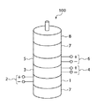
図1は、本発明の第1の実施の形態に係る振動波アクチュエータの構成図である。 FIG. 1 is a configuration diagram of a vibration wave actuator according to a first embodiment of the present invention.
図1において、振動波アクチュエータ100は、圧電体1、3、5と、圧電体1、3、5に設けられた電極2、4、6と、圧電体1、3、5を挟持している弾性体7と、弾性体7に不図示の加圧手段によって加圧接触しているロータ8とを備えている。電極2、4、6に付されている符号は、分極の極性を表している。
In FIG. 1, a
図2は、図1の振動波アクチュエータ100の駆動回路を示す図である。
FIG. 2 is a diagram showing a drive circuit of the
同図において、9はスイッチで、圧電体3に設けられた電極4の極性の異なる電極の一方を圧電体5に設けられた電極6の正極性の電極に切り替えて接続するように構成されている。ここで、図1のロータ8を回転させるためには、弾性体7とロータ8の接触面に回転方向の運動を形成する必要がある。
In the figure,
本実施の形態では、弾性体7に振動を発生させることで、ロータ8に力を伝達する。より具体的には、弾性体7がロータ8と接触する接触面に対して、法線方向の突き上げ振動と、接線方向のねじれ振動を合成した振動を発生させることで、弾性体7とロータ8の接触面に回転方向の運動を形成しており、更に法線方向の振動と接線方向の振動との間の位相をずらすことで効率良くロータ8に力を伝達するように構成されている。
In the present embodiment, force is transmitted to the
以下、図1及び図2を参照しながら、振動波アクチュエータ100の動作を説明する。
Hereinafter, the operation of the
圧電体1に設けられた電極2において、負極性の電極にはグランド電圧が接続されており、正極性の電極には交流電圧V1が印加される。圧電体1は弾性体7に突き上げ振動を形成するように構成された積層圧電素子で、交流電圧V1の周波数を圧電体1,3,5及び弾性体7からなる振動体の共振周波数近傍で且つ共振周波数より高い周波数とすることで、突き上げ振動が上記振動体に形成される。
In the
圧電体3は突き上げ振動の節からずれた部分に設けられた積層圧電素子で、突き上げ振動の振幅に応じた振動検出電圧を電極4の正負の電極間に出力する。また振動検出電圧は交流電圧V1と位相がずれているが、この位相は交流電圧V1の周波数が上記振動体の共振周波数に近づくにつれて、180°から90°の方向へ変化する。この振動検出電圧は圧電体5の電極6の正極性の電極に印加され、上記振動体にねじり振動を発生させる。ここで、スイッチ9は電極4の正負のどちらかの電極をグランド電圧に接続するかによって、電極6へ出力する振動検出電圧の極性を切り替えている。このため、上記振動体に形成される突き上げ振動とねじり振動の位相差の極性がスイッチ9によって切り替えられ、ロータ8の回転方向が切り替わるようになっている。
The
図3は、図2の駆動回路の変形例を示している図である。 FIG. 3 is a diagram showing a modification of the drive circuit of FIG.
図2の駆動回路が、圧電体3の振動検出電圧の極性を切り替えて、当該振動検出圧を圧電体5に印加することでロータ8の回転方向を切り替えているのに対し、図3の駆動回路では、圧電体3の振動検出電圧を圧電体5のどちらの極性の端子に印加するかをスイッチ9で切り替えることでロータ8の回転方向を切り替えている。
The drive circuit of FIG. 2 switches the rotation direction of the
また、図3において、10は抵抗手段で、電極4の正極性の端子を抵抗手段10でグランド電圧に接続することで、圧電体3の振動検出電圧の位相を実際の振動に対してずらすようになっている。これによって、圧電体3の振動検出電圧の位相を調整できるので、突き上げ振動とねじり振動の間の位相差を最適な値に設定することが可能となる。また、ここでは抵抗手段10を圧電体3に並列に接続することで、圧電体3の振動検出電圧の位相を調整をしたが、圧電体3に直列、又は並列に抵抗手段やインダクタ手段を設けても、圧電体3の振動検出電圧の位相を調整することができる。これにより交流電圧V1の駆動周波数を振動体の共振周波数まで利用しない場合や、3相駆動等のように90°以外の位相関係が望まれる用途にも対応できる。
In FIG. 3, 10 is a resistance means, and the positive terminal of the
以上詳細に説明したように、本実施の形態によれば、交流電圧V1を圧電体1に印加して、圧電体1,3,5及び弾性体7からなる振動体に突き上げ振動を形成し、圧電体3はこの突き上げ振動の振幅に応じた振動検出電圧を出力し、圧電体5はこの振動検出電圧を入力して振動体にねじり振動を発生させる。この結果、多相の交流電圧を発生させる駆動回路を必要としないで、単相の駆動電圧で弾性体上に進行性の振動波を形成することができ、駆動回路の構成を簡略化することができる。
As described above in detail, according to the present embodiment, an alternating voltage V1 is applied to the
また、圧電体3から出力される振動検出電圧の位相は、交流電圧V1の周波数が上記振動体の共振周波数に近づくにつれて、交流電圧V1の90°の位相に近づくため、他の振動子や電気的なマッチングによらず位相特性が安定するという効果を奏する。
The phase of the vibration detection voltage output from the
以下、第2の実施の形態について説明する。 Hereinafter, a second embodiment will be described.
図4は、第2の実施の形態に係る振動波アクチュエータの構成を示す図である。 FIG. 4 is a diagram illustrating a configuration of a vibration wave actuator according to the second embodiment.
図4の振動波アクチュエータ200において、上記振動波アクチュエータ100と同一の構成については、同一の番号を付し、その説明を省略する。
In the
図4において、11は圧電体5に設けられた不図示の電極6と弾性体7の間を絶縁するための絶縁体である。
In FIG. 4,
図1の振動波アクチュエータ100は、円柱状の圧電体と弾性体とを積み重ねて構成し、突き上げ振動とねじり振動の異なる2つの振動の合成により、ロータ8を回転させていたが、図4の振動波アクチュエータ200は、リング状の圧電体1,3,5、弾性体7及び絶縁部材11からなる振動体とロータ8とで構成され、リング状の振動体に面外の曲げ振動による進行性の振動波を発生させることでロータ8を回転させる。
The
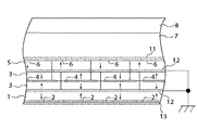
図5は、図4の振動波アクチュエータ200の一部の断面図である。
FIG. 5 is a cross-sectional view of a part of the
図中の矢印は分極の方向を示している。図5において、12は圧電体1と圧電体3及び圧電体3と圧電体5の間に設けられた2枚の電極であり、13は電極2へ給電する給電手段である。圧電体3は電極4を挟む2枚の構成となっている。電極4と電極6の間に挟まれている電極12には、電極4及び電極6と非接続とするための複数のスルーホールが設けられている。
The arrows in the figure indicate the direction of polarization. In FIG. 5,
電極2,4,6は、それぞれ複数の電極ブロックで構成されており、互いに隣り合う電極ブロックの間に、一定の間隔が設けられている。また、互いに隣り合う電極ブロックの極性は反転し、一方の電極ブロックの極性が「+」の場合は、他方の電極ブロックの極性は「−」である。
The
図6は、図4の振動波アクチュエータ200の駆動回路を示す図である。
FIG. 6 is a diagram illustrating a drive circuit of the
電極12はグランド電圧に接続されている。圧電体3の内部に設けられた電極4は、電極12に設けられた複数のスルーホールを介して圧電体5の電極6に接続されている。
The
以下、図5及び図6を参照しつつ、振動波アクチュエータ200の動作を説明する。
Hereinafter, the operation of the
電極2に給電手段13を介して交流電圧V1を印加すると、電極2の互いに隣り合うブロックに対する圧電体1の分極方向が互いに逆方向となる。このため、電極ブロック1つの周方向の幅を半波長とする定在波がリング状の振動体に形成される。電極2,4の電極ブロックは周上に同じパターンで形成され且つ分極方向も隣り合う電極ブロックで交互に極性が反転するように構成されているため、電極4の各電極ブロックには前記定在波に応じた振動検出電圧が出力される。
When the AC voltage V1 is applied to the
次に、振動検出電圧は圧電体5の電極6の電極ブロックに印加される。電極6の電極ブロックは、電極2又は電極4の電極ブロックの位置を基準として、それぞれ上記定在波の4分の1波長ずれた周上の位置に設けられている。
Next, the vibration detection voltage is applied to the electrode block of the
従って、電極6の電極ブロックに振動検出電圧を印加すると上記定在波と位置的にずれた領域に定在波を発生させることになる。
Therefore, when a vibration detection voltage is applied to the electrode block of the
ここで、圧電体3、5はそれぞれひずみに応じた異なる振動検出電圧を出力又は入力するが、電極4と電極6が接続されるため、電極4と電極6には振幅が同一の電圧が生じる。
Here, the
電極4と電極6に生じる電圧は、圧電体3のみで生成される電圧と圧電体5のみで生成される電圧とから算出することができる。例えば、電極4と電極6に生じる電圧は、圧電体3と圧電体5の静電容量が2:1の関係にある場合には、圧電体3の出力電圧の2倍の電圧と圧電体5の出力電圧とを加算して3で割った値となる。
The voltage generated in the
電極4と電極6に生じる電圧が上記リング状の振動体にどのような振動を発生させるのかについて説明する。
A description will be given of how the voltage generated in the
まず、圧電体1の電極2に上記リング状の振動体の共振周波数より高い周波数の交流電圧を印加すると、リング状の振動体に定在波が形成される。定在波は電極2に印加された交流電圧に対して位相が90°以上ずれており、上記リング状の振動体の共振周波数に近づくにつれて位相が90°に近づいていく。
First, when an AC voltage having a frequency higher than the resonance frequency of the ring-shaped vibrating body is applied to the
そうすると、圧電体3は圧電体1と同じ周上の位置に電極4の複数の電極ブロック及び分極パターンが設けられているので、上記定在波に応じた振動検出電圧が電極4に出力される。
Then, since the
圧電体5は、圧電体1の位置を基準として定在波の4分の1波長ずれた周上の位置に電極6の複数の電極ブロック及び分極パターンが設けられているので、電極6の出力電圧は正負の歪みでキャンセルされ、定在波に応じた出力はほとんど0Vとなる。
Since the
従って、電極4と電極6を接続したことによる電極4及び電極6の出力電圧は、電極4単体で出力する振動検出電圧の位相がそのままで、振幅が3分の2になった電圧になる。
Therefore, the output voltage of the
これにより、圧電体1の位置を基準として定在波の4分の1波長ずれた圧電体5に、電極2に印加した交流電圧とは位相のずれた交流電圧を印加することになる。
As a result, an AC voltage having a phase shifted from the AC voltage applied to the
結果として、リング状の振動体に、圧電体1による定在波(以下「第1の定在波」と言う)とは異なる圧電体5による第2の定在波が発生する。
As a result, a second standing wave generated by the
第1の定在波に時間的にずれた位相で振動する第2の定在波が重畳され始めると進行波成分が増加していくようになる。 When the second standing wave that oscillates with a phase shifted in time starts to be superimposed on the first standing wave, the traveling wave component increases.
最初0Vであった電極6単体の出力電圧が第2の定在波に応じた振動検出電圧を出力するようになるので、電極4と電極6に出力される合成された振動検出電圧は第1と第2の定在波による振動検出電圧を合成したものとなる。ただし、上述したように圧電体3の方が圧電体5よりも静電容量が大きいので、電極4の出力の方が支配的になる。
Since the output voltage of the
ここで、圧電体3の積層枚数を増やして圧電体3の静電容量をより大きな値とすると、電極4と電極6を接続した際にこれらの電極に現れる電圧は、ほぼ圧電体3のみで発生する電圧と等しくなる。
Here, when the number of stacked
次に電極2に印加する交流電圧の周波数を上記リング状の振動体の共振周波数とすると、第1の定在波は電極2に印加する交流電圧に対して時間的に90°位相が遅れることになる。また第2の定在波は、電極4及び電極6に出力される交流電圧に対して時間的に90°位相が遅れることになる。ここで、電極4及び電極6に出力される電圧は、上述したように圧電体3の積層枚数を増やして静電容量をより大きな値とした場合には、ほとんど電極4単体の出力電圧となり、電極2に印加する交流電圧に対して時間的に90°遅れた交流電圧となるが、実際には、第2の定在波に応じた振動検出電圧の影響により、90°より位相が遅れた波形を有する電圧となる。それでも、電極2に印加する交流電圧に対してかなり位相がずれた波形の電圧となるので、最終的にある程度の進行波が上記リング状の振動体に形成され、移動体8がこの進行波によって移動することになる。
Next, assuming that the frequency of the AC voltage applied to the
以上詳細に説明したように、本実施の形態によれば、交流電圧V1を圧電体1に印加して、リング状の振動体(圧電体1,3,5及び弾性体7)に第1の定在波を形成し、圧電体3はこの定在波に応じた振動検出電圧を出力し、圧電体5はこの振動検出電圧を入力して振動体に第2の定在波を発生させる。この結果、多相の交流電圧を発生させる駆動回路を必要としないで、単相の駆動電圧で弾性体上に進行性の振動波を形成することができ、駆動回路の構成を簡略化することができる。
As described in detail above, according to the present embodiment, the AC voltage V1 is applied to the
以下、第3の実施の形態について説明する。 The third embodiment will be described below.
上記第2の実施の形態は、電極4と電極6とを接続するのみなので、移動体8の移動方向を切り替えることはできないが、本実施の形態では、圧電体5の分極方向を変えてあり、スイッチ9を付加することで、移動体8の移動方向を切り替えることを可能としたものである。
In the second embodiment, since the
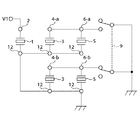
図7は、第3の実施の形態に係る振動波アクチュエータ300の一部の断面図であり、図8は、図7の振動波アクチュエータ300の駆動回路を示す図である。
FIG. 7 is a partial cross-sectional view of the
図7の振動波アクチュエータ300において、上記振動波アクチュエータ200と同一の構成については、同一の番号を付し、その説明を省略する。
In the
振動波アクチュエータ300の構成は、基本的には上記振動波アクチュエータ200の構成と同一であるが、圧電体5の分極方向が異なる。
The configuration of the
圧電体3には電極4−a、4−bが、圧電体5には電極6−a、6−bが設けられている。電極4−aは電極6−aと、電極4−bは電極6−bと接続されている。以下、電極4−a及び電極6−aをグループaといい、電極4−b及び電極6−bをグループbという。
The
図7において、14は弾性体7と電極6−a、6−bとを絶縁すると共にスイッチ9をグループa及びグループbのいずれか一方に接続する配線手段である。
In FIG. 7,
振動波アクチュエータ300では、グランド電圧に接続される電極をグループa及びグループbのいずれか一方にスイッチ9で切り替えることにより移動体8の移動方向を切り替えている。
In the
以下、グランド電圧に接続される電極をグループa及びグループbのいずれか一方に切り替えることで、移動体8の移動方向が切り替わる理由を説明する。
Hereinafter, the reason why the moving direction of the moving
圧電体3は電極4−aと電極4−bとにより互いに異なる方向に分極されており、圧電体5は全て同じ方向に分極されている。また各電極は振動体上に形成される定在波のほぼ2分の1波長の長さで形成されている。そのため、圧電体3が第1の定在波で歪むと、電極4−aと電極4−bの区画で互いに正負の符号が逆の歪みを生ずる。
The
電極4−aと電極4−bの区画の分極方向が互いに逆なので、電極4−a及び電極4−bにはほぼ同一の振動検出電圧が出力される。従って、スイッチ9の接続を考慮しなければ電極6−a及び電極6−bには同一の電圧が印加される。そして、圧電体5は全て同極性に分極してあるので、電極6−a及び電極6−bに同一の交流電圧が印加されると、振動がキャンセルし合うので、ほとんど定在波を発生させることができない。
Since the polarization directions of the sections of the electrode 4-a and the electrode 4-b are opposite to each other, substantially the same vibration detection voltage is output to the electrode 4-a and the electrode 4-b. Accordingly, the same voltage is applied to the electrodes 6-a and 6-b unless the connection of the
しかし、実際には、スイッチ9によってグループa及びグループbのいずれか一方をグランド電圧に接続するので定在波が発生し、スイッチ9を切り替えることで、定在波の位相符号を切り替えることが可能となる。これにより、移動体8の移動方向を切り替えることが可能となる。
However, in actuality, either one of the group a and the group b is connected to the ground voltage by the
本実施の形態によれば、上記第2の実施の形態と同様の効果を奏する。さらに、スイッチ9によりグランド電圧に接続される電極をグループa及びグループbのいずれか一方に切り替えることで、発生する定在波の位相符号が切り替り、移動体8の移動方向を切り替えることができる。よって、単相の駆動電圧で振動波アクチュエータ300を動作させつつ被移動体8の移動方向を切り替えることが可能となる。
According to the present embodiment, the same effects as those of the second embodiment can be obtained. Further, by switching the electrode connected to the ground voltage by the
また、本実施の形態に係る振動波アクチュエータは、第1と第2の定在波の時間的位相差は90°なので、共振状態の際に第1の定在波と第2の定在波の間の位相差が最良の位相差となる。 Further, in the vibration wave actuator according to the present embodiment, since the temporal phase difference between the first and second standing waves is 90 °, the first standing wave and the second standing wave are in resonance. The phase difference between is the best phase difference.
上記第1〜第3の実施の形態では、2つの定在波の一方を振動検出電圧で発生させたが、より多相駆動の場合には2つ以上の定在波を発生するように構成しても良い。 In the first to third embodiments, one of the two standing waves is generated by the vibration detection voltage. However, in the case of multi-phase driving, two or more standing waves are generated. You may do it.
また、第2及び第3の実施の形態でも、第1の実施の形態で説明したような振動検出電圧の位相を調整する位相調整手段を備えるようにしてもよい。これにより、第1と第2の定在波間の位相差を調整することができ、交流電圧V1の駆動周波数を振動体の共振周波数まで利用しない場合や、3相駆動等のように90°以外の位相関係が望まれる用途にも対応できる。 Also in the second and third embodiments, phase adjusting means for adjusting the phase of the vibration detection voltage as described in the first embodiment may be provided. Thereby, the phase difference between the first and second standing waves can be adjusted, and when the drive frequency of the AC voltage V1 is not used up to the resonance frequency of the vibrating body, or other than 90 °, such as three-phase drive It can also be used for applications where a phase relationship is desired.
1,3,5 圧電体
2,4,6,12 電極
7 弾性体
8 移動体
9 スイッチ
11 絶縁体
13 給電手段
14 配線手段
1, 3, 5
Claims (6)
単相の印加電圧が駆動回路から印加されることにより第1定在波を形成する第1電気−機械エネルギー変換手段と、
前記第1定在波の振動に応じて振動検出電圧を出力する第2電気−機械エネルギー変換手段と、
該振動検出電圧が入力されることで第2定在波を形成する第3電気−機械エネルギー変換手段とを有し、
前記振動検出電圧は、前記第1電気−機械エネルギー変換手段と前記第3電気−機械エネルギー変換手段のうち、前記第3電気−機械エネルギー変換手段にのみ印加され、
前記第1定在波と前記第2定在波を合成することで前記進行波を発生することを特徴とする振動波アクチュエータ。 By a progressive wave generated by the displacement standing wave has two positionally phase be excited at different times to the phase on the elastic member, the vibration wave driving the that moving body to pressure contact with the elastic body In the actuator
First electro-mechanical energy conversion means for forming a first standing wave by applying a single-phase applied voltage from a drive circuit ;
Second electro-mechanical energy conversion means for outputting a vibration detection voltage according to the vibration of the first standing wave;
A third electro-mechanical energy conversion means for forming a second standing wave by inputting the vibration detection voltage;
The vibration detection voltage is applied only to the third electro-mechanical energy conversion means among the first electro-mechanical energy conversion means and the third electro-mechanical energy conversion means,
A vibration wave actuator, wherein the traveling wave is generated by synthesizing the first standing wave and the second standing wave.
前記第3電気−機械エネルギー変換手段は、並列に接続された第3及び第4電気−機械エネルギー変換セットを備え、
前記第1電気−機械エネルギー変換セット及び前記第3電気−機械エネルギー変換セットと、前記第2電気−機械エネルギー変換セット及び前記第4電気−機械エネルギー変換セットとのいずれか一方を選択して接地する選択手段を有する請求項1乃至5のいずれか1項記載の振動波アクチュエータ。 The second electro-mechanical energy conversion means includes first and second electro-mechanical energy conversion sets connected in parallel,
The third electro-mechanical energy conversion means includes third and fourth electro-mechanical energy conversion sets connected in parallel,
Select one of the first electro-mechanical energy conversion set, the third electro-mechanical energy conversion set, the second electro-mechanical energy conversion set, and the fourth electro-mechanical energy conversion set, and ground vibration actuator according to any one of claims 1 to 5 having a selecting means for.
Priority Applications (2)
| Application Number | Priority Date | Filing Date | Title |
|---|---|---|---|
| JP2005161799A JP4827441B2 (en) | 2005-06-01 | 2005-06-01 | Vibration wave actuator |
| US11/441,909 US7321182B2 (en) | 2005-06-01 | 2006-05-26 | Oscillatory-wave actuator and method for driving oscillatory-wave actuator |
Applications Claiming Priority (1)
| Application Number | Priority Date | Filing Date | Title |
|---|---|---|---|
| JP2005161799A JP4827441B2 (en) | 2005-06-01 | 2005-06-01 | Vibration wave actuator |
Publications (3)
| Publication Number | Publication Date |
|---|---|
| JP2006340493A JP2006340493A (en) | 2006-12-14 |
| JP2006340493A5 JP2006340493A5 (en) | 2008-07-17 |
| JP4827441B2 true JP4827441B2 (en) | 2011-11-30 |
Family
ID=37493477
Family Applications (1)
| Application Number | Title | Priority Date | Filing Date |
|---|---|---|---|
| JP2005161799A Expired - Fee Related JP4827441B2 (en) | 2005-06-01 | 2005-06-01 | Vibration wave actuator |
Country Status (2)
| Country | Link |
|---|---|
| US (1) | US7321182B2 (en) |
| JP (1) | JP4827441B2 (en) |
Families Citing this family (7)
| Publication number | Priority date | Publication date | Assignee | Title |
|---|---|---|---|---|
| JP5277010B2 (en) * | 2009-02-09 | 2013-08-28 | パナソニック株式会社 | Drive device |
| KR101250798B1 (en) * | 2009-10-27 | 2013-04-04 | 주식회사 로브 | Piezoelectric vibrator capable of amplifying self-vibration and electric/electronic appliance equipped with the same as vibrating means |
| CN103973154B (en) * | 2013-01-28 | 2016-07-06 | 北京大学科技开发部 | A kind of single friction surface microgenerator and manufacture method thereof |
| CN104868777B (en) * | 2014-02-20 | 2019-12-06 | 北京纳米能源与系统研究所 | friction nanometer generator, generator set and power generation method |
| CN104022681B (en) * | 2014-06-25 | 2016-08-17 | 哈尔滨工业大学 | Clipping four-footed indulges curved composite ultrasonic motor oscillator |
| JP2018107437A (en) | 2016-12-27 | 2018-07-05 | キヤノン株式会社 | Vibrator, vibration wave driver, vibration wave motor, and electronic equipment |
| CN106505908B (en) * | 2017-01-05 | 2018-06-12 | 南京工程学院 | It is a kind of can bidirectional rotation single-phase supersonic motor |
Family Cites Families (28)
| Publication number | Priority date | Publication date | Assignee | Title |
|---|---|---|---|---|
| JPS59204477A (en) * | 1983-05-04 | 1984-11-19 | Nippon Kogaku Kk <Nikon> | Surface wave motor utilizing supersonic wave vibration |
| US4727276A (en) * | 1985-03-26 | 1988-02-23 | Canon Kabushiki Kaisha | Driving circuit for vibration wave motor |
| JPH078153B2 (en) * | 1986-07-14 | 1995-01-30 | キヤノン株式会社 | Vibration wave motor device |
| JP2589698B2 (en) * | 1987-07-03 | 1997-03-12 | キヤノン株式会社 | Vibration type actuator device |
| US5134348A (en) * | 1989-04-07 | 1992-07-28 | Canon Kabushiki Kaisha | Vibration wave motor |
| US5191688A (en) * | 1989-07-27 | 1993-03-09 | Olympus Optical Co., Ltd. | Method for producing a superior longitudinal vibrator |
| US5233274A (en) * | 1990-11-30 | 1993-08-03 | Asmo Co., Ltd. | Drive circuit for langevin type ultrasonic bolt-tightening motor |
| US5606390A (en) * | 1991-09-27 | 1997-02-25 | Canon Kabushiki Kaisha | Visual-line detecting device and optical apparatus having the same |
| JP3109870B2 (en) | 1991-09-27 | 2000-11-20 | キヤノン株式会社 | Video camera |
| JPH05284764A (en) | 1992-03-31 | 1993-10-29 | Seiko Instr Inc | Ultrasonic actuator using piezoelectric transformer |
| JPH07170768A (en) * | 1993-12-14 | 1995-07-04 | Nikon Corp | Ultrasonic motor |
| JPH08116685A (en) * | 1994-10-17 | 1996-05-07 | Canon Inc | Vibrating wave motor |
| US6072266A (en) * | 1994-12-21 | 2000-06-06 | Nikon Corporation | Vibration actuator |
| US5665918A (en) * | 1994-12-26 | 1997-09-09 | Canon Kabushiki Kaisha | Linear vibration actuator utilizing combined bending and longitudinal vibration modes |
| JPH0937574A (en) * | 1995-05-12 | 1997-02-07 | Nikon Corp | Oscillatory actuator and control thereof |
| JPH08317672A (en) * | 1995-05-17 | 1996-11-29 | Asmo Co Ltd | Ultrasonic motor apparatus |
| US6084363A (en) * | 1997-01-17 | 2000-07-04 | Minolta Co., Ltd. | Drive pulse generating apparatus for drive device using electromechanical transducer |
| JP2001238473A (en) * | 2000-02-23 | 2001-08-31 | Minolta Co Ltd | Surface acoustic wave motor |
| JP4499877B2 (en) * | 2000-06-13 | 2010-07-07 | セイコーインスツル株式会社 | Ultrasonic motor and electronic device with ultrasonic motor |
| JP2002362250A (en) * | 2001-06-01 | 2002-12-18 | Nippon Pop Rivets & Fasteners Ltd | Molding mounting device and molding clip |
| DE10154526B4 (en) * | 2001-06-12 | 2007-02-08 | Physik Instrumente (Pi) Gmbh & Co | Piezoelectric actuator |
| JP5037767B2 (en) * | 2001-09-19 | 2012-10-03 | キヤノン株式会社 | Control device for vibration actuator |
| FR2832563A1 (en) * | 2001-11-22 | 2003-05-23 | Renault | Control equipment for piezoelectric actuator, comprises direct current convertor and inductor, injector actuators and actuator selector switches connected between mid points of parallel switch pairs |
| JP2003289681A (en) * | 2002-03-27 | 2003-10-10 | Canon Inc | Control device for vibrating type actuator |
| JP4086536B2 (en) * | 2002-04-18 | 2008-05-14 | キヤノン株式会社 | Vibration wave driving device and driving circuit thereof |
| ITTO20020618A1 (en) * | 2002-07-16 | 2004-01-16 | Fiat Ricerche | CONTROL SYSTEM FOR PIEZOELECTRIC ACTUATORS, PARTICULARLY FUEL INJECTORS OF DIESEL ENGINES |
| US7129618B2 (en) * | 2003-03-31 | 2006-10-31 | Canon Kabushiki Kaisha | Control apparatus capable of low-speed driving of vibration type driving apparatus, actuating apparatus using the control apparatus, control method capable of low-speed driving of vibration type driving apparatus, and storage medium storing program including program codes capable of realizing the control method |
| US7119475B2 (en) * | 2003-03-31 | 2006-10-10 | Seiko Epson Corporation | Driving method of piezoelectric actuator, driving apparatus of piezoelectric actuator, electronic watch, electronics, control program of piezoelectric actuator, and storage medium |
-
2005
- 2005-06-01 JP JP2005161799A patent/JP4827441B2/en not_active Expired - Fee Related
-
2006
- 2006-05-26 US US11/441,909 patent/US7321182B2/en not_active Expired - Fee Related
Also Published As
| Publication number | Publication date |
|---|---|
| US7321182B2 (en) | 2008-01-22 |
| JP2006340493A (en) | 2006-12-14 |
| US20060273689A1 (en) | 2006-12-07 |
Similar Documents
| Publication | Publication Date | Title |
|---|---|---|
| JP4827441B2 (en) | Vibration wave actuator | |
| US7382080B2 (en) | Piezoelectric ultrasonic motor driver | |
| JP2008043123A (en) | Ultrasonic motor and vibration detection method of ultrasonic motor | |
| JP5467821B2 (en) | Vibration type actuator | |
| JP2622128B2 (en) | Vibration wave motor device | |
| JP3839898B2 (en) | Drive device for vibration actuator and device using vibration actuator as drive source | |
| JP3126563B2 (en) | Driving device for vibration motor | |
| JP2019517767A (en) | Ultrasonic motor having actuator plate capable of being excited in diagonal direction | |
| JP6577667B2 (en) | Piezoelectric transformer | |
| JP5110750B2 (en) | Drive circuit for vibration actuator | |
| JP4918122B2 (en) | Ultrasonic motor and electronic device with ultrasonic motor | |
| JP4765405B2 (en) | Ultrasonic motor drive device | |
| US20020014812A1 (en) | Actuator using a piezoelectric element | |
| JPS61221584A (en) | Drive circuit of vibration wave motor | |
| JP2000166265A (en) | Vibration-type actuator driving apparatus | |
| JP5586253B2 (en) | Ultrasonic motor | |
| JP2002142475A (en) | Drive circuit of vibration type actuator | |
| WO2003010879A2 (en) | Driving device for ultrasonic motor | |
| JP2002017094A (en) | Ultrasonic motor drive | |
| JP2010004625A (en) | Piezoelectric vibrator and method of driving the same | |
| JP4691752B2 (en) | Drive device for vibration actuator | |
| JP4388273B2 (en) | Ultrasonic motor and electronic device with ultrasonic motor | |
| JP5571521B2 (en) | Ultrasonic motor and driving method thereof | |
| JPH10155289A (en) | Vibration equipment and vibration controller | |
| JP4154404B2 (en) | Vibration type actuator and method for manufacturing vibration type actuator |
Legal Events
| Date | Code | Title | Description |
|---|---|---|---|
| RD05 | Notification of revocation of power of attorney |
Free format text: JAPANESE INTERMEDIATE CODE: A7425 Effective date: 20070626 |
|
| A521 | Request for written amendment filed |
Free format text: JAPANESE INTERMEDIATE CODE: A523 Effective date: 20080530 |
|
| A621 | Written request for application examination |
Free format text: JAPANESE INTERMEDIATE CODE: A621 Effective date: 20080530 |
|
| A977 | Report on retrieval |
Free format text: JAPANESE INTERMEDIATE CODE: A971007 Effective date: 20110223 |
|
| A131 | Notification of reasons for refusal |
Free format text: JAPANESE INTERMEDIATE CODE: A131 Effective date: 20110225 |
|
| A521 | Request for written amendment filed |
Free format text: JAPANESE INTERMEDIATE CODE: A523 Effective date: 20110422 |
|
| TRDD | Decision of grant or rejection written | ||
| A01 | Written decision to grant a patent or to grant a registration (utility model) |
Free format text: JAPANESE INTERMEDIATE CODE: A01 Effective date: 20110906 |
|
| A01 | Written decision to grant a patent or to grant a registration (utility model) |
Free format text: JAPANESE INTERMEDIATE CODE: A01 |
|
| A61 | First payment of annual fees (during grant procedure) |
Free format text: JAPANESE INTERMEDIATE CODE: A61 Effective date: 20110913 |
|
| FPAY | Renewal fee payment (event date is renewal date of database) |
Free format text: PAYMENT UNTIL: 20140922 Year of fee payment: 3 |
|
| FPAY | Renewal fee payment (event date is renewal date of database) |
Free format text: PAYMENT UNTIL: 20140922 Year of fee payment: 3 |
|
| LAPS | Cancellation because of no payment of annual fees |