EP1267193A1 - Präzisionsgehalterter Kippspiegel für optische Geräte - Google Patents
Präzisionsgehalterter Kippspiegel für optische Geräte Download PDFInfo
- Publication number
- EP1267193A1 EP1267193A1 EP20020013140 EP02013140A EP1267193A1 EP 1267193 A1 EP1267193 A1 EP 1267193A1 EP 20020013140 EP20020013140 EP 20020013140 EP 02013140 A EP02013140 A EP 02013140A EP 1267193 A1 EP1267193 A1 EP 1267193A1
- Authority
- EP
- European Patent Office
- Prior art keywords
- tilting mirror
- tilting
- precision
- mirror
- cylindrical part
- Prior art date
- Legal status (The legal status is an assumption and is not a legal conclusion. Google has not performed a legal analysis and makes no representation as to the accuracy of the status listed.)
- Granted
Links
- 230000003287 optical effect Effects 0.000 title claims abstract description 11
- 239000000463 material Substances 0.000 claims description 3
- 239000011521 glass Substances 0.000 claims description 2
- 239000006112 glass ceramic composition Substances 0.000 claims description 2
- 238000003466 welding Methods 0.000 claims description 2
- 239000000853 adhesive Substances 0.000 claims 1
- 230000001070 adhesive effect Effects 0.000 claims 1
- 239000000919 ceramic Substances 0.000 claims 1
- 238000005096 rolling process Methods 0.000 description 9
- 238000004519 manufacturing process Methods 0.000 description 4
- 238000010276 construction Methods 0.000 description 2
- 238000004026 adhesive bonding Methods 0.000 description 1
- 230000005540 biological transmission Effects 0.000 description 1
- 229910010293 ceramic material Inorganic materials 0.000 description 1
- 238000005520 cutting process Methods 0.000 description 1
- 230000001419 dependent effect Effects 0.000 description 1
- 238000006073 displacement reaction Methods 0.000 description 1
- 239000002241 glass-ceramic Substances 0.000 description 1
- 238000003384 imaging method Methods 0.000 description 1
- 238000009434 installation Methods 0.000 description 1
- 238000003754 machining Methods 0.000 description 1
- 230000000149 penetrating effect Effects 0.000 description 1
- 230000005855 radiation Effects 0.000 description 1
- 238000003860 storage Methods 0.000 description 1
Images


Classifications
-
- G—PHYSICS
- G02—OPTICS
- G02B—OPTICAL ELEMENTS, SYSTEMS OR APPARATUS
- G02B7/00—Mountings, adjusting means, or light-tight connections, for optical elements
- G02B7/18—Mountings, adjusting means, or light-tight connections, for optical elements for prisms; for mirrors
- G02B7/182—Mountings, adjusting means, or light-tight connections, for optical elements for prisms; for mirrors for mirrors
- G02B7/1821—Mountings, adjusting means, or light-tight connections, for optical elements for prisms; for mirrors for mirrors for rotating or oscillating mirrors
-
- G—PHYSICS
- G02—OPTICS
- G02B—OPTICAL ELEMENTS, SYSTEMS OR APPARATUS
- G02B26/00—Optical devices or arrangements for the control of light using movable or deformable optical elements
- G02B26/08—Optical devices or arrangements for the control of light using movable or deformable optical elements for controlling the direction of light
- G02B26/0816—Optical devices or arrangements for the control of light using movable or deformable optical elements for controlling the direction of light by means of one or more reflecting elements
Definitions
- the invention relates to a tilting mirror for optional switching on and off into an optical beam path of an optical device.
- a mirror is tilted to one Beams in different ways through a multifunctional to steer optical device.
- the radiation emanating from the object is optionally available to the eye of the observer or a documentation medium.
- Such Arrangements require high angular accuracy and reproducibility the mirror position in the active position.
- DE-PS 2 029 850 is a photometer for microscopes known, in which - compare FIG. 1 there - a lifting magnet which or swung out into or out of the beam path.
- DE-OS 2 717 033 is also a microphotographic Light measuring device known, in which - compare Figure 2 there - a Deflecting mirror introduced into an optical beam path can be that this deflecting mirror by means of a manually operated Carrier is pushed into the active position.
- the tilting mirror on its mirror side in at least one recess, for example a groove, in its end region having.
- the carrier has Bracket for the tilt mirror Support parts for tilting the tilt mirror such that two carrier parts are attached to the carrier, on their respective End areas a continuous cylindrical stop and rolling body is firmly arranged. It is also possible that the carrier parts are angular are trained and are articulated arm-like on the carrier. It can be useful that on each support part instead of a continuous Body a cylindrical stop and rolling body is fixedly arranged and that the precision surfaces in their respective to the tilt axis or Body-pointing areas are rounded.
- the carrier has an opening for the Passage of rays having the optical axes, wherein the size of the opening with the area size of the reflection area of the Tilt mirror corresponds.
- the operation of the tilt function the tilting mirror with motorized means that are in the interior of the cylindrical part are arranged. After all, it is also possible that in the area of its cylindrical part a lever for operating the Tilt function of the tilt mirror is articulated.
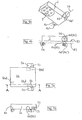
- a tilting mirror 1 is shown, the one on its underside has specular reflection area 2.
- a cylindrical part 4 Located at its end area a cylindrical part 4, the axis of which with the tilt axis 14 of the Tilting mirror 1 coincides. It can be seen that the cylindrical part 4 is "extended" to both sides of the tilt mirror 1, so to speak Projections 4a and 4b are formed.
- Actuatable lever 3 can this tilting mirror about its axis 14 be pivoted or tilted.
- This tilting mirror arrangement corresponds to that shown in FIG. 1b
- Carrier 5 which is designed as a plate, which has an opening 8 for the incident or reflected or transmitted beam path.
- the patches 6b and 6c precision contact surfaces for the projections 4a and 4b of the represent cylindrical part 4.
- the construction of such is carried out that the surfaces 6a and 6b and 6c together a "3-surface support" Realize 6a - 6c for the tilting mirror 1. So that Tilting mirror is protected against unwanted lateral displacement contact surfaces 7a - 7d in an angled arrangement to the precision contact surfaces 6b and 6c.
- FIG 2 is an exploded view of the active position of the Tilting mirror 1 shown. It can be seen that the reflection area 2 having the underside of the tilting mirror 1 lies on a fictitious level E1, the cylindrical part 4 or its projections 4a and 4b also lies on level E1. Mathematically speaking, this means that the trace the fictitious plane E1 the circular cross section of the cylindrical Part 4 touches tangentially. This constellation is with one Manufacturing process can be implemented in a precise manner. There is a possibility in that the cylindrical part 4 and the tilting mirror 1 - on one lying together - firmly connected to each other. This can be done for example by means of gluing, kittens or welding.
- the tilting mirror 1 is connected to its support 5 in Shown out of action, so that the beam path 13 through the opening 8 can step freely.
- the tilting mirror 1 is in the operative position, so that the Incident beam path 9 is reflected at the reflection region 2 and as Reflection beam path 10 is deflected. It is shown purely schematically that acts on the lever 3, a force vector 11, the precise tilt of the Tilting mirror 1 causes. In a way, the force presses against the three Patches 6a - 6c. To switch off the tilting mirror 1 acts in place this force 11 a counterforce 12, compare the corresponding Force vector 12, the direction of action well outside of supporting triangle - formed by the surfaces 6a to 6c - lies.
- FIG 4a is a small variation of the tilting mirror 1 or - more precisely - Only the projections of the cylindrical part 4 - shown. you recognizes that the cylindrical lugs 4c and 4d flattened areas 4c 'and 4d'. These flattened areas are co-planar together with the underside of the tilting mirror 4 in the plane E1. This will illustrated in Figure 4b.
- This design tilting mirror variant has the manufacturing advantage that the level E1 by a single cutting precision manufacturing process can be realized. It is still emphasized that the flattened areas 4c 'and 4d' only represent narrow "webs" around the translational or tilting or Rolling process not to be affected atypical of movement.
- FIGS. 5a and 5b 1a and the corresponding carrier Recognized in Figure 5a top view of the tilting mirror 1a, while the one below it actual main part of the carrier is not recognizable. For that are on both sides Carrier parts 5a hinged to the actual carrier. You can see that it are angled arm-shaped support parts 5a, which on or on their respective end regions a cylindrical stop and rolling body Wear 5b. It can be a continuous cylinder body act. However, it is also possible that instead of a one-piece cylindrical body 5b two cylindrical partial bodies are provided.
- FIG. 5b shows a side view along the section AA of FIG. 5b It can be seen that the tilting mirror 1 a in its end region Has recess 15, for example, as a continuous groove can be designed. This groove takes the or the stop and Rolling body 5b.
- Figure 5b shows that the tilting mirror 1a in the active position is positioned so that the top of the recess 15 the body (s) 5b not contacted. This ensures that the tilting mirror 1a only lies or lies precisely on a 3-surface support 6a - 6c.
- the Function of the cylindrical body 5b is therefore only in the Bring the tilting mirror 1a out of active position as a stop and Roll body to serve.
- the cross-sectional shape of the recess 15 can be one Have a large number of variants, as described in the subclaims.
- the precision contact surfaces 6b and 6c are in this variant of the tilting mirror 1a designed in such a way that it can be used in its stop and Rolling body 5b facing part are rounded. So the combined Translational, tilting and rolling process of the tilting mirror 1a improved.
- the tilting mirror 1a instead of a continuous one Recess only has two blind holes in its rear area, in the corresponding pins - i.e. cylindrical parts - of the carrier 5 intervention.
- the advantages of the present invention are that for the high Positioning accuracy and reproducibility only one by three precision-machined planes formed level (E1 ⁇ E2) is required and no subsequent adjustment of the functional position is necessary. A special one designed mechanical tilt axis and a precise storage of such Axis are not necessary. The mechanics - the stop geometries - to limit any lateral movements of the Tilting mirrors have no special design requirements.
Landscapes
- Physics & Mathematics (AREA)
- General Physics & Mathematics (AREA)
- Optics & Photonics (AREA)
- Mounting And Adjusting Of Optical Elements (AREA)
- Mechanical Light Control Or Optical Switches (AREA)
- Optical Elements Other Than Lenses (AREA)
Abstract
Description
- Figur 1a:
- eine erste Ausführungsform eines erfindungsgemäßen Kippspiegels;
- Figur 1b:
- den zu dem in Figur 1a gezeigten Kippspiegel gehörenden Träger;
- Figur 2:
- eine Seitenansicht - in "gesprengter" Darstellung - des Kippspiegels in Wirkstellung;
- Figur 3a:
- den Kippspiegel mit zugeordnetem Träger (außer Wirkstellung);
- Figur 3b:
- den an bzw. auf dem Träger präzise anliegenden Kippspiegel (in Wirkstellung);
- Figur 4a:
- eine leicht abgewandelte Ausführungsform eines Kippspiegels;
- Figur 4b:
- eine Seitenansicht - in "gesprengter" Darstellung - dieser abgewandelten Ausführungsform mit einem lediglich angedeuteten Trägerteil;
- Figur 5a:
- eine Draufsicht auf eine weitere Ausführungsform eines Kippspiegels mit darunter befindlichem Träger, wobei in dieser Darstellung lediglich einige Trägerteile erkennbar sind;
- Figur 5b:
- die Seitenansicht des in Fig. 5a dargestellten Kippspiegels mit präzise anliegendem Trägerteil in 3-Flächen-Auflage, wobei in dieser rein schematischen Darstellung lediglich zwei Flächen erkennbar sind.
- 1, 1a
- - Kippspiegel
- 2
- - Reflexionsbereich von (1) bzw. (1a)
- 3
- - Hebel
- 4
- - zylinderförmiger Teil von (1)
- 4a, 4b
- - Vorsprünge von (4)
- 4c, 4d
- - zylinderförmige Ansätze an (1)
- 4c', 4d'
- - Abflachungsbereich(e) von (4c) bzw. (4d)
- 5
- - Träger für (1)
- 5a, 5b
- - Trägerteil(e) für (1a)
- 5a
- - abgewinkelte(r), armförmige(r) Trägerteil(e) für (5b)
- 5b
- - zylinderförmiger Anschlag- und Abrollkörper für (1 a)
- 6a - 6c
- - Präzisions-Flächenstück(e)
- 6a
- - Präzisions-Anschlagfläche
- 6b, 6c
- - Präzisions-Auflagefläche(n)
- 7a - 7d
- - Anlagefläche(n)
- 8
- - Öffnung für Strahlengang (9) bzw. (13)
- 9
- - Einfalls-Strahlengang
- 10
- - Reflexions-Strahlengang
- 11
- - Kraftvektor (in - Wirkstellung - bringen)
- 12
- - Kraftvektor (außer - Wirkstellung - bringen)
- 13
- - durchtretender Strahlengang
- 14
- - Kippachse
- 15
- - Ausnehmung in (1a) zur präzisen Ausführung der Kippbewegung von (1a)
- E1
- - gemeinsame Ebene von (2) und (4) bzw. (4c', 4d')
- E2
- - gemeinsame Ebene von (6a), (6b) und (6c)
Claims (10)
- Kippspiegel mit Halterung zum wahlweisen Umlenken bzw. Durchlassen eines Strahlenbündels in einem optischen Gerät, vorzugsweise einem Mikroskop, dadurch gekennzeichnet, dass der Kippspiegel (1, 1a) auf einem Träger (5) angeordnet ist, der eine 3-Flächen-Auflage (6a-6c) für die Präzisionshalterung des Kippspiegels (1, 1a) in Wirkstellung aufweist.
- Kippspiegel nach Anspruch 1, dadurch gekennzeichnet, dass er auf einer Seite einen als Spiegelfläche ausgebildeten Reflexionsbereich (2) aufweist und sein Endbereich als ein eine Kippachse (14) aufweisender zylinderförmiger Teil (4) ausgebildet ist.
- Kippspiegel nach Anspruch 2, dadurch gekennzeichnet, dass der zylinderförmige Teil (4) Vorsprünge (4a, 4b) entlang der Kippachse (14) aufweist.
- Kippspiegel nach mindestens einem der vorhergehenden Ansprüche, dadurch gekennzeichnet, dass der Träger (5) zur Halterung des Kippspiegels (1, 1a) Präzisionsflächen (6b, 6c) zur Aufnahme des zylinderförmigen Teils (4, 4a, 4b) sowie eine Präzisionsfläche (6a) zum Anschlag des Kippspiegels (1, 1a) in Wirkstellung aufweist.
- Kippspiegel nach mindestens einem der vorhergehenden Ansprüche, dadurch gekennzeichnet, dass der Träger (5) zusätzliche Anlageflächen (7a, 7b; 7c, 7d) für die Vorsprünge (4a, 4b) aufweist und dass diese im wesentlichen senkrecht auf den Präzisions-Auflageflächen (6b, 6c) stehen.
- Kippspiegel nach mindestens einem der vorhergehenden Ansprüche, dadurch gekennzeichnet, dass der Kippspiegel (1) mit seinem zylinderförmigen Teil (4; 4a, 4b, 4c, 4d) und der Träger (5) zusammen mit seinen die Flächen (6a - 6c, 7a - 7d) aufweisenden säulen- bzw. "U"-förmigen Verkörperungen einstückig ausgebildet ist.
- Kippspiegel nach mindestens einem der vorhergehenden Ansprüche, dadurch gekennzeichnet, dass einerseits die den Reflexionsbereich (2) aufweisende Seite des Kippspiegels (1, 1a) und der zylinderförmige Teil (4) auf einer gemeinsamen Ebene (E1) liegen und andererseits die Präzisions-Flächenstücke (6a - 6c) des Trägers (5) ebenfalls auf einer gemeinsamen Ebene (E2) liegen, wobei beide Ebenen (E1, E2) in Wirkstellung des Kippspiegels (1) zusammenfallen (E1 ≡ E2).
- Kippspiegel nach mindestens einem der vorhergehenden Ansprüche, dadurch gekennzeichnet, dass der zylinderförmige Teil (4) und der Kippspiegel (1) einerseits, sowie die die Flächen (6a-6c, 7a-7d) aufweisenden Verkörperungen andererseits mit dem Träger (5) mittels Klebens, Kittens oder Schweißens präzisionsorientiert verbunden sind.
- Kippspiegel nach mindestens einem der vorhergehenden Ansprüche, dadurch gekennzeichnet, dass der Kippspiegel (1) mit seinem zylinderförmigen Teil (4) einerseits, sowie der Träger (5) mit seinem die Flächen (6a - 6c, 7a - 7d) aufweisenden Verkörperungen andererseits aus ein und demselben Material gefertigt sind, wobei das Material ein Glas-, ein Keramik- bzw. ein Glaskeramik-Material ist.
- Kippspiegel nach mindestens einem der vorhergehenden Ansprüche, dadurch gekennzeichnet, dass an Stelle der planen Präzisions-Anschlagfläche (6a) eine einen Anschlag-Punkt realisierende nicht-plane Fläche vorgesehen ist.
Applications Claiming Priority (2)
| Application Number | Priority Date | Filing Date | Title |
|---|---|---|---|
| DE10128965 | 2001-06-15 | ||
| DE10128965A DE10128965A1 (de) | 2001-06-15 | 2001-06-15 | Präzisionsgehalterter Kippspiegel für optische Geräte |
Publications (2)
| Publication Number | Publication Date |
|---|---|
| EP1267193A1 true EP1267193A1 (de) | 2002-12-18 |
| EP1267193B1 EP1267193B1 (de) | 2005-01-19 |
Family
ID=7688335
Family Applications (1)
| Application Number | Title | Priority Date | Filing Date |
|---|---|---|---|
| EP02013140A Expired - Lifetime EP1267193B1 (de) | 2001-06-15 | 2002-06-14 | Präzisionsgehalterter Kippspiegel für optische Geräte |
Country Status (4)
| Country | Link |
|---|---|
| US (1) | US6890082B2 (de) |
| EP (1) | EP1267193B1 (de) |
| JP (1) | JP4104920B2 (de) |
| DE (2) | DE10128965A1 (de) |
Families Citing this family (3)
| Publication number | Priority date | Publication date | Assignee | Title |
|---|---|---|---|---|
| JP4856631B2 (ja) * | 2004-05-29 | 2012-01-18 | ポラティス リミテッド | 光学的スイッチ |
| US7666859B2 (en) * | 2006-09-08 | 2010-02-23 | Norman Turkowitz | Skin compositions containing hydrocortisone |
| CN115016085B (zh) * | 2021-02-19 | 2026-01-27 | 台湾东电化股份有限公司 | 光学元件驱动机构 |
Citations (5)
| Publication number | Priority date | Publication date | Assignee | Title |
|---|---|---|---|---|
| DE2341038A1 (de) * | 1972-08-24 | 1974-02-28 | Wild Heerbrugg Ag | Makro-mikroskop |
| US4930883A (en) * | 1987-07-06 | 1990-06-05 | Salzman Ronald H | Photovisual star diagonal |
| US5121220A (en) * | 1991-02-20 | 1992-06-09 | Jason Empire, Inc. | Ocular turret telescope system |
| US5394270A (en) * | 1992-10-19 | 1995-02-28 | Thyssen Stahl Aktiengesellschaft | Optical beam divider for a laser beam |
| US5793528A (en) * | 1996-10-31 | 1998-08-11 | Litton Systems, Inc. | Channel selector for multiple channel sight |
Family Cites Families (3)
| Publication number | Priority date | Publication date | Assignee | Title |
|---|---|---|---|---|
| DE2029850B2 (de) | 1970-06-18 | 1971-09-23 | Ernst Leitz Gmbh, 6330 Wetzlar | Fotometer fuer mikroskope |
| DE2717033C2 (de) | 1977-04-18 | 1986-01-30 | Ernst Leitz Wetzlar Gmbh, 6330 Wetzlar | Mikrofotografische Lichtmeßeinrichtung |
| JPH03505987A (ja) * | 1989-05-11 | 1991-12-26 | ハーグ ― シュトライト アクチェンゲゼルシャフト | 顕微鏡の撮影装置及びダイアフラム構造体 |
-
2001
- 2001-06-15 DE DE10128965A patent/DE10128965A1/de not_active Withdrawn
-
2002
- 2002-06-14 US US10/171,387 patent/US6890082B2/en not_active Expired - Lifetime
- 2002-06-14 JP JP2002174218A patent/JP4104920B2/ja not_active Expired - Fee Related
- 2002-06-14 DE DE50202029T patent/DE50202029D1/de not_active Expired - Lifetime
- 2002-06-14 EP EP02013140A patent/EP1267193B1/de not_active Expired - Lifetime
Patent Citations (5)
| Publication number | Priority date | Publication date | Assignee | Title |
|---|---|---|---|---|
| DE2341038A1 (de) * | 1972-08-24 | 1974-02-28 | Wild Heerbrugg Ag | Makro-mikroskop |
| US4930883A (en) * | 1987-07-06 | 1990-06-05 | Salzman Ronald H | Photovisual star diagonal |
| US5121220A (en) * | 1991-02-20 | 1992-06-09 | Jason Empire, Inc. | Ocular turret telescope system |
| US5394270A (en) * | 1992-10-19 | 1995-02-28 | Thyssen Stahl Aktiengesellschaft | Optical beam divider for a laser beam |
| US5793528A (en) * | 1996-10-31 | 1998-08-11 | Litton Systems, Inc. | Channel selector for multiple channel sight |
Also Published As
| Publication number | Publication date |
|---|---|
| JP2003066349A (ja) | 2003-03-05 |
| JP4104920B2 (ja) | 2008-06-18 |
| DE50202029D1 (de) | 2005-02-24 |
| EP1267193B1 (de) | 2005-01-19 |
| US20030011862A1 (en) | 2003-01-16 |
| US6890082B2 (en) | 2005-05-10 |
| DE10128965A1 (de) | 2003-01-09 |
Similar Documents
| Publication | Publication Date | Title |
|---|---|---|
| DE3881763T2 (de) | Handbetriebene Steuervorrichtung. | |
| DE102011003603B4 (de) | Durchlichtbeleuchtungseinrichtung für ein Mikroskop | |
| DE102009025309B4 (de) | Kinematischer Halter | |
| DE19728035B4 (de) | Beobachtungsvorrichtung mit Schrägbeleuchtung | |
| EP0041107A1 (de) | Binokulares Ophthalmoskop | |
| EP1207392B1 (de) | Vorrichtung zum Aufnehmen von Mikrodissektaten | |
| DE102007030579B4 (de) | Lateral verstellbare Fassung für optische Elemente | |
| DE60217128T2 (de) | Veränderliche Anordnung mikroskopischer Löcher | |
| EP0920651B1 (de) | Feinfokussiertisch | |
| WO2005045501A1 (de) | Invertierbares lichtmikroskop | |
| DE102008011527A1 (de) | Beleuchtungseinrichtung für ein Mikroskop | |
| DE10119369A1 (de) | Beobachtungsvorrichtung | |
| EP1267193B1 (de) | Präzisionsgehalterter Kippspiegel für optische Geräte | |
| DE602004004926T2 (de) | Zur erzeugung eines bildes von fingerabdrücken geeignete optische abbildungseinrichtung | |
| DE10340604B3 (de) | Verfahren und Vorrichtung zum lösbaren Befestigen sowie zum Verändern der Relativposition zweier Bauteile zueinander | |
| DE10004661B4 (de) | Vorrichtung zum Schwenken eines Lichtstrahls | |
| DE2112755A1 (de) | Optischer Sender oder Verstaerker | |
| DE112023000310T5 (de) | Modenmischer | |
| DE2144588A1 (de) | Beleuchtung fuer kontroll- oder bedienungselemente von fahrzeugen | |
| DE102007028402B4 (de) | Mikroskop und Klemmschutzvorrichtung für ein Mikroskop | |
| DE10143357B4 (de) | Starrer Lichtleiter | |
| EP0802437A1 (de) | Drehspiegelanordnung zur Fokussierung eines einfallenden Lichtstrahls und/oder zur Änderung der Fokuslage eines bereits fokussierten Lichtstrahls, insbesondere Laserstrahls | |
| DE69902502T2 (de) | Optisches Stellglied zur Führung eines einfallenden Lichtstrahls auf eine sich ausserhalb des Stellglieds befindliche, feststehende Oberfläche | |
| EP1162489B1 (de) | Fokussiertrieb für optische Instrumente | |
| DE102004048296B4 (de) | Vorrichtung zum Umschalten der Betriebsarten eines Mikroskoptubus |
Legal Events
| Date | Code | Title | Description |
|---|---|---|---|
| PUAI | Public reference made under article 153(3) epc to a published international application that has entered the european phase |
Free format text: ORIGINAL CODE: 0009012 |
|
| AK | Designated contracting states |
Kind code of ref document: A1 Designated state(s): AT BE CH CY DE DK ES FI FR GB GR IE IT LI LU MC NL PT SE TR |
|
| AX | Request for extension of the european patent |
Free format text: AL;LT;LV;MK;RO;SI |
|
| 17P | Request for examination filed |
Effective date: 20030530 |
|
| 17Q | First examination report despatched |
Effective date: 20030703 |
|
| AKX | Designation fees paid |
Designated state(s): CH DE FR GB LI |
|
| RAP1 | Party data changed (applicant data changed or rights of an application transferred) |
Owner name: LEICA MICROSYSTEMS (SCHWEIZ) AG |
|
| GRAP | Despatch of communication of intention to grant a patent |
Free format text: ORIGINAL CODE: EPIDOSNIGR1 |
|
| GRAS | Grant fee paid |
Free format text: ORIGINAL CODE: EPIDOSNIGR3 |
|
| GRAA | (expected) grant |
Free format text: ORIGINAL CODE: 0009210 |
|
| AK | Designated contracting states |
Kind code of ref document: B1 Designated state(s): CH DE FR GB LI |
|
| REG | Reference to a national code |
Ref country code: GB Ref legal event code: FG4D Free format text: NOT ENGLISH |
|
| REG | Reference to a national code |
Ref country code: CH Ref legal event code: EP |
|
| REG | Reference to a national code |
Ref country code: IE Ref legal event code: FG4D Free format text: GERMAN |
|
| REF | Corresponds to: |
Ref document number: 50202029 Country of ref document: DE Date of ref document: 20050224 Kind code of ref document: P |
|
| GBT | Gb: translation of ep patent filed (gb section 77(6)(a)/1977) |
Effective date: 20050323 |
|
| PLBE | No opposition filed within time limit |
Free format text: ORIGINAL CODE: 0009261 |
|
| STAA | Information on the status of an ep patent application or granted ep patent |
Free format text: STATUS: NO OPPOSITION FILED WITHIN TIME LIMIT |
|
| ET | Fr: translation filed | ||
| 26N | No opposition filed |
Effective date: 20051020 |
|
| PGFP | Annual fee paid to national office [announced via postgrant information from national office to epo] |
Ref country code: FR Payment date: 20090615 Year of fee payment: 8 |
|
| PGFP | Annual fee paid to national office [announced via postgrant information from national office to epo] |
Ref country code: GB Payment date: 20090618 Year of fee payment: 8 |
|
| REG | Reference to a national code |
Ref country code: CH Ref legal event code: PUE Owner name: EICA INSTRUMENTS (SINGAPORE) PTE. LTD. Free format text: LEICA MICROSYSTEMS (SCHWEIZ) AG#MAX SCHMIDHEINY-STRASSE 201#9435 HEERBRUGG (CH) -TRANSFER TO- LEICA INSTRUMENTS (SINGAPORE) PTE. LTD.#12 TEBAN GARDENS CRESCENT#608924 SINGAPORE (SG) |
|
| GBPC | Gb: european patent ceased through non-payment of renewal fee |
Effective date: 20100614 |
|
| REG | Reference to a national code |
Ref country code: FR Ref legal event code: ST Effective date: 20110228 |
|
| PG25 | Lapsed in a contracting state [announced via postgrant information from national office to epo] |
Ref country code: FR Free format text: LAPSE BECAUSE OF NON-PAYMENT OF DUE FEES Effective date: 20100630 |
|
| PG25 | Lapsed in a contracting state [announced via postgrant information from national office to epo] |
Ref country code: GB Free format text: LAPSE BECAUSE OF NON-PAYMENT OF DUE FEES Effective date: 20100614 |
|
| PGFP | Annual fee paid to national office [announced via postgrant information from national office to epo] |
Ref country code: CH Payment date: 20210622 Year of fee payment: 20 |
|
| PGFP | Annual fee paid to national office [announced via postgrant information from national office to epo] |
Ref country code: DE Payment date: 20210827 Year of fee payment: 20 |
|
| REG | Reference to a national code |
Ref country code: DE Ref legal event code: R071 Ref document number: 50202029 Country of ref document: DE |
|
| REG | Reference to a national code |
Ref country code: CH Ref legal event code: PL |