EP1267163A2 - Prüfgerät zur fotoelektrischen Prüfung des Leimungsgrades und der Saugfähigkeit - Google Patents
Prüfgerät zur fotoelektrischen Prüfung des Leimungsgrades und der Saugfähigkeit Download PDFInfo
- Publication number
- EP1267163A2 EP1267163A2 EP02012966A EP02012966A EP1267163A2 EP 1267163 A2 EP1267163 A2 EP 1267163A2 EP 02012966 A EP02012966 A EP 02012966A EP 02012966 A EP02012966 A EP 02012966A EP 1267163 A2 EP1267163 A2 EP 1267163A2
- Authority
- EP
- European Patent Office
- Prior art keywords
- sample
- meniscus
- test
- test device
- cylinder
- Prior art date
- Legal status (The legal status is an assumption and is not a legal conclusion. Google has not performed a legal analysis and makes no representation as to the accuracy of the status listed.)
- Granted
Links
Images
Classifications
-
- G—PHYSICS
- G01—MEASURING; TESTING
- G01N—INVESTIGATING OR ANALYSING MATERIALS BY DETERMINING THEIR CHEMICAL OR PHYSICAL PROPERTIES
- G01N33/00—Investigating or analysing materials by specific methods not covered by groups G01N1/00 - G01N31/00
- G01N33/34—Paper
- G01N33/346—Paper sheets
Definitions
- the invention relates to a test device for photoelectric testing of the degree of sizing and Absorbance of samples from paper, cardboard, filter material or another absorbent Material using a test liquid and using a horizontal in one Test plane arranged sample, which is held in place with an elastic pressure ring.
- the electric light source with a lamp is located above the platen In relation to the small amount of test liquid, this should not be neglected Has power consumption and heat development.
- the heat generated leads to a Temperature increase of the test liquid in the scoop, even after the measurement is finished and not complete after shutting down and scooping new test liquid is balanced. In the case of continuous measurements, this heating of the test liquid leads to shorter times Breakthrough times of the test liquid, which falsify the measurement result.
- a light source called a cold light lamp, which is equipped with a halogen lamp.
- the light is transported with a Glass fiber strand as light guide.
- the disadvantage is the high level of design complexity and the bundling of light that must be distributed evenly over the material sample.
- the object of the present invention is to create a comparatively simple one Tester for photoelectric testing of the degree of sizing and absorbency of paper with the help of a test liquid
- a test device is to be provided that is easy to use handle as well as inexpensively with as little mechanical effort as possible is to be produced.
- the test results obtained should be reproducible.
- the object is achieved by a testing device for photoelectric testing the degree of sizing and the absorbency of paper, cardboard, filter material or another absorbent material a stationary, via an inlet line with a microdosing pump connected meniscus cylinder for the test liquid, with the commissioning of the Microdosing pump of the meniscus cylinder with an overflowing test liquid existing meniscus and the sample is arranged floating on the meniscus.
- test liquid cannot heat up when using a heat-emitting light source. If a meniscus is created on the meniscus cylinder using a microdosing pump, the test liquid can be exchanged constantly and by renewing against heating to be protected. At the same time, the movement of the test liquid causes the formation of Air bubbles under the sample and falsification of the measurement results are excluded.
- the meniscus cylinder is in an overflow cylinder for Test liquid arranged, the overflow cylinder leading to the microdosing pump Return line has.
- the arrangement of a microdosing pump continues to provide the Possibility of a storage tank in the return line, optionally with a filter device to be arranged so that the test liquid is to be kept free of contamination by the Get paper samples into the test liquid during operation.
- an electrical light source is provided, which is formed by an electroluminescent filament formed in foil form.
- Electroluminescent lamps are known per se. They are constructed in foil form, which a front electrode made of transparent material, a fluorescent layer, an insulation layer and has a back electrode. The front electrode and the back electrode are included connected to a connection. A voltage is applied to the connection conductors. Thereby the embedded phosphor emits light that exits through the transparent front electrode.
- the electrical energy is converted directly into light, without generating disruptive heat, that can falsify the measurement result. This means that reproducible measurement results are also possible in the Continuous operation of the test device generated.
- the filament is preferably curved in a parabolic or elliptical shape can be so that a completely diffuse homogeneous measurement light is generated on the sample can.
- the evaluation of the measurement results can be done with one above the sample at the apex made of the electroluminescent luminous element be a photoelectric sensor and / or an optoelectronic Detection device, possibly with an optical system, such as a CCD video camera, includes.
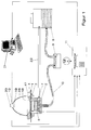
- FIG. 1 shows a sample 1 to be tested made of paper, cardboard, filter material or another shown absorbent material.
- the sample 1 is placed on an overflow cylinder 2 with sample support 3 and through a for example, made of foam rubber held sample holder ring 4.
- a for example, made of foam rubber held sample holder ring 4 During the measurement is, by the constant renewal of the meniscus 5 shown in Figure 2 in Meniscus cylinder 6 flowing test liquid 7 caught in the overflow cylinder 2 and in returned a reservoir 8.
- Test liquid 7 removed from the reservoir 8 and the via an inlet line 10 Meniscus cylinder 6 supplied.
- the overflow cylinder 2 is connected with the return line 22
- Microdosing pump 9 is connected. The control takes place via the control computer 11.
- the storage container 8 serves to hold the test liquid 7.
- the test liquid 7 is Test ink according to DIN 53126, colored test oils, but also strongly acidic or alkaline test media authorized. The entire system that comes into contact with the test media is corresponding dimensioned.
- the sample holder ring 4 made of foam rubber holds the during the measurement on the Meniscus 5 floating sample 1 and seals the sensor 12 against that Ambient light.
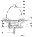
- a meniscus 5 is placed in the meniscus cylinder 6 during the measurement of the sample 1 generated.
- the overflow cylinder 2 with the sample support 3 arranged in the test plane for the Sample 1 arranged in such a way that the sample support 3 defines in relation to the overflow edge 13 of the meniscus cylinder 6 approximately with the height of the meniscus 5 vertically with an offset is spaced.
- the height of the meniscus 5 extends above the Overflow cylinder 2 with sample support 3 and is with the compensating nozzle 14 and the controllable Microdosing pump 9 set.
- the flow distributor 15 ensures a strong calming of the inflowing test liquid 7, so that the meniscus 5 with an almost flat surface formed.
- meniscus 5 wets sample 1 and Test liquid 7 runs over the overflow edge 13 of the meniscus cylinder 6 and reaches one on Overflow edge 7 arranged temperature sensor 23, the temperature of the test liquid 7th measures and signals the start of the measuring time for determining the degree of sizing.
- the sensor 12 consists of a tube in which a photoelectric sensor or Semiconductor radiation receiver with a photodiode and / or an optoelectronic Detection device with a CCD video camera 20 and an optical system 19 attached are.
- the optical system 19 forms the measuring surface predetermined by the measuring aperture 18 the semiconductor radiation receiver.
- the Measuring aperture 18 as a scale for calculating the size of differently colored particles, caused by the material formation in papers used.
- the electrical light source is formed by an electroluminescent film Luminous body 16 formed, which is preferably parabolic or seen in cross section is bent like an ellipse.
- the electroluminescent luminous element 16 is in a holder 17 attached to the sample support 3 opposite, the bracket 17 pivotally mounted or arranged detachably and provided with the measuring aperture 18 to which measuring light is applied is.
- Electroluminescent luminous bodies 16 are Lambert radiators, so that those through the measuring aperture 18 predetermined measuring area is illuminated completely diffusely. With the shape of the light source and the If the semiconductor radiation receiver is arranged below 0 °, the measurement geometry is d / 0 ° according to DIN 5033 realized.
- the radiation range of the electroluminescence - Luminous body 16 can be selected, thereby also emitting monochromatic Electroluminescent illuminant 16 is used.
- Electroluminescent illuminant 16 only an extremely low heat so that the sample 1 does not heat up during the measurement becomes.
- the measuring aperture 18 limits the measuring area on the sample 1 to a predetermined dimension. She is but also a benchmark for various calculations in image processing such as B. the size of the differently colored particles due to the material formation in paper and Coloring profile of the fabric formation.
- the control computer 11 shown in Figure 1 takes over the operator guidance on the display and Keyboard, control of the entire measurement process, measurement processing, calculation the degree of sizing and the display of the measuring time and the degree of sizing on the display.
- a personal computer 21 is necessary. In these cases, the standard interface of the control computer 11 with the standard interface of the personal computer 21 connected.
- the operator has prepared sample 1 in accordance with DIN 53102 and placed it on overflow cylinder 2 with sample support 3 corresponding to FIG. 1.
- the test device is switched on and the operator receives the request on the display of the control computer 11 to enter the weight per unit area of the paper to be measured in g / m 2 .
- the operator inputs 120, for example, using the keyboard of the control computer 11. Press the ENTER key to complete the entry of the basis weight. After that the operator is asked to enter the target reflectance beta (lambda) in percent. Here, 50% are preset. Other values between 20% and 80% are reasonable and possible. Once this has been done, the operator is asked to initiate the measurement, with Pressing the ENTER key starts the measurement.
- the control computer 11 switches the Electroluminescent luminous element 16 is turned on and by the sensor 12
- the reflectance beta (lambda) of sample 1 was measured and set equal to 100% and from this the Target reflectance beta (lambda) calculated at 50%. Up to this point the Level of the meniscus cylinder 6 the level shown in Figure 1 by the Compensation nozzle 14 is predetermined.
- FIG. 2 produces a meniscus 5 which wets the underside of the sample 1. With wetting forms a laminar parabolic flow profile with a radial flow direction, the immediately reached the temperature sensor 23, which triggers the actual measurement, which with the Temperature measurement begins.
- the measuring sensor 12 now measures the reflectance beta (lambda) in rapid succession Sample 1 and compares it with the calculated target reflectance beta 50% (lambda).
- the test ink now penetrates sample 1 due to the capillary forces and discolors it, so that the measured reflectance beta (lambda) decreases until it reaches the Target reflectance beta 50% (lambda) reached.
- the control computer breaks 11 the measurement switches off, the microdosing pump 9 and the electroluminescence Luminous body 16 and calculates the measurement time t 50%, corrects this if there is a deviation from the Standard temperature, if necessary, and calculates the degree of sizing e.g. after one Algorithm of the institute for graphic technology für.
- the values of the measuring time t 50% and the Degree of sizing or the number of sizing are shown on the display of the control computer 11 displayed.
- the measured values can also be sent to the personal computer via standard interfaces 21 are transferred, which are then processed and stored in an expert system.
- test liquid 7 flows through the Compensation nozzle 14 in the overflow cylinder 2 with sample support 3, the level in Meniscus cylinder 6 lowers and a new measurement can be triggered.
- a CCD video camera 20 is used instead of a photodiode, this is used with the Image processing card of the personal computer 21 and the personal computer 21 via the Standard interfaces connected to the control computer 11.
- the measurement is from Personal computer 21 triggered via the control computer 11 and takes place in principle in the same Way as described.
- the luminance signal Ly of the CCD - Video camera 20 used for the measurement and so pictures are taken in quick succession and with respect to the luminance signal Ly with the 50% rated luminance signal Ly des Image of the unwetted sample 1 (setpoint) compared.
- the Personal computer 21 the last picture and aborts the measurement via the control computer 11, calculates the measuring time t 50% and the degree of sizing or number of sizing.
- the soaking profile of the measuring surface which allows conclusions to be drawn about the material formation, the statistical distribution of the luminance via the measuring surface and the statistical distribution of the differently colored particles, caused by the formation of substances in papers, determined over the measuring surface and shown.
Landscapes
- Health & Medical Sciences (AREA)
- Life Sciences & Earth Sciences (AREA)
- Chemical & Material Sciences (AREA)
- Engineering & Computer Science (AREA)
- Food Science & Technology (AREA)
- Medicinal Chemistry (AREA)
- Physics & Mathematics (AREA)
- Analytical Chemistry (AREA)
- Biochemistry (AREA)
- General Health & Medical Sciences (AREA)
- General Physics & Mathematics (AREA)
- Immunology (AREA)
- Pathology (AREA)
- Investigating Or Analysing Materials By Optical Means (AREA)
- Investigating Or Analysing Materials By The Use Of Chemical Reactions (AREA)
- Sampling And Sample Adjustment (AREA)
Abstract
Description
- Figur 1
- den Aufbau eines Prüfgerätes und
- Figur 2
- die Darstellung des Meniskuszylinders und die Anordnung der Probe mit der elektrischen Lichtquelle in schematischer Darstellung
Claims (14)
- Prüfgerät zur fotoelektrischen Prüfung des Leimungsgrades und der Saugfähigkeit von Proben aus Papier, Pappe, Filtermaterial oder einem anderen saugfähigen Material mit Hilfe einer Prüfflüssigkeit sowie unter Verwendung einer horizontal in einer Prüfebene angeordneten und mit einem elastischen Druckring gehaltenen Probe, gekennzeichnet durch einen ortsfesten, über eine Zulaufleitung (10) mit einer Mikrodosierpumpe (9) verbundenen Meniskuszylinder (6) für die Prüfflüssigkeit (7), wobei bei Inbetriebnahme der Mikrodosierpumpe (9) der Meniskuszylinder (6) mit einem aus überlaufender Prüfflüssigkeit (7) bestehenden Meniskus (5) versehen und die Probe (1) auf dem Meniskus (5) schwimmend angeordnet ist.
- Prüfgerät nach Anspruch 1, dadurch gekennzeichnet, dass der Meniskuszylinder (6) in einem Überlaufzylinder (2) für Prüfflüssigkeit (7) angeordnet ist, wobei der Überlaufzylinder (2) mittels Rücklaufleitung (22) mit der Mikrodosierpumpe (9) verbunden ist.
- Prüfgerät nach Anspruch 1 bis 2, dadurch gekennzeichnet, dass in der Rücklaufleitung ein Vorratsbehälter (8) angeordnet ist.
- Prüfgerät nach Anspruch 1 bis 3, dadurch gekennzeichnet, dass eine Ausgleichsdüse (14) in dem Meniskuszylinder (6) angeordnet ist.
- Prüfgerät nach Anspruch 1 bis 4, dadurch gekennzeichnet, dass der Überlaufzylinder (2) eine in der Prüfebene angeordnete Probenauflage (3) für die Probe (1) aufweist, die definiert gegenüber dem Überlaufrand (13) des Meniskuszylinders (6) annähernd um die Höhe des Meniskus (5) vertikal mit einem Versatz beabstandet ist.
- Prüfgerät nach Anspruch 1 bis 5, dadurch gekennzeichnet, dass der Probenauflage (3) gegenüberliegend der auf der Probe (1) aufsitzende elastische Probenhaltering (4) mit einer Halterung (17) für die elektrische Lichtquelle angeordnet ist, wobei die Halterung (17) schwenkbar gelagert oder abnehmbar angeordnet und mit einer mit Messlicht beaufschlagten Messblende (18) versehen ist.
- Prüfgerät zur fotoelektrischen Prüfung des Leimungsgrades und der Saugfähigkeit von Proben aus Papier, Pappe, Filtermaterial oder einem anderen saugfähigen Material mit Hilfe einer Prüfflüssigkeit sowie unter Verwendung einer horizontal in einer Prüfebene angeordneten und mit einem elastischen Druckring gehaltenen Probe, dadurch gekennzeichnet, dass die elektrische Lichtquelle durch einen in Folienform ausgebildeten Elektrolumineszenz - Leuchtkörper (16) gebildet wird.
- Prüfgerät nach einem oder mehreren der Ansprüche 1 bis 7, dadurch gekennzeichnet, dass der in Folienform ausgebildete Elektrolumineszenz - Leuchtkörper (16) im Querschnitt gesehen parabelförmig oder ellipsenähnlich gebogen ist.
- Prüfgerät nach einem oder mehreren der Ansprüche 1 bis 8, dadurch gekennzeichnet, dass der Elektrolumineszenz - Leuchtkörper (16) im Scheitelpunkt oberhalb der Probe (1) mit einem mit dem Steuerrechner (11) verbundenen Messwertaufnehmer (12) versehen ist.
- Prüfgerät nach einem oder mehreren der Ansprüche 1 bis 9, dadurch gekennzeichnet, dass der Messwertaufnehmer (12) einen fotoelektrischen Sensor oder einen Halbleiterstrahlungsempfänger mit einer Photodiode und / oder eine optoelektronische Erfassungseinrichtung mit einer CCD - Videokamera (20) und ein optisches System (19) enthält.
- Prüfgerät nach einem oder mehreren der Ansprüche 1 bis 10, dadurch gekennzeichnet, dass die CCD - Videokamera (20) mit der Bildverarbeitungskarte des Personalcomputers (21) und der Personalcomputer (21) über die Standardschnittstellen mit dem Steuerrechner (11) verbunden ist.
- Prüfgerät nach einem oder mehreren der Ansprüche 1 bis 11, dadurch gekennzeichnet, dass der Elektrolumineszenz - Leuchtkörper (16), der Messwertaufnehmer (12) und die Mikrodosierpumpe (9) mit dem Steuerrechner (11) zur Steuerung einer automatischen fotoelektrischen Ausmessung verbunden sind.
- Prüfgerät nach einem oder mehreren der Ansprüche 1 bis 12, dadurch gekennzeichnet, dass in dem Überlaufzylinder (2) ein die Temperatur des Prüfflüssigkeit (7) messender Temperatursensor (23) angeordnet ist.
- Prüfgerät nach einem oder mehreren der Ansprüche 1 bis 13, dadurch gekennzeichnet, dass der Temperatursensor (23) schaltungstechnisch mit dem Steuerrechner (11) verbunden ist, wobei ein Steuersignal für den Beginn der Messzeit zur Leimungsgradbestimmung abgegeben wird.
Applications Claiming Priority (2)
| Application Number | Priority Date | Filing Date | Title |
|---|---|---|---|
| DE10128643A DE10128643B4 (de) | 2001-06-15 | 2001-06-15 | Vorrichtung zur fotoelektrischen Prüfung des Leimungsgrades und der Saugfähigkeit |
| DE10128643 | 2001-06-15 |
Publications (3)
| Publication Number | Publication Date |
|---|---|
| EP1267163A2 true EP1267163A2 (de) | 2002-12-18 |
| EP1267163A3 EP1267163A3 (de) | 2005-02-23 |
| EP1267163B1 EP1267163B1 (de) | 2008-05-07 |
Family
ID=7688126
Family Applications (1)
| Application Number | Title | Priority Date | Filing Date |
|---|---|---|---|
| EP02012966A Expired - Lifetime EP1267163B1 (de) | 2001-06-15 | 2002-06-12 | Prüfgerät zur fotoelektrischen Prüfung des Leimungsgrades und der Saugfähigkeit |
Country Status (3)
| Country | Link |
|---|---|
| EP (1) | EP1267163B1 (de) |
| AT (1) | ATE394668T1 (de) |
| DE (2) | DE10128643B4 (de) |
Family Cites Families (4)
| Publication number | Priority date | Publication date | Assignee | Title |
|---|---|---|---|---|
| DD20498A3 (de) * | 1957-07-30 | 1960-12-21 | ||
| US5483078A (en) * | 1994-04-14 | 1996-01-09 | Cytec Technology Corp. | Ink penetrometer having fiber optic cables and stationary ink paddle |
| DE4422861C2 (de) * | 1994-06-30 | 1996-05-09 | Honeywell Ag | Vorrichtung zur Bestimmung von Materialeigenschaften von bewegtem blattförmigem Material |
| DE19628562A1 (de) * | 1996-07-16 | 1998-01-22 | Boehringer Mannheim Gmbh | Analysesystem mit Mitteln zur Erkennung von Unterdosierungen |
-
2001
- 2001-06-15 DE DE10128643A patent/DE10128643B4/de not_active Expired - Fee Related
-
2002
- 2002-06-12 EP EP02012966A patent/EP1267163B1/de not_active Expired - Lifetime
- 2002-06-12 DE DE50212205T patent/DE50212205D1/de not_active Expired - Fee Related
- 2002-06-12 AT AT02012966T patent/ATE394668T1/de not_active IP Right Cessation
Also Published As
| Publication number | Publication date |
|---|---|
| DE10128643B4 (de) | 2004-08-05 |
| EP1267163A3 (de) | 2005-02-23 |
| EP1267163B1 (de) | 2008-05-07 |
| DE10128643A1 (de) | 2003-04-24 |
| ATE394668T1 (de) | 2008-05-15 |
| DE50212205D1 (de) | 2008-06-19 |
Similar Documents
| Publication | Publication Date | Title |
|---|---|---|
| DE69635705T2 (de) | Prüfverfahren mit flüssigkeitsansaugung und mit diesem verfahren kontrolliertes abgabegerät | |
| DE69317103T3 (de) | Beleuchtungssystem zur Inspektion von Kontaktlinsen | |
| EP0619476A1 (de) | Vorrichtung zur Detektion einer Flüssigkeitphasengrenze in einem lichtdurchlässigen Messrohr | |
| DE19754765C1 (de) | Kontaktwinkel-Meßvorrichtung | |
| DE2717089B2 (de) | Anzeigevorrichtung zur Erfassung des Pegelstandes von Flüssigkeiten in Flüssigkeitsbehältern | |
| EP0418746A1 (de) | Verfahren und Vorrichtung zur Bestimmung des Augeninnendrucks o. dgl. | |
| DE1941572A1 (de) | Vorrichtung und Verfahren fuer die photometrische Analyse von Fluessigkeiten | |
| EP2955500A1 (de) | Kontaktwinkelmessgerät | |
| DE2018068C3 (de) | ||
| DE69527465T2 (de) | Überwachungsverfahren einer Färbelösung für Partikelanalysen und Kalibrierungsverfahren von Partikelanalysen | |
| WO2020225433A1 (de) | Inline-refraktometer, insbesondere zur ermittlung der wasseranteile einer flüssigkeit, insbesondere eines kühlschmierstoffes | |
| DE69705937T2 (de) | Optisches gerät | |
| EP2133668A1 (de) | Zerstörungsfreie Messung des Füllvolumens eines mit einer Flüssigkeit gefüllten Behälters | |
| DE2136072A1 (de) | Meßgerät zur Erfassung der Beladung eines Gases mit kleinen flüssigen oder festen Partikeln | |
| DE4119346A1 (de) | Verfahren und vorrichtung zur bestimmung der gaskonzentration | |
| DE3039475A1 (de) | Aufnahme- bzw. uebertragungsvorrichtung zur entnahme von fluessigkeiten, insbesondere im klinisch-chemischen bereich | |
| EP1267163A2 (de) | Prüfgerät zur fotoelektrischen Prüfung des Leimungsgrades und der Saugfähigkeit | |
| DE2165697A1 (de) | Vorrichtung zur Ermittlung von in einem Raum suspendierten Teilchen, msbe sondere Rauchgasanzeiger | |
| DE3127560C2 (de) | Gerät zum Erfassen und Messen der Blutgerinnungszeit mit einem zur Aufnahme der Meßküvette dienenden temperierbaren Metallblock, einer Rühreinrichtung und einer lichtoptischen Trübungsmeßeinrichtung | |
| DE3441317A1 (de) | Einrichtung zur messung der grenzflaechenspannung | |
| DE1203980B (de) | Einrichtung zum Messen und UEberwachen des Brechungsindexes von Fluessigkeiten od. dgl. | |
| EP1943930B1 (de) | Getränkemaschine | |
| DE2855651C2 (de) | Schaltungseinrichtung für die photoelektrische Abtastung eines Flüssigkeitsstandes | |
| DE69504890T2 (de) | Vorrichtung zur Feststellung von Fremdstoffen in einem Kunststoffharz | |
| DE69112196T2 (de) | Wasserqualitätsprüfer. |
Legal Events
| Date | Code | Title | Description |
|---|---|---|---|
| PUAI | Public reference made under article 153(3) epc to a published international application that has entered the european phase |
Free format text: ORIGINAL CODE: 0009012 |
|
| AK | Designated contracting states |
Kind code of ref document: A2 Designated state(s): AT BE CH CY DE DK ES FI FR GB GR IE IT LI LU MC NL PT SE TR |
|
| AX | Request for extension of the european patent |
Free format text: AL;LT;LV;MK;RO;SI |
|
| PUAL | Search report despatched |
Free format text: ORIGINAL CODE: 0009013 |
|
| 17P | Request for examination filed |
Effective date: 20041203 |
|
| AK | Designated contracting states |
Kind code of ref document: A3 Designated state(s): AT BE CH CY DE DK ES FI FR GB GR IE IT LI LU MC NL PT SE TR |
|
| AX | Request for extension of the european patent |
Extension state: AL LT LV MK RO SI |
|
| AKX | Designation fees paid |
Designated state(s): AT DE GB NL SE |
|
| GRAP | Despatch of communication of intention to grant a patent |
Free format text: ORIGINAL CODE: EPIDOSNIGR1 |
|
| GRAS | Grant fee paid |
Free format text: ORIGINAL CODE: EPIDOSNIGR3 |
|
| GRAA | (expected) grant |
Free format text: ORIGINAL CODE: 0009210 |
|
| AK | Designated contracting states |
Kind code of ref document: B1 Designated state(s): AT DE GB NL SE |
|
| REG | Reference to a national code |
Ref country code: GB Ref legal event code: FG4D Free format text: NOT ENGLISH |
|
| REF | Corresponds to: |
Ref document number: 50212205 Country of ref document: DE Date of ref document: 20080619 Kind code of ref document: P |
|
| PG25 | Lapsed in a contracting state [announced via postgrant information from national office to epo] |
Ref country code: NL Free format text: LAPSE BECAUSE OF FAILURE TO SUBMIT A TRANSLATION OF THE DESCRIPTION OR TO PAY THE FEE WITHIN THE PRESCRIBED TIME-LIMIT Effective date: 20080507 |
|
| NLV1 | Nl: lapsed or annulled due to failure to fulfill the requirements of art. 29p and 29m of the patents act | ||
| PG25 | Lapsed in a contracting state [announced via postgrant information from national office to epo] |
Ref country code: SE Free format text: LAPSE BECAUSE OF FAILURE TO SUBMIT A TRANSLATION OF THE DESCRIPTION OR TO PAY THE FEE WITHIN THE PRESCRIBED TIME-LIMIT Effective date: 20080807 |
|
| PLBE | No opposition filed within time limit |
Free format text: ORIGINAL CODE: 0009261 |
|
| STAA | Information on the status of an ep patent application or granted ep patent |
Free format text: STATUS: NO OPPOSITION FILED WITHIN TIME LIMIT |
|
| 26N | No opposition filed |
Effective date: 20090210 |
|
| GBPC | Gb: european patent ceased through non-payment of renewal fee |
Effective date: 20080807 |
|
| PG25 | Lapsed in a contracting state [announced via postgrant information from national office to epo] |
Ref country code: AT Free format text: LAPSE BECAUSE OF NON-PAYMENT OF DUE FEES Effective date: 20080612 |
|
| PG25 | Lapsed in a contracting state [announced via postgrant information from national office to epo] |
Ref country code: GB Free format text: LAPSE BECAUSE OF NON-PAYMENT OF DUE FEES Effective date: 20080807 |
|
| PGFP | Annual fee paid to national office [announced via postgrant information from national office to epo] |
Ref country code: DE Payment date: 20091217 Year of fee payment: 8 |
|
| PG25 | Lapsed in a contracting state [announced via postgrant information from national office to epo] |
Ref country code: DE Free format text: LAPSE BECAUSE OF NON-PAYMENT OF DUE FEES Effective date: 20110101 |