EP1266773A2 - Automobile body frame structure - Google Patents
Automobile body frame structure Download PDFInfo
- Publication number
- EP1266773A2 EP1266773A2 EP02013151A EP02013151A EP1266773A2 EP 1266773 A2 EP1266773 A2 EP 1266773A2 EP 02013151 A EP02013151 A EP 02013151A EP 02013151 A EP02013151 A EP 02013151A EP 1266773 A2 EP1266773 A2 EP 1266773A2
- Authority
- EP
- European Patent Office
- Prior art keywords
- frame
- sub
- rubber bush
- joint
- bush joint
- Prior art date
- Legal status (The legal status is an assumption and is not a legal conclusion. Google has not performed a legal analysis and makes no representation as to the accuracy of the status listed.)
- Granted
Links
Images


Classifications
-
- B—PERFORMING OPERATIONS; TRANSPORTING
- B62—LAND VEHICLES FOR TRAVELLING OTHERWISE THAN ON RAILS
- B62D—MOTOR VEHICLES; TRAILERS
- B62D21/00—Understructures, i.e. chassis frame on which a vehicle body may be mounted
- B62D21/11—Understructures, i.e. chassis frame on which a vehicle body may be mounted with resilient means for suspension, e.g. of wheels or engine; sub-frames for mounting engine or suspensions
-
- B—PERFORMING OPERATIONS; TRANSPORTING
- B60—VEHICLES IN GENERAL
- B60G—VEHICLE SUSPENSION ARRANGEMENTS
- B60G7/00—Pivoted suspension arms; Accessories thereof
- B60G7/02—Attaching arms to sprung part of vehicle
-
- B—PERFORMING OPERATIONS; TRANSPORTING
- B60—VEHICLES IN GENERAL
- B60G—VEHICLE SUSPENSION ARRANGEMENTS
- B60G2200/00—Indexing codes relating to suspension types
- B60G2200/10—Independent suspensions
- B60G2200/14—Independent suspensions with lateral arms
- B60G2200/154—Independent suspensions with lateral arms the lateral arm having an L-shape
-
- B—PERFORMING OPERATIONS; TRANSPORTING
- B60—VEHICLES IN GENERAL
- B60G—VEHICLE SUSPENSION ARRANGEMENTS
- B60G2204/00—Indexing codes related to suspensions per se or to auxiliary parts
- B60G2204/40—Auxiliary suspension parts; Adjustment of suspensions
- B60G2204/44—Centering or positioning means
- B60G2204/4404—Retainers for holding a fixing element, e.g. bushing, nut, bolt etc., until it is tightly fixed in position
-
- B—PERFORMING OPERATIONS; TRANSPORTING
- B60—VEHICLES IN GENERAL
- B60G—VEHICLE SUSPENSION ARRANGEMENTS
- B60G2206/00—Indexing codes related to the manufacturing of suspensions: constructional features, the materials used, procedures or tools
- B60G2206/01—Constructional features of suspension elements, e.g. arms, dampers, springs
- B60G2206/012—Hollow or tubular elements
-
- B—PERFORMING OPERATIONS; TRANSPORTING
- B60—VEHICLES IN GENERAL
- B60G—VEHICLE SUSPENSION ARRANGEMENTS
- B60G2206/00—Indexing codes related to the manufacturing of suspensions: constructional features, the materials used, procedures or tools
- B60G2206/01—Constructional features of suspension elements, e.g. arms, dampers, springs
- B60G2206/10—Constructional features of arms
- B60G2206/122—Constructional features of arms the arm having L-shape
-
- B—PERFORMING OPERATIONS; TRANSPORTING
- B60—VEHICLES IN GENERAL
- B60G—VEHICLE SUSPENSION ARRANGEMENTS
- B60G2206/00—Indexing codes related to the manufacturing of suspensions: constructional features, the materials used, procedures or tools
- B60G2206/01—Constructional features of suspension elements, e.g. arms, dampers, springs
- B60G2206/70—Materials used in suspensions
- B60G2206/72—Steel
- B60G2206/722—Plates
-
- B—PERFORMING OPERATIONS; TRANSPORTING
- B60—VEHICLES IN GENERAL
- B60G—VEHICLE SUSPENSION ARRANGEMENTS
- B60G2206/00—Indexing codes related to the manufacturing of suspensions: constructional features, the materials used, procedures or tools
- B60G2206/01—Constructional features of suspension elements, e.g. arms, dampers, springs
- B60G2206/80—Manufacturing procedures
- B60G2206/81—Shaping
- B60G2206/8103—Shaping by folding or bending
-
- B—PERFORMING OPERATIONS; TRANSPORTING
- B60—VEHICLES IN GENERAL
- B60G—VEHICLE SUSPENSION ARRANGEMENTS
- B60G2206/00—Indexing codes related to the manufacturing of suspensions: constructional features, the materials used, procedures or tools
- B60G2206/01—Constructional features of suspension elements, e.g. arms, dampers, springs
- B60G2206/80—Manufacturing procedures
- B60G2206/81—Shaping
- B60G2206/811—Shaping by cutting
-
- B—PERFORMING OPERATIONS; TRANSPORTING
- B60—VEHICLES IN GENERAL
- B60G—VEHICLE SUSPENSION ARRANGEMENTS
- B60G2206/00—Indexing codes related to the manufacturing of suspensions: constructional features, the materials used, procedures or tools
- B60G2206/01—Constructional features of suspension elements, e.g. arms, dampers, springs
- B60G2206/80—Manufacturing procedures
- B60G2206/82—Joining
- B60G2206/8201—Joining by welding
Definitions
- the present invention relates to an automobile body frame structure in which a suspension arm is supported in a sub-frame and the sub-frame is mounted on a main frame.
- the engine and the suspension arm are mounted on a sub-frame in advance so as to form a sub-assembly, and the sub-frame is then mounted as a unit on the main frame of the body.
- separate bolts are used to secure a rubber bush joint provided on the base of the suspension arm to the sub-frame and to secure the sub-frame to the main frame, and the bolts are not shared.
- a total of eight bolts are required, that is, two bolts on the left and two on the right for securing two rubber bush joints of each of left and right suspension arms (lower arms) and two bolts on the left and two on the right for securing the sub-frame to left and right front side frames (main frames). If these 8 bolts can be decreased in number, both the number of components and the number of assembling steps can be reduced, thereby contributing to a reduction in the cost.
- the present invention has been achieved in view of the above-mentioned circumstances, and it is an object of the present invention to reduce the number of bolts required for supporting a suspension arm in a sub-frame and mounting the sub-frame on a main frame.
- an automobile body frame structure in which a suspension arm is supported in a sub-frame and the sub-frame is mounted on a main frame, wherein the axis of at least one joint, among a plurality of joints of the suspension arm supported in the sub-frame, is positioned in a vertical direction, and a bolt that is used for securing this joint to the sub-frame is also used to secure the sub-frame to the main frame.
- the bolt that is used to secure said one joint to the sub-frame is also used to secure the sub-frame to the main frame, the three components of the joint, the sub-frame, and the main frame can be secured together by one bolt, thus reducing the number of bolts and the number of assembling steps, thereby contributing to a reduction in the cost.
- an automobile body frame structure wherein said one joint is a rubber bush joint in which an inner tube and an outer tube are connected to each other by a rubber bush, and the sub-frame includes a positioning part for positioning the inner tube.
- the rubber bush joint can be positioned precisely relative to the sub-frame.
- the suspension arm of the present invention corresponds to a lower arm 11 of an embodiment
- the joints of the present invention correspond to front and rear rubber bush joints 12 and 13 of the embodiment
- the positioning part of the present invention corresponds to a positioning flange 22a, a positioning step 22b, and a positioning flange 33a of the embodiment
- the sub-frame of the present invention corresponds to a front sub-frame FS of the embodiment
- the main frame of the present invention corresponds to front side frames FL and FR of the embodiment.
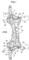
- a pair of left and right front side frames FL and FR are disposed in a front part of an automobile body in the longitudinal direction, and a front sub-frame FS is secured to the lower faces of the front side frames FL and FR so as to bridge them.
- Mounted in advance on the upper face of the front sub-frame FS are an engine and a transmission (not illustrated), and attached to each of the left and right sides of the front sub-frame FS is a front suspension lower arm 11.
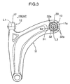
- the lower arm 11 is produced by press-forming a metal sheet and is a so-called A type arm.
- the lower arm 11 includes a front rubber bush joint 12 and a rear rubber bush joint 13 on the side facing the front sub-frame FS, and a ball joint (not illustrated) that is connected to a knuckle at the end on the side opposite to the front sub-frame FS.
- the axis L1 of the front rubber bush joint 12 is in the longitudinal direction of the vehicle body, and the axis L2 of the rear rubber bush joint 13 is in the vertical direction.
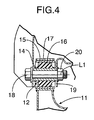
- the front rubber bush joint 12 is formed by connecting a metal inner tube 14 and a metal outer tube 15 via a rubber bush 16.
- the outer tube 15 is inserted under pressure into a support tube 17 provided in a front part of each of the lower arms 11.
- a bolt 18 running through the inner tube 14 in the longitudinal direction further runs through a support 19 and is tightened with a nut 20, the support 19 having an inverted U-shaped cross section and being integrally formed with the front sub-frame FS at a position toward the front end of each of the left and right sides of the frame FS.
- the front sub-frame FS is basically formed by joining an upper panel 21 and a lower panel 22 at their peripheries.
- a body mounting part 23 projects obliquely upward from the upper face of each of the left and right sides of the upper panel 21, the body mounting part 23 being a member separate from the upper panel 21.
- a mounting bracket 24 is welded to the upper face of each of the body mounting parts 23.
- the left and right front side frames FL and FR are curved so that their front parts are higher than their rear parts, and the lower face of the higher part of each of the left and right front side frames FL and FR is in contact with the upper face of the corresponding mounting bracket 24.
- a bolt 25 is inserted from beneath into each of the body mounting parts 23 of the front sub-frame FS, runs through both the corresponding mounting bracket 24 welded to the upper face of the body mounting part 23 and a mounting bracket 26 welded to the lower face of the corresponding one of the left and right front side frames FL and FR, and is tightened with a nut 29 welded to the interior of the mounting bracket 26.
- This bolt 25 runs through a collar 28 provided within the mounting bracket 24 of the front sub-frame FS.
- the rear rubber bush joint 13 is formed by connecting a metal inner tube 30 and a metal outer tube 31 via a rubber bush 32, and four cavities 32a are formed in the rubber bush 31.
- the upper panel 21 and the lower panel 22 of the front sub-frame FS are superimposed on each other at positions near the rear ends of the left and right sides, and a sheet-form support bracket 33 is welded to the lower face of the lower panel 22.
- a positioning flange 22a is formed by bending the periphery of the lower panel 22 downward, and a positioning step 22b is formed by cutting a part of the lower panel 22.
- the positioning flange 22a and the positioning step 22b position the upper end of the inner tube 30 of the rear rubber bush joint 13.
- the lower end of the inner tube 30 of the rear rubber bush joint 13 is positioned by a positioning flange 33a formed by bending upward the periphery of the support bracket 33.
- the outer tube 31 of the rear rubber bush joint 13 is inserted under pressure into a circular mounting hole 11a formed in the rear end of the lower arm 11.
- a bolt 34 is inserted from beneath into each of the support brackets 33 of the front sub-frame FS, runs through the inner tube 30 of the rear rubber bush joint 13, the lower panel 22 and the upper panel 21 of the front sub-frame FS, and the corresponding mounting bracket 35 provided on the lower face of each of the left and right front side frames FL and FR, and is tightened with a nut 37 welded to the interior of the mounting bracket 35. Since the inner diameter of the inner tube 30 of the rear rubber bush joint 13 is larger than the outer diameter of the bolt 34, the position at which the front sub-frame FS and the rear rubber bush joint 13 are mounted on each of the front side frames FL and FR can be finely adjusted.
- the number of bolts can be reduced by two in comparison with a case in which a front sub-frame FS and front side frames FL and FR are joined to each other by bolts that are separate from two bolts 34 used for mounting rear rubber bush joints 13 on the front sub-frame FS, so that the number of assembling steps and the cost can be reduced.
- the position of the rear rubber bush joint 13 can be precisely determined with respect to the front sub-frame FS.
- the present invention is applied to the front sub-frame FS, but it can be applied to a rear sub-frame on which a fuel tank and a rear suspension are mounted.
- the lower arms 11 are illustrated as an example of the suspension arm, but the present invention can be applied to any suspension arm as well as the lower arms 11.
- the joint for joining the suspension arm to the sub-frame is not limited to the rubber bush joint, and any type of joint can be employed.
- An automobile body frame structure has an arrangement in which a suspension lower arm is supported in a front sub-frame and the front sub-frame is mounted on main frames.
- a suspension lower arm is supported in a front sub-frame and the front sub-frame is mounted on main frames.
- the axis of the rear rubber bush joint is in the vertical direction. Securing the front sub-frame to the main frame using a bolt that is used for mounting the rubber bush joint on the front sub-frame reduces the number of bolts, thereby reducing the number of assembling steps and the cost.
Landscapes
- Engineering & Computer Science (AREA)
- Mechanical Engineering (AREA)
- Chemical & Material Sciences (AREA)
- Combustion & Propulsion (AREA)
- Transportation (AREA)
- Body Structure For Vehicles (AREA)
- Vehicle Body Suspensions (AREA)
Abstract
Description
Claims (2)
- An automobile body frame structure comprising a sub-frame, a suspension arm supported in the sub-frame, and a main frame on which the sub-frame is mounted, the suspension arm comprising:a plurality of joints, the axis of at least one of the joints being disposed in the vertical direction; anda bolt for securing said joint to the sub-frame, the bolt being also used for securing the sub-frame to the main frame.
- The automobile body frame structure according to Claim 1 wherein said joint is a rubber bush joint in which an inner tube and an outer tube are connected to each other via a rubber bush, and said sub-frame comprises a positioning part for positioning the inner tube.
Priority Applications (1)
| Application Number | Priority Date | Filing Date | Title |
|---|---|---|---|
| EP08009245A EP1982856B1 (en) | 2001-06-15 | 2002-06-14 | Automobile body frame structure |
Applications Claiming Priority (2)
| Application Number | Priority Date | Filing Date | Title |
|---|---|---|---|
| JP2001182509 | 2001-06-15 | ||
| JP2001182509A JP4007774B2 (en) | 2001-06-15 | 2001-06-15 | Auto body frame structure |
Related Child Applications (1)
| Application Number | Title | Priority Date | Filing Date |
|---|---|---|---|
| EP08009245A Division EP1982856B1 (en) | 2001-06-15 | 2002-06-14 | Automobile body frame structure |
Publications (3)
| Publication Number | Publication Date |
|---|---|
| EP1266773A2 true EP1266773A2 (en) | 2002-12-18 |
| EP1266773A3 EP1266773A3 (en) | 2006-06-07 |
| EP1266773B1 EP1266773B1 (en) | 2009-02-11 |
Family
ID=19022602
Family Applications (2)
| Application Number | Title | Priority Date | Filing Date |
|---|---|---|---|
| EP08009245A Expired - Lifetime EP1982856B1 (en) | 2001-06-15 | 2002-06-14 | Automobile body frame structure |
| EP20020013151 Expired - Lifetime EP1266773B1 (en) | 2001-06-15 | 2002-06-14 | Automobile body frame structure |
Family Applications Before (1)
| Application Number | Title | Priority Date | Filing Date |
|---|---|---|---|
| EP08009245A Expired - Lifetime EP1982856B1 (en) | 2001-06-15 | 2002-06-14 | Automobile body frame structure |
Country Status (6)
| Country | Link |
|---|---|
| EP (2) | EP1982856B1 (en) |
| JP (1) | JP4007774B2 (en) |
| CN (1) | CN1195649C (en) |
| BR (1) | BR0202262B1 (en) |
| DE (2) | DE60237730D1 (en) |
| TW (1) | TW546215B (en) |
Cited By (5)
| Publication number | Priority date | Publication date | Assignee | Title |
|---|---|---|---|---|
| US7654543B2 (en) | 2004-09-14 | 2010-02-02 | Daihatsu Motor Co., Ltd. | Vehicle suspension arm supporting structure |
| EP2263890A1 (en) * | 2004-03-31 | 2010-12-22 | Honda Motor Co., Ltd. | Subframe for vehicle, and bush mounting arrangement therefor |
| US8746718B2 (en) | 2010-06-30 | 2014-06-10 | Mazda Motor Corporation | Suspension mounting structure for vehicle |
| CN104249613A (en) * | 2013-06-27 | 2014-12-31 | 铃木株式会社 | Front suspension device |
| FR3025771A1 (en) * | 2014-09-16 | 2016-03-18 | Renault Sas | "FRONT STRUCTURE OF MOTOR VEHICLE WITH SIMPLIFIED CRADLE" |
Families Citing this family (25)
| Publication number | Priority date | Publication date | Assignee | Title |
|---|---|---|---|---|
| KR100599263B1 (en) * | 2003-10-29 | 2006-07-13 | 현대자동차주식회사 | Mounting structure of the vehicle front suspension |
| JP4534136B2 (en) * | 2004-10-20 | 2010-09-01 | マツダ株式会社 | Front suspension device for automobile |
| JP2006182287A (en) * | 2004-12-28 | 2006-07-13 | Mazda Motor Corp | Front suspension device |
| WO2007031059A2 (en) * | 2005-09-13 | 2007-03-22 | Ksm Castings Gmbh | Auxiliary frame, particularly for motor vehicles |
| JP4901688B2 (en) * | 2007-10-17 | 2012-03-21 | 本田技研工業株式会社 | Body front structure |
| JP5707124B2 (en) * | 2010-12-27 | 2015-04-22 | フタバ産業株式会社 | Suspension frame structure |
| JP5946996B2 (en) * | 2011-03-16 | 2016-07-06 | フタバ産業株式会社 | Suspension frame structure |
| CN103562051B (en) * | 2011-04-27 | 2016-05-25 | 三菱自动车工业株式会社 | Carrier frame |
| JP5822130B2 (en) * | 2011-11-29 | 2015-11-24 | スズキ株式会社 | Suspension frame peripheral structure |
| JP5870867B2 (en) * | 2012-07-17 | 2016-03-01 | トヨタ自動車株式会社 | Suspension member and vehicle front structure including the same |
| DE102012223292A1 (en) * | 2012-12-14 | 2014-06-18 | Bayerische Motoren Werke Aktiengesellschaft | Motor vehicle with an axle carrier |
| JP6057171B2 (en) * | 2013-03-01 | 2017-01-11 | スズキ株式会社 | Suspension frame structure |
| JP5949600B2 (en) * | 2013-03-05 | 2016-07-06 | マツダ株式会社 | Front body structure of the vehicle |
| JP6136482B2 (en) * | 2013-04-04 | 2017-05-31 | スズキ株式会社 | Suspension arm mounting structure |
| JP6209893B2 (en) * | 2013-08-01 | 2017-10-11 | スズキ株式会社 | Suspension arm fixing structure |
| AU2014370931A1 (en) * | 2013-12-27 | 2016-07-14 | Honda Motor Co.,Ltd. | Sub-frame structure |
| CN104085448B (en) * | 2014-07-17 | 2016-06-01 | 奇瑞汽车股份有限公司 | The positioning and mounting structure of automobile front subframe and automobile |
| JP6460460B2 (en) * | 2014-12-12 | 2019-01-30 | 三菱自動車工業株式会社 | Front cross member mounting structure |
| JP6269638B2 (en) * | 2015-11-11 | 2018-01-31 | マツダ株式会社 | Rear subframe structure |
| JP6237866B1 (en) * | 2016-11-22 | 2017-11-29 | マツダ株式会社 | Front subframe structure |
| JP6483756B2 (en) * | 2017-06-05 | 2019-03-13 | 本田技研工業株式会社 | Suspension arm support structure |
| JP2019031234A (en) * | 2017-08-09 | 2019-02-28 | 三菱自動車工業株式会社 | Cross member mounting structure |
| JP7038220B2 (en) * | 2018-09-27 | 2022-03-17 | 本田技研工業株式会社 | Subframe structure |
| CN116374008B (en) * | 2023-05-05 | 2026-04-03 | 北京汽车集团越野车有限公司 | Suspension mounting components, engine compartment and vehicle |
| FR3163608A1 (en) * | 2024-06-20 | 2025-12-26 | Stellantis Auto Sas | MOTOR VEHICLE WITH FRONT CRADLE RECEPTING SUSPENSION ARMS |
Family Cites Families (19)
| Publication number | Priority date | Publication date | Assignee | Title |
|---|---|---|---|---|
| DE2536060C2 (en) * | 1975-08-13 | 1987-05-27 | Volkswagenwerk Ag, 3180 Wolfsburg | Wheel suspension for automobiles |
| DE3441560A1 (en) * | 1984-11-14 | 1986-05-22 | Adam Opel AG, 6090 Rüsselsheim | Rear axle |
| DE8616013U1 (en) * | 1986-06-13 | 1987-04-30 | Audi AG, 8070 Ingolstadt | Device for linking a wheel guide member |
| EP0265675B1 (en) * | 1986-10-04 | 1991-11-13 | Volkswagen Aktiengesellschaft | Assembly comprising an auxiliary chassis with pivotally mounted suspension arms |
| JPS63180509A (en) * | 1987-01-23 | 1988-07-25 | Toyota Motor Corp | Structure for supporting suspension member of vehicle |
| JPH05139131A (en) * | 1991-11-20 | 1993-06-08 | Toyota Motor Corp | Vehicle-body side mounting structure for strut bar |
| JP2952794B2 (en) * | 1991-12-10 | 1999-09-27 | 本田技研工業株式会社 | Method of manufacturing suspension member for vehicle |
| JP3226142B2 (en) * | 1993-12-24 | 2001-11-05 | スズキ株式会社 | Automotive subframe structure |
| JP3265439B2 (en) * | 1994-12-09 | 2002-03-11 | ダイハツ工業株式会社 | Suspension lower arm mounting structure |
| JPH0966720A (en) * | 1995-08-30 | 1997-03-11 | Toyota Motor Corp | Vehicle suspension system |
| JPH10316012A (en) * | 1997-05-20 | 1998-12-02 | Toyota Motor Corp | Suspension arm assembly structure |
| FR2765154B1 (en) * | 1997-06-27 | 1999-07-23 | Renault | ARRANGEMENT FOR THE SUSPENSION OF THE CRADLE OF A FRONT TRAIN OF A MOTOR VEHICLE |
| FR2767750B1 (en) * | 1997-08-29 | 1999-10-08 | Peugeot | CONNECTION DEVICE FOR CONNECTING TO THE STRUCTURE OF A VEHICLE A CRADLE AND A SUSPENSION ARM |
| JPH11334332A (en) * | 1998-05-28 | 1999-12-07 | Daihatsu Motor Co Ltd | Front suspension |
| JP2000130485A (en) * | 1998-10-29 | 2000-05-12 | Musashi Seimitsu Ind Co Ltd | Bush and arm connecting structure |
| JP2000343921A (en) * | 1999-06-03 | 2000-12-12 | Daihatsu Motor Co Ltd | Supporting device of suspension arm |
| KR20010019320A (en) * | 1999-08-26 | 2001-03-15 | 이계안 | Structure of rear wheel cross member |
| US6409216B2 (en) * | 2000-03-17 | 2002-06-25 | Suzuki Motor Corporation | Suspension frame construction |
| FR2810275B1 (en) * | 2000-06-14 | 2002-09-20 | Peugeot Citroen Automobiles Sa | DEVICE FOR FIXING A BEARING SUPPORT OF AN ANTI-TIP BAR TO A STRUCTURAL ELEMENT OF A MOTOR VEHICLE |
-
2001
- 2001-06-15 JP JP2001182509A patent/JP4007774B2/en not_active Expired - Fee Related
-
2002
- 2002-06-14 EP EP08009245A patent/EP1982856B1/en not_active Expired - Lifetime
- 2002-06-14 DE DE60237730T patent/DE60237730D1/en not_active Expired - Lifetime
- 2002-06-14 CN CNB021225478A patent/CN1195649C/en not_active Expired - Fee Related
- 2002-06-14 EP EP20020013151 patent/EP1266773B1/en not_active Expired - Lifetime
- 2002-06-14 TW TW91113025A patent/TW546215B/en not_active IP Right Cessation
- 2002-06-14 BR BR0202262A patent/BR0202262B1/en not_active IP Right Cessation
- 2002-06-14 DE DE60231094T patent/DE60231094D1/en not_active Expired - Lifetime
Cited By (6)
| Publication number | Priority date | Publication date | Assignee | Title |
|---|---|---|---|---|
| EP2263890A1 (en) * | 2004-03-31 | 2010-12-22 | Honda Motor Co., Ltd. | Subframe for vehicle, and bush mounting arrangement therefor |
| US7654543B2 (en) | 2004-09-14 | 2010-02-02 | Daihatsu Motor Co., Ltd. | Vehicle suspension arm supporting structure |
| US8746718B2 (en) | 2010-06-30 | 2014-06-10 | Mazda Motor Corporation | Suspension mounting structure for vehicle |
| CN104249613A (en) * | 2013-06-27 | 2014-12-31 | 铃木株式会社 | Front suspension device |
| DE102014009645B4 (en) | 2013-06-27 | 2024-01-04 | Suzuki Motor Corporation | Front suspension device |
| FR3025771A1 (en) * | 2014-09-16 | 2016-03-18 | Renault Sas | "FRONT STRUCTURE OF MOTOR VEHICLE WITH SIMPLIFIED CRADLE" |
Also Published As
| Publication number | Publication date |
|---|---|
| JP2002370670A (en) | 2002-12-24 |
| EP1982856B1 (en) | 2010-09-15 |
| BR0202262A (en) | 2003-04-01 |
| JP4007774B2 (en) | 2007-11-14 |
| EP1266773B1 (en) | 2009-02-11 |
| CN1392078A (en) | 2003-01-22 |
| EP1982856A1 (en) | 2008-10-22 |
| EP1266773A3 (en) | 2006-06-07 |
| CN1195649C (en) | 2005-04-06 |
| DE60237730D1 (en) | 2010-10-28 |
| DE60231094D1 (en) | 2009-03-26 |
| TW546215B (en) | 2003-08-11 |
| BR0202262B1 (en) | 2011-07-12 |
Similar Documents
| Publication | Publication Date | Title |
|---|---|---|
| EP1266773A2 (en) | Automobile body frame structure | |
| EP1322513B1 (en) | Modular subframe assembly for a motor vehicle | |
| US5480001A (en) | Frame structure for a motorcycle | |
| US8356826B2 (en) | Suspension system for a vehicle | |
| US7896372B2 (en) | Suspension device | |
| US20030146592A1 (en) | Suspension system having reduced stress axle connection | |
| AU7256300A (en) | Steering gear frame | |
| CN101094772A (en) | Torsion beam suspension | |
| US6354627B1 (en) | Construction for suspension system mounting portions of body of vehicle | |
| JPH08169205A (en) | Integral axle tube and yoke assembly for front wheel drive axle assembly and vehicle axle assembly | |
| JP4270986B2 (en) | Torsion beam suspension | |
| JP2009166796A (en) | Vehicle suspension system | |
| JP2000272535A (en) | Vehicle subframe structure | |
| JP2006232180A (en) | Torsion beam suspension | |
| JP4585134B2 (en) | Suspension subframe support structure | |
| JP2008095861A (en) | Anti-vibration bush and link member | |
| JPH08198134A (en) | Aluminum alloy cross member | |
| JP3128678B2 (en) | Mounting structure of shock absorber | |
| JPH11115796A (en) | Suspension member | |
| JP3214783B2 (en) | Fuel tank support structure | |
| KR100312179B1 (en) | Control Arm For Automotive Vehicle | |
| JP4405376B2 (en) | Car suspension arm | |
| JP3925689B2 (en) | Hollow member | |
| JPH0976934A (en) | Rear differential case support structure of vehicle | |
| CN100448738C (en) | straddle vehicle |
Legal Events
| Date | Code | Title | Description |
|---|---|---|---|
| PUAI | Public reference made under article 153(3) epc to a published international application that has entered the european phase |
Free format text: ORIGINAL CODE: 0009012 |
|
| AK | Designated contracting states |
Kind code of ref document: A2 Designated state(s): AT BE CH CY DE DK ES FI FR GB GR IE IT LI LU MC NL PT SE TR |
|
| AX | Request for extension of the european patent |
Free format text: AL;LT;LV;MK;RO;SI |
|
| PUAL | Search report despatched |
Free format text: ORIGINAL CODE: 0009013 |
|
| AK | Designated contracting states |
Kind code of ref document: A3 Designated state(s): AT BE CH CY DE DK ES FI FR GB GR IE IT LI LU MC NL PT SE TR |
|
| AX | Request for extension of the european patent |
Extension state: AL LT LV MK RO SI |
|
| 17P | Request for examination filed |
Effective date: 20060731 |
|
| 17Q | First examination report despatched |
Effective date: 20061026 |
|
| AKX | Designation fees paid |
Designated state(s): DE FR GB |
|
| GRAP | Despatch of communication of intention to grant a patent |
Free format text: ORIGINAL CODE: EPIDOSNIGR1 |
|
| GRAS | Grant fee paid |
Free format text: ORIGINAL CODE: EPIDOSNIGR3 |
|
| GRAA | (expected) grant |
Free format text: ORIGINAL CODE: 0009210 |
|
| AK | Designated contracting states |
Kind code of ref document: B1 Designated state(s): DE FR GB |
|
| REG | Reference to a national code |
Ref country code: GB Ref legal event code: FG4D |
|
| REF | Corresponds to: |
Ref document number: 60231094 Country of ref document: DE Date of ref document: 20090326 Kind code of ref document: P |
|
| PLBE | No opposition filed within time limit |
Free format text: ORIGINAL CODE: 0009261 |
|
| STAA | Information on the status of an ep patent application or granted ep patent |
Free format text: STATUS: NO OPPOSITION FILED WITHIN TIME LIMIT |
|
| 26N | No opposition filed |
Effective date: 20091112 |
|
| PGFP | Annual fee paid to national office [announced via postgrant information from national office to epo] |
Ref country code: FR Payment date: 20100709 Year of fee payment: 9 |
|
| PGFP | Annual fee paid to national office [announced via postgrant information from national office to epo] |
Ref country code: DE Payment date: 20100610 Year of fee payment: 9 Ref country code: GB Payment date: 20100609 Year of fee payment: 9 |
|
| GBPC | Gb: european patent ceased through non-payment of renewal fee |
Effective date: 20110614 |
|
| REG | Reference to a national code |
Ref country code: FR Ref legal event code: ST Effective date: 20120229 |
|
| REG | Reference to a national code |
Ref country code: DE Ref legal event code: R119 Ref document number: 60231094 Country of ref document: DE Effective date: 20120103 |
|
| PG25 | Lapsed in a contracting state [announced via postgrant information from national office to epo] |
Ref country code: DE Free format text: LAPSE BECAUSE OF NON-PAYMENT OF DUE FEES Effective date: 20120103 Ref country code: FR Free format text: LAPSE BECAUSE OF NON-PAYMENT OF DUE FEES Effective date: 20110630 |
|
| PG25 | Lapsed in a contracting state [announced via postgrant information from national office to epo] |
Ref country code: GB Free format text: LAPSE BECAUSE OF NON-PAYMENT OF DUE FEES Effective date: 20110614 |
|
| REG | Reference to a national code |
Ref country code: GB Ref legal event code: S117 Free format text: REQUEST FILED; REQUEST FOR CORRECTION UNDER SECTION 117 FILED ON 19 SEPTEMBER 2013 |
|
| REG | Reference to a national code |
Ref country code: GB Ref legal event code: S117 Free format text: CORRECTIONS ALLOWED; REQUEST FOR CORRECTION UNDER SECTION 117 FILED ON 19 SEPTEMBER 2013 ALLOWED ON 28 JANUARY 2014 |