EP1266735A2 - Method of producing a precast slab or beam made of standard or precompressed concrete - Google Patents
Method of producing a precast slab or beam made of standard or precompressed concrete Download PDFInfo
- Publication number
- EP1266735A2 EP1266735A2 EP02012483A EP02012483A EP1266735A2 EP 1266735 A2 EP1266735 A2 EP 1266735A2 EP 02012483 A EP02012483 A EP 02012483A EP 02012483 A EP02012483 A EP 02012483A EP 1266735 A2 EP1266735 A2 EP 1266735A2
- Authority
- EP
- European Patent Office
- Prior art keywords
- article
- inclined cuts
- slab
- cuts
- hollow
- Prior art date
- Legal status (The legal status is an assumption and is not a legal conclusion. Google has not performed a legal analysis and makes no representation as to the accuracy of the status listed.)
- Granted
Links
Images

Classifications
-
- B—PERFORMING OPERATIONS; TRANSPORTING
- B28—WORKING CEMENT, CLAY, OR STONE
- B28B—SHAPING CLAY OR OTHER CERAMIC COMPOSITIONS; SHAPING SLAG; SHAPING MIXTURES CONTAINING CEMENTITIOUS MATERIAL, e.g. PLASTER
- B28B11/00—Apparatus or processes for treating or working the shaped or preshaped articles
- B28B11/14—Apparatus or processes for treating or working the shaped or preshaped articles for dividing shaped articles by cutting
-
- B—PERFORMING OPERATIONS; TRANSPORTING
- B28—WORKING CEMENT, CLAY, OR STONE
- B28B—SHAPING CLAY OR OTHER CERAMIC COMPOSITIONS; SHAPING SLAG; SHAPING MIXTURES CONTAINING CEMENTITIOUS MATERIAL, e.g. PLASTER
- B28B23/00—Arrangements specially adapted for the production of shaped articles with elements wholly or partly embedded in the moulding material; Production of reinforced objects
- B28B23/02—Arrangements specially adapted for the production of shaped articles with elements wholly or partly embedded in the moulding material; Production of reinforced objects wherein the elements are reinforcing members
- B28B23/04—Arrangements specially adapted for the production of shaped articles with elements wholly or partly embedded in the moulding material; Production of reinforced objects wherein the elements are reinforcing members the elements being stressed
- B28B23/06—Arrangements specially adapted for the production of shaped articles with elements wholly or partly embedded in the moulding material; Production of reinforced objects wherein the elements are reinforcing members the elements being stressed for the production of elongated articles
Definitions
- the present invention relates to a method of producing a precast slab or beam made of standard or pre-compressed concrete and to a slab or beam thus obtained, particularly for the construction of hollow or suspended floors in general.
- the slabs are borne by upturned T or L load resisting girders at their respective ends and the girders necessarily extend downwards with respect to the floor and are also partly visible at the lower surface thereof, thus interrupting the continuity of the floor, which is often undesirable from the aesthetic and architectural points of view, owing to the greater overall encumbrance given by the floor plus the beam thicknesses.
- the main object of the present invention is to provide an improvement to the conventional industrial manufacturing method of producing a hollow slab or a precast girder made of standard or pre-compressed concrete which, whilst keeping all the economic and industrial advantages of the conventional production technology, allows floors with lower surface with no discontinuities both between adjacent floor slabs and between one or more floor supporting precast girders and the floor itself to be obtained.
- Another object of the present invention is to provide a novel precast hollow slab and/or girder for the production of floors, which is suitable for overcoming the above listed limitations and drawbacks by using precast hollow slabs or girders obtained by conventional production technology.
- a still further object of the present invention is to provide a method of producing precast concrete hollow slabs or girder members which is relatively easy and quick to carry out, so as to be competitive and cost-effective also from the economic viewpoint.
- the end butting cuts are carried out simultaneously, in order to minimise slab working times.
- a hollow pre-compressed concrete slab 1 has a number of inner cavities 2 that extend longitudinally and parallel to the slab between an upper slab 3 and a lower slab 4 thereof and having in the shown Example, an elongated light in the sense of the height of the slab.
- Each slab 1 is provided with a respective "chair” shoulder or upturned step 5 that is formed on the same side as its lower surface 4 and obtained by two butting cuts made along two inclined cutting planes (e.g. typically at a 90° angle): one of which is perpendicular to, and the other is parallel with the lying planes of the upper surface 3 and lower surface 4 of the slab.
- the height of the shoulders 5 can range from a few centimetres to 25 cm or more, whereas their depth can even be smaller than their height.
- a hollow slab made of standard or pre-compressed concrete is prevailingly obtained according to two production methods. Production is carried out in factory on steel tracks typically 120-150 cm long , onto which a predetermined number of continuous reinforcements or steel pre-compression rods are suitably distributed throughout the width of the track, and jacktensioned by means of suitable jacktensioning devices designed to systematically control the rod tension and lengthening .
- Continuous casting of concrete is then carried out onto the steel track on which reinforcements and/or the steel pre-compression rods have been suitably arranged and tensioned.
- a vibratory finishing method is adopted involving the use of one or more suitable vibratory finishing machines through which concrete is fed into moving sections and hypervibrated by means of banks of vibrators operating at different vibration frequencies.
- concrete casting is carried out in one or two subsequent or simultaneous steps, i.e. for forming the lower surface 4 of the slab, the ribs 6 between adjacent cavities 2 and the upper surface 3 of the slab.
- Concrete casting can also be carried out according to an extrusion method in which use is made of at least one forming machine into which concrete is forced, e.g. by means of metering screws, to become compacted to obtain a finished slab cross-section in one step.
- Very high quality concretes are needed, consistent in so far as both their granulometry and cement and water dosing are concerned in order to guarantee first of all prompt shape stability for obtaining cavities 2, and high initial mechanical strength, whereby allowing pre-compression and formwork removal, when required, to be carried out in short time intervals and optimum adherence to the reinforcements (comprising, as it is known, pre-stressed rods and possible loose reinforcements provided in the casting) to be obtained.
- notches and/or openings are formed according to design, for locating possible vertical ducts .
- the cast concrete After forming, the cast concrete is left to rest for setting and hardening, so that a compact article is obtained.
- the casting is usually covered with waterproof sheets throughout its length and heated up homogeneously until the concrete has reached a required strength for the pre-stressed reinforcements to be released, and subsequently for formwork removal. Resistance is experimentally determined by breaking samples subjected to the same vibrating and thermal treatment. In general, when the concrete is subjected to a compression test at the twenty-eighth day, its cubic strength should be greater than 55 Mpa.
- the article is cross-cut by abrasive or diamond disks 10, 11 into specified lengths for article sections designed to form a floor whereby separating the various elements or hollow slabs 1.
- two "chair" shaped shoulders 5 are cut by carrying out two cuts at 90° one with respect to the other at the leading and trailing ends of each slab 1 (see Fig. 1), e.g. by using a butting machine (e.g. of any known type) provided with two cutting disks 10 and 11 arranged to rotate about rotation axes 10' and 11' normal to, or otherwise inclined one with respect to the other .
- hollow slabs 1 having a T-shaped or L-shaped longitudinal section are obtained for making floors with upper and lower flat surfaces with no continuity solution at the upturned T or L shaped load resisting girders 7 ( Fig. 4).
- Figure 3 shows an alternative method of obtaining end "chair”-shaped shoulders 5, i.e. through wire cutting by means of cutting wire 9 instead of disks 10, 11, to obtain in general "chair” shaped end shoulders 5 having rounded corners and edges.
- suitable reinforcements may be provided and positioned at the ends to be cut for obtaining a "chair" support.
- Said reinforcements can comprise stirrups inserted into the longitudinal partition walls between the cavities 2 before casting by means of a forming machine or else manually inserted and embedded in the cavities, or alternatively, immediately after forming, when the concrete is still fresh, or else immediately after setting when the concrete is still fresh, or after hardening and formwork removal from the hollow slab, before the manufactured article is delivered to the building site.
- the hollow slabs 1 are provided with a smooth lower surface in contact with a metal formwork (track) and rough sides and upper surface so that when the slabs are laid in position side-by-side, concrete joints cast between adjacent slabs become effectively integral with the slabs.
- Figures 5 and 6 show hollow slabs provided with "dovetail” end shoulders 5a, i.e. having support delimiting walls that are mutually inclined at an angle smaller than 90° for use with steel lattice beams 8, preferably provided with a fire-proof coating on their lower surface.
- the "dove-tail” cut ensures a better adherence of the coating 8a under metal plate 8; such a coating preferably comprising an insulating and fireproof mortar.
- a hollow slab 1 according to the present invention can be used for obtaining a floor supported by both precast reinforced concrete load resistant beams 7 and steel lattice girders 8 or by well known semi-precast beams provided with protruding stirrups (not shown in the drawings) that need to be completed by casting onsite, e.g. steel lattice girders 8.
Landscapes
- Engineering & Computer Science (AREA)
- Chemical & Material Sciences (AREA)
- Ceramic Engineering (AREA)
- Mechanical Engineering (AREA)
- Structural Engineering (AREA)
- Manufacturing & Machinery (AREA)
- Rod-Shaped Construction Members (AREA)
- Devices For Post-Treatments, Processing, Supply, Discharge, And Other Processes (AREA)
- Manufacturing Of Tubular Articles Or Embedded Moulded Articles (AREA)
- Finishing Walls (AREA)
Abstract
Description
- The present invention relates to a method of producing a precast slab or beam made of standard or pre-compressed concrete and to a slab or beam thus obtained, particularly for the construction of hollow or suspended floors in general.
- At present the production of floors by means of precast hollow concrete slabs placed next to one another or by means of other types of beam members produced with the same technology and by using finishing machines or extruders has been widely used in the residential and industrial building fields worldwide.
- Such a success and the ever greater employment of precast members obtained by using the well-known hollow slabs is due to specific advantages concerning their production technology and way of use, such as:
- a continuous cycle production technology, which is quite suitable for being automatised, has a great potential and uses highly resistant concretes and thus it is little labour intensive and very cost-effective;
- minimum labour intensive even at the building site, since minimum casting and auxiliary reinforcements are required onsite to obtain a finished or suspended floor;
- economic convenience in comparison with any other floor structural component having equal static performances, the more so when the structure comprises spans, overloads or large heights between floors;
- simplicity and speed of laying as three or four workers can lay 500-600 m2 of floor per day.
- by being self-bearing no stays or supporting structures are required, and it is possible to load the floor immediately after the same has been laid even without supplementary auxiliary structural castings;
- remarkable rigidity, i.e. their very limited resilient and viscous strain;
- very good durability and resistance to carbonatisation, apart from being highly fireproof;
- very good finishing of their lower surface so that, when needed, only painting with no smoothing or plastering is required.
- However, the drawback exists that, in use, the slabs are borne by upturned T or L load resisting girders at their respective ends and the girders necessarily extend downwards with respect to the floor and are also partly visible at the lower surface thereof, thus interrupting the continuity of the floor, which is often undesirable from the aesthetic and architectural points of view, owing to the greater overall encumbrance given by the floor plus the beam thicknesses.
- In order to partly obviate this drawback, steel lattice girders have already been proposed, having a plank thickness of approximately 5 mm. Even this solution, however proved, to be unsatisfactory both because the steel plank is still visible at the lower surface of the floor and above all, because the steel plank is poorly fireproof.
- The main object of the present invention is to provide an improvement to the conventional industrial manufacturing method of producing a hollow slab or a precast girder made of standard or pre-compressed concrete which, whilst keeping all the economic and industrial advantages of the conventional production technology, allows floors with lower surface with no discontinuities both between adjacent floor slabs and between one or more floor supporting precast girders and the floor itself to be obtained.
- Another object of the present invention is to provide a novel precast hollow slab and/or girder for the production of floors, which is suitable for overcoming the above listed limitations and drawbacks by using precast hollow slabs or girders obtained by conventional production technology.
- A still further object of the present invention is to provide a method of producing precast concrete hollow slabs or girder members which is relatively easy and quick to carry out, so as to be competitive and cost-effective also from the economic viewpoint.
- These and other objects which will be better apparent in the following description are accomplished by a method of producing a standard or precast pre-compressed concrete hollow slab or girder member, according to the present invention, comprising the following production steps in sequence :
- continuous casting on a steel track, on which suitably arranged and tensioned precompression rods have already been laid, by means of at least one forming machine,
- setting and hardening of the casting, thereby obtaining a compact article;
- release of the said tensioned rods and consequent compression of the article,
- transverse cutting of the said article to obtain hollow girder sections or slabs for floors,
- making two butting inclined cuts at at least one end of each girder section or slab or portion thereof in order to obtain an end bearing shoulder.
- Advantageously, the end butting cuts are carried out simultaneously, in order to minimise slab working times.
- The present invention is described in greater detail below, with reference to two currently preferred embodiments thereof, given by way of not limiting examples, with reference to the accompanying drawings showing hollow slabs and in which :
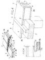
- Figure 1 shows a diagrammatic perspective view of a hollow slab portion and of a sawing machine with two cutting disks used to carry out the butting end cuts, the said sawing disks being arranged with their axes of rotation normal to one another;
- Figure 2 shows a perspective view of a hollow slab according to the present invention provided with end "chair" shoulders for bearing onto a precast beam with no lower protrusions;
- Figure 3 shows a perspective view of a hollow slab that is similar to that shown in Fig. 2 with an end "chair" shoulder obtained by using a cutting wire;
- Figure 4 is a partial perspective view of a support pillar for a horizontally resting upturned T-beam for bearing the butted ends of two abutting hollow slabs without solution of continuity both at lower and upper surfaces of the floor formed by the slabs;
- Figure 5 shows a diagrammatic perspective view of two hollow slabs having "dovetail" shaped end butts for resting onto a horizontal steel girder; and
- Figure 6 shows a detail of Fig. 5 on an enlarged scale of a "dovetail shaped" butted end of a hollow slab or girder on a steel lattice beam provided with a fireproof coating and flush with the lower surface.
-
- In the various Figures of the drawings the same or similar components are indicated by the same reference numerals.
- With reference first to Figures 1 to 4, it will be noted that a hollow pre-compressed concrete slab 1 has a number of
inner cavities 2 that extend longitudinally and parallel to the slab between anupper slab 3 and alower slab 4 thereof and having in the shown Example, an elongated light in the sense of the height of the slab. - Each slab 1 is provided with a respective "chair" shoulder or upturned
step 5 that is formed on the same side as itslower surface 4 and obtained by two butting cuts made along two inclined cutting planes (e.g. typically at a 90° angle): one of which is perpendicular to, and the other is parallel with the lying planes of theupper surface 3 andlower surface 4 of the slab. The height of theshoulders 5 can range from a few centimetres to 25 cm or more, whereas their depth can even be smaller than their height. - As known in the art, a hollow slab made of standard or pre-compressed concrete is prevailingly obtained according to two production methods. Production is carried out in factory on steel tracks typically 120-150 cm long , onto which a predetermined number of continuous reinforcements or steel pre-compression rods are suitably distributed throughout the width of the track, and jacktensioned by means of suitable jacktensioning devices designed to systematically control the rod tension and lengthening .
- Continuous casting of concrete is then carried out onto the steel track on which reinforcements and/or the steel pre-compression rods have been suitably arranged and tensioned. In order to form the concrete casting a vibratory finishing method is adopted involving the use of one or more suitable vibratory finishing machines through which concrete is fed into moving sections and hypervibrated by means of banks of vibrators operating at different vibration frequencies.
- Usually, concrete casting is carried out in one or two subsequent or simultaneous steps, i.e. for forming the
lower surface 4 of the slab, theribs 6 betweenadjacent cavities 2 and theupper surface 3 of the slab. - Concrete casting can also be carried out according to an extrusion method in which use is made of at least one forming machine into which concrete is forced, e.g. by means of metering screws, to become compacted to obtain a finished slab cross-section in one step.
- Very high quality concretes are needed, consistent in so far as both their granulometry and cement and water dosing are concerned in order to guarantee first of all prompt shape stability for obtaining
cavities 2, and high initial mechanical strength, whereby allowing pre-compression and formwork removal, when required, to be carried out in short time intervals and optimum adherence to the reinforcements (comprising, as it is known, pre-stressed rods and possible loose reinforcements provided in the casting) to be obtained. - Immediately after casting, while the concrete is still fresh, notches and/or openings are formed according to design, for locating possible vertical ducts .
- After forming, the cast concrete is left to rest for setting and hardening, so that a compact article is obtained. In order to obtain an accelerated setting or hardening, the casting is usually covered with waterproof sheets throughout its length and heated up homogeneously until the concrete has reached a required strength for the pre-stressed reinforcements to be released, and subsequently for formwork removal. Resistance is experimentally determined by breaking samples subjected to the same vibrating and thermal treatment. In general, when the concrete is subjected to a compression test at the twenty-eighth day, its cubic strength should be greater than 55 Mpa.
- In the most common case of hollow slabs, a routine strength control is carried out on the concrete, as known by the skilled person in the art, before releasing the tensioned rods and thus before pre-compressing the hardened article.
- Once the hardening has been completed, the article is cross-cut by abrasive or diamond disks 10, 11 into specified lengths for article sections designed to form a floor whereby separating the various elements or hollow slabs 1. Then, after each slab 1 has been transferred onto a testing and processing bench, two "chair" shaped
shoulders 5 are cut by carrying out two cuts at 90° one with respect to the other at the leading and trailing ends of each slab 1 (see Fig. 1), e.g. by using a butting machine (e.g. of any known type) provided with two cutting disks 10 and 11 arranged to rotate about rotation axes 10' and 11' normal to, or otherwise inclined one with respect to the other . In this way, according to the present invention, hollow slabs 1 having a T-shaped or L-shaped longitudinal section are obtained for making floors with upper and lower flat surfaces with no continuity solution at the upturned T or L shaped load resisting girders 7 ( Fig. 4). - Figure 3 shows an alternative method of obtaining end "chair"-
shaped shoulders 5, i.e. through wire cutting by means of cuttingwire 9 instead of disks 10, 11, to obtain in general "chair" shapedend shoulders 5 having rounded corners and edges. - When required by design calculation, during construction, suitable reinforcements may be provided and positioned at the ends to be cut for obtaining a "chair" support. Said reinforcements can comprise stirrups inserted into the longitudinal partition walls between the
cavities 2 before casting by means of a forming machine or else manually inserted and embedded in the cavities, or alternatively, immediately after forming, when the concrete is still fresh, or else immediately after setting when the concrete is still fresh, or after hardening and formwork removal from the hollow slab, before the manufactured article is delivered to the building site. - When the formwork is removed, the hollow slabs 1 are provided with a smooth lower surface in contact with a metal formwork (track) and rough sides and upper surface so that when the slabs are laid in position side-by-side, concrete joints cast between adjacent slabs become effectively integral with the slabs..
- Figures 5 and 6 show hollow slabs provided with "dovetail"
end shoulders 5a, i.e. having support delimiting walls that are mutually inclined at an angle smaller than 90° for use withsteel lattice beams 8, preferably provided with a fire-proof coating on their lower surface. The "dove-tail" cut ensures a better adherence of the coating 8a undermetal plate 8; such a coating preferably comprising an insulating and fireproof mortar. - As better shown in Figures 4 and 5, a hollow slab 1 according to the present invention can be used for obtaining a floor supported by both precast reinforced concrete load
resistant beams 7 andsteel lattice girders 8 or by well known semi-precast beams provided with protruding stirrups (not shown in the drawings) that need to be completed by casting onsite, e.g.steel lattice girders 8. - The invention as described above is susceptible to several modifications and variations within the protection scope as defined by the claims.
- The disclosure of Italian patent application no. VR2001A000067 from which priority date of 15 June 2001 is claimed, is incorporated herein by reference.
Claims (16)
- Method of producing a precast hollow slab or beam member made of standard or pre-compressed concrete comprising the following steps in sequence:and characterised in that it comprisescontinuous casting by means of at least one forming machine on a steel track on which suitably arranged pre-compression rods have already been laid and tensioned,setting and hardening of the casting, thereby obtaining a compact article,releasing said tensioned compression rods and consequent compression of the article,carrying out two mutually inclined cuts at least at one end of said article .
- Method as claimed in Claim 1, characterised in that it comprises cross-cutting the said article into sections of beam members or hollow slabs before slabs before obtaining the said two inclined cuts.
- Method as claimed in Claim 2, characterised in that said two inclined cuts are made at at least one or more intermediate position of the length of the said article .
- Method as claimed in Claim 3, characterised in that the said butting inclined cuts are carried out simultaneously.
- Method as claimed in any preceding Claim, characterised in that the said inclined cuts extend one heightwise and the other lengthwise with respect to a respective slab or beam, with a penetration depth which is different from one cut to another.
- Method as claimed in any preceding claim 2 to 5, characterised in that after having been cross-cut, each slab is transferred onto a laying bench in order to carry out said inclined cuts.
- Method as claimed in any preceding claim, characterised in that the said inclined cuts are carried out by means of a butting machine having two disks rotating about axes of rotation which are inclined to one another.
- Method as claimed in any claim 1 to 6, characterised in that the said inclined cuts are carried out by a cutting wire.
- Method as claimed in claim 8, characterised in that the said cutting wire is driven by moving pulleys controlled so as to follow the profile of the cut.
- Method as claimed in any preceding claim, characterised in that the said inclined cuts are mutually inclined at substantially 90°.
- Method as claimed in claim 8 or 9, characterised in that the said inclined cuts are carried out in such a way as to obtain profiles having rounded corners and edges.
- Method as claimed in any preceding claim, characterised in that it comprises inserting reinforcements into a portion of the article to be obtained or already obtained close to the portion where said inclined cuts are to be made.
- Method as claimed in Claim 11, characterised in that said reinforcements comprise stirrups or the like.
- Hollow slab having a T-shaped longitudinal section when obtained by the method according to any preceding claim.
- Hollow slab having an L-shaped longitudinal section when obtained by the method as claimed in any claim 1 to 13.
- Precast beam member when obtained by the method as claimed in any claim 1 to 13.
Applications Claiming Priority (2)
| Application Number | Priority Date | Filing Date | Title |
|---|---|---|---|
| IT2001VR000067A ITVR20010067A1 (en) | 2001-06-15 | 2001-06-15 | PROCEDURE TO PRODUCE A PRECOMPRESSED CONCRETE ALVEOLAR SHEET AND SO OBTAINED |
| ITVR20010067 | 2001-06-15 |
Publications (3)
| Publication Number | Publication Date |
|---|---|
| EP1266735A2 true EP1266735A2 (en) | 2002-12-18 |
| EP1266735A3 EP1266735A3 (en) | 2004-03-10 |
| EP1266735B1 EP1266735B1 (en) | 2007-12-19 |
Family
ID=11462044
Family Applications (1)
| Application Number | Title | Priority Date | Filing Date |
|---|---|---|---|
| EP02012483A Expired - Lifetime EP1266735B1 (en) | 2001-06-15 | 2002-06-12 | Method of producing a precast slab or beam made of standard or precompressed concrete |
Country Status (5)
| Country | Link |
|---|---|
| EP (1) | EP1266735B1 (en) |
| AT (1) | ATE381419T1 (en) |
| DE (1) | DE60224133D1 (en) |
| ES (1) | ES2296843T3 (en) |
| IT (1) | ITVR20010067A1 (en) |
Families Citing this family (2)
| Publication number | Priority date | Publication date | Assignee | Title |
|---|---|---|---|---|
| ES2483190B1 (en) * | 2013-02-05 | 2015-05-11 | Prefabricados Pujol, S.A. | Manufacturing procedure for concrete parts and concrete piece thus obtained |
| CN109356043A (en) * | 2018-11-21 | 2019-02-19 | 南京铁道职业技术学院 | Existing hollow slab girder single slab bearing reinforcing construction and reinforcement means |
Citations (2)
| Publication number | Priority date | Publication date | Assignee | Title |
|---|---|---|---|---|
| DE577519C (en) * | 1931-10-09 | 1933-06-01 | Carl Ludowici Falzziegelwerke | Process for the production of building structures, in particular those made of clay |
| US4778371A (en) * | 1986-01-17 | 1988-10-18 | Kt-Suunnittelu Oy | Apparatus for forming frogs in the sides of a concrete element |
-
2001
- 2001-06-15 IT IT2001VR000067A patent/ITVR20010067A1/en unknown
-
2002
- 2002-06-12 DE DE60224133T patent/DE60224133D1/en not_active Expired - Lifetime
- 2002-06-12 EP EP02012483A patent/EP1266735B1/en not_active Expired - Lifetime
- 2002-06-12 ES ES02012483T patent/ES2296843T3/en not_active Expired - Lifetime
- 2002-06-12 AT AT02012483T patent/ATE381419T1/en not_active IP Right Cessation
Patent Citations (2)
| Publication number | Priority date | Publication date | Assignee | Title |
|---|---|---|---|---|
| DE577519C (en) * | 1931-10-09 | 1933-06-01 | Carl Ludowici Falzziegelwerke | Process for the production of building structures, in particular those made of clay |
| US4778371A (en) * | 1986-01-17 | 1988-10-18 | Kt-Suunnittelu Oy | Apparatus for forming frogs in the sides of a concrete element |
Also Published As
| Publication number | Publication date |
|---|---|
| ES2296843T3 (en) | 2008-05-01 |
| EP1266735B1 (en) | 2007-12-19 |
| EP1266735A3 (en) | 2004-03-10 |
| DE60224133D1 (en) | 2008-01-31 |
| ITVR20010067A1 (en) | 2002-12-15 |
| ATE381419T1 (en) | 2008-01-15 |
Similar Documents
| Publication | Publication Date | Title |
|---|---|---|
| EP2021555B1 (en) | Concrete beam | |
| EP2739799B1 (en) | Building structure of pre-cast monolithic walls and interfloor slabs | |
| EP1445391B1 (en) | Assembly of prefabricated components for making floor slabs, floors and walls with exposed wood beams | |
| WO1994023143A1 (en) | Method for manufacturing concrete elements and a concrete element manufactured according to the method | |
| US5146726A (en) | Composite building system and method of manufacturing same and components therefor | |
| EP1266735B1 (en) | Method of producing a precast slab or beam made of standard or precompressed concrete | |
| US20220316210A1 (en) | Precast building panel | |
| EP0054026B1 (en) | Lost formwork for use when casting concrete floors | |
| US4831801A (en) | Process for manufacturing construction elements, their composition, reinforcement and means for mounting same | |
| GB748104A (en) | Improvements relating to building structures | |
| EP3719229A9 (en) | Concrete floor panel, method of production of such panel and floor made of this panel | |
| US20030001070A1 (en) | Manufactured reinforced concrete system | |
| RU2184816C1 (en) | Built-up-monolithic reinforced-concrete frame of many-storied building "kazan-100" | |
| JPS6151524B2 (en) | ||
| CA1202502A (en) | Arrangement for laying concrete floor | |
| AU2003203877B2 (en) | Pre-formed, post tensioned, pre-finished cement bound synthetic stone stairway | |
| AU2012247042C1 (en) | Structural Elements and Methods of Use Therefore | |
| US3855375A (en) | Floor building system | |
| EP3279408A1 (en) | Method for the reinforcement of ribbed floors with a division slab made of cast concrete and floor thus reinforced | |
| Hale et al. | Precast concrete floors | |
| JPH02140344A (en) | Joint part structure between prefabricated concrete beam and slab | |
| GB865141A (en) | Improvements in or relating to staircases of concrete and like materials | |
| JPH06248801A (en) | Manufacturing method of reinforced concrete face member | |
| HU200382B (en) | Method for producing frontal pieces and piece and method for fastening same on frontage | |
| RU2003128386A (en) | METHOD FOR ESTABLISHING INTER-FLOOR CEILINGS |
Legal Events
| Date | Code | Title | Description |
|---|---|---|---|
| PUAI | Public reference made under article 153(3) epc to a published international application that has entered the european phase |
Free format text: ORIGINAL CODE: 0009012 |
|
| AK | Designated contracting states |
Kind code of ref document: A2 Designated state(s): AT BE CH CY DE DK ES FI FR GB GR IE IT LI LU MC NL PT SE TR |
|
| AX | Request for extension of the european patent |
Free format text: AL;LT;LV;MK;RO;SI |
|
| PUAL | Search report despatched |
Free format text: ORIGINAL CODE: 0009013 |
|
| AK | Designated contracting states |
Kind code of ref document: A3 Designated state(s): AT BE CH CY DE DK ES FI FR GB GR IE IT LI LU MC NL PT SE TR |
|
| AX | Request for extension of the european patent |
Extension state: AL LT LV MK RO SI |
|
| RIC1 | Information provided on ipc code assigned before grant |
Ipc: 7B 28B 11/12 B Ipc: 7B 28B 23/06 A |
|
| 17P | Request for examination filed |
Effective date: 20040716 |
|
| AKX | Designation fees paid |
Designated state(s): AT BE CH CY DE DK ES FI FR GB GR IE IT LI LU MC NL PT SE TR |
|
| GRAP | Despatch of communication of intention to grant a patent |
Free format text: ORIGINAL CODE: EPIDOSNIGR1 |
|
| GRAS | Grant fee paid |
Free format text: ORIGINAL CODE: EPIDOSNIGR3 |
|
| RAP1 | Party data changed (applicant data changed or rights of an application transferred) |
Owner name: GRUPPO CENTRO NORD S.P.A. |
|
| GRAA | (expected) grant |
Free format text: ORIGINAL CODE: 0009210 |
|
| AK | Designated contracting states |
Kind code of ref document: B1 Designated state(s): AT BE CH CY DE DK ES FI FR GB GR IE IT LI LU MC NL PT SE TR |
|
| REG | Reference to a national code |
Ref country code: GB Ref legal event code: FG4D |
|
| REG | Reference to a national code |
Ref country code: IE Ref legal event code: FG4D |
|
| REG | Reference to a national code |
Ref country code: CH Ref legal event code: EP |
|
| REF | Corresponds to: |
Ref document number: 60224133 Country of ref document: DE Date of ref document: 20080131 Kind code of ref document: P |
|
| PG25 | Lapsed in a contracting state [announced via postgrant information from national office to epo] |
Ref country code: LI Free format text: LAPSE BECAUSE OF FAILURE TO SUBMIT A TRANSLATION OF THE DESCRIPTION OR TO PAY THE FEE WITHIN THE PRESCRIBED TIME-LIMIT Effective date: 20071219 Ref country code: SE Free format text: LAPSE BECAUSE OF FAILURE TO SUBMIT A TRANSLATION OF THE DESCRIPTION OR TO PAY THE FEE WITHIN THE PRESCRIBED TIME-LIMIT Effective date: 20080319 Ref country code: CH Free format text: LAPSE BECAUSE OF FAILURE TO SUBMIT A TRANSLATION OF THE DESCRIPTION OR TO PAY THE FEE WITHIN THE PRESCRIBED TIME-LIMIT Effective date: 20071219 |
|
| REG | Reference to a national code |
Ref country code: ES Ref legal event code: FG2A Ref document number: 2296843 Country of ref document: ES Kind code of ref document: T3 |
|
| PG25 | Lapsed in a contracting state [announced via postgrant information from national office to epo] |
Ref country code: FI Free format text: LAPSE BECAUSE OF FAILURE TO SUBMIT A TRANSLATION OF THE DESCRIPTION OR TO PAY THE FEE WITHIN THE PRESCRIBED TIME-LIMIT Effective date: 20071219 |
|
| REG | Reference to a national code |
Ref country code: CH Ref legal event code: PL |
|
| PG25 | Lapsed in a contracting state [announced via postgrant information from national office to epo] |
Ref country code: AT Free format text: LAPSE BECAUSE OF FAILURE TO SUBMIT A TRANSLATION OF THE DESCRIPTION OR TO PAY THE FEE WITHIN THE PRESCRIBED TIME-LIMIT Effective date: 20071219 |
|
| ET | Fr: translation filed | ||
| PG25 | Lapsed in a contracting state [announced via postgrant information from national office to epo] |
Ref country code: PT Free format text: LAPSE BECAUSE OF FAILURE TO SUBMIT A TRANSLATION OF THE DESCRIPTION OR TO PAY THE FEE WITHIN THE PRESCRIBED TIME-LIMIT Effective date: 20080519 |
|
| PGFP | Annual fee paid to national office [announced via postgrant information from national office to epo] |
Ref country code: BE Payment date: 20080630 Year of fee payment: 7 |
|
| PLBE | No opposition filed within time limit |
Free format text: ORIGINAL CODE: 0009261 |
|
| STAA | Information on the status of an ep patent application or granted ep patent |
Free format text: STATUS: NO OPPOSITION FILED WITHIN TIME LIMIT |
|
| PG25 | Lapsed in a contracting state [announced via postgrant information from national office to epo] |
Ref country code: DK Free format text: LAPSE BECAUSE OF FAILURE TO SUBMIT A TRANSLATION OF THE DESCRIPTION OR TO PAY THE FEE WITHIN THE PRESCRIBED TIME-LIMIT Effective date: 20071219 Ref country code: DE Free format text: LAPSE BECAUSE OF FAILURE TO SUBMIT A TRANSLATION OF THE DESCRIPTION OR TO PAY THE FEE WITHIN THE PRESCRIBED TIME-LIMIT Effective date: 20080320 |
|
| PGFP | Annual fee paid to national office [announced via postgrant information from national office to epo] |
Ref country code: NL Payment date: 20080630 Year of fee payment: 7 |
|
| 26N | No opposition filed |
Effective date: 20080922 |
|
| PGFP | Annual fee paid to national office [announced via postgrant information from national office to epo] |
Ref country code: FR Payment date: 20080627 Year of fee payment: 7 |
|
| PG25 | Lapsed in a contracting state [announced via postgrant information from national office to epo] |
Ref country code: GR Free format text: LAPSE BECAUSE OF FAILURE TO SUBMIT A TRANSLATION OF THE DESCRIPTION OR TO PAY THE FEE WITHIN THE PRESCRIBED TIME-LIMIT Effective date: 20080320 Ref country code: MC Free format text: LAPSE BECAUSE OF NON-PAYMENT OF DUE FEES Effective date: 20080630 |
|
| GBPC | Gb: european patent ceased through non-payment of renewal fee |
Effective date: 20080612 |
|
| PG25 | Lapsed in a contracting state [announced via postgrant information from national office to epo] |
Ref country code: IE Free format text: LAPSE BECAUSE OF NON-PAYMENT OF DUE FEES Effective date: 20080612 |
|
| PG25 | Lapsed in a contracting state [announced via postgrant information from national office to epo] |
Ref country code: GB Free format text: LAPSE BECAUSE OF NON-PAYMENT OF DUE FEES Effective date: 20080612 |
|
| PG25 | Lapsed in a contracting state [announced via postgrant information from national office to epo] |
Ref country code: CY Free format text: LAPSE BECAUSE OF FAILURE TO SUBMIT A TRANSLATION OF THE DESCRIPTION OR TO PAY THE FEE WITHIN THE PRESCRIBED TIME-LIMIT Effective date: 20071219 |
|
| BERE | Be: lapsed |
Owner name: GRUPPO CENTRO NORD S.P.A. Effective date: 20090630 |
|
| NLV4 | Nl: lapsed or anulled due to non-payment of the annual fee |
Effective date: 20100101 |
|
| REG | Reference to a national code |
Ref country code: FR Ref legal event code: ST Effective date: 20100226 |
|
| PG25 | Lapsed in a contracting state [announced via postgrant information from national office to epo] |
Ref country code: FR Free format text: LAPSE BECAUSE OF NON-PAYMENT OF DUE FEES Effective date: 20090630 |
|
| PG25 | Lapsed in a contracting state [announced via postgrant information from national office to epo] |
Ref country code: BE Free format text: LAPSE BECAUSE OF NON-PAYMENT OF DUE FEES Effective date: 20090630 |
|
| PG25 | Lapsed in a contracting state [announced via postgrant information from national office to epo] |
Ref country code: NL Free format text: LAPSE BECAUSE OF NON-PAYMENT OF DUE FEES Effective date: 20100101 Ref country code: LU Free format text: LAPSE BECAUSE OF NON-PAYMENT OF DUE FEES Effective date: 20080612 |
|
| PG25 | Lapsed in a contracting state [announced via postgrant information from national office to epo] |
Ref country code: TR Free format text: LAPSE BECAUSE OF FAILURE TO SUBMIT A TRANSLATION OF THE DESCRIPTION OR TO PAY THE FEE WITHIN THE PRESCRIBED TIME-LIMIT Effective date: 20071219 |
|
| PGFP | Annual fee paid to national office [announced via postgrant information from national office to epo] |
Ref country code: IT Payment date: 20110627 Year of fee payment: 10 |
|
| PGFP | Annual fee paid to national office [announced via postgrant information from national office to epo] |
Ref country code: ES Payment date: 20110706 Year of fee payment: 10 |
|
| PG25 | Lapsed in a contracting state [announced via postgrant information from national office to epo] |
Ref country code: IT Free format text: LAPSE BECAUSE OF NON-PAYMENT OF DUE FEES Effective date: 20120612 |
|
| REG | Reference to a national code |
Ref country code: ES Ref legal event code: FD2A Effective date: 20131021 |
|
| PG25 | Lapsed in a contracting state [announced via postgrant information from national office to epo] |
Ref country code: ES Free format text: LAPSE BECAUSE OF NON-PAYMENT OF DUE FEES Effective date: 20120613 |