EP1265422A1 - Portable radio terminal and sound delivery method and sound intake method - Google Patents
Portable radio terminal and sound delivery method and sound intake method Download PDFInfo
- Publication number
- EP1265422A1 EP1265422A1 EP02711298A EP02711298A EP1265422A1 EP 1265422 A1 EP1265422 A1 EP 1265422A1 EP 02711298 A EP02711298 A EP 02711298A EP 02711298 A EP02711298 A EP 02711298A EP 1265422 A1 EP1265422 A1 EP 1265422A1
- Authority
- EP
- European Patent Office
- Prior art keywords
- signal
- earphones
- voice
- main body
- microphone
- Prior art date
- Legal status (The legal status is an assumption and is not a legal conclusion. Google has not performed a legal analysis and makes no representation as to the accuracy of the status listed.)
- Withdrawn
Links
Images


Classifications
-
- H—ELECTRICITY
- H04—ELECTRIC COMMUNICATION TECHNIQUE
- H04M—TELEPHONIC COMMUNICATION
- H04M1/00—Substation equipment, e.g. for use by subscribers
- H04M1/60—Substation equipment, e.g. for use by subscribers including speech amplifiers
- H04M1/6033—Substation equipment, e.g. for use by subscribers including speech amplifiers for providing handsfree use or a loudspeaker mode in telephone sets
- H04M1/6041—Portable telephones adapted for handsfree use
- H04M1/6058—Portable telephones adapted for handsfree use involving the use of a headset accessory device connected to the portable telephone
-
- H—ELECTRICITY
- H04—ELECTRIC COMMUNICATION TECHNIQUE
- H04B—TRANSMISSION
- H04B1/00—Details of transmission systems, not covered by a single one of groups H04B3/00 - H04B13/00; Details of transmission systems not characterised by the medium used for transmission
- H04B1/38—Transceivers, i.e. devices in which transmitter and receiver form a structural unit and in which at least one part is used for functions of transmitting and receiving
- H04B1/40—Circuits
-
- H—ELECTRICITY
- H04—ELECTRIC COMMUNICATION TECHNIQUE
- H04M—TELEPHONIC COMMUNICATION
- H04M1/00—Substation equipment, e.g. for use by subscribers
- H04M1/72—Mobile telephones; Cordless telephones, i.e. devices for establishing wireless links to base stations without route selection
- H04M1/724—User interfaces specially adapted for cordless or mobile telephones
- H04M1/72403—User interfaces specially adapted for cordless or mobile telephones with means for local support of applications that increase the functionality
- H04M1/7243—User interfaces specially adapted for cordless or mobile telephones with means for local support of applications that increase the functionality with interactive means for internal management of messages
-
- H—ELECTRICITY
- H04—ELECTRIC COMMUNICATION TECHNIQUE
- H04M—TELEPHONIC COMMUNICATION
- H04M2250/00—Details of telephonic subscriber devices
- H04M2250/02—Details of telephonic subscriber devices including a Bluetooth® interface
Definitions
- This invention relates to a portable wireless terminal, a method of outputting sound and a method of picking up sound, and is suitably applied, for example, to a digital mobile phone having a music data reproducing function.
- earphones are used to reproduce music data.
- the music data is reproduced from the memory in the state where a plug connected to the above earphones is inserted into an earphone jack provided on the digital mobile phone.
- the above reproduced music data is converted into an analog audio signal and transmitted to the earphones from the earphone jack via the plug.
- music based on the audio signal is emitted from the above earphones.
- the digital mobile phone informs the user of the call incoming by superimposing a signal for ringing tone on the audio signal corresponding to the above music data and transmitting them to the earphones, and ringing an incoming tone from the earphones along with music.
- the digital mobile phone can make the user speak over the phone with the other party by informing the user of the call incoming.
- the earphone jack is a mechanical switch. If the earphones plug is inserted into the above earphone jack, only the earphones are forcedly made to work instead of a speaker provided on the digital mobile phone.
- This invention has been done considering the above points and is proposing a portable wireless terminal, a method of outputting sound and a method of picking out sound in that the usability can be improved.
- a speaker for emitting a sound based on a predetermined audio signal, an earphone jack to insert so as to be able to pull out, a plug connected to earphones for emitting the sound based on the audio signal, signal output means for outputting the audio signal to the speaker or outputting the audio signal from the earphone jack to the earphones via the plug, and control means for controlling the signal output means to output the arbitrary audio signal or another audio signal to the specified speaker and/or earphones at arbitrary timing when in transmitting the arbitrary audio signal to the speaker and/or the earphones, are provided.
- the audio signal when an audio signal is being outputted to the speaker and/or the earphones, the audio signal can be outputted to the arbitrary selected desired speaker and/or earphones by switching the signal output means to them without pulling the plug out of the earphone jack.
- a main body microphone for picking up user's voice for call an earphone jack to insert so as to be able to pull out
- signal fetch means for fetching send voice signal obtained by picking up the user's voice by the main body microphone, or fetching send voice signal obtained by picking up the user's voice by the earphones and control means for controlling the signal fetch means to fetch the send voice signal obtained by picking up the user's voice by the arbitrary main body microphone and/or external microphone when the plug is inserted into the earphone jack, are provided.
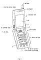
- Fig. 1 is a schematic perspective view showing one embodiment of the external structure of a digital mobile phone according to this invention.
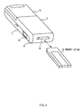
- Fig. 2 is a schematic perspective view showing the structure of the back of the main body of the digital mobile phone.
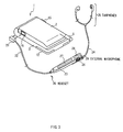
- Fig. 3 is a schematic perspective view showing the structure of a headset.
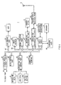
- Fig. 4 is a block diagram showing the circuitry of the digital mobile phone.
- Fig. 5 is a flowchart showing the input-output switching processing procedure of a voice signal.
- a reference numeral 1 generally shows a digital mobile phone adopting the present invention.
- a display part 2 and a main body 3 are foldable via a hinge part 4.
- an antenna 5 for send/receive is provided so as to be pulled out/housed. Radio waves can be transmitted/received from a base station (not shown) via the above antenna 5.
- a speaker 6 is provided.
- the voice of the other party on calling can be emitted by the above speaker 6.
- a liquid crystal display (LCD) 7 is provided at the lower part than the speaker 6.
- LCD 7 the name or the mail address of the destination of an electronic mail registered as a mail address, the contents of an electronic mail, a simple homepage, an web page, etc. can be displayed in addition to the receiving state of radio waves, the residual amount of battery, the name or the telephone number of the other party registered as a telephone directory, originated history, etc.
- operation keys 8 such as numeric keys of "0" to "9", a call originating key, a redial key, an on-hook/power key, a clear key, an electronic mail key are disposed.
- the user can enter various commands by means of the above operation keys 8.
- a memo button 9 and a microphone (hereinafter, this is referred to as main body microphone) 10 are provided at the lower part than the operation keys 8.
- the voice of the other party on calling can be recorded by the above memo button 9, and user's voice on calling is picked up by the main body microphone 10.
- a rotary controller (hereinafter, this is referred to as jog dial) 11 that is freely turnable and can be freely depressed is provided in slightly projecting from the front surface of the main body 3.
- Scroll operation of the list of telephone directory or mail address, the contents of an electronic mail, etc., displayed on the LCD 7, turn over operation of a simple homepage or an web page, etc. will be executed according to the turning operation of the above jog dial 11, and a desired telephone number or mail address can be selectively specified from the list of the telephone directory or the mail address according to the depressing operation of the jog dial 11.
- a battery pack 12 which is freely detachable is mounted on the back surface of the main body 3. If the portable wireless terminal 1 becomes into on state according to the depression of the on-hook/power key, power is supplied to each internal circuit from the above battery pack 12, and the portable wireless terminal 1 is activated into operable state.
- a memory stick slot 14 to load a memory stick (trademark by SONY Corporation) 13 into the main body 3 in freely ejectable is provided on the hinge part 4. If the memo button 9 is depressed, the voice of the other party on calling can be recorded in the memory stick 13, or various data such as an electronic mail, a simple homepage, music data can be recorded/reproduced according to user's operation.
- the memory stick 13 is a kind of flash memory card developed by the present applicant, SONY corporation.
- This memory stick 13 stores a flash memory device being a kind of electrically erasable and programmable read only memory (EEPROM) that is a nonvolatile memory electrically rewritable and erasable, in a small and thin plastic case for example 21.5 [mm] in length, 50 [mm] in width and 2.8 [mm] in thickness. It is writable and readable various data such as pictures, voice, music, via a 10-pin terminal.
- EEPROM electrically erasable and programmable read only memory
- the memory stick 13 adopts original serial protocol that can maintain compatibility between using devices, also against the change of specification of internal flash memory owing to becoming to bulk storage. For instance, it realizes high speed performance of the maximum write speed 1.5 [MB/s], the maximum read speed 2.45 [MB/s] as well as maintaining high reliability by providing an erroneous deletion prevention switch.
- the digital mobile phone 1 also can load the memory stick 13 in that music data has been previously recorded by external audio equipment (not shown). But since a connection terminal 15 to connect with external audio equipment or the like is provided on the right side of the display part 2 as shown in Fig. 1, so that also music data obtained from the external audio equipment via the connection terminal 15 can be recorded in the memory stick 13 in the memory stick slot 14.
- an earphone jack 16 is provided on the left side surface of the display part 2.
- the plug 21 of a headset 20 that can be freely pulled out shown in Fig. 3 can be inserted into the above earphone jack 16.
- a remote control 23 is connected to the plug 21 via a cable (hereinafter, this is referred to as plug side cable) 22, and the earphones 25 is connected to the above remote control 23 via a cable (hereinafter, this is referred to as earphone side cable) 24.
- a music data play/stop button 26 On the remote control 23 of the headset 20, a music data play/stop button 26, an LCD part 27 to display the title of music on reproducing, an on-hook/off-hook button 28, a microphone (hereinafter, this is referred to as external microphone) 29, etc. are provided.
- the plug 21 of the headset 20 when the plug 21 of the headset 20 is not inserted into the earphone jack 16, the user can talk by the telephone by means of the above speaker 6 and main body microphone 10 by working them.
- the digital mobile phone 1 works the earphones 25 and the external microphone 29 of the headset 20 instead of the speaker 6 and the main body microphone 10.
- the digital mobile phone 1 reproduces music data from the memory stick 13, converts the above reproduced music data into an audio signal and transmitting this to the earphones 25 from the earphone jack 16 sequentially via the plug 21, the plug side cable 22, the remote control 23 and the earphone side cable 24. Thereby, music based on the audio signal is emitted from the above earphones 25.
- the digital mobile phone 1 also reproduces digital additional data formed by the title of the music etc., recorded along with the music data, from the memory stick 13.
- the above additional data reproduced is converted into an analog additional signal, and the signal is transmitted to the remote control 23 from the earphone jack 16 sequentially via the plug 21 and the plug side cable 22.
- the title of the music on reproducing or the like is displayed on the LCD part 27 of the above remote control 23 based on that additional signal.
- the digital mobile phone 1 superimposes a signal for incoming tone on the audio signal based on that music data and transmitting them to the earphones 25 of the headset 20, and informing the user of the call incoming by emitting an incoming tone along with the music from the above earphones 25.
- the digital mobile phone 1 temporarily stops reproducing the music data, converts the voice data of the other party received at this time into a voice signal (hereinafter, this is referred to as receive voice signal), and transmits this to the earphones 25 from the earphone jack 16 sequentially via the plug 21, the plug side cable 22, the remote control 23 and the earphone side cable 24.
- receive voice signal a voice signal
- the voice of the other party based on that receive voice signal is emitted from the above earphones 25.
- the digital mobile phone 1 picks up user's voice by the external microphone 29 on the remote control 23, takes in thus obtained voice signal (hereinafter, this is referred to as send voice signal) from the earphone jack 16 sequentially via the plug side cable 22 and the plug 21 and transmitting that send voice signal from the antenna 5 to the base station.
- send voice signal a voice signal from the earphone jack 16 sequentially via the plug side cable 22 and the plug 21 and transmitting that send voice signal from the antenna 5 to the base station.
- the digital mobile phone 1 enables a call between the user and the other party by means of the earphones 25 of the headset 20 and the external microphone 29 even if music data is being reproduced.
- the digital mobile phone 1 does not accept the depressing operation of the play/stop button 26 on the remote control 23. If the on-hook/off-hook button 28 on the above remote control 23 is depressed again and the call with the other party has finished, the digital mobile phone 1 accepts the depressing operation of the play/stop button 26 on the remote control 23.
- the digital mobile phone 1 reproduces the music data from the position where reproduction has stopped when the call started to make the user listen to the music again.
- a switch button 30 being a toggle switch to work either of the earphones 25 and the external microphone 29 of the headset 20 or the speaker 6 and the main body microphone 10 is provided for the input/output of voice signals for call (send voice signal and receive voice signal).
- the digital mobile phone 1 works only the speaker 6 and the main body microphone 10 and does not accept the depressing operation of the switch 30. Thereby, that the input/output of the voice signals (send voice signal and receive voice signal) are switched into the headset 20 by the depressing operation of the switch button 30 on the calling with the speaker 6 and the main body microphone 10 and the call is disconnected is prevented.
- the digital mobile phone 1 does not accept the depressing operation of the switch button 30 while music data is being reproduced even if the plug 21 of the headset 20 is inserted into the earphone jack 16, it prevents that the music being listened with the earphones 25 is interrupted by switching into the speaker 6 by the depressing operation of the switch button 30.
- the digital mobile phone 1 accepts the depressing operation of the switch button 30. So that, the earphones 25 and the external microphone 29 of the headset 20 or the speaker 6 and the main body microphone 10 alternately work by sequentially switched every time when the above switch button 30 is depressed.
- this digital mobile phone 1 works the speaker 6 and the main body microphone 10 instead of the above earphones 25 and external microphone 29 of the headset 20.
- the user holds the main body 3 and puts the speaker 6 his/her ear, and the user can talk by the telephone with the other party in the state where the main body microphone 10 is positioned near his/her mouse.
- the digital mobile phone 1 works the speaker 6 and the main body microphone 10 in the state where the plug 21 of the headset 20 is inserted into the earphone jack 16 in the calling mode
- the digital mobile phone 1 works the earphones 25 and the external microphone 29 instead of the above speaker 6 and main body microphone 10 according to the depressing operation of the switch button 30. So that, the user can talk by the telephone with the headset 20.
- the earphones 25 and the external microphone 29 of the headset 20 can be easily switched to the speaker 6 and the main body microphone 10 and used by a simple operation only by depressing the switch button 30.
- the digital mobile phone 1 automatically works the earphones 25 and the external microphone 29 instead of the speaker 6 and the main body microphone 10 at a time point where the above call finished.
- the user can listen to the music via the headset 20 without performing switching operation from the speaker 6 and the main body microphone 10 to the earphones 25 and the external microphone 29.
- the digital mobile phone 1 can accurately inform the user of this.
- the digital mobile phone 1 enables the call between the user and the other party not only by the depressing operation of the on-hook/off-hook button 28 on the remote control 23 but also by the depressing operation of the call originating key on the main body 3.
- the digital mobile phone 1 accepts the depressing operation of both of the on-hook/off-hook button 28 on the remote control 23 of the headset 20 and the on-hook/power key on the main body 3, and disconnecting the call. Thus, lacking the operability is prevented.
- a power supply circuit part 42, an operation input control part 43, a connection terminal 15, a liquid crystal display (LCD) control part 44, an image decoder 45, a demultiplexing part 46, a recording/reproducing part 47, a modulation demodulation circuit part 48 and an audio CODEC 49 are connected to a main control part 40 that integratively controls each part of the display part 2 and the main body 3 via a main bus 41, and the image decoder 45, the demultiplexing part 46, the recording/reproducing part 47, the modulation demodulation circuit 48 and the audio CODEC 49 are mutually connected via a synchronous bus 50.
- the main control part 40 is composed of a central processing unit (CPU), a read only memory (ROM), a random access memory (RAM), etc. If an on command is entered via the operation input control part 43 by the user's depression of the on-hook/power key, power obtained from the battery pack 12 (Fig. 2) is supplied to each part via the power supply circuit part 42. Thus, the digital mobile phone 1 is started into operable state.
- CPU central processing unit
- ROM read only memory
- RAM random access memory
- the main control part 40 convert a send voice signal obtained by picking up user's voice by the main body microphone 10 into voice data by the audio CODEC 49.
- the main control part 40 subjects the voice data obtained by the audio CODEC 49 to spread spectrum processing in the modulation demodulation circuit 48, and then sequentially subjects it to digital-to-analog conversion processing and frequency modulation processing in a transmitter-receiver part 51, and transmitting thus obtained sending signal for send voice signal to the base station (not shown) via the antenna 5.
- the main control part 40 amplifies a received signal for receive voice signal that was received by the antenna 5 in the calling mode in the transmitter-receiver part 51, sequentially subjects it to frequency modulation processing and analog-to-digital conversion processing, and then subjects it to back-spread spectrum in the modulation demodulation circuit part 48, converts thus obtained voice data into a receive voice signal by the audio CODEC 49 and transmitting this to the speaker 6, and emitting the voice of the other party based on the receive voice signal from the above speaker 6.
- the main control part 40 subjects the text data of the electronic mail entered via the operation input control part 43 according to the operation of the operation keys 8 and the jog dial 11 to spread spectrum processing by the modulation demodulation circuit part 99, and then sequentially subjects it to digital-to-analog conversion processing and frequency modulation processing by the transmitter-receiver part 51, and transmits thus obtained sending signal for electronic mail to the base station via the antenna 5.
- the main control part 40 When in receiving an electronic mail in the data communication mode, the main control part 40 amplifies the received signal for electronic mail received by the antenna 5 by the transmitter-receiver part 51, sequentially subjects it to frequency modulation processing and analog-to-digital conversion processing, and then subjects it to back-spread spectrum processing by the modulation demodulation circuit part 48 and restoring to the original text data.
- the main control part 40 outputs the restored text data to the LCD 7 via the LCD control part 44 to display the electronic mail of the other party based on that text data on the above LCD.
- the main control part 40 can record the received electronic mail in the memory stick 13 via the recording/reproducing part 47 according to user's operation.
- the main control part 40 When in receiving for example a simple home page in the data communication mode, the main control part 40 amplifies the received signal for simple home page received by the antenna 5 by the transmitter-receiver part 51, sequentially subjects it to frequency modulation processing and analog-to-digital conversion processing, and then subjects it to spread spectrum processing by the modulation demodulation circuit part 48 and transmitting thus obtained multiplex data to the demultiplexing part 46.
- the main control part 40 separates that multiplex data into coded picture data and audio data by the demultiplexing part 46, and transmits the above coded picture data to the image decoder 45 via the synchronous bus 50 as well as transmitting the audio data to the audio CODEC 49 via the synchronous bus 50.
- the main control part 40 decodes that coded picture data by the image decoder 45 by a decoding system corresponding to the specified coding system, and transmits thus obtained picture data to the LCD 7 via the LCD control part 44 to display the picture of the simple home page based on that picture data on the above LCD 7.
- the main control part 40 converts the audio data into an audio signal by the audio CODEC 49 and outputting this to the speaker 6, and emitting an effective sound or the like of the simple home page based on that audio data from the above speaker 6 in synchronization with the above picture of the simple home page.
- the main control part 40 can record the multiplex data of the simple home page in the memory stick 13 via the recording/reproducing part 47 according to user's operation similarly to the case of receiving an electronic mail.
- the main control part 40 takes in the music data supplied from external audio equipment or the like (not shown) according to user's operation via the connection terminal 15, and records the above taken music data in the memory stick 13 via the recording/reproducing part 47.
- a contact to detect the insertion of the plug 21 by that is conducted until the plug 21 of the headset 20 is inserted and if the above plug 21 is inserted, it is opened by pushed by that plug 21 (hereinafter, this is referred to as detection contact) is provided.
- the audio CODEC 49 monitors the change of that voltage value while applying voltage of a predetermined value previously set to the detection contact in the earphone jack 16 (hereinafter, this is referred to as prescribed value).
- the audio CODEC 49 detects the voltage or the prescribed value applied to the above detection contact as it is.
- the audio CODEC 49 detects a lower value than the prescribed value (e.g. 0 [V]) as a voltage value applied to the above detection contact.
- the audio CODEC 49 decides that the plug 21 of the headset 20 is not inserted into the above earphone jack 16, and informs the main control part 40 of that decision result.
- the audio CODEC 49 decides that the plug 21 of the headset 20 was inserted into the above earphone jack 16, and informs the main control part 40 of that decision result.
- the main control part 40 recognizes whether or not the plug 21 of the headset 20 is inserted into the earphone jack 16 based on the decision result informed from the audio CODEC 49.
- a switching device (not shown) for switching which of the earphones 25 and the external microphone 29 of the headset 20, and the speaker 6 and the main body microphone 10 should be connected to output a receive voice signal and to input a send voice signal is provided.
- the main control part 40 connects the speaker 6 and the main body microphone 10 to that audio CODEC 49 by the switching device. Thereby, a call (including call incoming, the sound emitting of an effective sound of a simple home page or the like) by means of the above speaker 6 and main body microphone 10 is enabled.
- the main control part 40 connects the earphones 25 and the external microphone 29 of the headset 20 to that audio CODEC 49 by the switching device.
- the main control part 40 takes in that reproducing command from the above remote control 23 sequentially via the plug side cable 22, the plug 21, the earphone jack 16 and the audio CODEC 49, and reproduces music data from the memory stick 13 via the recording/reproducing part 47 based on the above taken reproducing command, converts the above reproduced music data into an audio signal by the audio CODEC 49 and transmitting this to the headset 20 from the earphone jack 16.
- the main control part 40 If a call comes while such reproducing of the music data, the main control part 40 superimposes a signal for call incoming on the audio signal and transmitting them to the headset 20 from the audio CODEC 49, and informing the user of the call incoming while making him/her listen to the music.
- the main control part 40 accepts the depressing operation of the switch button 30 during from the above time point that the call came until this call is finished.
- the main control part 40 connects the speaker 6 and the main body microphone 10 to the audio CODEC 49 instead of the earphones 25 and the external microphone 29 of the headset 20 by the switching device.
- the voice of the other party that was emitted from the earphones 25 is emitted from the speaker 6, and user's voice picked up via the external microphone 29 is picked up via the main body microphone 10.
- the switch button 30 is depressed again, according to this, the main control part 40 connects the earphones 25 and the external microphone 29 to the audio CODEC 49 instead of the speaker 6 and the main body microphone 10 by the switching device.
- the voice of the other party emitted from the above speaker 6 is emitted from the earphones 25 and user's voice picked up via the main body microphone 10 is picked up via the external microphone 29.
- the main control part 40 can work the earphones 25 and the external microphone 29 or the speaker 6 and the main body microphone 10 by sequentially alternately switching them every time when the switch button 30 is depressed.
- the main control part 40 finishes the call according to this.
- the main control part 40 connects the earphones 25 and the external microphone 29 to the audio CODEC 49 instead of the speaker 6 and the main body microphone 10 by the switching device.
- the main control part 40 executes such input/output switching processing of a send voice signal and a receive voice signal according to a switching processing program that has been previously stored in the internal ROM.
- the main control part 40 enters switching processing procedure RT1 shown in Fig. 5 from step SP1 and proceeds to the next step SP2 according to a switching processing program that was transferred from the internal ROM to the similarly-internal RAM and developed.
- step SP2 the main control part 40 connects the speaker 6 and the main body microphone 10 to the audio CODEC 49 by the switching device according to the decision result that the plug 21 of the headset 20 is not inserted into the earphone jack 16 by the audio CODEC 49, and it proceeds to step SP3.
- step SP3 the main control part 40 decides whether or not the on-hook/power key was depressed.
- step SP3 Obtaining a negative result in this step SP3 means that the digital mobile phone 1 is being used in call waiting, a call between the user and the other party, send/receive of an electronic mail, etc, in the state where the plug 21 of the headset 20 is not inserted into the earphone jack 16.
- the main control part 40 proceeds to step SP4 to decide whether or not the plug 21 of the headset 20 was inserted into the earphone jack 16.
- step SP4 Obtaining a negative result in this step SP4 means that the digital mobile phone 1 is being used without using the headset 20 since the plug 21 of the headset 20 is not inserted into the earphone jack 16.
- the main control part 40 returns to step SP3 and repeats the processing loop of steps SP4-SP3-SP4 until the on-hook/power key is depressed and the digital mobile phone 1 becomes into an off state, to wait that the headset 20 is used.
- step SP4 means that the plug 21 of the headset 20 was inserted into the earphone jack 16 for example to listen music by means of the headset 20 and this is recognized according to the decision result given from the audio CODEC 49.
- the main control part 40 proceeds to step SP5 to connect the earphones 25 and the external microphone 29 to the audio CODEC 49 by the switching device, and then proceeds to step SP6.
- step SP6 the main control part 40 decides whether or not the plug 21 of the headset 20 was pulled out of the earphone jack 16.
- step SP6 Obtaining a negative result in this step SP6 means that for example the user is listening to music reproduced from the memory stick 13 by means of the headset 20.
- the main control part 40 proceeds to step SP7 to decide whether or not the on-hook/power key was depressed.
- step SP7 Obtaining a negative result in step SP7 means that for example the user is continuously listening to the music reproduced from the memory stick 13 by means of the headset 20. At this time, the main control part 40 proceeds to step SP8 to decide whether or not a call came.
- step SP8 Obtaining a negative result in step SP8 means that there is no call incoming at this time point.
- the main control part 40 returns to step SP6 and repeats the processing loop of steps SP8-SP6-SP7-SP8 to wait a call incoming until the plug 21 of the headset 20 is pulled out of the earphone jack 16 or the on-hook/power key is depressed and the digital mobile phone 1 becomes into an off state.
- step SP8 means that a call came while for example the user was listening to the music by means of the headset 20.
- the main control part 40 proceeds to step SP9 to enable a call between the user using the headset 20 and the other party according to the depression of the on-hook/off-hook button 28 on the remote control 23 or the call originating key on the main body 3 by the user, and then it proceeds to the next step SP10 to decide whether or not the call finished.
- step SP10 Obtaining a negative result in step SP10 means that there is a possibility that the user depresses the switch button 30 on the main body 3 while the call with the other party. At this time, the main control part 40 proceeds to step SP11 to decide whether or not the user depressed the switch button 30.
- step SP11 Obtaining a negative result in step SP11 means that although the user does not depress the switch button 30 at this time point, there is a possibility that the user depresses the switch button 30 till he/she finishes the call. At this time, the main control part 40 returns to step SP10, and then repeats the processing loop of steps SP11-SP10-SP11 until the call between the user and the other party is finished to wait the depression of the switch button 30.
- step SP11 means that the user depressed the switch button 30 to talk by the telephone by means of the speaker 6 and the main body microphone 10.
- the main control part 40 proceeds to step SP12 to connect the speaker 6 and the main body microphone 10 to the audio CODEC 49 instead of the earphones 25 and the external microphone 29 by the switching device and to make the user continuously talk by the telephone with the other party by means of that speaker 6 and main body microphone 10, and returning to step SP10.
- the main control part 40 repeats the processing loop of steps SP10-SP11-SP12-SP10 until the on-hook/off-hook button 28 on the remote control 23 or the on-hook/power key on the main body 3 is depressed by the user and the call is finished, to sequentially work the speaker 6 and the main body microphone 10 or the earphones 25 and the external microphone 29 by sequentially alternately switching every time when the switch button 30 is depressed.
- step SP10 the main control part 40 returns to step SP6 and repeats again the processing loop of steps SP8-SP6-SP7-SP8 according to user's operation, for instance, until the plug 21 of the headset 20 is pulled out of the earphone jack 16 while the reproducing of the music data from the memory stick 13 or the on-hook/power key is depressed and the digital mobile phone 1 becomes into an off state.
- step SP7 means that the on-hook/power key was depressed by the user and the digital mobile phone 1 became into an off state.
- the main control part 40 proceeds to step SP13 and terminating the switching processing procedure RT1.
- step SP6 means that for example the reproducing of music data by means of the headset 20 was finished and the plug 21 of the headset 20 was pulled out of the earphone jack 16. At this time, the main control part 40 returns to step SP2.
- step SP3 means that the on-hook/power key was depressed by the user and the digital mobile phone 1 became into an off state.
- the main control part 40 proceeds to step SP13 and terminating the switching processing procedure RT1.
- the switch button 30 is provided on the main body 3, and when the user talks by the telephone in the state where the plug 21 of the headset 20 is inserted into the earphone jack 16, the earphones 25 and the external microphone 29 of the above headset 20 or the speaker 6 and the main body microphone 10 of the digital mobile phone 1 are worked by switching according to the depressing operation of that switch button 30.
- this digital mobile phone 1 even if the plug 21 of the headset 20 is inserted into the earphone jack 16, when the user requested to talk by the telephone by means of the speaker 6 and the main body microphone 10 while holding the main body 3, the user can use the digital mobile phone 1 by easily switching the state where the earphones 25 and the external microphone 29 of the headset 20 are worked into the state where the speaker 6 and the main body microphone 10 are worked only by depressing the switch button 30 without pulling the plug 21 out of the above earphone jack 16.
- the plug 21 of the headset 20 is inserted into the earphone jack 16
- the user can use the digital mobile phone 1 by easily switching the state where the speaker 6 and the main body microphone 10 are worked into the state where the earphones 25 and the external microphone 29 of the headset 20 are worked only by depressing the switch button 30.
- the switch button 30 is provided to switch which of the earphones 25 and the external microphone 29, and the speaker 6 and the main body microphone 10 should be worked when the user is talking by the telephone in the state where the plug 21 of the headset 20 is inserted into the earphone jack 16. Therefore, wear of the above earphone jack 16 and the plug 21 of the headset 20 or the like can be minimized comparing with the conventional digital mobile phone.
- the switch button 30 is provided on the main body 3. And when the user talks by the telephone in the state where the plug 21 of the headset 20 is inserted into the earphone jack 16 and the earphones 25 and the external microphone 29 are worked, the speaker 6 and the main body microphone 10 are worked instead of the above earphones 25 and external microphone 29 according to the depressing operation of that switch button 30. Thereby, the call can be easily switched from the call by means of the headset 20 to the call while holding the main body 3 without pulling the plug 21 out of the earphone jack 16. Thus, a digital mobile phone in which the usability can be improved can be realized.
- the user when the user is talking by the telephone by means of the headset 20, if for example the earphones 25 of the headset 20 and the main body microphone 10 of the digital mobile phone 1 are worked according to the depression of the switch button 30, the user can talk by the telephone without taking off the earphones 25 from his/her ear even if he/she has the digital mobile phone 1 as in talking by the telephone without using the headset 20; the usability can be further improved.
- the switch button 30 being a toggle switch is provided on the main body 3 of the digital mobile phone 1 to work either of the earphones 25 and the external microphone 29 or the speaker 6 and the main body microphone 10.
- this invention is not only limited to this but also the above switch button 30 may be provided on the display part 2 of the digital mobile phone 1 or the remote control 23 of the headset 20, or one or plural switch buttons to work the earphones 25, the external microphone 29, the speaker 6 and the main body microphone 10 by arbitrary combination may be provided on the main body 3 or the display part 2 of the digital mobile phone 1 or the remote control 23 of the headset 20.
- An operation button to work them by switching the earphones 25, the external microphone 29, the speaker 6 and the main body microphone 10 may be provided on a predetermined operation screen to be displayed on the LCD 7 of the display part 2 without providing the one or plural mechanical switch buttons on the digital mobile phone 1, the earphones 25, to arbitrary work the external microphone 29, the speaker 6 and the main body microphone 10 by selectively specifying that operation button with the operation keys or the jog dial.
- the earphones 25 and the external microphone 29 or the speaker 6 and the main body microphone 10 are worked by switching according to the depressing operation of the switch button 30.
- this invention is not only limited to this but also the earphones 25, the external microphone 29, the speaker 6 and/or the main body microphone 10 which should be worked when a call came in the state where the plug 21 of the headset 20 is inserted into the earphone jack 16 may be previously set on a specified setting screen to be displayed on the LCD 7 of the display part 2 to be automatically switched according to that setting when a call came.
- this invention is not only limited to this but also by enabling a call originating from the user to the other party also by the remote control 23 of the headset 20, the earphones 25, the external microphone 29, the speaker 6 and/or the main body microphone 10 may be worked by switching also while the user is talking by the telephone by such call originating from the user to the other party by means of the headset 20, or the speaker 6 or the earphones 25 may be worked by arbitrary switching them when predetermined sound such as music is emitted via the earphones 25 of the headset 20.
- the speaker 6 or the earphones 25 is worked by arbitrary switching them when predetermined sound such as music is emitted via the earphones 25 of the headset 20, another person can easily listen to the sound such as the music that the user is listening by the earphones 25, via the speaker 6 without handing the person that earphones.
- the earphones 25, the external microphone 29, the speaker 6 and/or the main body microphone 10 are worked by switching.
- this invention is not only limited to this but also the earphones 25, the external microphone 29, the speaker 6 and/or the main body microphone 10 may be worked by switching when a call came while the user is listening to sound based on the other various audio signals such as the voice of the other party obtained by reproducing recorded answering message, a ring melody of user's own composition, by means of the headset 20.
- this invention is not only limited to this but also it is widely applicable to the other various portable wireless terminals such as a mobile phone having radio program receiving function or television broadcasting receiving function, short distance radio communication technology such as a transceiver, Bluetooth, personal distance assistance (PDA) applying predetermined long distance radio communication technology, provided that a portable wireless terminal in that a receive voice signal can be outputted to earphones or a send voice signal can be taken in from an external microphone.
- a mobile phone having radio program receiving function or television broadcasting receiving function such as a transceiver, Bluetooth, personal distance assistance (PDA) applying predetermined long distance radio communication technology, provided that a portable wireless terminal in that a receive voice signal can be outputted to earphones or a send voice signal can be taken in from an external microphone.
- PDA personal distance assistance
- the audio CODEC 49 is adopted as signal output means for outputting an audio signal to the speaker or outputting a sound signal to the earphones from the earphone jack via the plug.
- this invention is not only limited to this but also the other various signal output means can be widely applied, provided that it can output an audio signal to a speaker or can output an audio signal to earphones from an earphone jack via a plug.
- the main control part 40 is adopted as control means for controlling the signal output means to output an arbitrary audio signal or another audio signal to specified speaker and/or earphones at arbitrary timing when an arbitrary audio signal is being outputted to the speaker and/or the earphones.
- this invention is not only limited to this but also the other various control means can be widely applied, provided that it can control the signal output means to output an arbitrary audio signal or another audio signal to specified speaker and/or earphones at arbitrary timing when arbitrary audio signal is being outputted to the speaker and/or earphones.
- the transmitter-receiver part 51 and the antenna 5 are adopted as sending/receiving means for sending the send voice signal of user's voice and receiving the receive voice signal of the voice of the other party for call as an audio signal.
- this invention is not only limited to this but also the other various sending/receiving means can be widely applied by matching to a communication mode adopted in a portable wireless terminal, provided that it can send the send voice signal of user's voice and can receive the receive audio signal of the voice of the other party for call as an audio signal.
- the recording/reproducing part 47 is adopted as reproducing means for reproducing a music signal from a specified recording medium in that the music signal has been recorded as an audio signal.
- this invention is not only limited to this but also the other various reproducing means corresponding to recording mediums to be used can be widely applied, provided that it can reproduce a music signal from a specified recording medium in that the music signal has been recorded as an audio signal.
- the switch button 30 is adopted as output specification means to enter an output specification command to specify a speaker or earphones to output a receive voice signal.
- this invention is not only limited to this but also the other various output specification means such as a predetermined input screen to be displayed on the LCD 7 of the display part 2 or a detection switch for detecting the open/close operation of the main body 3 and the display part 2 or the like can be widely applied, provided that it can input an output specification command to specify a speaker or earphones to output a receive voice signal.
- the audio CODEC 49 is adopted as signal fetching means for fetching a send voice signal obtained by picking up user's voice by the main body microphone or fetching a send voice signal obtained by picking up user's voice by the external microphone connected to the plug inserted into the earphone jack along with the earphones.
- this invention is not only limited to this but also the other various signal fetching means can be widely applied, provided that it can fetch a send voice signal obtained by picking up user's voice by a main body microphone or can fetch a send voice signal obtained by picking up user's voice by an external microphone connected to a plug inserted into an earphone jack along with earphones.
- the switch button 30 is adopted as microphone specification means to input a microphone specification command to specify the main body microphone or the external microphone to pick up user's voice.
- this invention is not only limited to this but also the other various microphone specification means such as a predetermined input screen to be displayed on the LCD 7 of the display part 2, a detection switch for detecting the open/close operation of the main body 3 and the display part 2 or the like can be widely applied, provided that it can input a microphone specification command to specify a main body microphone or an external microphone to pick up user's voice.
- a portable wireless terminal provides a speaker for emitting a sound based on a predetermined audio signal, an earphone jack to insert so as to be able to pull out, a plug connected to earphones that emits the sound based on the above audio signal, signal output means for outputting the audio signal to the speaker or outputting the audio signal from the earphone jack to the earphones via the plug, and control means for controlling the signal output means to output an arbitrary audio signal or the another audio signal to specified speaker and/or earphones at arbitrary timing when in outputting the arbitrary audio signal to the speaker and/or the earphones.
- the audio signal when an audio signal is being outputted to the speaker and/or the earphones, the audio signal can be outputted to the desired speaker and/or earphones arbitrary selected by switching without pulling the plug out of the earphone jack.
- the usability of a portable wireless terminal can be improved.
- a portable wireless terminal provides a main body microphone for picking up user's voice for call, an earphone jack to insert to be able to pull out, a plug connected to an external microphone for picking up the user's voice similarly to that, signal fetching means for fetching a send voice signal obtained by picking up user's voice by the main body microphone, or fetching a send voice signal obtained by picking up the user's voice by the earphones, and control means for controlling the signal fetching means to fetch the send voice signal obtained by picking up the user's voice by the arbitrary main body microphone and/or external microphone when the plug is inserted into the earphone jack.
- signal fetching means for fetching a send voice signal obtained by picking up user's voice by the main body microphone, or fetching a send voice signal obtained by picking up the user's voice by the earphones
- control means for controlling the signal fetching means to fetch the send voice signal obtained by picking up the user's voice by the arbitrary main body microphone and/or external microphone when the plug is inserted into
- the present invention can be applied to portable telephones, transceivers, personal computers, PDAs.
Landscapes
- Engineering & Computer Science (AREA)
- Signal Processing (AREA)
- Computer Networks & Wireless Communication (AREA)
- Telephone Function (AREA)
- Telephone Set Structure (AREA)
- Mobile Radio Communication Systems (AREA)
- Headphones And Earphones (AREA)
Abstract
This invention improves the usability of a portable
wireless terminal. According to this invention, a portable
wireless terminal provides signal output means 49 for
outputting an audio signal to a speaker 6 or to earphones 25
from an earphone jack 16 via a plug 21, and control means 40
for controlling the signal output means 49 to output an
arbitrary audio signal or another audio signal to specified
speaker 6 and/or earphones 25 at an arbitrary timing when
the arbitrary audio signal is being outputted to the speaker
6 and/or earphones 25. Thereby, an audio signal can be
outputted to desired speaker 6 and/or earphones 25 that have
been arbitrary selected by switching the output means to
them without pulling the plug 21 out of the earphone jack 16
when the audio signal is being outputted to the speaker 6
and/or the earphones 25. Thus, the usability of a portable
wireless terminal 1 can be improved.
Description
This invention relates to a portable wireless terminal,
a method of outputting sound and a method of picking up
sound, and is suitably applied, for example, to a digital
mobile phone having a music data reproducing function.
Recently, there is a digital mobile phone in that music
can be recorded for example in an internal memory as digital
data, and the user can enjoy the music by reproducing the
music data from the memory as a music player while he/her
does not make a call at the place where he/she is.
In the above digital mobile phone, for example
earphones are used to reproduce music data. The music data
is reproduced from the memory in the state where a plug
connected to the above earphones is inserted into an
earphone jack provided on the digital mobile phone. The
above reproduced music data is converted into an analog
audio signal and transmitted to the earphones from the
earphone jack via the plug. Thus music based on the audio
signal is emitted from the above earphones.
Furthermore, if a call comes on the reproducing of the
music data, the digital mobile phone informs the user of the
call incoming by superimposing a signal for ringing tone on
the audio signal corresponding to the above music data and
transmitting them to the earphones, and ringing an incoming
tone from the earphones along with music.
Thereby, even if a call comes on the reproducing of
music data, the digital mobile phone can make the user speak
over the phone with the other party by informing the user of
the call incoming.
In this digital mobile phone, however, the earphone
jack is a mechanical switch. If the earphones plug is
inserted into the above earphone jack, only the earphones
are forcedly made to work instead of a speaker provided on
the digital mobile phone.
Therefore, in the digital mobile phone, if a call comes
while listening to the music with the earphones, to speak by
the phone with the other party, the user have to pull the
earphones plug out of the earphone jack to make the speaker
work. There has been a problem that it is bad in usability.
This invention has been done considering the above
points and is proposing a portable wireless terminal, a
method of outputting sound and a method of picking out sound
in that the usability can be improved.
To obviate such problem according to this invention, a
speaker for emitting a sound based on a predetermined audio
signal, an earphone jack to insert so as to be able to pull
out, a plug connected to earphones for emitting the sound
based on the audio signal, signal output means for
outputting the audio signal to the speaker or outputting the
audio signal from the earphone jack to the earphones via the
plug, and control means for controlling the signal output
means to output the arbitrary audio signal or another audio
signal to the specified speaker and/or earphones at
arbitrary timing when in transmitting the arbitrary audio
signal to the speaker and/or the earphones, are provided.
Therefore, when an audio signal is being outputted to
the speaker and/or the earphones, the audio signal can be
outputted to the arbitrary selected desired speaker and/or
earphones by switching the signal output means to them
without pulling the plug out of the earphone jack.
Furthermore, according to this invention, a main body
microphone for picking up user's voice for call, an earphone
jack to insert so as to be able to pull out, a plug
connected to an external microphone for picking up the
user's voice similarly to that, signal fetch means for
fetching send voice signal obtained by picking up the user's
voice by the main body microphone, or fetching send voice
signal obtained by picking up the user's voice by the
earphones, and control means for controlling the signal
fetch means to fetch the send voice signal obtained by
picking up the user's voice by the arbitrary main body
microphone and/or external microphone when the plug is
inserted into the earphone jack, are provided.
Thus, user's voice can be picked up for call via the
main body microphone without pulling the plug out of the
earphone jack.
Fig. 1 is a schematic perspective view showing one
embodiment of the external structure of a digital mobile
phone according to this invention.
Fig. 2 is a schematic perspective view showing the
structure of the back of the main body of the digital mobile
phone.
Fig. 3 is a schematic perspective view showing the
structure of a headset.
Fig. 4 is a block diagram showing the circuitry of the
digital mobile phone.
Fig. 5 is a flowchart showing the input-output
switching processing procedure of a voice signal.
An embodiment of this invention will be described in
detail with reference to the accompanying drawings.
Referring to Fig. 1, a reference numeral 1 generally
shows a digital mobile phone adopting the present invention.
A display part 2 and a main body 3 are foldable via a hinge
part 4.
On the right upper end of the display part 2, an
antenna 5 for send/receive is provided so as to be pulled
out/housed. Radio waves can be transmitted/received from a
base station (not shown) via the above antenna 5.
At the center of the front upper end of the display
part 2, a speaker 6 is provided. The voice of the other
party on calling can be emitted by the above speaker 6.
Furthermore, on the display part 2, a liquid crystal
display (LCD) 7 is provided at the lower part than the
speaker 6. On the above LCD 7, the name or the mail address
of the destination of an electronic mail registered as a
mail address, the contents of an electronic mail, a simple
homepage, an web page, etc. can be displayed in addition to
the receiving state of radio waves, the residual amount of
battery, the name or the telephone number of the other party
registered as a telephone directory, originated history, etc.
On the other hand, on the front surface of the main
body 3, operation keys 8 such as numeric keys of "0" to "9",
a call originating key, a redial key, an on-hook/power key,
a clear key, an electronic mail key are disposed. The user
can enter various commands by means of the above operation
keys 8.
Moreover, on the front surface of the main body 3, a
memo button 9 and a microphone (hereinafter, this is
referred to as main body microphone) 10 are provided at the
lower part than the operation keys 8. The voice of the
other party on calling can be recorded by the above memo
button 9, and user's voice on calling is picked up by the
main body microphone 10.
Furthermore, on the front surface of the main body 3, a
rotary controller (hereinafter, this is referred to as jog
dial) 11 that is freely turnable and can be freely depressed
is provided in slightly projecting from the front surface of
the main body 3. Scroll operation of the list of telephone
directory or mail address, the contents of an electronic
mail, etc., displayed on the LCD 7, turn over operation of a
simple homepage or an web page, etc. will be executed
according to the turning operation of the above jog dial 11,
and a desired telephone number or mail address can be
selectively specified from the list of the telephone
directory or the mail address according to the depressing
operation of the jog dial 11.
In addition to this, as shown in Fig. 2, a battery pack
12 which is freely detachable is mounted on the back surface
of the main body 3. If the portable wireless terminal 1
becomes into on state according to the depression of the on-hook/power
key, power is supplied to each internal circuit
from the above battery pack 12, and the portable wireless
terminal 1 is activated into operable state.
On the other hand, on the hinge part 4, a memory stick
slot 14 to load a memory stick (trademark by SONY
Corporation) 13 into the main body 3 in freely ejectable is
provided. If the memo button 9 is depressed, the voice of
the other party on calling can be recorded in the memory
stick 13, or various data such as an electronic mail, a
simple homepage, music data can be recorded/reproduced
according to user's operation.
Here, the memory stick 13 is a kind of flash memory
card developed by the present applicant, SONY corporation.
This memory stick 13 stores a flash memory device being a
kind of electrically erasable and programmable read only
memory (EEPROM) that is a nonvolatile memory electrically
rewritable and erasable, in a small and thin plastic case
for example 21.5 [mm] in length, 50 [mm] in width and 2.8
[mm] in thickness. It is writable and readable various data
such as pictures, voice, music, via a 10-pin terminal.
Furthermore, the memory stick 13 adopts original serial
protocol that can maintain compatibility between using
devices, also against the change of specification of
internal flash memory owing to becoming to bulk storage.
For instance, it realizes high speed performance of the
maximum write speed 1.5 [MB/s], the maximum read speed 2.45
[MB/s] as well as maintaining high reliability by providing
an erroneous deletion prevention switch.
Since the digital mobile phone 1 is formed being
loadable such memory stick 13, data sharing of various data
such as music data can be attained with other electronic
equipment via the above memory stick 13.
In this connection, the digital mobile phone 1 also can
load the memory stick 13 in that music data has been
previously recorded by external audio equipment (not shown).
But since a connection terminal 15 to connect with external
audio equipment or the like is provided on the right side of
the display part 2 as shown in Fig. 1, so that also music
data obtained from the external audio equipment via the
connection terminal 15 can be recorded in the memory stick
13 in the memory stick slot 14.
By the way, in the digital mobile phone 1 (Fig. 1), an
earphone jack 16 is provided on the left side surface of the
display part 2. The plug 21 of a headset 20 that can be
freely pulled out shown in Fig. 3 can be inserted into the
above earphone jack 16.
In this case, as shown in Fig. 3, in the headset 20, a
remote control 23 is connected to the plug 21 via a cable
(hereinafter, this is referred to as plug side cable) 22,
and the earphones 25 is connected to the above remote
control 23 via a cable (hereinafter, this is referred to as
earphone side cable) 24.
On the remote control 23 of the headset 20, a music
data play/stop button 26, an LCD part 27 to display the
title of music on reproducing, an on-hook/off-hook button 28,
a microphone (hereinafter, this is referred to as external
microphone) 29, etc. are provided.
Here, in the digital mobile phone 1, when the plug 21
of the headset 20 is not inserted into the earphone jack 16,
the user can talk by the telephone by means of the above
speaker 6 and main body microphone 10 by working them.
On the other hand, when the plug 21 of the headset 20
is inserted into the earphone jack 16, the digital mobile
phone 1 works the earphones 25 and the external microphone
29 of the headset 20 instead of the speaker 6 and the main
body microphone 10.
Accordingly, if the play/stop button 26 on the remote
control 23 is depressed in the state where the plug 21 of
the headset 20 is inserted into the earphone jack 16, the
digital mobile phone 1 reproduces music data from the memory
stick 13, converts the above reproduced music data into an
audio signal and transmitting this to the earphones 25 from
the earphone jack 16 sequentially via the plug 21, the plug
side cable 22, the remote control 23 and the earphone side
cable 24. Thereby, music based on the audio signal is
emitted from the above earphones 25.
Furthermore, at this time, the digital mobile phone 1
also reproduces digital additional data formed by the title
of the music etc., recorded along with the music data, from
the memory stick 13. The above additional data reproduced
is converted into an analog additional signal, and the
signal is transmitted to the remote control 23 from the
earphone jack 16 sequentially via the plug 21 and the plug
side cable 22. Thus, the title of the music on reproducing
or the like is displayed on the LCD part 27 of the above
remote control 23 based on that additional signal.
In this manner, the user can enjoy music recorded in
the memory stick 13 with the digital mobile phone 1.
Then, if a call comes on such reproducing of music data,
the digital mobile phone 1 superimposes a signal for
incoming tone on the audio signal based on that music data
and transmitting them to the earphones 25 of the headset 20,
and informing the user of the call incoming by emitting an
incoming tone along with the music from the above earphones
25.
As a result, if the on-hook/off-hook button 28 on the
remote control 23 is depressed by the user, the digital
mobile phone 1 temporarily stops reproducing the music data,
converts the voice data of the other party received at this
time into a voice signal (hereinafter, this is referred to
as receive voice signal), and transmits this to the
earphones 25 from the earphone jack 16 sequentially via the
plug 21, the plug side cable 22, the remote control 23 and
the earphone side cable 24. Thus, the voice of the other
party based on that receive voice signal is emitted from the
above earphones 25.
Furthermore, at this time, the digital mobile phone 1
picks up user's voice by the external microphone 29 on the
remote control 23, takes in thus obtained voice signal
(hereinafter, this is referred to as send voice signal) from
the earphone jack 16 sequentially via the plug side cable 22
and the plug 21 and transmitting that send voice signal from
the antenna 5 to the base station.
In this manner, if a call comes, the digital mobile
phone 1 enables a call between the user and the other party
by means of the earphones 25 of the headset 20 and the
external microphone 29 even if music data is being
reproduced.
In this connection, while the user and the other party
is talking by the telephone, the digital mobile phone 1 does
not accept the depressing operation of the play/stop button
26 on the remote control 23. If the on-hook/off-hook button
28 on the above remote control 23 is depressed again and the
call with the other party has finished, the digital mobile
phone 1 accepts the depressing operation of the play/stop
button 26 on the remote control 23.
Then, if the play/stop button 26 on the remote control
23 is depressed after the call finished, for instance, the
digital mobile phone 1 reproduces the music data from the
position where reproduction has stopped when the call
started to make the user listen to the music again.
In addition to the above structure, in this digital
mobile phone 1, as shown in Fig. 1, at the lower part of the
front surface of the main body 3, a switch button 30 being a
toggle switch to work either of the earphones 25 and the
external microphone 29 of the headset 20 or the speaker 6
and the main body microphone 10 is provided for the
input/output of voice signals for call (send voice signal
and receive voice signal).
In this case, in the state where the plug 21 of the
headset 20 is not inserted into the earphone jack 16 in a
calling mode that the user and the other party is talking
by the telephone (hereinafter, this is simply referred to as
calling mode), the digital mobile phone 1 works only the
speaker 6 and the main body microphone 10 and does not
accept the depressing operation of the switch 30. Thereby,
that the input/output of the voice signals (send voice
signal and receive voice signal) are switched into the
headset 20 by the depressing operation of the switch button
30 on the calling with the speaker 6 and the main body
microphone 10 and the call is disconnected is prevented.
Since the digital mobile phone 1 does not accept the
depressing operation of the switch button 30 while music
data is being reproduced even if the plug 21 of the headset
20 is inserted into the earphone jack 16, it prevents that
the music being listened with the earphones 25 is
interrupted by switching into the speaker 6 by the
depressing operation of the switch button 30.
On the contrary, in the state where the plug 21 of the
headset 20 is inserted into the earphone jack 16 in the
calling mode, the digital mobile phone 1 accepts the
depressing operation of the switch button 30. So that, the
earphones 25 and the external microphone 29 of the headset
20 or the speaker 6 and the main body microphone 10
alternately work by sequentially switched every time when
the above switch button 30 is depressed.
Therefore, if the switch button 30 is depressed in the
state where the plug 21 of the headset 20 is inserted into
the earphone jack 16 and the earphones 25 and the external
microphone 29 work in the calling mode, this digital mobile
phone 1 works the speaker 6 and the main body microphone 10
instead of the above earphones 25 and external microphone 29
of the headset 20. Thus, the user holds the main body 3 and
puts the speaker 6 his/her ear, and the user can talk by the
telephone with the other party in the state where the main
body microphone 10 is positioned near his/her mouse.
On the other hand, if the digital mobile phone 1 works
the speaker 6 and the main body microphone 10 in the state
where the plug 21 of the headset 20 is inserted into the
earphone jack 16 in the calling mode, the digital mobile
phone 1 works the earphones 25 and the external microphone
29 instead of the above speaker 6 and main body microphone
10 according to the depressing operation of the switch
button 30. So that, the user can talk by the telephone with
the headset 20.
In this manner, when the user requested calling by
holding the main body 3 while reproducing of music data or
calling with the headset 20 or when the user requested to
freely use his/her both hands while he/she is talking by the
telephone with holding the main body 3 in the state where
the plug 21 of the headset 20 is inserted into the earphone
jack 16, the earphones 25 and the external microphone 29 of
the headset 20 can be easily switched to the speaker 6 and
the main body microphone 10 and used by a simple operation
only by depressing the switch button 30.
In this connection, if a call finished while the
speaker 6 and the main body microphone 10 work in the state
where the plug 21 of the headset 20 is inserted into the
earphone jack 16, the digital mobile phone 1 automatically
works the earphones 25 and the external microphone 29
instead of the speaker 6 and the main body microphone 10 at
a time point where the above call finished. Thus, even if
music data is reproduced after the call finished, the user
can listen to the music via the headset 20 without
performing switching operation from the speaker 6 and the
main body microphone 10 to the earphones 25 and the external
microphone 29. Moreover, even if a call came again while
reproducing of that music data, the digital mobile phone 1
can accurately inform the user of this.
On the other hand, if a call came in the state where
the plug 21 of the headset 20 is inserted into the earphone
jack 16, the digital mobile phone 1 enables the call between
the user and the other party not only by the depressing
operation of the on-hook/off-hook button 28 on the remote
control 23 but also by the depressing operation of the call
originating key on the main body 3.
Furthermore, only if the plug 21 of the headset 20 is
inserted into the earphone jack 16 in the calling mode, even
if either of the earphones 25 and the external microphone 29
or the speaker 6 and the main body microphone 10 work, the
digital mobile phone 1 accepts the depressing operation of
both of the on-hook/off-hook button 28 on the remote control
23 of the headset 20 and the on-hook/power key on the main
body 3, and disconnecting the call. Thus, lacking the
operability is prevented.
Next, the circuitry of the digital mobile phone 1 will
be described in detail with reference to Fig. 4. In this
case, in the digital mobile phone 1, a power supply circuit
part 42, an operation input control part 43, a connection
terminal 15, a liquid crystal display (LCD) control part 44,
an image decoder 45, a demultiplexing part 46, a
recording/reproducing part 47, a modulation demodulation
circuit part 48 and an audio CODEC 49 are connected to a
main control part 40 that integratively controls each part
of the display part 2 and the main body 3 via a main bus 41,
and the image decoder 45, the demultiplexing part 46, the
recording/reproducing part 47, the modulation demodulation
circuit 48 and the audio CODEC 49 are mutually connected via
a synchronous bus 50.
The main control part 40 is composed of a central
processing unit (CPU), a read only memory (ROM), a random
access memory (RAM), etc. If an on command is entered via
the operation input control part 43 by the user's depression
of the on-hook/power key, power obtained from the battery
pack 12 (Fig. 2) is supplied to each part via the power
supply circuit part 42. Thus, the digital mobile phone 1 is
started into operable state.
In the state where the plug 21 of the headset 20 is not
inserted into the earphone jack 16 in the calling mode, the
main control part 40 convert a send voice signal obtained by
picking up user's voice by the main body microphone 10 into
voice data by the audio CODEC 49.
The main control part 40 subjects the voice data
obtained by the audio CODEC 49 to spread spectrum processing
in the modulation demodulation circuit 48, and then
sequentially subjects it to digital-to-analog conversion
processing and frequency modulation processing in a
transmitter-receiver part 51, and transmitting thus obtained
sending signal for send voice signal to the base station
(not shown) via the antenna 5.
In addition to this, the main control part 40 amplifies
a received signal for receive voice signal that was received
by the antenna 5 in the calling mode in the transmitter-receiver
part 51, sequentially subjects it to frequency
modulation processing and analog-to-digital conversion
processing, and then subjects it to back-spread spectrum in
the modulation demodulation circuit part 48, converts thus
obtained voice data into a receive voice signal by the audio
CODEC 49 and transmitting this to the speaker 6, and
emitting the voice of the other party based on the receive
voice signal from the above speaker 6.
On the other hand, when in transmitting an electronic
mail in a data communication mode, the main control part 40
subjects the text data of the electronic mail entered via
the operation input control part 43 according to the
operation of the operation keys 8 and the jog dial 11 to
spread spectrum processing by the modulation demodulation
circuit part 99, and then sequentially subjects it to
digital-to-analog conversion processing and frequency
modulation processing by the transmitter-receiver part 51,
and transmits thus obtained sending signal for electronic
mail to the base station via the antenna 5.
When in receiving an electronic mail in the data
communication mode, the main control part 40 amplifies the
received signal for electronic mail received by the antenna
5 by the transmitter-receiver part 51, sequentially subjects
it to frequency modulation processing and analog-to-digital
conversion processing, and then subjects it to back-spread
spectrum processing by the modulation demodulation circuit
part 48 and restoring to the original text data.
Then, the main control part 40 outputs the restored
text data to the LCD 7 via the LCD control part 44 to
display the electronic mail of the other party based on that
text data on the above LCD.
In this connection, the main control part 40 can record
the received electronic mail in the memory stick 13 via the
recording/reproducing part 47 according to user's operation.
When in receiving for example a simple home page in the
data communication mode, the main control part 40 amplifies
the received signal for simple home page received by the
antenna 5 by the transmitter-receiver part 51, sequentially
subjects it to frequency modulation processing and analog-to-digital
conversion processing, and then subjects it to
spread spectrum processing by the modulation demodulation
circuit part 48 and transmitting thus obtained multiplex
data to the demultiplexing part 46.
Then, the main control part 40 separates that multiplex
data into coded picture data and audio data by the
demultiplexing part 46, and transmits the above coded
picture data to the image decoder 45 via the synchronous bus
50 as well as transmitting the audio data to the audio CODEC
49 via the synchronous bus 50.
The main control part 40 decodes that coded picture
data by the image decoder 45 by a decoding system
corresponding to the specified coding system, and transmits
thus obtained picture data to the LCD 7 via the LCD control
part 44 to display the picture of the simple home page based
on that picture data on the above LCD 7.
At this time, the main control part 40 converts the
audio data into an audio signal by the audio CODEC 49 and
outputting this to the speaker 6, and emitting an effective
sound or the like of the simple home page based on that
audio data from the above speaker 6 in synchronization with
the above picture of the simple home page.
In this connection, also in this case, the main control
part 40 can record the multiplex data of the simple home
page in the memory stick 13 via the recording/reproducing
part 47 according to user's operation similarly to the case
of receiving an electronic mail.
In addition to this, in a data recording mode to record
music data in the memory stick 13, the main control part 40
takes in the music data supplied from external audio
equipment or the like (not shown) according to user's
operation via the connection terminal 15, and records the
above taken music data in the memory stick 13 via the
recording/reproducing part 47.
By the way, in the earphone jack 16, a contact to
detect the insertion of the plug 21 by that is conducted
until the plug 21 of the headset 20 is inserted and if the
above plug 21 is inserted, it is opened by pushed by that
plug 21 (hereinafter, this is referred to as detection
contact) is provided.
The audio CODEC 49 monitors the change of that voltage
value while applying voltage of a predetermined value
previously set to the detection contact in the earphone jack
16 (hereinafter, this is referred to as prescribed value).
Since the detection contact is conducted until the plug
21 of the headset 20 is inserted into the earphone jack 16,
the audio CODEC 49 detects the voltage or the prescribed
value applied to the above detection contact as it is.
On the contrary, if the plug 21 of the headset 20 is
inserted into the earphone jack 16, the detection contact is
opened. Thus, the audio CODEC 49 detects a lower value than
the prescribed value (e.g. 0 [V]) as a voltage value applied
to the above detection contact.
Therefore, if detecting the voltage of the prescribed
value while applying the voltage to the detection contact in
the earphone jack 16, the audio CODEC 49 decides that the
plug 21 of the headset 20 is not inserted into the above
earphone jack 16, and informs the main control part 40 of
that decision result.
If detecting that the voltage applied to the detection
contact in the earphone jack 16 was lowered to less than the
prescribed value, the audio CODEC 49 decides that the plug
21 of the headset 20 was inserted into the above earphone
jack 16, and informs the main control part 40 of that
decision result.
The main control part 40 recognizes whether or not the
plug 21 of the headset 20 is inserted into the earphone jack
16 based on the decision result informed from the audio
CODEC 49.
In the audio CODEC 49, a switching device (not shown)
for switching which of the earphones 25 and the external
microphone 29 of the headset 20, and the speaker 6 and the
main body microphone 10 should be connected to output a
receive voice signal and to input a send voice signal is
provided.
Thus, while that the plug 21 of the headset 20 is not
inserted into the earphone jack 16 is recognized based on
the decision result given from the audio CODEC 49, the main
control part 40 connects the speaker 6 and the main body
microphone 10 to that audio CODEC 49 by the switching device.
Thereby, a call (including call incoming, the sound emitting
of an effective sound of a simple home page or the like) by
means of the above speaker 6 and main body microphone 10 is
enabled.
Furthermore, if recognizing that the plug 21 of the
headset 20 was inserted into the earphone jack 16 is
recognized based on the decision result given from the audio
CODEC 49, the main control part 40 connects the earphones 25
and the external microphone 29 of the headset 20 to that
audio CODEC 49 by the switching device.
Thereby, if a reproducing command is entered according
to the depressing operation of the play/stop button 26 on
the remote control 23 by the user in the state where the
plug 21 of the headset 20 is inserted into the earphone jack
16, the main control part 40 takes in that reproducing
command from the above remote control 23 sequentially via
the plug side cable 22, the plug 21, the earphone jack 16
and the audio CODEC 49, and reproduces music data from the
memory stick 13 via the recording/reproducing part 47 based
on the above taken reproducing command, converts the above
reproduced music data into an audio signal by the audio
CODEC 49 and transmitting this to the headset 20 from the
earphone jack 16.
If a call comes while such reproducing of the music
data, the main control part 40 superimposes a signal for
call incoming on the audio signal and transmitting them to
the headset 20 from the audio CODEC 49, and informing the
user of the call incoming while making him/her listen to the
music.
Here, if a call comes in the state where the plug 21 of
the headset 20 is inserted into the earphone jack 16, the
main control part 40 accepts the depressing operation of the
switch button 30 during from the above time point that the
call came until this call is finished.
If the switch button 30 is depressed while the call
with the headset 20, according to that, the main control
part 40 connects the speaker 6 and the main body microphone
10 to the audio CODEC 49 instead of the earphones 25 and the
external microphone 29 of the headset 20 by the switching
device. Thus, the voice of the other party that was emitted
from the earphones 25 is emitted from the speaker 6, and
user's voice picked up via the external microphone 29 is
picked up via the main body microphone 10.
Moreover, if after switching to the earphones 25 and
the external microphone 29 to work the speaker 6 and the
main body microphone 10, the switch button 30 is depressed
again, according to this, the main control part 40 connects
the earphones 25 and the external microphone 29 to the audio
CODEC 49 instead of the speaker 6 and the main body
microphone 10 by the switching device. Thereby, the voice
of the other party emitted from the above speaker 6 is
emitted from the earphones 25 and user's voice picked up via
the main body microphone 10 is picked up via the external
microphone 29.
In this manner, during the time period from the time
point that a call came in the state where the plug 21 of the
headset 20 is inserted into the earphone jack 16 until the
call by this call incoming is finished, the main control
part 40 can work the earphones 25 and the external
microphone 29 or the speaker 6 and the main body microphone
10 by sequentially alternately switching them every time
when the switch button 30 is depressed.
In this connection, if after starting a call in the
state where the plug 21 of the headset 20 is inserted into
the earphone jack 16, the on-hook/off-hook button 28 on the
remote control 23 is depressed by the user while working the
speaker 6 and the main body microphone 10 and an off-hook
(call terminating) command is entered, the main control part
40 finishes the call according to this. At the same time,
the main control part 40 connects the earphones 25 and the
external microphone 29 to the audio CODEC 49 instead of the
speaker 6 and the main body microphone 10 by the switching
device.
Practically, the main control part 40 executes such
input/output switching processing of a send voice signal and
a receive voice signal according to a switching processing
program that has been previously stored in the internal ROM.
That is, to cite an example, if explaining a case where
the digital mobile phone 1 became into an operable state
according to the depression of the on-hook/power key when
the plug 21 of the headset 20 is not inserted into the
earphone jack 16, and then a call came while the reproducing
of music data by means of the headset 20, the main control
part 40 enters switching processing procedure RT1 shown in
Fig. 5 from step SP1 and proceeds to the next step SP2
according to a switching processing program that was
transferred from the internal ROM to the similarly-internal
RAM and developed.
In step SP2, the main control part 40 connects the
speaker 6 and the main body microphone 10 to the audio CODEC
49 by the switching device according to the decision result
that the plug 21 of the headset 20 is not inserted into the
earphone jack 16 by the audio CODEC 49, and it proceeds to
step SP3.
In step SP3, the main control part 40 decides whether
or not the on-hook/power key was depressed.
Obtaining a negative result in this step SP3 means that
the digital mobile phone 1 is being used in call waiting, a
call between the user and the other party, send/receive of
an electronic mail, etc, in the state where the plug 21 of
the headset 20 is not inserted into the earphone jack 16.
At this time, the main control part 40 proceeds to step SP4
to decide whether or not the plug 21 of the headset 20 was
inserted into the earphone jack 16.
Obtaining a negative result in this step SP4 means that
the digital mobile phone 1 is being used without using the
headset 20 since the plug 21 of the headset 20 is not
inserted into the earphone jack 16. At this time, the main
control part 40 returns to step SP3 and repeats the
processing loop of steps SP4-SP3-SP4 until the on-hook/power
key is depressed and the digital mobile phone 1 becomes into
an off state, to wait that the headset 20 is used.
On the contrary, obtaining an affirmative result in
step SP4 means that the plug 21 of the headset 20 was
inserted into the earphone jack 16 for example to listen
music by means of the headset 20 and this is recognized
according to the decision result given from the audio CODEC
49. At this time, the main control part 40 proceeds to step
SP5 to connect the earphones 25 and the external microphone
29 to the audio CODEC 49 by the switching device, and then
proceeds to step SP6.
In step SP6, the main control part 40 decides whether
or not the plug 21 of the headset 20 was pulled out of the
earphone jack 16.
Obtaining a negative result in this step SP6 means that
for example the user is listening to music reproduced from
the memory stick 13 by means of the headset 20. At this
time, the main control part 40 proceeds to step SP7 to
decide whether or not the on-hook/power key was depressed.
Obtaining a negative result in step SP7 means that for
example the user is continuously listening to the music
reproduced from the memory stick 13 by means of the headset
20. At this time, the main control part 40 proceeds to step
SP8 to decide whether or not a call came.
Obtaining a negative result in step SP8 means that
there is no call incoming at this time point. At this time,
the main control part 40 returns to step SP6 and repeats the
processing loop of steps SP8-SP6-SP7-SP8 to wait a call
incoming until the plug 21 of the headset 20 is pulled out
of the earphone jack 16 or the on-hook/power key is
depressed and the digital mobile phone 1 becomes into an off
state.
On the contrary, obtaining an affirmative result in
step SP8 means that a call came while for example the user
was listening to the music by means of the headset 20. At
this time, the main control part 40 proceeds to step SP9 to
enable a call between the user using the headset 20 and the
other party according to the depression of the on-hook/off-hook
button 28 on the remote control 23 or the call
originating key on the main body 3 by the user, and then it
proceeds to the next step SP10 to decide whether or not the
call finished.
Obtaining a negative result in step SP10 means that
there is a possibility that the user depresses the switch
button 30 on the main body 3 while the call with the other
party. At this time, the main control part 40 proceeds to
step SP11 to decide whether or not the user depressed the
switch button 30.
Obtaining a negative result in step SP11 means that
although the user does not depress the switch button 30 at
this time point, there is a possibility that the user
depresses the switch button 30 till he/she finishes the call.
At this time, the main control part 40 returns to step SP10,
and then repeats the processing loop of steps SP11-SP10-SP11
until the call between the user and the other party is
finished to wait the depression of the switch button 30.
On the contrary, obtaining an affirmative result in
step SP11 means that the user depressed the switch button 30
to talk by the telephone by means of the speaker 6 and the
main body microphone 10. At this time, the main control
part 40 proceeds to step SP12 to connect the speaker 6 and
the main body microphone 10 to the audio CODEC 49 instead of
the earphones 25 and the external microphone 29 by the
switching device and to make the user continuously talk by
the telephone with the other party by means of that speaker
6 and main body microphone 10, and returning to step SP10.
Then, the main control part 40 repeats the processing
loop of steps SP10-SP11-SP12-SP10 until the on-hook/off-hook
button 28 on the remote control 23 or the on-hook/power key
on the main body 3 is depressed by the user and the call is
finished, to sequentially work the speaker 6 and the main
body microphone 10 or the earphones 25 and the external
microphone 29 by sequentially alternately switching every
time when the switch button 30 is depressed.
Thereafter, if the call is finished by that the on-hook/off-hook
button 28 on the remote control 23 or the on-hook/power
key on the main body 3 was depressed by the user
and the main control part 40 obtains an affirmative result
in step SP10, the main control part 40 returns to step SP6
and repeats again the processing loop of steps SP8-SP6-SP7-SP8
according to user's operation, for instance, until the
plug 21 of the headset 20 is pulled out of the earphone jack
16 while the reproducing of the music data from the memory
stick 13 or the on-hook/power key is depressed and the
digital mobile phone 1 becomes into an off state.
Then, obtaining an affirmative result in step SP7 means
that the on-hook/power key was depressed by the user and the
digital mobile phone 1 became into an off state. At this
time, the main control part 40 proceeds to step SP13 and
terminating the switching processing procedure RT1.
In this connection, obtaining an affirmative result in
step SP6 means that for example the reproducing of music
data by means of the headset 20 was finished and the plug 21
of the headset 20 was pulled out of the earphone jack 16.
At this time, the main control part 40 returns to step SP2.
On the other hand, obtaining an affirmative result in
step SP3 means that the on-hook/power key was depressed by
the user and the digital mobile phone 1 became into an off
state. At this time, the main control part 40 proceeds to
step SP13 and terminating the switching processing procedure
RT1.
In the above configuration, in this digital mobile
phone 1, the switch button 30 is provided on the main body 3,
and when the user talks by the telephone in the state where
the plug 21 of the headset 20 is inserted into the earphone
jack 16, the earphones 25 and the external microphone 29 of
the above headset 20 or the speaker 6 and the main body
microphone 10 of the digital mobile phone 1 are worked by
switching according to the depressing operation of that
switch button 30.
Accordingly, in this digital mobile phone 1, even if
the plug 21 of the headset 20 is inserted into the earphone
jack 16, when the user requested to talk by the telephone by
means of the speaker 6 and the main body microphone 10 while
holding the main body 3, the user can use the digital mobile
phone 1 by easily switching the state where the earphones 25
and the external microphone 29 of the headset 20 are worked
into the state where the speaker 6 and the main body
microphone 10 are worked only by depressing the switch
button 30 without pulling the plug 21 out of the above
earphone jack 16.
Furthermore, in the digital mobile phone 1, if the plug
21 of the headset 20 is inserted into the earphone jack 16,
when the user requested to use both hands while talking by
the telephone by means of the speaker 6 and the main body
microphone 10 or the like, the user can use the digital
mobile phone 1 by easily switching the state where the
speaker 6 and the main body microphone 10 are worked into
the state where the earphones 25 and the external microphone
29 of the headset 20 are worked only by depressing the
switch button 30.
In this connection, as a conventional digital mobile
phone, in the case where when the user is talking by the
telephone in the state where the earphones plug is inserted
into the earphone jack, it is necessary to pull the plug out
of the earphone jack to work the speaker instead of the
above earphones, there has been necessity to frequently
perform inserting/pulling out the plug as the number of
times of switching such function is large.
On the contrary, according to the present embodiment,
the switch button 30 is provided to switch which of the
earphones 25 and the external microphone 29, and the speaker
6 and the main body microphone 10 should be worked when the
user is talking by the telephone in the state where the plug
21 of the headset 20 is inserted into the earphone jack 16.
Therefore, wear of the above earphone jack 16 and the plug
21 of the headset 20 or the like can be minimized comparing
with the conventional digital mobile phone.
According to the above configuration, the switch button
30 is provided on the main body 3. And when the user talks
by the telephone in the state where the plug 21 of the
headset 20 is inserted into the earphone jack 16 and the
earphones 25 and the external microphone 29 are worked, the
speaker 6 and the main body microphone 10 are worked instead
of the above earphones 25 and external microphone 29
according to the depressing operation of that switch button
30. Thereby, the call can be easily switched from the call
by means of the headset 20 to the call while holding the
main body 3 without pulling the plug 21 out of the earphone
jack 16. Thus, a digital mobile phone in which the
usability can be improved can be realized.
In the aforementioned embodiment, it has dealt with the
case where either of the earphones 25 and the external
microphone 29 of the headset 20 or the speaker 6 and the
main body microphone 10 are worked according to the
depressing operation of the switch button 30. However, this
invention is not only limited to this but also when the
switch button 30 was depressed in the state where either of
the earphones 25 and the external microphone 29 or the
speaker 6 and the main body microphone 10 are working, both
of the above earphones 25 and external microphone 29, and
speaker 6 and main body microphone 10 may be worked, or they
may be worked by arbitrary combination of, for instance, the
external microphone 29 and the speaker 6 among the earphones
25, the external microphone 29, the speaker 6 and the main
body microphone 10.
In this connection, when the user is talking by the
telephone by means of the headset 20, if for example the
earphones 25 of the headset 20 and the main body microphone
10 of the digital mobile phone 1 are worked according to the
depression of the switch button 30, the user can talk by the
telephone without taking off the earphones 25 from his/her
ear even if he/she has the digital mobile phone 1 as in
talking by the telephone without using the headset 20; the
usability can be further improved.
In the aforementioned embodiments, it has dealt with
the case where the switch button 30 being a toggle switch is
provided on the main body 3 of the digital mobile phone 1 to
work either of the earphones 25 and the external microphone
29 or the speaker 6 and the main body microphone 10.
However, this invention is not only limited to this but also
the above switch button 30 may be provided on the display
part 2 of the digital mobile phone 1 or the remote control
23 of the headset 20, or one or plural switch buttons to
work the earphones 25, the external microphone 29, the
speaker 6 and the main body microphone 10 by arbitrary
combination may be provided on the main body 3 or the
display part 2 of the digital mobile phone 1 or the remote
control 23 of the headset 20.
An operation button to work them by switching the
earphones 25, the external microphone 29, the speaker 6 and
the main body microphone 10 may be provided on a
predetermined operation screen to be displayed on the LCD 7
of the display part 2 without providing the one or plural
mechanical switch buttons on the digital mobile phone 1, the
earphones 25, to arbitrary work the external microphone 29,
the speaker 6 and the main body microphone 10 by selectively
specifying that operation button with the operation keys or
the jog dial.
In the aforementioned embodiments, it has dealt with
the case where the earphones 25 and the external microphone
29 or the speaker 6 and the main body microphone 10 are
worked by switching according to the depressing operation of
the switch button 30. However, this invention is not only
limited to this but also the earphones 25, the external
microphone 29, the speaker 6 and/or the main body microphone
10 which should be worked when a call came in the state
where the plug 21 of the headset 20 is inserted into the
earphone jack 16 may be previously set on a specified
setting screen to be displayed on the LCD 7 of the display
part 2 to be automatically switched according to that
setting when a call came.
Furthermore, in the aforementioned embodiments, it has
dealt with the case where the depressing operation of the
switch button 30 is accepted from a time point that a call
came in the state where the plug 21 of the headset 20 is
inserted into the earphone jack 16 until the call by that
call incoming is finished. However, this invention is not
only limited to this but also by enabling a call originating
from the user to the other party also by the remote control
23 of the headset 20, the earphones 25, the external
microphone 29, the speaker 6 and/or the main body microphone
10 may be worked by switching also while the user is talking
by the telephone by such call originating from the user to
the other party by means of the headset 20, or the speaker 6
or the earphones 25 may be worked by arbitrary switching
them when predetermined sound such as music is emitted via
the earphones 25 of the headset 20.
In this connection, if the speaker 6 or the earphones
25 is worked by arbitrary switching them when predetermined
sound such as music is emitted via the earphones 25 of the
headset 20, another person can easily listen to the sound
such as the music that the user is listening by the
earphones 25, via the speaker 6 without handing the person
that earphones.
In the aforementioned embodiments, it has dealt with
the case where if a call came while the user is listening to
music by means of the headset 20, the earphones 25, the
external microphone 29, the speaker 6 and/or the main body
microphone 10 are worked by switching. However, this
invention is not only limited to this but also the earphones
25, the external microphone 29, the speaker 6 and/or the
main body microphone 10 may be worked by switching when a
call came while the user is listening to sound based on the
other various audio signals such as the voice of the other
party obtained by reproducing recorded answering message, a
ring melody of user's own composition, by means of the
headset 20.
Furthermore, in the aforementioned embodiments, it has
dealt with the case where this invention is applied to the
digital mobile phone 1 shown in Figs. 1 to 5. However, this
invention is not only limited to this but also it is widely
applicable to the other various portable wireless terminals
such as a mobile phone having radio program receiving
function or television broadcasting receiving function,
short distance radio communication technology such as a
transceiver, Bluetooth, personal distance assistance (PDA)
applying predetermined long distance radio communication
technology, provided that a portable wireless terminal in
that a receive voice signal can be outputted to earphones or
a send voice signal can be taken in from an external
microphone.
In the aforementioned embodiments, it has dealt with
the case where the audio CODEC 49 is adopted as signal
output means for outputting an audio signal to the speaker
or outputting a sound signal to the earphones from the
earphone jack via the plug. However, this invention is not
only limited to this but also the other various signal
output means can be widely applied, provided that it can
output an audio signal to a speaker or can output an audio
signal to earphones from an earphone jack via a plug.
In the aforementioned embodiments, it has dealt with
the case where the main control part 40 is adopted as
control means for controlling the signal output means to
output an arbitrary audio signal or another audio signal to
specified speaker and/or earphones at arbitrary timing when
an arbitrary audio signal is being outputted to the speaker
and/or the earphones. However, this invention is not only
limited to this but also the other various control means can
be widely applied, provided that it can control the signal
output means to output an arbitrary audio signal or another
audio signal to specified speaker and/or earphones at
arbitrary timing when arbitrary audio signal is being
outputted to the speaker and/or earphones.
In the aforementioned embodiments, it has dealt with
the case where the transmitter-receiver part 51 and the
antenna 5 are adopted as sending/receiving means for sending
the send voice signal of user's voice and receiving the
receive voice signal of the voice of the other party for
call as an audio signal. However, this invention is not
only limited to this but also the other various
sending/receiving means can be widely applied by matching to
a communication mode adopted in a portable wireless terminal,
provided that it can send the send voice signal of user's
voice and can receive the receive audio signal of the voice
of the other party for call as an audio signal.
In the aforementioned embodiments, it has dealt with
the case where the recording/reproducing part 47 is adopted
as reproducing means for reproducing a music signal from a
specified recording medium in that the music signal has been
recorded as an audio signal. However, this invention is not
only limited to this but also the other various reproducing
means corresponding to recording mediums to be used can be
widely applied, provided that it can reproduce a music
signal from a specified recording medium in that the music
signal has been recorded as an audio signal.
In the aforementioned embodiments, it has dealt with
the case where the memory stick 13 is adopted as a specified
recording medium in that a music signal has been recorded as
an audio signal. However, this invention is not only
limited to this but also the other various recording mediums
such as the internal memory of a portable wireless terminal
can be widely applied.
In the aforementioned embodiments, it has dealt with
the case where the switch button 30 is adopted as output
specification means to enter an output specification command
to specify a speaker or earphones to output a receive voice
signal. However, this invention is not only limited to this
but also the other various output specification means such
as a predetermined input screen to be displayed on the LCD 7
of the display part 2 or a detection switch for detecting
the open/close operation of the main body 3 and the display
part 2 or the like can be widely applied, provided that it
can input an output specification command to specify a
speaker or earphones to output a receive voice signal.
In the aforementioned embodiments, it has dealt with
the case where the audio CODEC 49 is adopted as signal
fetching means for fetching a send voice signal obtained by
picking up user's voice by the main body microphone or
fetching a send voice signal obtained by picking up user's
voice by the external microphone connected to the plug
inserted into the earphone jack along with the earphones.
However, this invention is not only limited to this but also
the other various signal fetching means can be widely
applied, provided that it can fetch a send voice signal
obtained by picking up user's voice by a main body
microphone or can fetch a send voice signal obtained by
picking up user's voice by an external microphone connected
to a plug inserted into an earphone jack along with
earphones.
Furthermore, in the aforementioned embodiments, it has
dealt with the case where the switch button 30 is adopted as
microphone specification means to input a microphone
specification command to specify the main body microphone or
the external microphone to pick up user's voice. However,
this invention is not only limited to this but also the
other various microphone specification means such as a
predetermined input screen to be displayed on the LCD 7 of
the display part 2, a detection switch for detecting the
open/close operation of the main body 3 and the display part
2 or the like can be widely applied, provided that it can
input a microphone specification command to specify a main
body microphone or an external microphone to pick up user's
voice.
According to this invention as described above, a
portable wireless terminal provides a speaker for emitting a
sound based on a predetermined audio signal, an earphone
jack to insert so as to be able to pull out, a plug
connected to earphones that emits the sound based on the
above audio signal, signal output means for outputting the
audio signal to the speaker or outputting the audio signal
from the earphone jack to the earphones via the plug, and
control means for controlling the signal output means to
output an arbitrary audio signal or the another audio signal
to specified speaker and/or earphones at arbitrary timing
when in outputting the arbitrary audio signal to the speaker
and/or the earphones. Thereby, when an audio signal is
being outputted to the speaker and/or the earphones, the
audio signal can be outputted to the desired speaker and/or
earphones arbitrary selected by switching without pulling
the plug out of the earphone jack. Thus, the usability of a
portable wireless terminal can be improved.
Furthermore, a portable wireless terminal provides a
main body microphone for picking up user's voice for call,
an earphone jack to insert to be able to pull out, a plug
connected to an external microphone for picking up the
user's voice similarly to that, signal fetching means for
fetching a send voice signal obtained by picking up user's
voice by the main body microphone, or fetching a send voice
signal obtained by picking up the user's voice by the
earphones, and control means for controlling the signal
fetching means to fetch the send voice signal obtained by
picking up the user's voice by the arbitrary main body
microphone and/or external microphone when the plug is
inserted into the earphone jack. Thereby, user's voice can
be picked up for call via the main body microphone without
pulling the plug out of the earphone jack. Thus, the
usability of a portable wireless terminal can be improved.
The present invention can be applied to portable
telephones, transceivers, personal computers, PDAs.
Claims (16)
- A portable wireless terminal, comprising:a speaker for emitting a sound based on a predetermined audio signal;an earphone jack to insert so as to be able to pull out, a plug connected to earphones that emits said sound based on said audio signal;signal output means for outputting said audio signal to said speaker or outputting said audio signal from said earphone jack to said earphones via said plug; andcontrol means for controlling said signal output means to output said arbitrary audio signal or another audio signal to said specified speaker and/or said earphones at arbitrary timing when said arbitrary audio signal is being outputted to said speaker and/or said earphones.
- The portable wireless terminal according to claim 1, comprising:sending/receiving means for sending the send voice signal of user's voice and receiving the receive voice signal of the voice of the other party for call as said audio signal; andreproducing means for reproducing a music signal from a predetermined recording medium in that the above music signal has been recorded as said audio signal; and wherein,if a call comes when said music signal reproduced from said recording medium by said reproducing means is being outputted to said earphones via said signal output means, said control means controls the above signal output means to output said receive voice signal received by said sending/receiving means to said speaker and said earphones or only to the above speaker via said signal output means.
- The portable wireless terminal according to claim 2, comprising;output specification means to enter an output specification command to specify said speaker or said earphones to output said receive voice signal, and wherein,if said output specification command is entered via said output specification means when said receive voice signal or said music signal is being outputted to said speaker and/or said earphones said control means controls said signal output means to output said receive voice signal or said music signal to said earphones and/or said speaker corresponding to the above output specification command.
- The portable wireless terminal according to claim 3, comprising:a main body microphone for picking up user's voice; andsignal fetch means for fetching said send voice signal obtained by picking up said user's voice by said main body microphone, or fetching said send voice signal obtained by picking up said user's voice by an external microphone connected to said plug inserted into said earphone jack along with said earphones; and wherein,if a call comes when said music signal reproduced from said recording medium by said reproducing means is being outputted to said earphones via said signal output means, said control means controls said signal fetch means to fetch said send voice signal obtained by picking up said user's voice by said arbitrary main body microphone and/or external microphone.
- The portable wireless terminal according to claim 4, comprising;fetch specification means to enter a fetch specification command to specify said main body microphone or said external microphone to pick up said user's voice, and wherein,if said fetch specification command is entered via said fetch specification means when said send voice signal is being fetched from said main body microphone and/or said external microphone by said signal fetch means, said control means controls said signal fetch means to fetch said send voice signal from said main body microphone and/or external microphone corresponding to the above fetch specification command.
- A portable wireless terminal for sending the send voice signal of user's voice and receiving the receive voice signal of the voice of the other party for call, comprising:a main body microphone for picking up said user's voice;an earphone jack to insert so as to be able to pull out, a plug connected to an external microphone for picking up said user's voice;signal fetch means for fetching said send voice signal obtained by picking up said user's voice by said main body microphone, or fetching said send voice signal obtained by picking up said user's voice by said earphones; andcontrol means for controlling said signal fetch means to fetch said send voice signal obtained by picking up said user's voice by said arbitrary main body microphone and/or external microphone when said plug is inserted into said earphone jack.
- The portable wireless terminal according to claim 6, comprising:a speaker for emitting a sound based on a predetermined audio signal; andsignal output means for outputting said audio signal or said receive voice signal to said speaker, or said audio signal or said receive voice signal to a head phone that is connected to said plug inserted into said headphone jack along with said external microphone; and wherein,if a call comes when said audio signal is being outputted to said earphones by said signal output means, said control means controls said signal fetch means to fetch said send audio signal from said arbitrary main body microphone and/or external microphone.
- The portable wireless terminal according to claim 7, comprising;fetch specification means to enter a fetch specification command to specify said main body microphone or said external microphone to pick up said user's voice, andif said fetch specification command is entered via said fetch specification means when said send voice signal is being fetched from said main body microphone and/or said external microphone by said signal fetch means, said control means controls said signal fetch means to fetch said send voice signal from said main body microphone and/or external microphone corresponding to the above fetch specification command.
- A method of outputting sound, comprising:the output step of outputting an arbitrary audio signal to at least one of a speaker provided on a portable wireless terminal and earphones that is connected to a plug inserted so as to be able to be pulled out, into an earphone jack provided on the above portable wireless terminal; andthe output switching step of outputting said arbitrary audio signal or another audio signal to said specified speaker and/or earphones at arbitrary timing from the state where said audio signal is being outputted to said speaker and/or earphones.
- The method of outputting sound according to claim 9, comprising:the reproducing and outputting step of reproducing a music signal from a predetermined recording medium in that the above music signal has been recorded as said audio signal, and outputting it to said earphones; andthe sending/receiving step of sending the send voice signal of user's voice and receiving the receive voice signal of the voice of the other party for call as said audio signal; and wherein,if a call comes when said music signal reproduced from said recording medium is being outputted to said earphones said output switching step outputs said receive voice signal received by said sending/receiving means to said arbitrary speaker and/or earphones.
- The method of outputting sound according to claim 10, wherein;
if an output specification command to specify said speaker or said earphones to output said receive voice signal is entered when said receive voice signal or said music signal is being outputted to said speaker and/or said earphones said output switching step outputs said receive voice signal or said music signal to said earphones and/or speaker corresponding to the above output specification command. - The method of outputting sound according to claim 11, comprising;
the signal fetching step of fetching, if a call comes when said music signal reproduced from said recording medium is being outputted to said earphones, said send voice signal obtained by picking up said user's voice by at least arbitrary one of a main body microphone provided on said portable wireless terminal and an external microphone that is connected to said plug inserted into said earphone jack along with said earphones. - The method of outputting sound according to claim 12, wherein;
if a fetch specification command to specify said main body microphone or said external microphone to pick up said user's voice is entered when said send voice signal is being fetched from said main body microphone and/or said external microphone, said signal fetching step fetches said send voice signal from said main body microphone and/or said external microphone corresponding to the above fetch specification command. - A method of picking up sound, comprising:the sending/receiving step of sending the send voice signal of user's voice and receiving the receive voice signal of the voice of the other party for call by a portable wireless terminal; andthe signal picking-up step of picking up said send voice signal obtained by picking up said user's voice by at least arbitrary one of a main body microphone provided on said portable wireless terminal and an external microphone that is connected to a plug inserted so as to be able to be pulled out, into an earphone jack provided on the above portable wireless terminal when in talking on the telephone.
- The method of picking up sound according to claim 14, comprising;the signal sending step of sending a predetermined audio signal to at least arbitrary one of a speaker provided on said portable wireless terminal and a headphone that is connected to said plug inserted into said earphone jack along with said external microphone, and wherein,if a call comes when said audio signal is being outputted to said earphones by said signal sending means, said signal fetching step fetches said send voice signal obtained by picking up said user's voice by said arbitrary main body microphone and/or external microphone.
- The method of picking up sound according to claim 15, wherein;
if a fetch specification command to specify said main body microphone or said external microphone to pick up said user's voice when said send voice signal is being fetched from said main body microphone and/or said external microphone, said signal fetching step fetches said send voice signal from said main body microphone and/or external microphone corresponding to the above fetch specification command.
Applications Claiming Priority (3)
| Application Number | Priority Date | Filing Date | Title |
|---|---|---|---|
| JP2001033841 | 2001-02-09 | ||
| JP2001033841A JP2002237873A (en) | 2001-02-09 | 2001-02-09 | Portable wireless terminal, sound transmission method, and sound capture method |
| PCT/JP2002/000889 WO2002065738A1 (en) | 2001-02-09 | 2002-02-04 | Portable radio terminal and sound delivery method and sound intake method |
Publications (2)
| Publication Number | Publication Date |
|---|---|
| EP1265422A1 true EP1265422A1 (en) | 2002-12-11 |
| EP1265422A4 EP1265422A4 (en) | 2007-09-05 |
Family
ID=18897536
Family Applications (1)
| Application Number | Title | Priority Date | Filing Date |
|---|---|---|---|
| EP02711298A Withdrawn EP1265422A4 (en) | 2001-02-09 | 2002-02-04 | PORTABLE RADIO TERMINAL, SOUND DIFFUSION METHOD, AND SOUND TAKING METHOD |
Country Status (5)
| Country | Link |
|---|---|
| US (1) | US7254415B2 (en) |
| EP (1) | EP1265422A4 (en) |
| JP (1) | JP2002237873A (en) |
| KR (1) | KR20020079996A (en) |
| WO (1) | WO2002065738A1 (en) |
Cited By (3)
| Publication number | Priority date | Publication date | Assignee | Title |
|---|---|---|---|---|
| EP1441282A3 (en) * | 2003-01-27 | 2005-07-27 | Canon Kabushiki Kaisha | Information service with text-to-speech conversion |
| US9185536B1 (en) | 2011-09-16 | 2015-11-10 | Peter R. Johnson | Apparatus and method for obtaining inconspicuous user input on a mobile device |
| EP3024207A1 (en) * | 2005-04-01 | 2016-05-25 | Samsung Electronics Co., Ltd. | Mobile communications terminal for reproducing music file |
Families Citing this family (50)
| Publication number | Priority date | Publication date | Assignee | Title |
|---|---|---|---|---|
| US7107081B1 (en) | 2001-10-18 | 2006-09-12 | Iwao Fujisaki | Communication device |
| US7127271B1 (en) | 2001-10-18 | 2006-10-24 | Iwao Fujisaki | Communication device |
| US7466992B1 (en) | 2001-10-18 | 2008-12-16 | Iwao Fujisaki | Communication device |
| KR20040003501A (en) * | 2002-07-03 | 2004-01-13 | 김관회 | Exterior Controller for Mobile Terminal |
| TW556421B (en) * | 2002-08-15 | 2003-10-01 | Htc Corp | Circuit and operating method for integrated interface of PDA and wireless communication system |
| TWI286432B (en) * | 2003-01-20 | 2007-09-01 | Benq Corp | Circuit for triggering on-hook function and off-hook function of a communication apparatus |
| US7164934B2 (en) * | 2003-01-30 | 2007-01-16 | Hoyt Technologies, Inc. | Mobile telephone having voice recording, playback and automatic voice dial pad |
| US8229512B1 (en) | 2003-02-08 | 2012-07-24 | Iwao Fujisaki | Communication device |
| US8241128B1 (en) | 2003-04-03 | 2012-08-14 | Iwao Fujisaki | Communication device |
| WO2004091112A1 (en) * | 2003-04-10 | 2004-10-21 | Sk Telecom Co. Ltd. | A method and an apparatus for providing multimedia services in mobile terminal |
| US8090402B1 (en) | 2003-09-26 | 2012-01-03 | Iwao Fujisaki | Communication device |
| JP4121926B2 (en) * | 2003-09-30 | 2008-07-23 | 三洋電機株式会社 | mobile phone |
| US7917167B1 (en) | 2003-11-22 | 2011-03-29 | Iwao Fujisaki | Communication device |
| US8041348B1 (en) | 2004-03-23 | 2011-10-18 | Iwao Fujisaki | Communication device |
| KR100559039B1 (en) * | 2004-05-18 | 2006-03-10 | 주식회사 팬택 | Voice processing apparatus and method for mobile communication terminal |
| EP1765007B1 (en) * | 2004-06-02 | 2015-07-01 | Panasonic Corporation | Mobile terminal device |
| US20060015197A1 (en) * | 2004-06-30 | 2006-01-19 | Gupta Vivek G | Apparatus including audio codec and methods of operation therefor |
| SE528024C2 (en) * | 2004-07-12 | 2006-08-08 | Niklas Danielson | An ear speaker unit and a computer system |
| KR101085919B1 (en) * | 2004-08-13 | 2011-11-23 | 삼성전자주식회사 | Selective output device and method of audio / video signal and headphone signal using analog switch |
| US20060104433A1 (en) * | 2004-11-18 | 2006-05-18 | Simpson Jason D | Call center campaign system |
| KR100676700B1 (en) * | 2004-11-25 | 2007-01-31 | 삼성전자주식회사 | Computer and its control method |
| US20060153394A1 (en) * | 2005-01-10 | 2006-07-13 | Nigel Beasley | Headset audio bypass apparatus and method |
| US8208954B1 (en) | 2005-04-08 | 2012-06-26 | Iwao Fujisaki | Communication device |
| JP2006352392A (en) * | 2005-06-15 | 2006-12-28 | Dainippon Printing Co Ltd | Mobile phone and mobile phone use management system |
| KR100800771B1 (en) * | 2006-01-27 | 2008-02-01 | 삼성전자주식회사 | Apparatus and method for outputting external audio data through a mobile terminal |
| US8260380B2 (en) * | 2006-02-02 | 2012-09-04 | Nvidia Corporation | Headset with remote control |
| JP2007235767A (en) * | 2006-03-03 | 2007-09-13 | Casio Hitachi Mobile Communications Co Ltd | Mobile phone device and program |
| US8692809B2 (en) * | 2006-07-06 | 2014-04-08 | Elo Touch Solutions, Inc. | Auto-gain switching module for acoustic touch systems |
| KR100790147B1 (en) | 2006-09-29 | 2008-01-02 | 삼성전자주식회사 | Device and method for outputting audio file in mobile terminal |
| US7912501B2 (en) | 2007-01-05 | 2011-03-22 | Apple Inc. | Audio I/O headset plug and plug detection circuitry |
| US8144915B2 (en) * | 2007-01-06 | 2012-03-27 | Apple Inc. | Wired headset with integrated switch |
| KR101322629B1 (en) * | 2007-02-07 | 2013-10-29 | 엘지전자 주식회사 | Method and terminal for switching operation mode |
| US8559983B1 (en) | 2007-05-03 | 2013-10-15 | Iwao Fujisaki | Communication device |
| US7890089B1 (en) | 2007-05-03 | 2011-02-15 | Iwao Fujisaki | Communication device |
| US8676273B1 (en) | 2007-08-24 | 2014-03-18 | Iwao Fujisaki | Communication device |
| US8639214B1 (en) | 2007-10-26 | 2014-01-28 | Iwao Fujisaki | Communication device |
| US8472935B1 (en) | 2007-10-29 | 2013-06-25 | Iwao Fujisaki | Communication device |
| JP4536106B2 (en) * | 2007-11-20 | 2010-09-01 | 三洋電機株式会社 | Communication device |
| US8744720B1 (en) | 2007-12-27 | 2014-06-03 | Iwao Fujisaki | Inter-vehicle middle point maintaining implementer |
| US8543157B1 (en) | 2008-05-09 | 2013-09-24 | Iwao Fujisaki | Communication device which notifies its pin-point location or geographic area in accordance with user selection |
| US8861743B2 (en) * | 2008-05-30 | 2014-10-14 | Apple Inc. | Headset microphone type detect |
| US8340726B1 (en) | 2008-06-30 | 2012-12-25 | Iwao Fujisaki | Communication device |
| US8452307B1 (en) | 2008-07-02 | 2013-05-28 | Iwao Fujisaki | Communication device |
| US8092704B2 (en) * | 2008-12-30 | 2012-01-10 | Hitachi Global Storage Technologies Netherlands B.V. | System, method and apparatus for fabricating a c-aperture or E-antenna plasmonic near field source for thermal assisted recording applications |
| CN102855905B (en) * | 2011-06-29 | 2016-10-05 | 富泰华工业(深圳)有限公司 | Audio playing apparatus and method for controlling volume thereof |
| JP6043545B2 (en) * | 2012-08-24 | 2016-12-14 | 京セラ株式会社 | Mobile terminal device, program, and control method for mobile terminal device |
| CN104796177A (en) * | 2014-01-22 | 2015-07-22 | 光宝电子(广州)有限公司 | Bluetooth transceiver, line control earphone module and mobile device module |
| US10560786B2 (en) * | 2015-02-04 | 2020-02-11 | Mayo Foundation For Medical Education And Research | Speech intelligibility enhancement system |
| CN105848030A (en) * | 2016-03-31 | 2016-08-10 | 乐视控股(北京)有限公司 | Time obtaining method and device, mobile terminal and earphone |
| CN117577141B (en) * | 2023-09-08 | 2024-10-11 | 荣耀终端有限公司 | Audio processing method and related device |
Family Cites Families (22)
| Publication number | Priority date | Publication date | Assignee | Title |
|---|---|---|---|---|
| US4972457A (en) * | 1989-01-19 | 1990-11-20 | Spectrum Information Technologies, Inc. | Portable hybrid communication system and methods |
| PL183256B1 (en) * | 1996-03-14 | 2002-06-28 | Ericsson Telefon Ab L M | Multiple-function cellular telephone station |
| JPH09321844A (en) * | 1996-05-31 | 1997-12-12 | Casio Comput Co Ltd | Portable communication device |
| JPH10336786A (en) * | 1997-06-03 | 1998-12-18 | Yaesu Musen Co Ltd | Outer selection method for sound output |
| WO1999000962A1 (en) * | 1997-06-25 | 1999-01-07 | Siemens Aktiengesellschaft | Mobile telephone with an audio unit |
| US5978689A (en) * | 1997-07-09 | 1999-11-02 | Tuoriniemi; Veijo M. | Personal portable communication and audio system |
| GB2327555B (en) * | 1997-07-16 | 2002-07-17 | Nokia Mobile Phones Ltd | Radio telephone |
| JP3293542B2 (en) * | 1997-12-04 | 2002-06-17 | オンキヨー株式会社 | Wireless device with recording medium playback function |
| JPH11168532A (en) * | 1997-12-05 | 1999-06-22 | Matsushita Electric Ind Co Ltd | Mobile terminal device |
| US7123936B1 (en) * | 1998-02-18 | 2006-10-17 | Ericsson Inc. | Cellular phone with expansion memory for audio and video storage |
| ATE217129T1 (en) * | 1998-05-20 | 2002-05-15 | Swisscom Mobile Ag | METHOD AND APPARATUS ADAPTED DEVICES FOR TREATING DATA FROM EXTERNAL DEVICES |
| JP2000059494A (en) * | 1998-08-05 | 2000-02-25 | Nec Saitama Ltd | Talking device |
| SE525728C2 (en) * | 1999-01-27 | 2005-04-12 | Ericsson Telefon Ab L M | Portable telecommunications device for multiple audio accessories |
| JP2000299718A (en) * | 1999-04-13 | 2000-10-24 | Matsushita Electric Ind Co Ltd | Mobile phone device and audio device |
| WO2000064129A2 (en) * | 1999-04-19 | 2000-10-26 | Sanyo Electric Co.,Ltd. | Portable telephone set |
| JP2000354088A (en) * | 1999-06-10 | 2000-12-19 | Ytp:Kk | Portable telephone connection kit for headphone |
| WO2001020880A1 (en) * | 1999-09-17 | 2001-03-22 | Jack Barron | Method of marketing cellular phone equipment |
| US7945284B1 (en) * | 1999-11-23 | 2011-05-17 | Agere Systems Inc. | Cordless telephone with MP3 player capability |
| TW453611U (en) * | 2000-01-04 | 2001-09-01 | Halfa Entpr Co Ltd | Private communication switching device of hands-free device |
| EP1154621B1 (en) * | 2000-05-11 | 2008-01-23 | Lucent Technologies Inc. | Mobile station for telecommunications system |
| WO2002005525A1 (en) * | 2000-07-07 | 2002-01-17 | Telefonaktiebolaget Lm Ericsson (Publ) | An accessory device for use in connection with a mobile telephone |
| US6735453B1 (en) * | 2000-07-25 | 2004-05-11 | Plantronics, Inc. | Automatic headset hookswitch |
-
2001
- 2001-02-09 JP JP2001033841A patent/JP2002237873A/en active Pending
-
2002
- 2002-02-04 KR KR1020027011893A patent/KR20020079996A/en not_active Ceased
- 2002-02-04 EP EP02711298A patent/EP1265422A4/en not_active Withdrawn
- 2002-02-04 US US10/240,964 patent/US7254415B2/en not_active Expired - Fee Related
- 2002-02-04 WO PCT/JP2002/000889 patent/WO2002065738A1/en not_active Ceased
Cited By (8)
| Publication number | Priority date | Publication date | Assignee | Title |
|---|---|---|---|---|
| EP1441282A3 (en) * | 2003-01-27 | 2005-07-27 | Canon Kabushiki Kaisha | Information service with text-to-speech conversion |
| EP3024207A1 (en) * | 2005-04-01 | 2016-05-25 | Samsung Electronics Co., Ltd. | Mobile communications terminal for reproducing music file |
| US9374450B2 (en) | 2005-04-01 | 2016-06-21 | Samsung Electronics Co., Ltd. | Method for reproducing music file of mobile communication terminal and mobile terminal implementing the same |
| US9954997B2 (en) | 2005-04-01 | 2018-04-24 | Samsung Electronics Co., Ltd. | Method for reproducing music file of mobile communication terminal and mobile terminal implementing the same |
| EP3661179A1 (en) * | 2005-04-01 | 2020-06-03 | Samsung Electronics Co., Ltd. | Method for reproducing music file of mobile communications terminal |
| US11153429B2 (en) | 2005-04-01 | 2021-10-19 | Samsung Electronics Co., Ltd. | Method for reproducing music file of mobile communication terminal and mobile terminal implementing the same |
| US11825013B2 (en) | 2005-04-01 | 2023-11-21 | Samsung Electronics Co., Ltd. | Method for reproducing music file of mobile communication terminal and mobile terminal implementing the same |
| US9185536B1 (en) | 2011-09-16 | 2015-11-10 | Peter R. Johnson | Apparatus and method for obtaining inconspicuous user input on a mobile device |
Also Published As
| Publication number | Publication date |
|---|---|
| JP2002237873A (en) | 2002-08-23 |
| US7254415B2 (en) | 2007-08-07 |
| WO2002065738A1 (en) | 2002-08-22 |
| EP1265422A4 (en) | 2007-09-05 |
| US20030099367A1 (en) | 2003-05-29 |
| KR20020079996A (en) | 2002-10-21 |
Similar Documents
| Publication | Publication Date | Title |
|---|---|---|
| US7254415B2 (en) | Portable wireless terminal, method of outputting sound, and method of picking up sound | |
| JP4206608B2 (en) | Ringing tone output method for communication terminal and communication terminal apparatus | |
| US20050181826A1 (en) | Handheld personal digital assistant for communicating with a mobile in music-playing operation | |
| JP2000115330A (en) | Portable telephone set and portable audio apparatus connected thereto | |
| KR20010092569A (en) | a cellular phone capable of accommodating electronic device | |
| JP2003319062A (en) | Handfree portable telephone and handfree switching program | |
| US7417980B2 (en) | Internet telephone system | |
| CN100469091C (en) | Sound output device and sound output method | |
| JPH11163989A (en) | Portable telephone set | |
| WO2008092787A1 (en) | Portable handsfree device for connecting a mobile terminal to a computer | |
| KR101638924B1 (en) | Electronic Device | |
| JP3820968B2 (en) | Answering machine | |
| US20070225030A1 (en) | Electronic equipment with personalized call holding | |
| JP4396003B2 (en) | Communication terminal device | |
| JP2006050381A (en) | External remote device capable of communicating with mobile communication terminal and communication method between mobile communication terminal and external remote device | |
| EP1569425A1 (en) | Handheld PDA wirelessly connected to mobile phone and capable of playing MP3 music. Music is interrupted if incoming call is received. | |
| KR20010059527A (en) | Ear microphone of mobile phone | |
| JPH10233826A (en) | Mobile phone equipment | |
| JP2002142006A (en) | Personal digital assistant | |
| JP2001308978A (en) | Adapter for portable terminal device and portable terminal device | |
| JP3690585B2 (en) | Foldable mobile phone | |
| JPS6091756A (en) | Telephone set with radio type recording function | |
| TWI262017B (en) | Mobile phone recording device | |
| JPH11285069A (en) | Portable telephone system and speech device used for it | |
| JP2001045145A (en) | Wireless earphone microphone set for mobile phone, mobile phone body, and communication method therefor |
Legal Events
| Date | Code | Title | Description |
|---|---|---|---|
| PUAI | Public reference made under article 153(3) epc to a published international application that has entered the european phase |
Free format text: ORIGINAL CODE: 0009012 |
|
| 17P | Request for examination filed |
Effective date: 20020917 |
|
| AK | Designated contracting states |
Kind code of ref document: A1 Designated state(s): AT BE CH CY DE DK ES FI FR GB GR IE IT LI LU MC NL PT SE TR |
|
| RIC1 | Information provided on ipc code assigned before grant |
Ipc: 7H 04M 1/00 A Ipc: 7H 04M 1/725 B |
|
| A4 | Supplementary search report drawn up and despatched |
Effective date: 20070803 |
|
| STAA | Information on the status of an ep patent application or granted ep patent |
Free format text: STATUS: THE APPLICATION IS DEEMED TO BE WITHDRAWN |
|
| 18D | Application deemed to be withdrawn |
Effective date: 20071031 |