JP4206608B2 - Ringing tone output method for communication terminal and communication terminal apparatus - Google Patents
Ringing tone output method for communication terminal and communication terminal apparatus Download PDFInfo
- Publication number
- JP4206608B2 JP4206608B2 JP2000152016A JP2000152016A JP4206608B2 JP 4206608 B2 JP4206608 B2 JP 4206608B2 JP 2000152016 A JP2000152016 A JP 2000152016A JP 2000152016 A JP2000152016 A JP 2000152016A JP 4206608 B2 JP4206608 B2 JP 4206608B2
- Authority
- JP
- Japan
- Prior art keywords
- data
- ringtone
- communication terminal
- incoming call
- ring tone
- Prior art date
- Legal status (The legal status is an assumption and is not a legal conclusion. Google has not performed a legal analysis and makes no representation as to the accuracy of the status listed.)
- Expired - Fee Related
Links
Images


Classifications
-
- H—ELECTRICITY
- H04—ELECTRIC COMMUNICATION TECHNIQUE
- H04M—TELEPHONIC COMMUNICATION
- H04M19/00—Current supply arrangements for telephone systems
- H04M19/02—Current supply arrangements for telephone systems providing ringing current or supervisory tones, e.g. dialling tone or busy tone
- H04M19/04—Current supply arrangements for telephone systems providing ringing current or supervisory tones, e.g. dialling tone or busy tone the ringing-current being generated at the substations
- H04M19/041—Encoding the ringing signal, i.e. providing distinctive or selective ringing capability
-
- H—ELECTRICITY
- H04—ELECTRIC COMMUNICATION TECHNIQUE
- H04M—TELEPHONIC COMMUNICATION
- H04M19/00—Current supply arrangements for telephone systems
- H04M19/02—Current supply arrangements for telephone systems providing ringing current or supervisory tones, e.g. dialling tone or busy tone
- H04M19/04—Current supply arrangements for telephone systems providing ringing current or supervisory tones, e.g. dialling tone or busy tone the ringing-current being generated at the substations
-
- H—ELECTRICITY
- H04—ELECTRIC COMMUNICATION TECHNIQUE
- H04M—TELEPHONIC COMMUNICATION
- H04M1/00—Substation equipment, e.g. for use by subscribers
- H04M1/60—Substation equipment, e.g. for use by subscribers including speech amplifiers
-
- H—ELECTRICITY
- H04—ELECTRIC COMMUNICATION TECHNIQUE
- H04M—TELEPHONIC COMMUNICATION
- H04M2201/00—Electronic components, circuits, software, systems or apparatus used in telephone systems
- H04M2201/36—Memories
Description
【0001】
【発明の属する技術分野】
本発明は、例えば携帯電話端末と称される無線電話装置に適用して好適な通信端末の着信音出力方法及び通信端末装置に関する。
【0002】
【従来の技術】
従来、無線電話装置として使用される通信端末装置に、別の機能を組み合わせて複合端末とすることが各種行われている。即ち、一般に無線電話装置は携帯用として小型に構成されて、使用者が常時携帯するものであるため、無線電話としての機能の他に、時計機能やスケジュール管理機能などを備えて、端末装置が備える表示装置に表示させるようにしたものがある。
【0003】
ここで、より高機能化された複合端末として、オーディオ再生装置を携帯端末装置に内蔵させることが提案されている。即ち、近年半導体メモリの大容量化及びオーディオデータの圧縮技術の向上に伴って、例えば数十分〜数時間程度のオーディオデータを、メモリカードが内蔵したメモリに記憶させることが可能になっている。このメモリカードを記録媒体(記憶媒体)として使用した小型の再生装置に、ヘッドホンを取付けて、そのヘッドホンでオーディオを聴取するようにしたものが既に実用化されている。
【0004】
このようなメモリを記録媒体として使用したオーディオ再生装置を、携帯電話端末に内蔵させることで、携帯電話端末を通話用として使用しないときには、その端末にヘッドホンを取付けて、オーディオを聴取することができ、携帯電話端末の用途が広がる。
【0005】
また、携帯電話端末にオーディオ再生装置を取付けることで、例えば無線電話回線を介してオーディオデータをセンタから端末にダウンロードさせて、その端末に装着されたメモリカードにオーディオデータを記憶させることで、オーディオデータをユーザに簡単に配信することができ、非常に便利である。
【0006】
ところで、上述したような携帯電話端末は、電話としての着信時に、呼び出し音を鳴らすようにしてある。この呼び出し音としては、単純に「ピッピッ」と鳴る電子音の他に、数秒〜10秒程度の短時間のメロディを電子音として鳴らせる場合がある。このようなメロディを鳴らす場合には、端末の製造時に内部のメモリに予め記憶されたメロディの中から、所望のメロディを選択する場合と、ユーザがキー操作で所望のメロディを入力させる場合と、着信用のメロディが用意されたサーバに電話回線でアクセスし、そのサーバから所望のメロディのデータをダウンロードして端末に記憶させる場合とがある。
【0007】
このようなメロディの電子音を呼び出し音として鳴らすことで、各自が使用する端末の区別がつくことになり、例えば誰が所持した端末に着信があったか等が容易に判るようになる。なお、本明細書では着信時に端末が鳴らす呼び出し音のことを着信音と称する。
【0008】
【発明が解決しようとする課題】
ところが、端末の内部のメモリに予め用意されたメロディを鳴らす場合には、メロディの種類が予め用意されたものに限られる問題がある。サーバから所望のメロディのデータをダウンロードする場合にも、同様にサーバ側に用意されたメロディしか設定できない問題がある。また、メロディをキー操作で入力させる場合には、メロディの音程に則した複雑なキー操作が必要になる問題がある。
【0009】
また、従来のメロディの着信音は、端末の内部でメロディのデータに基づいて所定の音程の電子音を生成させてメロディが出力されるようにしたものであり、二重音などの複音を生成させることができるようにしたものもあるが、基本的に電子的に合成された音であり、音色の変化に乏しい問題がある。
【0010】
本発明の目的は、この種の通信端末装置において、簡単に任意の音楽などによる音質の良い着信音が鳴らせるようにすることにある。
【0011】
【課題を解決するための手段】
本発明は、所定の局との間で無線通信を行い、音楽又は音声の再生機能が内蔵された通信端末において、第1のモードを設定したとき、着信時に、予め用意された着信音用データの中の選択されたデータによる着信音を出力させ、第2のモードを設定したとき、着信時に、再生機能部に記憶された音楽又は音声のデータの内の予め設定された区間のデータによる着信音を出力させるようにしたものである。
【0012】
このようにしたことで、音楽又は音声の再生機能を利用して着信音を鳴らすことが可能になる。
【0013】
【発明の実施の形態】
以下、添付図面を参照して、本発明の一実施の形態について説明する。
【0014】
本例においては、例えば各種方式のデジタルデータを基地局との間で無線伝送することで、通話やデータ通信などを行う無線電話装置(携帯電話端末)に適用したものである。そして、本例の携帯電話端末には、無線電話としての機能部の他に、オーディオ再生機能部を内蔵させてある。
【0015】
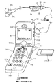
図1は、本例の携帯電話端末100の外観の一例を示した図である。本例の携帯電話端末100は、第1筐体110と第2筐体120とを接合部101で回動自在に接合させたいわゆる折り畳み型の携帯電話端末として構成してある。図1は、両筐体110,120を開いた状態で示してあり、その開いたときに内側になる面の第1筐体110側には、携帯電話として使用される複数のキーで構成されるキー入力部111が配置してある。キー入力部111として用意されたキーとしては、0〜9の数字や*,#の記号のキーや、発信操作などを行うキーや、各種機能を設定するキーが用意されている。その機能キーの内の1つのキー111aは、電話機能を停止させて、オーディオ再生機能だけを作動させるモードを設定及び解除するためのキーとしてある。
【0016】
また、一部のキー111b,111cについては、第2筐体120側に配置してある。さらに、第1筐体110の側面には、回転操作と押下操作とが可能なジョグダイヤル部112が配置してあり、このジョグダイヤル部112の操作によっても各種操作が可能としてある。ジョグダイヤル部112の操作によって、オーディオ再生機能を操作することも可能としてある。
【0017】
また、第1筐体110の下端部には通話用のマイクロホン113が配置してあり、第2筐体120の上端部には通話用のスピーカ122が配置してあり、このマイクロホン113とスピーカ122とを通話者の口と耳元に近づけることで通話ができるようにしてある。第2筐体120の中央部には、表示部123を構成する表示パネルが配置してあり、数字,文字,図形などにより、動作状態や登録された電話番号、受信した文字メールなどの電話に関連した各種表示が可能としてある。また、後述するオーディオ再生機能に関連した表示も可能としてある。
【0018】
第1筐体110には、メモリカード装着部114が設けてあり、例えば筐体の側面側からメモリカード10を挿入させて装着できるようにしてある。本例の場合に使用可能なメモリカード10としては、例えばスティク状(細長の薄板状)に構成された樹脂パッケージ内に不揮発性の半導体メモリを収納させたものを使用する。
【0019】
第2筐体120には、上端にホイップアンテナ121が取付けてあり、側面部に各種端子が配置してある。具体的には、ヘッドホンジャック124と、オーディオ入力ジャック125と、データ通信用ポート126とが配置してある。ヘッドホンジャック124については、ヘッドホン装置に供給するオーディオ信号(音声信号)の出力部と、ヘッドホン装置が内蔵するマイクロホンが拾った音声信号の入力部と、ヘッドホン装置に取付けられたリモートコントロール装置と通信を行うための入出力部とが、一体化されている。データ通信用ポート126については、例えばパーソナルコンピュータ装置などと接続するためのポートであり、例えばUSB(Universal Serial Bus)と称される規格のインターフェース用ポート、或いはIEEE(The Institute of Electrical and Electronics Engineers )1394規格のインターフェース用ポートとする。
【0020】
ヘッドホンジャック124に装着されるプラグ121を備えたヘッドホン装置20としては、その信号線の途中にリモートコントロール部22が取付けてある。このリモートコントロール部22には、表示部23と、キー24とボリュームと、マイクロホン26とが取付けてある。そして、信号線の先端部には、左右のヘッドホンユニット27L,27Rが取付けてある。
【0021】
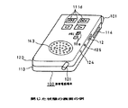
図2は、本例の携帯電話端末100を閉じた状態の表面側(即ち第2筐体120側の面)を示した図である。この面には、オーディオ再生のための操作を行う複数のキー111dと、再生音量を調整するためのボリュームキー111eが配置してある。さらに、再生されたオーディオを出力させるスピーカ143が配置してある。このスピーカ143は、電話の着信時の呼び出し音などを鳴らすためにも使用される。
【0022】
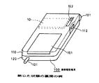
図3は、本例の携帯電話端末100を閉じた状態の裏面側(即ち第1筐体110側の面)を示した図である。この面には、バッテリ(二次電池)の装着部151が設けてあると共に、装着部141に装着されたメモリカード10を取り外すためのリジェクトスイッチ152が配置してある。
【0023】
次に、本例の携帯電話端末100の内部構成を、図4を参照して説明する。無線電話用の回路としては、アンテナ121がアンテナ共用器131を介して受信回路132と送信回路134に接続してある。受信回路132では、指示されたチャンネルの受信処理を行い、受信回路132で受信された信号を、音声処理部133に供給して、無線伝送された音声信号や各種データを復調して抽出し、音声信号についてはスピーカ122から出力させる。また、マイクロホン113が出力する音声信号を音声処理部133に供給して、無線伝送用に変調するなどの処理を行い、その処理された信号を送信回路134で所定のチャンネルの送信信号とする送信処理を行い、その送信信号をアンテナ121から無線送信させる。これらの音声処理部133と受信回路132と送信回路134での処理は、中央制御ユニット(CPU)135の制御により実行される。CPU135は、この携帯電話端末内での各種信号処理を制御するマイクロプロセッサであり、オーディオ再生機能についても、このCPU135が制御する。
【0024】
また、受信回路132には、着信検出回路132aが接続してあり、受信回路132で基地局から受信した制御信号などから、この端末100への着信を着信検出回路132aで検出するようにしてある。着信検出回路132aで着信を検出したときには、着信検出情報をCPU135に供給し、CPU135に必要な処理を実行する。ここでの着信に必要な処理としては、例えば着信音を鳴らす処理がある。着信音を鳴らす処理の詳細については後述する。
【0025】
CPU135には、この端末の動作に必要な情報が記憶されるROM136と、電話帳情報などのユーザが登録した情報が記憶されるRAM137とが接続してあり、CPU135が随時記憶情報を読出すようにしてある。この場合、ROM136は、所定の処理を行ったとき一部の記憶データの書換えが可能なフラッシュメモリとしてあり、電話機能に関する登録情報を書き込ますようにしてある。このROM136に記憶される電話機能に関する登録情報としては、この電話端末に固有の識別番号であるIDデータや、無線電話会社への契約の有無の情報や、契約を行った場合には、電話会社から付与された電話番号の情報などがある。また、オーディオ再生機能に関する契約が必要な場合には、その契約に関する情報をROM136に書き込ませるようにしても良い。
【0026】
また、ROM136の一部のエリアが、着信音のデータの記憶部として設定してあり、この端末への着信があったとき、CPU135の制御で、このエリアに記憶された着信音のデータの中の、予め選択されたデータを読み出して、スピーカ122(又は図示しない着信音用の専用のスピーカ)から着信音を電子音として鳴らすようにしてある。また本例においては、この電子音を着信音として鳴らす処理の他に、後述するオーディオ再生機能を利用して着信音を鳴らす処理が実行できるようにしてある。電子音を着信音として鳴らす場合(第1のモード)と、オーディオ再生機能を利用して着信音を鳴らす場合(第2のモード)とは、キー入力部111又はジョグダイヤル部112の操作によりモード設定を行うことで、いずれかのモードがCPU135に登録されて選択できるようにしてある。
【0027】
キー入力部111やジョグダイヤル部112を操作した情報は、CPU135に供給され、CPU135がその操作情報に基づいた動作を実行させるようにしてある。表示部123での表示についても、CPU135が制御する。ここまで説明した構成は、基本的には電話機能に関連した構成である。
【0028】
次に、オーディオ再生機能に関した構成について説明すると、本例の場合には、オーディオデータを所定の方式(例えばATRACK3方式)で圧縮されたデータを、メモリカード10に記憶させるようにしてある。このオーディオデータが記憶されたメモリカード10がメモリカード装着部114に装着されたとき、メモリカード10の記憶データが、CPU135の制御によりデコーダ138に供給され、デコーダ138で圧縮されたデータの逆圧縮処理を行って元のデータに戻し、戻されたデータをデジタル・アナログ変換器139に供給して、アナログオーディオ信号とし、その変換されたオーディオ信号を出力端子124aに供給する。この出力端子124aは、図1に示すヘッドホンジャック124の内部に配された端子である。
【0029】
出力端子124aに得られる信号には、デジタル・アナログ変換器139の出力と、音声処理部133からの通話用音声の出力とが、加算器140で加算されて供給されるようにしてあり、電話端末として通話を行っている際には、ヘッドホン装置20で通話用音声を聞き取ることもできるようにしてある。そして、出力端子124aに接続されたヘッドホン装置にそのオーディオ信号を供給して出力させる。なお、デジタル・アナログ変換器139の出力に対して、増幅などのアナログ信号処理を行う場合もある。
【0030】
また、デジタル・アナログ変換器139が出力するオーディオ信号を、増幅器142を介して端末の表面に取付けられたスピーカ143に供給して出力させることも可能としてある。デジタル・アナログ変換器139の出力系統の選択は、CPU135により制御される。また、後述するように、オーディオ再生機能を利用して着信音を鳴らす場合にも、メモリカード10から着信音用として予め登録された区間のオーディオデータを読み出して、デジタル・アナログ変換器139から出力されるオーディオ信号を、端末の表面に取付けられたスピーカ143に供給して、このスピーカ143から着信音を鳴らす。
【0031】
本例のオーディオ再生機能部は、入力したオーディオ信号(又は音声信号)を、装着されたメモリカード10に記録(記憶)させる機能も備える。この記録機能のために、デジタルオーディオデータの入力端子125を備えて、その入力端子125に得られるオーディオデータを、デコーダ138に供給する。本例のデコーダ138は、この記録用に入力データをエンコードするエンコーダとしての機能も可能としてあり、CPU135の制御でエンコードされたデータを、メモリカード装着部114に装着されたメモリカード10に記憶させるようにしてある。なお、デコーダ138でのデコード処理やエンコード処理は、ここでは音楽などのオーディオデータを処理するのに適した方式の処理としてある。
【0032】
図1に示すヘッドホンジャック124は、図4に示す出力端子124aの他に、ヘッドホンに内蔵されたマイクロホンからの音声信号の入力端子124bと、リモートコントロール用の入出力端子124cとを備える。入力端子124bに得られる音声信号については、アナログ/デジタル変換器141を介してデコーダ138に供給し、オーディオデータの場合と同様にエンコードして、メモリカード10に記憶させることもできるようにしてある。また、入力端子124bに得られるマイクロホンからの音声信号については、音声処理部133に供給して、マイクロホン113から入力した音声と同様に、通話用音声として処理できるようにしてある。リモートコントロール用の入出力端子124cは、CPU135が、ヘッドホン装置20内のリモートコントロール部22と通信を行うための端子であり、リモートコントロール部22内の表示部23での表示をCPU135が制御すると共に、キー24の操作情報などをCPU135が判断する。なお、リモートコントロール用の信号をオーディオ信号(音声信号)に重畳して、リモートコントロール用の入出力端子124cを出力端子124aと共通の端子とすることも可能である。
【0033】
また、本例の携帯電話端末100は、パーソナルコンピュータ装置などの情報機器と通信を行うためのデータ通信用ポート126を備えて、そのポート126にインターフェース部144が接続してあり、インターフェース部144を介してポート126と接続された相手側の機器と、CPU135及びデコーダ138が通信をできるようにしてある。このポート126を使用した外部の機器との通信では、例えば外部の機器からポート126に供給されるオーディオデータを、デコーダ138に供給して、記録(記憶)用に圧縮して、メモリカード装着部114に装着されたメモリカード10にそのデータを記憶させたり、或いはメモリカード10に記憶されたオーディオデータを、デコーダ138で逆圧縮し、そのデータをポート126に接続された機器に供給すること等が可能である。また、無線電話回線を経由してこの端末が受信したデータを、CPU135の制御でポート126に供給して、外部の機器に供給したり、逆に外部の機器からポート126に得られるデータを、CPU135の制御で無線電話回線側に送出させることもできる。
【0034】
また、無線電話回線を経由してこの端末の受信回路132が受信したオーディオデータなどの各種データを、CPU135の制御で、メモリカード114に記憶させることも可能としてある。この場合、受信したデータが既に記憶用にエンコードされたデータである場合、デコーダ138でのエンコード処理を省略してメモリに書き込ませても良い。
【0035】
このようにして、本例の携帯電話端末には、オーディオデータや音声データを記録(記憶)し再生する機能部が内蔵されている。なお、本例の場合には、メモリカード10が装着部114から着脱自在であるので、例えば他のオーディオ機器でオーディオデータを記憶させたメモリカード10を、本例の携帯電話端末100に装着して、再生させることも可能である。
【0036】
次に、本例の携帯電話端末にて、着信時に着信音を鳴らす処理を、図5,図6のフローチャートを参照して説明する。本例の場合には、既に説明したように、電子音を着信音として鳴らすいわゆる通常の着信音処理(第1のモード)と、オーディオ再生機能を利用して着信音を鳴らす処理(第2のモード)とが実行できるようにしてある。ここで、第2のモードでオーディオ再生機能を利用して着信音を鳴らす場合には、着信音として鳴らす区間を登録する設定処理を予め行う必要がある。
【0037】
図5は、この登録処理の一例を示したものである。まず、メモリカード10に記憶されたオーディオ(音楽又は音声)を再生させて、その再生音をスピーカ又はヘッドホンから出力させ、着信音登録モードを何らかのキー操作で設定させる。着信音登録モードを設定させてから、音楽の再生を行うようにしても良い。
【0038】
そしてCPU135は、その音楽の再生中であるか否か判断し(ステップS11)、再生中でないときには登録処理を中断させる。再生中であると判断したときには、ジョグダイヤル部112を押下させるクリック操作があったか否か判断する(ステップS12)。クリック操作がない場合には、再生が続く限り、クリック操作の有無を判断する。
【0039】
ステップS12でクリック操作があると判断したとき、そのクリック操作が1回目の操作であるか否か判断し(ステップS13)、1回目の操作であるとき、そのときのメモリカード10から読み出して再生しているオーディオデータのメモリ上の記憶アドレスを、CPU135内に始点アドレスとして一時記憶させる(ステップS14)。この一時記憶をした後は、ステップS11の判断に戻る。
【0040】
そして、ステップS12でクリック操作があると判断し、ステップS13でそのクリック操作が1回目でないと判断したとき、そのクリック操作が2回目であるか否か判断する(ステップS15)。ここで2回目であると判断したとき、そのときのメモリカード10から読み出して再生しているオーディオデータのメモリ上の記憶アドレスを、CPU135内に終点アドレスとして一時記憶させる(ステップS16)。そして、CPU135内に一時記憶された始点アドレスと終点アドレスを、着信メロディ用インデックスとして、CPU135に接続されたメモリに記憶させる(ステップS17)。なお、この記憶時には、このとき再生した曲(音楽など)やメモリカード10を識別するのに必要がデータについても記憶させておく。
【0041】
また、ステップS15で2回目のクリックでないと判断したときには、CPU135の内部でのクリック回数の設定をクリアしておく(ステップS18)。
【0042】
このように処理されることで、オーディオ再生機能部を利用してメモリカード10から読み出した音楽を再生させて、その再生音楽中の任意の区間を着信音として登録できるようになる。即ち、最初にジョグダイヤル部112を押下させるクリック操作したときに再生中の箇所が、着信音の先頭位置として登録され、次にクリック操作したときに再生中の箇所が、着信音の末尾位置として登録される。従って、ユーザ操作で音楽中に任意の区間を着信音として登録できるようになる。なお、登録される音楽(音声)の長さ(時間)については、予め制限を設けるようにしても良い。
【0043】
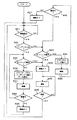
次に、このように登録された着信音を着信時に出力させる処理を、図6のフローチャートを参照して説明する。着信音を着信時に出力させる処理は、CPU135の制御で実行されるもので、CPU135は、着信検出回路132aで着信を検出したか否か判断し(ステップS21)、着信を検出するまで待機する。ステップS21で着信を検出したとき、CPU135は着信メロディ用インデックスの登録があるか否か判断する(ステップS22)。
【0044】
ここで、着信メロディ用インデックスの登録がないと判断した場合には、通常の着信音を鳴らす処理に移る。即ち、オフフック操作があるか否か判断し(ステップS23)、オフフック操作が検出されないとき、着信音用のメモリの記憶エリアから、電子音の着信音のデータを読み出し(ステップS24)、そのデータによる電子音の着信音を鳴動させる(ステップS25)。そして、着信が継続しているか判断し(ステップS26)、着信状態でなくなったと判断したとき、着信音の鳴動を停止させて(ステップS27)、ステップS21の判断に戻って着信待機状態となる。
【0045】
そして、ステップS26で着信が継続していると判断したとき、ステップS23のオフフック操作の判断に戻る。ステップS23でオフフック操作があると判断されたときには、着信音の鳴動を停止させて(ステップS28)、通話状態に移り(ステップS29)、通話が終了するいわゆる終話となったか否か判断し(ステップS30)、終話を検出したときステップS21の判断に戻って着信待機状態となる。
【0046】
そして、ステップS22で着信メロディ用インデックスの登録があると判断したとき、オーディオ再生機能を利用して着信音を鳴らす処理に移る。このときには、オフフック操作があるか否か判断し(ステップS31)、オフフック操作が検出されないとき、着信メロディ用インデックスが登録された区間のオーディオデータをメモリカード10から読み出し(ステップS32)、そのオーディオデータを再生処理して、スピーカ143から出力させて、着信音として鳴動させる(ステップS33)。この着信音として鳴動させる場合には、着信メロディ用インデックスが登録された区間のオーディオデータを繰り返し再生させる。その際には、1回の再生が終了した後に、次の再生を行うまでの間、1秒程度の時間をあけるようにしても良い。そして、着信が継続しているか判断し(ステップS34)、着信状態でなくなったと判断したとき、着信音の鳴動を停止させて(ステップS35)、ステップS21の判断に戻って着信待機状態となる。
【0047】
そして、ステップS34で着信が継続していると判断したとき、ステップS31のオフフック操作の判断に戻る。ステップS31でオフフック操作があると判断されたときには、着信音の鳴動を停止させて(ステップS28)、通話状態に移り(ステップS29)、通話が終了するいわゆる終話となったか否か判断し(ステップS30)、終話を検出したときステップS21の判断に戻って着信待機状態となる。
【0048】
このようにして、オーディオ再生機能を利用してメモリカード10に記憶されたオーディオデータを利用して、着信音を鳴らすようにしたことで、ユーザが所望の曲を、オーディオ再生を行う場合と同様の高音質で鳴らすことができるようになる。
【0049】
なお、ここまで説明した処理では、オーディオ再生機能を利用した着信音を鳴らす処理として、メモリカード10から該当する区間のオーディオデータを、着信時に読み出して、その読み出したデータから着信音を生成させるようにしたが、図5のフローチャートのステップS17で着信メロディ用インデックスの登録があった時点で、該当する区間のオーディオデータをメモリカード10から読み出して、CPU135に接続されたメモリに記憶させるようにしても良い。
【0050】
即ち、例えば図7のフローチャートに示すように、インデックスが設定された区間のオーディオデータをCPU135に接続されたRAM137に転送させ(ステップS41)、その転送作業が終了したか否か判断し(ステップS42)、終了したとき、着信メロディの設定を完了させる(ステップS43)。そして、オーディオ再生機能を利用して着信音を鳴らすモードが設定されている場合には、RAM137に転送されたオーディオデータを読み出して、その読み出したオーディオデータの再生処理を行って、着信音を鳴らすようにすれば良い。このようにすることで、例えばメモリカード10に後から別の曲を記憶させた場合や、メモリカードそのものが端末から外された場合であっても、登録時の曲を着信音として鳴らせるようになる。
【0051】
なお、図7のフローチャートに示すように、オーディオデータをメモリカード10から読み出して別のメモリに転送させて記憶させる場合には、オーディオデータに何らかの方式変換処理を施すようにしても良い。即ち、例えばメモリカード10には、ATRACK3方式で記憶されたオーディオデータを、別の圧縮方式で符号化されたオーディオデータとして、RAMなどに記憶させるようにしても良い。
【0052】
また、図5,図6のフローチャートの処理では、着信メロディ用のインデックスの登録があるとき、自動的にオーディオ再生機能を利用して着信音を鳴らすモード(第2のモード)が設定されて、着信メロディ用のインデックスの登録がないとき、通常の電子音により着信音を鳴らす処理(第1のモード)が設定されるようにしたが、着信メロディ用のインデックスの登録の有無とは別に、この第1,第2のモードがユーザ操作で設定できるようにしても良い。即ち、着信メロディ用のインデックスを登録した場合でも、第1のモードを設定して、通常の電子音による着信音を鳴らせるようにしても良い。この場合、第2のモードを設定した状態で、着信メロディ用のインデックスの登録がない場合や、インデックスの登録があっても、その曲のデータがメモリカード10から消去された場合や、メモリカード10が端末100から外された場合には、自動的に第1のモードに変化するようにすれば良い。
【0053】
なお、ここまでの説明では、装着されたメモリカードには、オーディオデータを記録(記憶)させて、その記録されたオーディオデータを再生するようにしたが、携帯電話端末が内蔵したマイクロホンが収録した音声データや、電話として使用中の通話音声のデータを、メモリカード内のメモリに記憶させて、必要なときに再生する音声記録再生装置としても良い。この場合、記憶させるデータの処理としては、音楽などのオーディオデータを記憶させる場合のエンコード処理(圧縮処理)とデコード処理(逆圧縮処理)と同じでも良いが、会話用音声に適したより圧縮率の高いエンコード処理やデコード処理を行うようにしても良い。
【0054】
また、上述した実施の形態では、使用される記録媒体(記憶媒体)としてメモリカードを使用したが、他の記録媒体を使用しても良い。また、メモリを記憶媒体として使用する場合に、そのメモリが端末装置内に予め組み込まれたものを使用して、交換できないようにしても良い。
【0055】
また、上述した実施の形態では、通信端末として無線電話回線を使用する携帯電話端末としたが、基地局からの呼び出し信号を受信したとき、同様の着信音(呼び出し音)を鳴らす処理を行う他の無線通信システム用の無線通信端末にも適用できるものである。
【0056】
【発明の効果】
本発明によると、音楽又は音声の再生機能を利用して着信音を鳴らすことが可能になる。従って、例えば音楽再生用に用意されたデータの一部を利用して、音質の良い音楽を着信音として鳴らすことが可能になる。また、音楽再生機能部が備えるメモリに好みの曲を入力させておくことで、簡単に所望の曲の一部を着信音として使用できるようになる。
【0057】
この場合、再生機能部に記憶された音楽又は音声のデータは、外部から通信端末装置に取り込んだデータであることで、例えば外部から好みの曲を入力させることで、ユーザが所望の曲を簡単に着信音として設定できるようになる。
【0058】
また、外部からの音楽又は音声のデータの取り込みは、通信端末が備える無線通信手段が受信したデータとしたことで、無線電話回線などの通信手段を使用して、簡単に所望の音楽などを着信音として設定できるようになる。
【0059】
また、着信音として鳴らす区間の設定は、音楽又は音声を再生中に、所定の操作を行うことで設定するようにしたことで、ユーザが音楽などを聞きながら簡単に設定できるようになる。
【0060】
また、再生機能部からの音楽などを着信音として鳴らすようにモードが設定された状態で、着信音として鳴らすデータが再生機能部に記憶されてないとき、又は鳴らす区間の設定がないとき、予め用意された着信音用データの中の所定のデータによる着信音を鳴らすようにしたことで、着信音が適切なものに自動的に選択されるようになる。
【0061】
また、再生機能部が備えるデータ記憶部は、着脱自在なメモリであることで、例えば他の記録装置にて音楽などが記憶されたメモリを、この端末装置に装着させることで、簡単にユーザが所望の音楽を着信音として設定できるようになる。
【0062】
また、このメモリが着脱自在なメモリである場合に、そのメモリの装着がないとき、予め用意された着信音用データの中の所定のデータによる着信音を鳴らすようにしたことで、着信音が適切なものに自動的に選択されるようになる。
【0063】
また、再生機能部に記憶されたデータの一部の区間を着信音として設定したとき、その設定された区間の記憶データを、着信音記憶用のメモリに記憶させて、着信時のそのメモリから読み出したデータで着信音を鳴らすようにしたことで、着信時には簡単な制御で着信音を鳴らせるようになる。
【0064】
また、このように着信音記憶用のメモリに記憶させる際に、再生機能部に記憶されたデータに所定の変換処理を施してメモリに記憶させることで、再生機能部に記憶された音楽又は音声のデータの記憶形式と、着信音記憶用のメモリのデータの記憶形式が異なる場合でも対処できるようになる。
【図面の簡単な説明】
【図1】本発明の一実施の形態による端末装置の例(開いた状態)を示す斜視図である。
【図2】図1に示した例の端末装置を閉じた状態の表面の例を示す斜視図である。
【図3】図1に示した例の端末装置を閉じた状態の裏面の例を示す斜視図である。
【図4】本発明の一実施の形態による端末装置の内部構成の例を示すブロック図である。
【図5】本発明の一実施の形態による着信音の登録処理例を示すフローチャートである。
【図6】本発明の一実施の形態による着信音を鳴らす処理例を示すフローチャートである。
【図7】本発明の他の実施の形態による着信音のデータの転送処理例を示すフローチャートである。
【符号の説明】
10…メモリカード、20…ヘッドホン装置、22…リモートコントロール部、23…表示部、24…キー、25…ボリューム、26…マイクロホン、100…携帯電話端末、110…第1筐体、111…キー入力部、113…マイクロホン、114…メモリカード装着部、120…第2筐体、121…アンテナ、122…スピーカ、123…表示部、124…ヘッドホンジャック、125…オーディオ入力ジャック、126…データ通信用ポート、132…受信回路、132a…着信検出回路、133…音声処理部、134…送信回路、135…中央制御ユニット(CPU)、138…デコーダ(エンコーダ)、139…デジタル・アナログ変換器、141…アナログ/デジタル変換器、161…電源回路、162,163,165…電源供給スイッチ、164…モード切換スイッチ[0001]
BACKGROUND OF THE INVENTION
The present invention relates to a ringtone output method for a communication terminal and a communication terminal apparatus suitable for application to, for example, a radiotelephone apparatus called a mobile phone terminal.
[0002]
[Prior art]
2. Description of the Related Art Conventionally, various types of communication terminals that are used as wireless telephone devices have been combined with other functions to form composite terminals. That is, in general, a radio telephone device is configured to be small and portable, and is always carried by a user. Therefore, in addition to the function as a radio phone, the terminal device has a clock function and a schedule management function. Some of them are displayed on a display device.
[0003]
Here, as a composite terminal with higher functionality, it has been proposed to incorporate an audio playback device in a mobile terminal device. That is, with the recent increase in capacity of semiconductor memory and the improvement of audio data compression technology, audio data of, for example, several tens of minutes to several hours can be stored in a memory built in a memory card. . A device in which headphones are attached to a small playback device using this memory card as a recording medium (storage medium) and audio is listened to using the headphones has already been put into practical use.
[0004]
By incorporating an audio playback device using such a memory as a recording medium in a mobile phone terminal, when the mobile phone terminal is not used for calling, headphones can be attached to the terminal to listen to audio. The use of mobile phone terminals will expand.
[0005]
In addition, by attaching an audio playback device to a mobile phone terminal, for example, audio data can be downloaded from the center to the terminal via a wireless telephone line, and the audio data can be stored in a memory card attached to the terminal. Data can be easily distributed to users, which is very convenient.
[0006]
By the way, the above-described cellular phone terminal is configured to sound a ringing tone when receiving an incoming call. As this ringing tone, there is a case where a short melody of several seconds to 10 seconds is sounded as an electronic sound, in addition to an electronic sound that simply sounds “beep”. In order to play such a melody, when a desired melody is selected from melody stored in advance in an internal memory when the terminal is manufactured, and when a user inputs a desired melody by key operation, There is a case where a server in which a melody for receiving an incoming call is accessed via a telephone line, and data of a desired melody is downloaded from the server and stored in a terminal.
[0007]
By playing such a melody electronic sound as a ringing tone, the terminal used by each person can be distinguished, and for example, it becomes easy to know who has received an incoming call. In this specification, a ringing tone that the terminal rings when receiving an incoming call is referred to as a ringing tone.
[0008]
[Problems to be solved by the invention]
However, when a melody prepared in advance in the memory inside the terminal is played, there is a problem that the type of melody is limited to that prepared in advance. Similarly, when downloading desired melody data from the server, there is a problem that only the melody prepared on the server side can be set. In addition, when inputting a melody by key operation, there is a problem that a complicated key operation in accordance with the pitch of the melody is required.
[0009]
Also, the conventional ringtone of a melody is such that a melody is output by generating an electronic sound having a predetermined pitch based on the data of the melody inside the terminal, and generating a double sound such as a double sound. Some of them are designed to be able to do this, but basically they are electronically synthesized sounds, and there is a problem of poor change in timbre.
[0010]
An object of the present invention is to make it possible to easily generate a ringtone having a good sound quality by using arbitrary music in this type of communication terminal device.
[0011]
[Means for Solving the Problems]
According to the present invention, when a first mode is set in a communication terminal that performs wireless communication with a predetermined station and incorporates a music or voice playback function, data for a ring tone that is prepared in advance when an incoming call is set. When the second mode is set by outputting a ring tone with the data selected from among the items, an incoming call with data in a preset section of the music or voice data stored in the playback function unit at the time of the incoming call The sound is output.
[0012]
By doing in this way, it becomes possible to ring a ringtone using the reproduction function of music or voice.
[0013]
DETAILED DESCRIPTION OF THE INVENTION
Hereinafter, an embodiment of the present invention will be described with reference to the accompanying drawings.
[0014]
In this example, for example, various types of digital data are wirelessly transmitted to and from a base station, so that the present invention is applied to a wireless telephone device (mobile phone terminal) that performs a telephone call or data communication. The mobile phone terminal of this example incorporates an audio playback function unit in addition to the function unit as a wireless telephone.
[0015]
FIG. 1 is a diagram showing an example of the appearance of the
[0016]
Some of the
[0017]
In addition, a
[0018]
The
[0019]
The
[0020]
As the
[0021]
FIG. 2 is a diagram showing a front surface side (that is, a surface on the
[0022]
FIG. 3 is a view showing the back surface side (that is, the surface on the
[0023]
Next, the internal configuration of the
[0024]
An incoming
[0025]
The
[0026]
In addition, a part of the
[0027]
Information obtained by operating the
[0028]
Next, the configuration related to the audio playback function will be described. In the case of this example, data obtained by compressing audio data by a predetermined method (for example, ATRACK3 method) is stored in the
[0029]
In the signal obtained at the
[0030]
Also, the audio signal output from the digital /
[0031]
The audio playback function unit of this example also has a function of recording (storing) the input audio signal (or audio signal) in the attached
[0032]
In addition to the
[0033]
In addition, the
[0034]
Various data such as audio data received by the receiving circuit 132 of this terminal via a wireless telephone line can be stored in the
[0035]
In this way, the cellular phone terminal of this example has a built-in function unit that records (stores) and reproduces audio data and audio data. In this example, since the
[0036]
Next, a process for sounding a ring tone when receiving an incoming call in the mobile phone terminal of this example will be described with reference to the flowcharts of FIGS. In the case of this example, as already described, so-called normal ring tone processing (first mode) for playing an electronic sound as a ring tone and processing for ringing a ring tone using an audio playback function (second mode) Mode). Here, when a ring tone is sounded using the audio playback function in the second mode, it is necessary to perform in advance a setting process for registering a section sounded as a ring tone.
[0037]
FIG. 5 shows an example of this registration process. First, the audio (music or voice) stored in the
[0038]
Then, the
[0039]
When it is determined in step S12 that there is a click operation, it is determined whether or not the click operation is the first operation (step S13), and when it is the first operation, it is read from the
[0040]
Then, when it is determined that there is a click operation in step S12 and it is determined in step S13 that the click operation is not the first time, it is determined whether or not the click operation is the second time (step S15). Here, when it is determined that it is the second time, the storage address on the memory of the audio data read out and reproduced from the
[0041]
If it is determined in step S15 that it is not the second click, the setting of the number of clicks in the
[0042]
By processing in this way, the music read from the
[0043]
Next, a process for outputting the ringtone registered in this way upon arrival will be described with reference to the flowchart of FIG. The process of outputting a ringtone when receiving an incoming call is executed under the control of the
[0044]
Here, if it is determined that the ringtone melody index has not been registered, the process proceeds to a process for sounding a normal ringtone. That is, it is determined whether or not there is an off-hook operation (step S23), and when no off-hook operation is detected, electronic ringtone data is read from the memory area of the ringtone memory (step S24), and the data is An electronic ringtone is sounded (step S25). Then, it is determined whether the incoming call continues (step S26). When it is determined that the incoming call is no longer being received, the ringing tone is stopped (step S27), and the process returns to the determination of step S21 to enter the incoming call waiting state.
[0045]
When it is determined in step S26 that the incoming call continues, the process returns to the determination of the off-hook operation in step S23. When it is determined in step S23 that there is an off-hook operation, ringing of the ringtone is stopped (step S28), the call state is entered (step S29), and it is determined whether or not a so-called end of call is ended (step S29). In step S30), when the end of the call is detected, the process returns to the determination in step S21 to enter the incoming call waiting state.
[0046]
When it is determined in step S22 that the incoming melody index has been registered, the process proceeds to a process for sounding a ringtone using the audio reproduction function. At this time, it is determined whether or not there is an off-hook operation (step S31). If no off-hook operation is detected, the audio data of the section in which the incoming melody index is registered is read from the memory card 10 (step S32). Is reproduced and output from the
[0047]
When it is determined in step S34 that the incoming call continues, the process returns to the determination of the off-hook operation in step S31. When it is determined in step S31 that there is an off-hook operation, ringing of the ringtone is stopped (step S28), the call state is entered (step S29), and it is determined whether or not a so-called end of call is reached (step S29). In step S30), when the end of call is detected, the process returns to the determination in step S21 to enter the incoming call waiting state.
[0048]
In this way, by using the audio data stored in the
[0049]
In the process described so far, as a process for sounding a ring tone using the audio playback function, the audio data of the corresponding section is read from the
[0050]
That is, for example, as shown in the flowchart of FIG. 7, the audio data in the section in which the index is set is transferred to the RAM 137 connected to the CPU 135 (step S41), and it is determined whether or not the transfer operation is completed (step S42). When finished, the setting of the incoming melody is completed (step S43). If a mode for sounding a ringtone using the audio playback function is set, the audio data transferred to the RAM 137 is read out, and the read-out processing of the read audio data is performed to sound the ringtone. You can do that. In this way, for example, even when another song is later stored in the
[0051]
As shown in the flowchart of FIG. 7, when audio data is read from the
[0052]
Also, in the processing of the flowcharts of FIGS. 5 and 6, when an index for a ringing melody is registered, a mode (second mode) for automatically ringing a ringtone using the audio playback function is set, When the index for ringtones is not registered, the process to ring the ringtone using the normal electronic sound (first mode) is set. The first and second modes may be set by a user operation. That is, even when an index for a ringing melody is registered, the first mode may be set so that a ringing tone using a normal electronic sound is generated. In this case, when the second mode is set, there is no registration of the index for the incoming melody, or even if the index is registered, the data of the song is deleted from the
[0053]
In the above description, audio data is recorded (stored) in the installed memory card, and the recorded audio data is played back. However, the microphone built in the mobile phone terminal records it. The voice recording / playback apparatus may be configured to store voice data or data of a call voice being used as a telephone in a memory in a memory card and reproduce the data when necessary. In this case, the processing of the data to be stored may be the same as the encoding processing (compression processing) and decoding processing (decompression processing) in the case of storing audio data such as music, but the compression rate is more suitable for speech for conversation. High encoding processing and decoding processing may be performed.
[0054]
In the above-described embodiment, the memory card is used as the recording medium (storage medium) to be used. However, other recording media may be used. In addition, when a memory is used as a storage medium, the memory may be preinstalled in the terminal device so that it cannot be replaced.
[0055]
In the above-described embodiment, a mobile phone terminal using a radio telephone line is used as a communication terminal. However, when a call signal from a base station is received, a similar ringing tone (ring tone) is performed. The present invention can also be applied to a wireless communication terminal for the wireless communication system.
[0056]
【The invention's effect】
According to the present invention, it is possible to ring a ringtone using a music or voice reproduction function. Therefore, for example, it is possible to play music with good sound quality as a ringtone by using a part of data prepared for music playback. In addition, by inputting a favorite song into a memory provided in the music playback function unit, a part of the desired song can be easily used as a ring tone.
[0057]
In this case, the music or audio data stored in the playback function unit is data taken into the communication terminal device from the outside. For example, by inputting a favorite song from the outside, the user can easily select a desired song. Can be set as ringtone.
[0058]
In addition, external music or voice data can be taken in as data received by the wireless communication means provided in the communication terminal, so that the desired music can be easily received using communication means such as a wireless telephone line. It can be set as sound.
[0059]
In addition, the section to be ringed as a ringtone can be set by performing a predetermined operation during playback of music or voice, so that the user can easily set it while listening to music.
[0060]
In addition, when the mode is set to ring the music from the playback function unit as a ring tone, when the data to be ringed as a ring tone is not stored in the playback function unit or when the section to be played is not set, By ringing a ringtone according to predetermined data in the prepared ringtone data, an appropriate ringtone is automatically selected.
[0061]
In addition, the data storage unit included in the playback function unit is a detachable memory. For example, the user can easily attach a memory in which music or the like is stored in another recording device to the terminal device. Desired music can be set as a ringtone.
[0062]
In addition, when this memory is a detachable memory, when the memory is not installed, a ringing tone by a predetermined data in the ringtone data prepared in advance is sounded. The correct one will be automatically selected.
[0063]
When a part of the data stored in the playback function section is set as a ringtone, the stored data of the set section is stored in the memory for storing the ringtone, and the memory at the time of the incoming call is stored. By ringing a ring tone with the read data, it is possible to ring a ring tone with simple control when an incoming call is received.
[0064]
In addition, when storing in the memory for storing ringtones in this way, the music or audio stored in the playback function unit is stored by performing a predetermined conversion process on the data stored in the playback function unit and storing the data in the memory. It is possible to cope with a case in which the data storage format of the data and the data storage format of the ringtone storage memory are different.
[Brief description of the drawings]
FIG. 1 is a perspective view showing an example (opened state) of a terminal device according to an embodiment of the present invention;
FIG. 2 is a perspective view showing an example of a surface in a state where the terminal device of the example shown in FIG. 1 is closed.
FIG. 3 is a perspective view showing an example of a back surface in a state where the terminal device of the example shown in FIG. 1 is closed.
FIG. 4 is a block diagram showing an example of an internal configuration of a terminal device according to an embodiment of the present invention.
FIG. 5 is a flowchart showing an example of a ring tone registration process according to an embodiment of the present invention.
FIG. 6 is a flowchart showing an example of processing for ringing a ring tone according to an embodiment of the present invention.
FIG. 7 is a flowchart showing an example of a ring tone data transfer process according to another embodiment of the present invention.
[Explanation of symbols]
DESCRIPTION OF
Claims (14)
予め用意された着信音用データを出力する第1のモードを設定したとき、上記局からの着信時に、予め用意された着信音用データの中の所定のデータを出力させ、
区間が設定されたデータを出力する第2のモードを設定したとき、上記局からの着信時に、記憶手段に記憶された音楽又は音声のデータの内の予め設定された区間のデータによる着信音を出力させる処理を行い、
上記第2のモードの設定中に、上記記憶手段に該当する音楽又は音声のデータの記憶がないとき、又は、上記記憶手段が取り外されているとき、又は、記憶されたデータに着信音として鳴らす区間の設定がない状態で、所定の局からの着信があったとき、上記第1のモードで着信音を鳴らすようにした
通信端末の着信音出力方法。In the ring tone output method of a communication terminal that performs wireless communication with a predetermined station and has a built-in music or voice playback function,
When the first mode for outputting the ringtone data prepared in advance is set, the predetermined data in the ringtone data prepared in advance is output when a call is received from the station .
When the second mode for outputting the data for which the section is set is set, the ring tone based on the data of the preset section of the music or voice data stored in the storage means is received at the time of arrival from the station. Process to output ,
During the setting of the second mode, when there is no storage of music or voice data corresponding to the storage means, or when the storage means is removed, or the stored data is sounded as a ring tone. A method for outputting a ringtone of a communication terminal in which a ringtone is sounded in the first mode when an incoming call is received from a predetermined station without setting a section .
上記音楽又は音声のデータは、外部から端末内の再生機能部に取り込んだデータである
通信端末の着信音出力方法。The ringtone output method for a communication terminal according to claim 1,
The method for outputting a ringtone of a communication terminal, wherein the music or voice data is data fetched from the outside into a playback function unit in the terminal.
外部から再生機能部への音楽又は音声のデータの取り込みは、上記所定の局を経由した無線通信で行うようにした
通信端末の着信音出力方法。The ringtone output method for a communication terminal according to claim 2,
A method for outputting a ringtone of a communication terminal in which music or audio data is externally imported into a playback function unit by wireless communication via the predetermined station.
上記着信音として鳴らす区間の設定は、上記再生機能部で音楽又は音声を再生中に、所定の操作を行うことで設定する
通信端末の着信音出力方法。The ringtone output method for a communication terminal according to claim 1,
The method of setting a ringing tone as the ringing tone is set by performing a predetermined operation while music or voice is being played back by the playback function unit.
音楽又は音声のデータの記憶し、その記憶したデータの再生を行うデータ再生手段と、
上記無線通信手段で受信した信号から着信を検出する着信検出手段と、
上記着信検出手段が着信を検出したとき、着信音を出力する着信音出力手段と、
上記データ再生手段に記憶されたデータの一部の区間を着信音として設定する設定手段と、
上記着信検出手段が着信を検出したとき、上記設定手段で設定された着信音を出力するよう上記着信音出力手段を制御する制御手段とを備え、
上記制御手段は、上記データ再生手段に記憶されたデータの一部を、着信音のデータとして上記着信音データ記憶手段に記憶させるとき、記憶データに所定の変換処理を施す
通信端末装置。Wireless communication means for performing wireless communication with a predetermined station;
Data reproduction means for storing music or voice data and reproducing the stored data;
An incoming call detection means for detecting an incoming call from a signal received by the wireless communication means;
A ringtone output means for outputting a ringtone when the incoming call detection means detects an incoming call;
Setting means for setting a partial section of the data stored in said data reproduction means as a ringtone,
When the receiving detecting means detects an incoming call, e Bei and control means for controlling the ringtone output unit to output the set ringtone above setting means,
A communication terminal apparatus that performs a predetermined conversion process on stored data when the control means stores a part of data stored in the data reproduction means as ringtone data in the ringtone data storage means .
上記データ再生手段に記憶された音楽又は音声のデータは、外部から通信端末装置に取り込んだデータである
通信端末装置。The communication terminal device according to claim 5 , wherein
The music or voice data stored in the data reproduction means is a communication terminal device which is data taken into the communication terminal device from the outside.
上記データ再生手段への音楽又は音声のデータの取り込みは、上記無線通信手段が受信したデータを取り込ませる
通信端末装置。The communication terminal device according to claim 6 .
The communication terminal device that takes in the data received by the wireless communication means when the music or voice data is taken into the data reproduction means.
上記データ再生手段が備えるデータ記憶部は、着脱自在なメモリである
通信端末装置。The communication terminal device according to claim 5 , wherein
The data storage unit included in the data reproduction means is a detachable memory.
予め用意された着信音が記憶された着信音データ記憶手段をさらに備え、
上記制御手段は、上記メモリが装着されていないことを判断した場合、上記着信音データ記憶手段に記憶されたデータによる着信音を出力させるよう上記着信音出力手段を制御する
通信端末装置。The communication terminal device according to claim 8 , wherein
A ring tone data storage means for storing a ring tone prepared in advance;
A communication terminal apparatus that controls the ring tone output means to output a ring tone based on data stored in the ring tone data storage means when it is determined that the memory is not installed.
予め用意された着信音が記憶された着信音データ記憶手段をさらに備え、
上記制御手段は、上記設定手段が設定した着信音を上記着信音データ記憶手段に記憶させ、上記着信検出手段が着信を検出したとき、上記着信音データ記憶手段に記憶させた着信音を出力させるよう上記着信音出力手段を制御する
通信端末装置。The communication terminal device according to claim 5 , wherein
A ring tone data storage means for storing a ring tone prepared in advance;
The control means stores the ringtone set by the setting means in the ringtone data storage means, and outputs the ringtone stored in the ringtone data storage means when the incoming call detection means detects an incoming call. A communication terminal device for controlling the ring tone output means.
ユーザ操作に応じた操作情報を出力する操作手段をさらに備え、
上記設定手段は、上記再生手段によって上記データが再生されているときに、上記操作手段から出力された第1の操作情報と、次いで出力された第2の操作情報とを受信し、当該第1の操作情報を受信した時点における再生されているデータの位置を始点とし、次いで第2の操作情報を受信した時点における再生されているデータの位置を終点とするデータの区間を着信音として設定する
通信端末装置。The communication terminal device according to claim 5 , wherein
It further comprises an operation means for outputting operation information corresponding to a user operation,
The setting means receives the first operation information outputted from the operation means and the second operation information outputted next when the data is reproduced by the reproduction means, and the first operation information is outputted. The section of the data starting from the position of the reproduced data at the time when the operation information is received and then the end of the position of the reproduced data at the time of receiving the second operation information is set as the ring tone. Communication terminal device.
上記着信音として鳴らす区間の設定は、ユーザ操作によって指定された第1の位置と第2の位置との間を上記着信音として鳴らす区間として設定する
通信端末の着信音出力方法。The ringtone output method for a communication terminal according to claim 4,
The method for setting a section to be ringed as the ringtone is set as a section for ringing as the ringtone between a first position and a second position specified by a user operation.
音楽又は音声のデータの記憶し、その記憶したデータの再生を行うデータ再生手段と、
上記無線通信手段で受信した信号から着信を検出する着信検出手段と、
上記着信検出手段が着信を検出したとき、着信音を出力する着信音出力手段と、
上記データ再生手段に記憶されたデータの一部の区間を着信音として設定する設定手段と、
上記着信検出手段が着信を検出したとき、上記設定手段で設定された着信音を出力するよう上記着信音出力手段を制御する制御手段とを備え、
上記制御手段は、予め用意された着信音用データを出力する第1のモードが設定された状態で、上記着信検出手段が着信を検出した際に、予め用意された着信音用データの中の所定のデータを上記着信音出力手段に供給して出力させ、
上記設定手段により設定された着信音のデータを出力する第2のモードが設定された状態で、上記着信検出手段が着信を検出した際に、上記設定手段により設定されたデータを上記着信音出力手段に供給して出力させると共に、上記第2のモードの設定中に、上記再生機能手段に該当する音楽又は音声のデータの記憶がないとき、又は、上記記憶手段が取り外されているとき、又は、記憶されたデータに着信音として鳴らす区間の設定がない状態で、所定の局からの着信があったとき、上記第1のモードで着信音を鳴らすようにした
通信端末装置。Wireless communication means for performing wireless communication with a predetermined station;
Data reproduction means for storing music or voice data and reproducing the stored data;
An incoming call detection means for detecting an incoming call from a signal received by the wireless communication means;
A ringtone output means for outputting a ringtone when the incoming call detection means detects an incoming call;
Setting means for setting a part of the data stored in the data reproducing means as a ring tone;
Control means for controlling the ring tone output means to output the ring tone set by the setting means when the incoming call detection means detects an incoming call;
The control means, when the first mode for outputting the ringtone data prepared in advance is set, when the incoming call detection means detects an incoming call, Supply predetermined data to the ringtone output means and output it,
When the second mode for outputting the ring tone data set by the setting means is set, when the incoming call detecting means detects an incoming call, the data set by the setting means is output as the ring tone. When the second mode is set and there is no storage of music or voice data corresponding to the playback function means, or when the storage means is removed, or A communication terminal device that sounds a ring tone in the first mode when there is an incoming call from a predetermined station without setting a section to ring as a ring tone in stored data.
上記記憶手段に記憶された音楽又は音声のデータの内の予め設定された区間のデータを、着信用のデータとして所定の変換処理を施して上記記憶手段に記憶させ、
上記局からの着信時に、上記所定の変換処理が施された着信用のデータを上記記憶手段から出力させて着信音を出力させる
通信端末の着信音出力方法。In a method for outputting a ringtone of a communication terminal that performs wireless communication with a predetermined station, stores music or voice data in a storage unit, and stores a music or voice reproduction function stored in the storage unit,
Data of a preset section of music or voice data stored in the storage means is subjected to a predetermined conversion process as incoming data and stored in the storage means,
An incoming call tone output method for a communication terminal, wherein when a call is received from the station, the incoming data subjected to the predetermined conversion process is output from the storage means to output a ringtone.
Priority Applications (4)
| Application Number | Priority Date | Filing Date | Title |
|---|---|---|---|
| JP2000152016A JP4206608B2 (en) | 2000-05-23 | 2000-05-23 | Ringing tone output method for communication terminal and communication terminal apparatus |
| KR1020010027802A KR100767462B1 (en) | 2000-05-23 | 2001-05-21 | Method of generating ring tones using melody and communication terminal apparatus |
| US09/861,789 US7050573B2 (en) | 2000-05-23 | 2001-05-21 | Method of generating ring tones using melody and communication terminal apparatus |
| CNB011191864A CN1172515C (en) | 2000-05-23 | 2001-05-23 | Method of generating ringing sound using tune rhyme and communication terminal equipment |
Applications Claiming Priority (1)
| Application Number | Priority Date | Filing Date | Title |
|---|---|---|---|
| JP2000152016A JP4206608B2 (en) | 2000-05-23 | 2000-05-23 | Ringing tone output method for communication terminal and communication terminal apparatus |
Publications (3)
| Publication Number | Publication Date |
|---|---|
| JP2001333143A JP2001333143A (en) | 2001-11-30 |
| JP2001333143A5 JP2001333143A5 (en) | 2005-08-11 |
| JP4206608B2 true JP4206608B2 (en) | 2009-01-14 |
Family
ID=18657491
Family Applications (1)
| Application Number | Title | Priority Date | Filing Date |
|---|---|---|---|
| JP2000152016A Expired - Fee Related JP4206608B2 (en) | 2000-05-23 | 2000-05-23 | Ringing tone output method for communication terminal and communication terminal apparatus |
Country Status (4)
| Country | Link |
|---|---|
| US (1) | US7050573B2 (en) |
| JP (1) | JP4206608B2 (en) |
| KR (1) | KR100767462B1 (en) |
| CN (1) | CN1172515C (en) |
Families Citing this family (31)
| Publication number | Priority date | Publication date | Assignee | Title |
|---|---|---|---|---|
| US6721579B2 (en) * | 2001-06-12 | 2004-04-13 | Meng Lin Liu | Hand-free handset and neckband arrangement |
| JP2003046614A (en) * | 2001-07-27 | 2003-02-14 | Toshiba Corp | Mobile wireless terminal |
| US7415291B1 (en) * | 2001-09-28 | 2008-08-19 | At&T Delaware Intellectual Property, Inc. | Device and method for augmenting cellular telephone audio signals |
| US7277734B1 (en) * | 2001-09-28 | 2007-10-02 | At&T Bls Intellectual Property, Inc. | Device, system and method for augmenting cellular telephone audio signals |
| US7096187B1 (en) | 2002-07-23 | 2006-08-22 | Harris Scott C | Compressed audio information |
| KR20040041852A (en) * | 2002-11-12 | 2004-05-20 | 에스케이 텔레콤주식회사 | Audio signal output method of mobile phone |
| US20050036603A1 (en) * | 2003-06-16 | 2005-02-17 | Hughes David A. | User-defined ring tone file |
| CN100463466C (en) * | 2003-07-21 | 2009-02-18 | 诺基亚(中国)投资有限公司 | Ring engine and mobile equipment with same engine |
| TWI249320B (en) * | 2004-01-08 | 2006-02-11 | Asustek Comp Inc | Method and device to switch the editing format |
| US7353047B2 (en) * | 2004-01-26 | 2008-04-01 | Sbc Knowledge Ventures, L.P. | Integrated mobile phone ring scheduler |
| US20060015649A1 (en) * | 2004-05-06 | 2006-01-19 | Brad Zutaut | Systems and methods for managing, creating, modifying, and distributing media content |
| US20050286497A1 (en) * | 2004-05-06 | 2005-12-29 | Brad Zutaut | Directional facilitator system for transferring media content between a computer and a mobile device via a data network |
| KR20070110054A (en) | 2005-02-02 | 2007-11-15 | 오디오브락스 인더스트리아 에 코메르씨오 데 프로두토스 엘레트로니코스 에스.에이. | Mobile communication device with music instrumental functions |
| US20060194626A1 (en) * | 2005-02-28 | 2006-08-31 | Nokia Corporation | Defined ringing tone segments in an audio source |
| US20060293089A1 (en) * | 2005-06-22 | 2006-12-28 | Magix Ag | System and method for automatic creation of digitally enhanced ringtones for cellphones |
| US7558597B2 (en) * | 2005-09-19 | 2009-07-07 | Silverbrook Research Pty Ltd. | Retrieving a ringtone via a coded surface |
| US7621442B2 (en) | 2005-09-19 | 2009-11-24 | Silverbrook Research Pty Ltd | Printing a subscription using a mobile device |
| US7756526B2 (en) | 2005-09-19 | 2010-07-13 | Silverbrook Research Pty Ltd | Retrieving a web page via a coded surface |
| US7855805B2 (en) | 2005-09-19 | 2010-12-21 | Silverbrook Research Pty Ltd | Printing a competition entry form using a mobile device |
| US7634263B2 (en) * | 2006-01-30 | 2009-12-15 | Apple Inc. | Remote control of electronic devices |
| JP4175416B2 (en) | 2006-05-31 | 2008-11-05 | ブラザー工業株式会社 | Sound output system, electronic device, telephone device, and program |
| US7427705B2 (en) * | 2006-07-17 | 2008-09-23 | Richard Rubens | Guitar pick recorder and playback device |
| JP4872642B2 (en) | 2006-12-13 | 2012-02-08 | ブラザー工業株式会社 | Network system and information processing apparatus |
| US7970120B2 (en) * | 2007-01-11 | 2011-06-28 | Sceery Edward J | Cell phone based animal sound imitation |
| CN101094469A (en) * | 2007-07-17 | 2007-12-26 | 华为技术有限公司 | Method and device for creating prompt information of mobile terminal |
| US8145277B2 (en) | 2007-09-28 | 2012-03-27 | Embarq Holdings Company Llc | System and method for a wireless ringer function |
| US7586031B1 (en) * | 2008-02-05 | 2009-09-08 | Alexander Baker | Method for generating a ringtone |
| US8369548B2 (en) | 2008-05-09 | 2013-02-05 | Sure Best Limited | Wireless headset device capable of providing balanced stereo and method thereof |
| US20090279722A1 (en) * | 2008-05-09 | 2009-11-12 | Pi-Fen Lin | Wireless headset device capable of providing balanced stereo and method thereof |
| US8204560B2 (en) * | 2008-12-17 | 2012-06-19 | Motorola Mobility, Inc. | Clamshell phone with edge access |
| US8971561B2 (en) | 2012-06-20 | 2015-03-03 | Apple Inc. | Earphone having a controlled acoustic leak port |
Family Cites Families (11)
| Publication number | Priority date | Publication date | Assignee | Title |
|---|---|---|---|---|
| US5636270A (en) * | 1993-12-30 | 1997-06-03 | Davey; Melville G. | Method of producing signals commonly used with telephones |
| US6047073A (en) * | 1994-11-02 | 2000-04-04 | Advanced Micro Devices, Inc. | Digital wavetable audio synthesizer with delay-based effects processing |
| JPH0974434A (en) * | 1995-09-05 | 1997-03-18 | Matsushita Electric Ind Co Ltd | Telephone set |
| FI105308B (en) * | 1996-12-30 | 2000-07-14 | Nokia Mobile Phones Ltd | Programming your phone's ringtone |
| KR100264062B1 (en) * | 1998-05-14 | 2000-08-16 | 김영환 | Mobile telephone melody input apparatus and method |
| JP2000036852A (en) * | 1998-07-17 | 2000-02-02 | Toshiba Corp | Telephone system |
| US6418330B1 (en) * | 1998-09-14 | 2002-07-09 | Samsung Electronics, Co., Ltd. | Device and method for generating various ring tones in radio terminal |
| JP4079552B2 (en) * | 1999-07-16 | 2008-04-23 | 富士通株式会社 | Nonvolatile semiconductor memory that prevents unauthorized copying |
| US6192340B1 (en) * | 1999-10-19 | 2001-02-20 | Max Abecassis | Integration of music from a personal library with real-time information |
| JP2001203779A (en) * | 2000-01-21 | 2001-07-27 | Nec Mobile Commun Ltd | Mobile communication terminal equipment and its incoming sound ringing method |
| JP2001222281A (en) * | 2000-02-09 | 2001-08-17 | Yamaha Corp | Portable telephone system and method for reproducing composition from it |
-
2000
- 2000-05-23 JP JP2000152016A patent/JP4206608B2/en not_active Expired - Fee Related
-
2001
- 2001-05-21 US US09/861,789 patent/US7050573B2/en not_active Expired - Lifetime
- 2001-05-21 KR KR1020010027802A patent/KR100767462B1/en active IP Right Grant
- 2001-05-23 CN CNB011191864A patent/CN1172515C/en not_active Expired - Fee Related
Also Published As
| Publication number | Publication date |
|---|---|
| JP2001333143A (en) | 2001-11-30 |
| KR100767462B1 (en) | 2007-10-16 |
| KR20010107610A (en) | 2001-12-07 |
| CN1172515C (en) | 2004-10-20 |
| CN1325223A (en) | 2001-12-05 |
| US20020018556A1 (en) | 2002-02-14 |
| US7050573B2 (en) | 2006-05-23 |
Similar Documents
| Publication | Publication Date | Title |
|---|---|---|
| JP4206608B2 (en) | Ringing tone output method for communication terminal and communication terminal apparatus | |
| JP4529233B2 (en) | Control method of composite terminal and composite terminal device | |
| US7292880B2 (en) | Hands-free function | |
| US6954652B1 (en) | Portable telephone apparatus and audio apparatus | |
| US20050027385A1 (en) | MP3 player having a wireless earphone communication with a mobile | |
| JP2002237873A (en) | Portable radio terminal, sound sending-out method and sound taking-in method | |
| JP2001197173A (en) | Cordless telephone set and method for integrating digital bit stream music player into the same | |
| EP1049312A2 (en) | Multi-functional mobile communication terminal | |
| US8428655B2 (en) | Mobile communication terminal and a method for placing a call | |
| JP2002064626A (en) | Portable telephone | |
| WO2001052506A1 (en) | Portable telephone | |
| US7515702B2 (en) | Method and system for downloading audio samples for personalized telephone ring tones | |
| JP4396003B2 (en) | Communication terminal device | |
| JP3903691B2 (en) | Ringtone reproduction method for communication terminal and communication terminal apparatus | |
| JP2002027029A (en) | Communication terminal equipment | |
| JP2004023535A (en) | Communication terminal, and program and method for controlling communication terminal | |
| JP2001160850A (en) | Body-mount type portable telephone terminal, music reproduction system and telephone terminal | |
| JP2004080395A (en) | Portable terminal device | |
| KR100606125B1 (en) | Apparatus and method for processing audio signal of cellular phone having mp3 player function | |
| EP1585291A1 (en) | MP3 player capable of wirelessly communicating with a mobile telephone | |
| JP4720895B2 (en) | COMPOSITE TERMINAL DEVICE AND COMPOSITE TERMINAL CONTROL METHOD | |
| JP3789274B2 (en) | Mobile communication terminal | |
| JP5082809B2 (en) | Hands-free device | |
| KR200179155Y1 (en) | Speaking record appartus of cellular phone | |
| KR20000003369A (en) | Receiving sound for user recording method of mobile telephone |
Legal Events
| Date | Code | Title | Description |
|---|---|---|---|
| A521 | Request for written amendment filed |
Free format text: JAPANESE INTERMEDIATE CODE: A523 Effective date: 20050119 |
|
| A621 | Written request for application examination |
Free format text: JAPANESE INTERMEDIATE CODE: A621 Effective date: 20050119 |
|
| A977 | Report on retrieval |
Free format text: JAPANESE INTERMEDIATE CODE: A971007 Effective date: 20070115 |
|
| A131 | Notification of reasons for refusal |
Free format text: JAPANESE INTERMEDIATE CODE: A131 Effective date: 20071002 |
|
| A521 | Request for written amendment filed |
Free format text: JAPANESE INTERMEDIATE CODE: A523 Effective date: 20071130 |
|
| A02 | Decision of refusal |
Free format text: JAPANESE INTERMEDIATE CODE: A02 Effective date: 20080603 |
|
| A521 | Request for written amendment filed |
Free format text: JAPANESE INTERMEDIATE CODE: A523 Effective date: 20080725 |
|
| A911 | Transfer to examiner for re-examination before appeal (zenchi) |
Free format text: JAPANESE INTERMEDIATE CODE: A911 Effective date: 20080815 |
|
| TRDD | Decision of grant or rejection written | ||
| A01 | Written decision to grant a patent or to grant a registration (utility model) |
Free format text: JAPANESE INTERMEDIATE CODE: A01 Effective date: 20080924 |
|
| A01 | Written decision to grant a patent or to grant a registration (utility model) |
Free format text: JAPANESE INTERMEDIATE CODE: A01 |
|
| A61 | First payment of annual fees (during grant procedure) |
Free format text: JAPANESE INTERMEDIATE CODE: A61 Effective date: 20081007 |
|
| R151 | Written notification of patent or utility model registration |
Ref document number: 4206608 Country of ref document: JP Free format text: JAPANESE INTERMEDIATE CODE: R151 |
|
| FPAY | Renewal fee payment (event date is renewal date of database) |
Free format text: PAYMENT UNTIL: 20111031 Year of fee payment: 3 |
|
| FPAY | Renewal fee payment (event date is renewal date of database) |
Free format text: PAYMENT UNTIL: 20121031 Year of fee payment: 4 |
|
| R250 | Receipt of annual fees |
Free format text: JAPANESE INTERMEDIATE CODE: R250 |
|
| FPAY | Renewal fee payment (event date is renewal date of database) |
Free format text: PAYMENT UNTIL: 20131031 Year of fee payment: 5 |
|
| R250 | Receipt of annual fees |
Free format text: JAPANESE INTERMEDIATE CODE: R250 |
|
| R250 | Receipt of annual fees |
Free format text: JAPANESE INTERMEDIATE CODE: R250 |
|
| R250 | Receipt of annual fees |
Free format text: JAPANESE INTERMEDIATE CODE: R250 |
|
| R250 | Receipt of annual fees |
Free format text: JAPANESE INTERMEDIATE CODE: R250 |
|
| R250 | Receipt of annual fees |
Free format text: JAPANESE INTERMEDIATE CODE: R250 |
|
| R250 | Receipt of annual fees |
Free format text: JAPANESE INTERMEDIATE CODE: R250 |
|
| R250 | Receipt of annual fees |
Free format text: JAPANESE INTERMEDIATE CODE: R250 |
|
| LAPS | Cancellation because of no payment of annual fees |