EP1265039A2 - Rapidly assembled oven door - Google Patents
Rapidly assembled oven door Download PDFInfo
- Publication number
- EP1265039A2 EP1265039A2 EP02011667A EP02011667A EP1265039A2 EP 1265039 A2 EP1265039 A2 EP 1265039A2 EP 02011667 A EP02011667 A EP 02011667A EP 02011667 A EP02011667 A EP 02011667A EP 1265039 A2 EP1265039 A2 EP 1265039A2
- Authority
- EP
- European Patent Office
- Prior art keywords
- frame
- oven door
- glazed
- glazed surface
- oven
- Prior art date
- Legal status (The legal status is an assumption and is not a legal conclusion. Google has not performed a legal analysis and makes no representation as to the accuracy of the status listed.)
- Granted
Links
Images
Classifications
-
- F—MECHANICAL ENGINEERING; LIGHTING; HEATING; WEAPONS; BLASTING
- F24—HEATING; RANGES; VENTILATING
- F24C—DOMESTIC STOVES OR RANGES ; DETAILS OF DOMESTIC STOVES OR RANGES, OF GENERAL APPLICATION
- F24C15/00—Details
- F24C15/02—Doors specially adapted for stoves or ranges
- F24C15/04—Doors specially adapted for stoves or ranges with transparent panels
Definitions
- the present invention relates to an oven door in accordance with the introduction to the independent claim.
- An oven door usually comprises an annular structure or frame to which one or more glazed surfaces are secured.
- An object of the present invention is to provide an oven door which is of simple construction and rapid assembly while being of enhanced appearance.
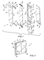
- an oven door is indicated overall by 1 and comprises a peripheral frame 2 of substantially rectangular shape, usually of metal, and a plurality of glazed surfaces which in Figure 1 are three in number and are indicated by the reference numerals from 3 to 5.
- the first surface 3 is the most outer surface with respect to the cavity of an oven (not shown) with which the door is associated
- the second surface 4 is the intermediate surface
- the third surface 5 is the inner surface, i.e. that which faces the said cavity.
- the door 1 is associated with a fixed structure of the oven (in which the said cavity is provided) by means of hinge members 7.
- the frame 2 for supporting the three glazed surfaces 3, 4 and 5 (these also being substantially rectangular) comprises a profile bar 10 of C cross-section presenting long sides 11 and 12 and short sides 13 and 14.
- the profile bar 10 of C cross-section has its lower side (side 12) undercut towards the oven exterior to enable the intermediate glass to be inserted (as will be clear from the ensuing description).
- From opposing sides of the frame 2 there therefore extend, perpendicular to these sides, walls 18 and 19 on which the surfaces 4 and 5 are arranged to rest.
- the glazed surface 4 is positioned between these walls within the frame 2.
- the first surface 3, however, has larger dimensions than those of the frame 2 and projects from this latter, as can be seen in Figure 2. Between the surfaces 4 and 5, maintained spaced apart by the walls 19, an air volume is present to reduce heat transfer from the third surface 5 to the second surface 4.
- the first glazed surface 3 is arranged to support a handle 20 fixed onto the outer face 3A of the surface 3 in any known manner.
- screws (not shown) or equivalent fixing members such as rivets etc.) passing through holes 22 formed in the glazed surface 3 fix the handle 20 to a metal element 23 positioned in correspondence with the inner face 3B of the surface 3 and fixed thereto by adhesive (for example two-component glue).
- the element 23 is positioned in correspondence with a first side 3K (which, despite of the perspective view, is of greater length) of the surface 3, a second element 24 similar to the first being positioned in correspondence with the second greater-length side 3H of this surface and being fixed to the face 3B of this latter by adhesive.
- the elements 23 and 24 comprise projections 28 to be secured, for example by elastic deformation, to the bent edges of the frame 2.
- the second glazed surface 4 cooperates with finned elements 30 positioned in correspondence with its opposing ends 31 and 32 (which, despite of the perspective view, are of greater length in Figure 1). These elements 30 are fixed to the surface 4 in any known manner, preferably by inserting said ends 31 and 32 into their seats 33; they are of thermoplastic material. The elements 30 are arranged to elastically react against the sides 11 and 12 of the frame 2, to absorb the deformations undergone by the glass during the use of the oven.
- the third glazed surface 5, facing the cavity interior, is secured to the frame 2 preferably by adhesive.
- the surface 5 comprises an end portion 5A of reduced transverse width L or presenting lateral bevels 35 enabling the lugs 36 of the hinge members 7 to be positioned on the side edges of the surface 5, to cooperate with hinge counter-members associated with the fixed structure of the oven.
- Each hinge member 7 is associated with a corresponding side 13 and 14 of the frame 2 by screws (or equivalent fixing members) cooperating with holes 38 and 39 provided in the side 13 and 14 and in an arm 7A of the member 7 (from which the lug 36 projects perpendicularly).
- Each hinge member 7 is also secured lowerly to the frame 2 by screws passing through suitable holes (not shown) in the frame and screwed into the body of the hinge member 7.
- the C-section profile bar 10 of the frame lowerly presents two undercut apertures for the insertion of the hinge members 7. Finally, one of the sides 11, 12, 13 or 14 is divided into two portions by a cut or aperture 40, as the profile bar 10 closes on itself in this region.
- the C-section profile bar is welded in this region before mounting the glass panels.
- the assembly of the door 1 is rapid and reliable.
- the glazed surface 5 is fixed to the frame 2 with two-component glue; the members 7 are then fixed to the frame 2 by two screws each; the second glazed surface 4 is then inserted into the frame 2, with the finned elements 30 being positioned to bear against the frame sides 11 and 12. This operation is facilitated by the deformability of said elements 30.
- the third glazed surface 3 (external) already provided with the handle 20 and the two metal elements 23 and 24 is then fixed to the frame 2.
- This fixing is achieved by inserting the upper metal element 23 into the frame 2 and then fixing the assembly by two screws which clamp the lower metal element 24 to the frame.
- These screws preferably of self-tapping type, are also screwed into the plastic finned element 30 of the inner glass panel 4.
- the door constructed in this manner also has a pleasant appearance in that the glazed surfaces are associated with the frame without visible support means being present for these surfaces.
Landscapes
- Engineering & Computer Science (AREA)
- Chemical & Material Sciences (AREA)
- Combustion & Propulsion (AREA)
- Mechanical Engineering (AREA)
- General Engineering & Computer Science (AREA)
- Electric Ovens (AREA)
- Securing Of Glass Panes Or The Like (AREA)
- Electric Stoves And Ranges (AREA)
Abstract
Description
Claims (10)
- An oven door (1) comprising a support frame (2) for a plurality of glazed surfaces (3, 4, 5), with the frame (2) there being associated hinge members (7) arranged to secure the door (1) to the oven in correspondence with a cooking cavity of this latter, characterised in that the frame (2) comprises a profile bar (10) of substantially C cross-section bent in the form of a rectangle, at least two glazed surfaces (3, 5) being rested on and secured to opposing faces of the frame (2).
- An oven door as claimed in claim 1, characterised in that a further glazed surface (4) is mounted in the interior of the frame (2).
- An oven door as claimed in claim 1, characterised in that the profile bar (10) of the frame (2) presents a joining region (40) on a greater-length side (12) of the frame.
- An oven door as claimed in claim 1, characterised in that on its outer face (3A) the first glazed surface (3) supports a handle (20).
- An oven door as claimed in claim 1, characterised in that the first glazed surface (3) supports on its inner face (3B), in correspondence with opposing sides (3K, 3H), coupling elements (23, 24) for securing said surface to the frame (2), said elements being fixed to the glazed surface (3) preferably by adhesive.
- An oven door as claimed in claims 4 and 5, characterised in that the handle (20) is fixed to the glazed surface (3) by screws or similar members which pass through holes (22) provided in said surface and are connected to one (23) of the coupling elements (23, 24).
- An oven door as claimed in claim 5, characterised in that each coupling element (23, 24) supports projections (28) which project towards the frame (2) and are coupled thereto.
- An oven door as claimed in claim 4, characterised in that the second glazed surface (4) internal to the frame (2) cooperates, at its opposing ends (31, 32), with deformable elements (30) arranged to act against opposing sides (11, 12) of the frame (2).
- An oven door as claimed in claim 8, characterised in that each deformable element (30) comprises a seat (33) arranged to contain a corresponding end (31, 32) of the second glazed surface (4).
- An oven door as claimed in claim 4, characterised in that the third glazed surface (5) presents an end portion (5A) provided with lateral bevels (35) which reduce its transverse width (L) relative to the remainder of said surface (5), hinge lugs (36) of the hinge members (7) being present at said bevels.
Applications Claiming Priority (2)
| Application Number | Priority Date | Filing Date | Title |
|---|---|---|---|
| ITMI20010307U | 2001-06-04 | ||
| ITMI20010307 ITMI20010307U1 (en) | 2001-06-04 | 2001-06-04 | DOOR FOR QUICK ASSEMBLY OVEN |
Publications (3)
| Publication Number | Publication Date |
|---|---|
| EP1265039A2 true EP1265039A2 (en) | 2002-12-11 |
| EP1265039A3 EP1265039A3 (en) | 2004-11-03 |
| EP1265039B1 EP1265039B1 (en) | 2007-01-10 |
Family
ID=11446887
Family Applications (1)
| Application Number | Title | Priority Date | Filing Date |
|---|---|---|---|
| EP20020011667 Expired - Lifetime EP1265039B1 (en) | 2001-06-04 | 2002-05-31 | Rapidly assembled oven door |
Country Status (4)
| Country | Link |
|---|---|
| EP (1) | EP1265039B1 (en) |
| DE (1) | DE60217441T2 (en) |
| ES (1) | ES2276870T3 (en) |
| IT (1) | ITMI20010307U1 (en) |
Cited By (2)
| Publication number | Priority date | Publication date | Assignee | Title |
|---|---|---|---|---|
| WO2009027444A3 (en) * | 2007-08-31 | 2009-07-09 | Arcelik As | A household appliance |
| US8839781B2 (en) | 2011-02-28 | 2014-09-23 | Mabe, S.A. De C.V. | Oven door |
Family Cites Families (3)
| Publication number | Priority date | Publication date | Assignee | Title |
|---|---|---|---|---|
| DE2036887A1 (en) * | 1970-07-24 | 1972-02-03 | Siemens Elektrogeraete Gmbh | Oven and roasting tube |
| US3877460A (en) * | 1974-02-01 | 1975-04-15 | Whirlpool Co | Oven door |
| DE19748196C2 (en) * | 1997-10-31 | 2001-04-05 | Schott Glas | Glazed door for a device with an increased interior temperature |
-
2001
- 2001-06-04 IT ITMI20010307 patent/ITMI20010307U1/en unknown
-
2002
- 2002-05-31 EP EP20020011667 patent/EP1265039B1/en not_active Expired - Lifetime
- 2002-05-31 ES ES02011667T patent/ES2276870T3/en not_active Expired - Lifetime
- 2002-05-31 DE DE2002617441 patent/DE60217441T2/en not_active Expired - Lifetime
Cited By (2)
| Publication number | Priority date | Publication date | Assignee | Title |
|---|---|---|---|---|
| WO2009027444A3 (en) * | 2007-08-31 | 2009-07-09 | Arcelik As | A household appliance |
| US8839781B2 (en) | 2011-02-28 | 2014-09-23 | Mabe, S.A. De C.V. | Oven door |
Also Published As
| Publication number | Publication date |
|---|---|
| EP1265039A3 (en) | 2004-11-03 |
| EP1265039B1 (en) | 2007-01-10 |
| ITMI20010307V0 (en) | 2001-06-04 |
| ITMI20010307U1 (en) | 2002-12-04 |
| DE60217441T2 (en) | 2007-10-18 |
| DE60217441D1 (en) | 2007-02-22 |
| ES2276870T3 (en) | 2007-07-01 |
Similar Documents
| Publication | Publication Date | Title |
|---|---|---|
| EP1265039B1 (en) | Rapidly assembled oven door | |
| KR101141576B1 (en) | A curtain wall bar with exterior insulation structure | |
| KR100678674B1 (en) | Front panel mounting structure of door for refrigerator | |
| KR200400146Y1 (en) | Insulation panel and union clip and an assembling structure thereof | |
| KR101156286B1 (en) | Door for refrigerator | |
| KR101671843B1 (en) | Side contact type skin plate for building | |
| EP1924812B1 (en) | A cooling device | |
| KR101692382B1 (en) | Curtain wall window having improved heat isolation | |
| JP2001073501A (en) | Panel and panel-attaching structure | |
| KR100777246B1 (en) | Partition frame structure for partition | |
| JP3159611B2 (en) | Front panel structure for refrigerators, etc. | |
| KR19990008187A (en) | Front frame attachment to housing | |
| JP2816798B2 (en) | Exterior panel | |
| KR20050095040A (en) | Panel for casing air conditioner | |
| JP2747884B2 (en) | Inner-joining frame connecting structure of external sliding window | |
| EP0893654A1 (en) | Oven door and method of assembly therefor | |
| JP2003179371A (en) | Rack door | |
| KR970003387Y1 (en) | Window frame mounting device of lightweight partition panel | |
| KR200168255Y1 (en) | The junction structure of door plates | |
| JP3679622B2 (en) | Glass run mounting structure | |
| KR100414643B1 (en) | Soundproof and fireproof door fixed with colored plate | |
| JP3847034B2 (en) | Vertical frame mounting bracket | |
| JP2510056Y2 (en) | Screen mounting device for hood | |
| KR101995661B1 (en) | Door for elevator and assembly method thereof | |
| JP3660958B2 (en) | Window frame mounting structure |
Legal Events
| Date | Code | Title | Description |
|---|---|---|---|
| PUAI | Public reference made under article 153(3) epc to a published international application that has entered the european phase |
Free format text: ORIGINAL CODE: 0009012 |
|
| AK | Designated contracting states |
Kind code of ref document: A2 Designated state(s): AT BE CH CY DE DK ES FI FR GB GR IE IT LI LU MC NL PT SE TR |
|
| AX | Request for extension of the european patent |
Free format text: AL;LT;LV;MK;RO;SI |
|
| PUAL | Search report despatched |
Free format text: ORIGINAL CODE: 0009013 |
|
| AK | Designated contracting states |
Kind code of ref document: A3 Designated state(s): AT BE CH CY DE DK ES FI FR GB GR IE IT LI LU MC NL PT SE TR |
|
| AX | Request for extension of the european patent |
Extension state: AL LT LV MK RO SI |
|
| 17P | Request for examination filed |
Effective date: 20050422 |
|
| AKX | Designation fees paid |
Designated state(s): DE ES FR GB IT SE |
|
| GRAP | Despatch of communication of intention to grant a patent |
Free format text: ORIGINAL CODE: EPIDOSNIGR1 |
|
| GRAS | Grant fee paid |
Free format text: ORIGINAL CODE: EPIDOSNIGR3 |
|
| GRAA | (expected) grant |
Free format text: ORIGINAL CODE: 0009210 |
|
| AK | Designated contracting states |
Kind code of ref document: B1 Designated state(s): DE ES FR GB IT SE |
|
| REG | Reference to a national code |
Ref country code: GB Ref legal event code: FG4D |
|
| REF | Corresponds to: |
Ref document number: 60217441 Country of ref document: DE Date of ref document: 20070222 Kind code of ref document: P |
|
| REG | Reference to a national code |
Ref country code: SE Ref legal event code: TRGR |
|
| REG | Reference to a national code |
Ref country code: ES Ref legal event code: FG2A Ref document number: 2276870 Country of ref document: ES Kind code of ref document: T3 |
|
| ET | Fr: translation filed | ||
| PLBE | No opposition filed within time limit |
Free format text: ORIGINAL CODE: 0009261 |
|
| STAA | Information on the status of an ep patent application or granted ep patent |
Free format text: STATUS: NO OPPOSITION FILED WITHIN TIME LIMIT |
|
| 26N | No opposition filed |
Effective date: 20071011 |
|
| PGFP | Annual fee paid to national office [announced via postgrant information from national office to epo] |
Ref country code: GB Payment date: 20140528 Year of fee payment: 13 |
|
| PGFP | Annual fee paid to national office [announced via postgrant information from national office to epo] |
Ref country code: ES Payment date: 20140411 Year of fee payment: 13 Ref country code: IT Payment date: 20140523 Year of fee payment: 13 Ref country code: FR Payment date: 20140509 Year of fee payment: 13 Ref country code: DE Payment date: 20140528 Year of fee payment: 13 Ref country code: SE Payment date: 20140513 Year of fee payment: 13 |
|
| REG | Reference to a national code |
Ref country code: DE Ref legal event code: R119 Ref document number: 60217441 Country of ref document: DE |
|
| GBPC | Gb: european patent ceased through non-payment of renewal fee |
Effective date: 20150531 |
|
| PG25 | Lapsed in a contracting state [announced via postgrant information from national office to epo] |
Ref country code: IT Free format text: LAPSE BECAUSE OF NON-PAYMENT OF DUE FEES Effective date: 20150531 |
|
| REG | Reference to a national code |
Ref country code: SE Ref legal event code: EUG |
|
| REG | Reference to a national code |
Ref country code: FR Ref legal event code: ST Effective date: 20160129 |
|
| PG25 | Lapsed in a contracting state [announced via postgrant information from national office to epo] |
Ref country code: SE Free format text: LAPSE BECAUSE OF NON-PAYMENT OF DUE FEES Effective date: 20150601 |
|
| PG25 | Lapsed in a contracting state [announced via postgrant information from national office to epo] |
Ref country code: DE Free format text: LAPSE BECAUSE OF NON-PAYMENT OF DUE FEES Effective date: 20151201 Ref country code: GB Free format text: LAPSE BECAUSE OF NON-PAYMENT OF DUE FEES Effective date: 20150531 |
|
| PG25 | Lapsed in a contracting state [announced via postgrant information from national office to epo] |
Ref country code: FR Free format text: LAPSE BECAUSE OF NON-PAYMENT OF DUE FEES Effective date: 20150601 |
|
| REG | Reference to a national code |
Ref country code: ES Ref legal event code: FD2A Effective date: 20170203 |
|
| PG25 | Lapsed in a contracting state [announced via postgrant information from national office to epo] |
Ref country code: ES Free format text: LAPSE BECAUSE OF NON-PAYMENT OF DUE FEES Effective date: 20150601 |