EP1264956A2 - Power actuating system for four-bar hinge articulated vehicle closure element - Google Patents
Power actuating system for four-bar hinge articulated vehicle closure element Download PDFInfo
- Publication number
- EP1264956A2 EP1264956A2 EP02076808A EP02076808A EP1264956A2 EP 1264956 A2 EP1264956 A2 EP 1264956A2 EP 02076808 A EP02076808 A EP 02076808A EP 02076808 A EP02076808 A EP 02076808A EP 1264956 A2 EP1264956 A2 EP 1264956A2
- Authority
- EP
- European Patent Office
- Prior art keywords
- hinge assembly
- closure element
- drive unit
- vehicle
- gear
- Prior art date
- Legal status (The legal status is an assumption and is not a legal conclusion. Google has not performed a legal analysis and makes no representation as to the accuracy of the status listed.)
- Withdrawn
Links
Images


Classifications
-
- E—FIXED CONSTRUCTIONS
- E05—LOCKS; KEYS; WINDOW OR DOOR FITTINGS; SAFES
- E05F—DEVICES FOR MOVING WINGS INTO OPEN OR CLOSED POSITION; CHECKS FOR WINGS; WING FITTINGS NOT OTHERWISE PROVIDED FOR, CONCERNED WITH THE FUNCTIONING OF THE WING
- E05F1/00—Closers or openers for wings, not otherwise provided for in this subclass
- E05F1/08—Closers or openers for wings, not otherwise provided for in this subclass spring-actuated, e.g. for horizontally sliding wings
- E05F1/10—Closers or openers for wings, not otherwise provided for in this subclass spring-actuated, e.g. for horizontally sliding wings for swinging wings, e.g. counterbalance
- E05F1/1091—Closers or openers for wings, not otherwise provided for in this subclass spring-actuated, e.g. for horizontally sliding wings for swinging wings, e.g. counterbalance with a gas spring
-
- E—FIXED CONSTRUCTIONS
- E05—LOCKS; KEYS; WINDOW OR DOOR FITTINGS; SAFES
- E05F—DEVICES FOR MOVING WINGS INTO OPEN OR CLOSED POSITION; CHECKS FOR WINGS; WING FITTINGS NOT OTHERWISE PROVIDED FOR, CONCERNED WITH THE FUNCTIONING OF THE WING
- E05F15/00—Power-operated mechanisms for wings
- E05F15/60—Power-operated mechanisms for wings using electrical actuators
- E05F15/603—Power-operated mechanisms for wings using electrical actuators using rotary electromotors
- E05F15/611—Power-operated mechanisms for wings using electrical actuators using rotary electromotors for swinging wings
- E05F15/63—Power-operated mechanisms for wings using electrical actuators using rotary electromotors for swinging wings operated by swinging arms
-
- E—FIXED CONSTRUCTIONS
- E05—LOCKS; KEYS; WINDOW OR DOOR FITTINGS; SAFES
- E05D—HINGES OR SUSPENSION DEVICES FOR DOORS, WINDOWS OR WINGS
- E05D3/00—Hinges with pins
- E05D3/06—Hinges with pins with two or more pins
- E05D3/14—Hinges with pins with two or more pins with four parallel pins and two arms
- E05D3/145—Hinges with pins with two or more pins with four parallel pins and two arms specially adapted for vehicles
-
- E—FIXED CONSTRUCTIONS
- E05—LOCKS; KEYS; WINDOW OR DOOR FITTINGS; SAFES
- E05F—DEVICES FOR MOVING WINGS INTO OPEN OR CLOSED POSITION; CHECKS FOR WINGS; WING FITTINGS NOT OTHERWISE PROVIDED FOR, CONCERNED WITH THE FUNCTIONING OF THE WING
- E05F1/00—Closers or openers for wings, not otherwise provided for in this subclass
- E05F1/08—Closers or openers for wings, not otherwise provided for in this subclass spring-actuated, e.g. for horizontally sliding wings
- E05F1/10—Closers or openers for wings, not otherwise provided for in this subclass spring-actuated, e.g. for horizontally sliding wings for swinging wings, e.g. counterbalance
- E05F1/12—Mechanisms in the shape of hinges or pivots, operated by springs
- E05F1/1292—Mechanisms in the shape of hinges or pivots, operated by springs with a gas spring
-
- E—FIXED CONSTRUCTIONS
- E05—LOCKS; KEYS; WINDOW OR DOOR FITTINGS; SAFES
- E05Y—INDEXING SCHEME RELATING TO HINGES OR OTHER SUSPENSION DEVICES FOR DOORS, WINDOWS OR WINGS AND DEVICES FOR MOVING WINGS INTO OPEN OR CLOSED POSITION, CHECKS FOR WINGS AND WING FITTINGS NOT OTHERWISE PROVIDED FOR, CONCERNED WITH THE FUNCTIONING OF THE WING
- E05Y2201/00—Constructional elements; Accessories therefore
- E05Y2201/20—Brakes; Disengaging means, e.g. clutches; Holders, e.g. locks; Stops; Accessories therefore
- E05Y2201/214—Disengaging means
- E05Y2201/216—Clutches
-
- E—FIXED CONSTRUCTIONS
- E05—LOCKS; KEYS; WINDOW OR DOOR FITTINGS; SAFES
- E05Y—INDEXING SCHEME RELATING TO HINGES OR OTHER SUSPENSION DEVICES FOR DOORS, WINDOWS OR WINGS AND DEVICES FOR MOVING WINGS INTO OPEN OR CLOSED POSITION, CHECKS FOR WINGS AND WING FITTINGS NOT OTHERWISE PROVIDED FOR, CONCERNED WITH THE FUNCTIONING OF THE WING
- E05Y2201/00—Constructional elements; Accessories therefore
- E05Y2201/20—Brakes; Disengaging means, e.g. clutches; Holders, e.g. locks; Stops; Accessories therefore
- E05Y2201/23—Actuation thereof
- E05Y2201/246—Actuation thereof by motors, magnets, springs or weights
-
- E—FIXED CONSTRUCTIONS
- E05—LOCKS; KEYS; WINDOW OR DOOR FITTINGS; SAFES
- E05Y—INDEXING SCHEME RELATING TO HINGES OR OTHER SUSPENSION DEVICES FOR DOORS, WINDOWS OR WINGS AND DEVICES FOR MOVING WINGS INTO OPEN OR CLOSED POSITION, CHECKS FOR WINGS AND WING FITTINGS NOT OTHERWISE PROVIDED FOR, CONCERNED WITH THE FUNCTIONING OF THE WING
- E05Y2201/00—Constructional elements; Accessories therefore
- E05Y2201/40—Motors; Magnets; Springs; Weights; Accessories therefore
- E05Y2201/404—Motors; Magnets; Springs; Weights; Accessories therefore characterised by the function
- E05Y2201/416—Motors; Magnets; Springs; Weights; Accessories therefore characterised by the function for counterbalancing
-
- E—FIXED CONSTRUCTIONS
- E05—LOCKS; KEYS; WINDOW OR DOOR FITTINGS; SAFES
- E05Y—INDEXING SCHEME RELATING TO HINGES OR OTHER SUSPENSION DEVICES FOR DOORS, WINDOWS OR WINGS AND DEVICES FOR MOVING WINGS INTO OPEN OR CLOSED POSITION, CHECKS FOR WINGS AND WING FITTINGS NOT OTHERWISE PROVIDED FOR, CONCERNED WITH THE FUNCTIONING OF THE WING
- E05Y2201/00—Constructional elements; Accessories therefore
- E05Y2201/40—Motors; Magnets; Springs; Weights; Accessories therefore
- E05Y2201/46—Magnets
- E05Y2201/462—Electromagnets
-
- E—FIXED CONSTRUCTIONS
- E05—LOCKS; KEYS; WINDOW OR DOOR FITTINGS; SAFES
- E05Y—INDEXING SCHEME RELATING TO HINGES OR OTHER SUSPENSION DEVICES FOR DOORS, WINDOWS OR WINGS AND DEVICES FOR MOVING WINGS INTO OPEN OR CLOSED POSITION, CHECKS FOR WINGS AND WING FITTINGS NOT OTHERWISE PROVIDED FOR, CONCERNED WITH THE FUNCTIONING OF THE WING
- E05Y2900/00—Application of doors, windows, wings or fittings thereof
- E05Y2900/50—Application of doors, windows, wings or fittings thereof for vehicles
- E05Y2900/53—Application of doors, windows, wings or fittings thereof for vehicles characterised by the type of wing
- E05Y2900/548—Trunk lids
Definitions
- This invention relates to power operation of a pivotal vehicle closure element and more particularly to power operation thereof by means of a motor driven four-bar hinge articulation support.
- hoods and deck lids Certain smaller size passenger vehicles are provided with four-bar hinge articulated support in order to provide a special travel path of the movable hood or deck lid during its motion between fully open and fully closed position in order to accommodate clearance of various body obstructions.
- Such four-bar hinge articulation also increases the angular range of pivotable travel of the closure element so that the same is out of the way of the personnel gaining access to or from the vehicle compartment closed by the element.
- the hinge is located on the weather side of the compartment closure weather seal, an adverse environment for locating an electro-mechanical drive unit for powering the flange. Therefore, a need continues to exist for relatively non-complex, weatherproof, compact, competitive and reliable means of power operation for a four-bar hinge articulation of the vehicle closure element which also readily permits manual actuation thereof in the normal state with the power drive de-energized.
- an improved four-bar hinge articulation of a pivotable vehicle closure element which is capable of power opening and closing the closure element by remote control actuation, that is essentially invisible to the customer or vehicle user with respect to the power drive components of the system, that can be overridden by manual force applied to open and close the closure element, that provides a compact power drive system for the four-bar hinge, that is capable of operation with standard obstacle detection software and which is rugged, compact, economical in construction and installation and in which the electrical components and drive system are shielded from exterior weather by mounting in a normally unused space within a weather sealed compartment of the vehicle.
- this invention accomplishes one or more of the foregoing objects by providing an improved four-bar hinge assembly for attaching a pivotable vehicle closure element to the vehicle body in which the control link of the four-bar linkage has its usual vehicle-mounted pivot pin replaced by the rotatably driven output shaft of a power drive mechanism.
- the output shaft is rigidly and directly coupled to the control link to impart swinging motion to the same to thereby power actuate the four-bar linkage in order to pivot the closure element for travel between open and closed positions.
- the four-bar linkage hinge elements are located in their usual position on the weather side of the vehicle body components.
- the pivot support/drive shaft extends through the vehicle sheet metal separating the weather side from the weather sealed compartment closed by the vehicle closure element so that all components of the electromagnetic drive system are mounted within the weather sealed and preferably normally unused compartment space of the vehicle accessed by the vehicle closure element.
- the power drive unit preferably comprises a completely encased gear reduction transmission driven by a conventional, reversible electric motor and associated electromagnetic clutch operable remotely via a control circuit of conventional construction.
- Preferably telescopic gas spring counterbalance elements are also provided to reduce power requirements and to enable manual operation when desired.
- Limit switches may be provided to de-energize the electric motor and electromagnetic clutch at the end limits of closure element travel, as well as to sense obstructions to travel to de-energize the system. The electromagnetic clutch disengages when de-energized so that the closure element can be moved manually in the event of power failure.
- FIG. 1 illustrates fragmentarily the rear portion of an automotive passenger vehicle 20 having the usual trunk cargo compartment 22 at the vehicle aft end.
- a pivotable vehicle closure element in the form of a conventional trunk deck lid 24 is pivotally attached to the starboard and port sidewalls 26 and 28 of the sheet metal vehicle body components forming the trunk compartment rain gutter 48 by starboard and port four-bar hinge assemblies 30 and 32 that are located on the weather side of the trunk compartment weather sealing system.
- Each hinge assembly 30, 32 is located near the rear window 34 of the passenger compartment of vehicle 20 so that deck lid 24 swings between and to the open position thereof shown in FIGS. 1-5 and the fully closed position shown in FIG. 6.
- Conventional starboard and port telescopic counterbalancing gas springs 36 and 38 are operably coupled between deck lid 24 and rain gutter walls 26 and 28 respectively to provide suitable counterbalancing forces to assist in the opening and closing of deck lid 24.
- hinge assembly 32 is of conventional construction and comprises a deck lid bracket 40 in the form of an angle plate having one flange 42 attached to the interior side of deck lid 24 and another flange 44 protruding therefrom. Hinge assembly 32 further includes a mounting bracket 46 riveted or otherwise suitably secured to the sidewall 28 of the body trunk sheet metal that defines the outboard wall of the rain gutter 48 surrounding trunk opening 22. The inner wall of rain gutter 48 is defined by the usual upturned sheet metal lip 50.
- Deck lid bracket 40 is attached to body mounting bracket 46 for swinging movement between the closed position shown in FIG. 6 and the open position shown in FIGS. 1-5 by hinge link 52 and control link 54 of the slave linkage assembly 32.
- Hinge link 52 is pivotally attached at one end to deck lid bracket 40 by a first pivot pin 56 and at the other end to mounting bracket 46 by a second pivot pin 58.
- Control link 54 is pivotally attached at one end to deck lid bracket 40 by a third pivot pin 60 that is spaced from pivot pin 56 and at its opposite end to mounting bracket 46 by a fourth pivot pin 62 that is spaced from pivot pin 58.
- At least one of the two hinge assemblies 30 and 32 is directly power operated.
- starboard four-bar hinge assembly 30 is modified to become a power operated four-bar hinge assembly. Basically, this is accomplished pursuant to the invention by converting the idler pivot connection of pin 62 of hinge assembly 32 into a torque transmitting pivot support construction in hinge assembly 30.
- Hinge assembly 30 thus also constitutes a deck lid bracket 70 (which is the mirror image of bracket 40), a main hinge link 72 (which is the mirror image of hinge link 52) connected at its opposite ends by a pivot pin 74 to bracket 70 and by pivot pin 76 to a shortened (and thus modified) mounting bracket 78 fixed to rain gutter sidewall 26.
- a control link 80 of hinge assembly 30 is connected at one of its opposite ends by a pivot pin 82 to bracket 70, and pin 82 is spaced from pin 74 in the manner of the spacing of pivot pins 56 and 60.
- control link 80 is modified from control link 54 in having a heavy duty connector lug arm 84 welded to an upper section 86 of link 80 and cocked at an angle thereto (FIGS. 2, 5 and 6) in manner of the angular relationship of the upper and lower canted sections 88 and 90 of control link 54 of hinge assembly 32 (FIG. 4).
- the lower end of lug 84 is mounted on and keyed for rotation with a combination drive shaft and pivot pin journal support shaft 90 that protrudes through outboard rain gutter wall 26, and described in more detail hereinafter in conjunction with FIGS. 7 and 9.
- Pivot power output shaft 90 is bi-directionally rotatably power driven by an electro-mechanical drive unit 100 also provided in accordance with a further principal feature of the present invention, to thereby power actuate hinge assembly 30 through its operable angular range of linkage articulation to move deck lid 24 throughout its full range of angular travel between open and closed positions.
- the non-powered hinge assembly 32 is slave driven in like manner.
- drive unit 100 includes a reversible electric motor 102 of conventional commercially available construction that is attached to and supported by a housing of a conventional commercially available electromagnetic clutch subassembly 104.
- a bracket plate 106 (FIG. 9) of clutch 104 attaches to a motor mount ring 108 that in turn attaches to a housing plate part 110 specially provided in accordance with the invention.
- the electromagnetic clutch component 104 includes a worm gear (not seen) on the output shaft of motor 102 that drives a helical gear (not seen) within the clutch housing and that is clutch coupled to rotatably and bi-directionally drive an output pinion gear 112.
- An optical sensor disk 114 is also mounted between bracket 106 and pinion gear 112 and is rotatably driven in unison with pinion 112.
- Pinion 112 drivingly meshes with the teeth of enlarged diameter spur gear 116 that is rotatably journaled in a cavity 118 of housing 110 located on the side opposite motor/clutch unit 102/104.
- Spur gear 116 is a compound gear having a small pinion 120 (indicated schematically via broken lines in FIG. 9) attached thereto on its underside for rotation therewith.
- the teeth of pinion 120 of compound gear 116 drivingly mesh with the spur gear teeth of a sector gear 122 that seats in a housing cavity 124 opening to housing cavity 118 and having sufficient angular extent to accommodate the pivotal angular working range of sector gear 122, i.e., the range of angular travel of control link 80 between the lid-open and lid-closed positions of FIGS. 5 and 6 respectively.
- a hub (not shown) on the underside of sector gear 122 is journaled in a bore 126 of housing 110.
- Output sector 122 has fixed to its upper side (as viewed in FIG. 9) for bi-directional rotation therewith output shaft 90 that extends coaxially with the center of rotation of sector 122.
- the largest diameter primary shank portion 130 of shaft 90 extends through an registering opening in a cover 132 of drive unit 100, and is journaled in a pass-through bearing 134 in turn received in a bore 136 of a mounting bracket 138 welded to the outer face of cover 132.
- a reduced diameter secondary shank portion 140 of shaft 90 is joumaled in an annular seal housing 142 fixed to an outer seal plate 144.
- shank 140 remote from sector 122 is provided with a pair of flats 146 that drivingly register with flatted portions of the through-bore of lug arm 84 of control driving link 80.
- the distal end 148 of shaft 128 is threaded to receive a locking nut 150 thereon, as shown in FIG. 2.
- outer seal plate 144 is shown inverted in FIG. 9 relative to the remaining parts of FIG. 9 and hence the side of plate 144 that is seen in FIGS. 2, 5, 6 and 7 is the side hidden from view in FIG. 9.
- the electro-mechanical drive unit 100 is mounted in the weather sealed and normally unused space available in the trunk compartment 22 adjacent the vehicle quarter panel and outboard of gutter wall 26, as best seen in FIGS. 1, 2 and 3.
- the vehicle body mounting platform for supporting drive unit 100 is the outer sidewall 26 of rain gutter 48.
- a flange 160 of mounting bracket 138 (FIG. 9) bears against the outboard surface of gutter wall 26, and a surface 162 of seal plate 144 bears against the inboard surface of gutter wall 26.
- Suitable openings are provided in wall 26 to accommodate a pair of mounting bolts 164 and 166 (best seen in FIG. 2) that pass through an associated pair of openings 168 and 170 (FIG.
- a pair of Allen head socket bolts 172 and 174 pass through associated openings in plate 144 and threadably register with threaded sockets in mounting flange 160 to thereby clamp flange 160 against the outboard surface of wall 28.
- a suitable weather sealing bedding compound is applied to the abutting surface of plate 144 and wall 28.
- Suitable seals are also provided for pass-through bolts 172 and 174.
- O-ring seals (not seen) are provided in the pass-through seal housing 142 that sealably engage shaft shank 140.
- Unit 100 as well as the electrical leads to motor 102, are also tucked away in the uppermost quarter panel space and thus also protected from bumping abuse from loading and unloading objects into and out of trunk space 22, as well as unlikely being bumped by cargo therein during vehicle travel.
- trunk deck lid 24 is swung from the closed position of FIG. 6 to the open position of PIGS. 1-5 by energizing electric motor 102 and electromagnetic clutch 104 to generate drive torque that is multiplied via gear reduction to thereby rotate sector gear 122 and hence output shaft 90 so as directly to swing hinge link 80 clockwise about 90° from its position in FIG. 6 to that of FIG. 5.
- This power actuation of drive hinge assembly 30 and slave hinge assembly 32, coupled with their four-bar linkage articulation causes trunk deck lid 24 to be moved slightly aft away from rear window 34 as the same is tilted upwardly and pivoted counterclockwise as viewed in FIGS. 5 and 6.
- lid 24 is thus raised away from the vehicle body tail section 180 as it moves to the fully open position shown in FIG. 1.
- the slave hinge assembly 32 on the port side of vehicle 20, operates in the same way at the same time so that trunk deck lid 24 swings open in a balanced manner, gas springs 36 and 38 providing counterbalancing forces to assist this motion.
- a conventional limit switch or the like is actuated to de-energize electric motor 102 and electromagnetic clutch 104.
- Deck lid 24 is closed by reversing electric motor 102 and engaging clutch 104 so that sector gear 122 is driven back to the position that establishes the relationship of the parts shown in FIG. 6.
- another conventional limit switch is likewise actuated to de-energize electric motor 102 and electromagnetic clutch 104.
- Electromagnetic clutch 104 is operable to disengage when de-energized so that deck lid 24 can be moved manually in the event of a power failure, or when access to the remote controls is not convenient or available.
- conventional obstruction sensing circuitry is preferably employed to de-energize electromagnetic clutch in the event deck lid 24 strikes an obstruction during travel between open and closed positions.
- the power operating system described above employing a single drive unit 100, with the assist of counterbalancing forces from gas springs 36 and 38, is typically adequate for smaller vehicles and deck lids 24 that are lighter in weight.
- two mirror-image drive units may be provided, one on port and one on starboard, constructed and installed in the manner as the single starboard unit 100 described hereinabove, so that both four-bar hinge assemblies 30 and 32 are directly power actuated.
- the powered deck lid actuator of the invention amply fulfills one or more of the aforestated objects and provides many novel features and advantages over the prior art.
- the power actuating system of the invention is compact, rugged, fully weather-protected, does not require any exposed cables or rack and pinion drives, has a fully encased power train and drive unit 100 that provides high force multiplication with internal gear reduction, can be lubricated permanently without danger of lubricant leakage, and is economical to manufacture and install and efficient in operation due to the direct mechanical rotary drive connection between the output shaft 90 and control link 80 of the four-bar hinge assembly 30.
- the clutch contacts (not seen) of the electrical control circuit are readily housed within space available in the cover 132.
- the optical sensor disk 114 is well protected in housing cover 130 that in turn provides a mount for a conventional optical sensor cooperating with disk 114 and the remote control computer program of conventional computer control circuitry.
- port side mounting bracket 46 is shown in FIG. 4 and described as a separate piece, and in this particular instance is a pre-existing part on vehicle 20, it should be understood that a portion of the sidewall 26 of rain gutter 48 can serve as the mounting bracket with hinge link 72 pivotally connected directly to the sidewall to form the four-bar linkage or hinge.
- the deck lid bracket 70 can be an integrated part of the deck lid rather than a separate piece as shown and described hereinabove.
Abstract
Description
- This invention relates to power operation of a pivotal vehicle closure element and more particularly to power operation thereof by means of a motor driven four-bar hinge articulation support.
- Power operation of vehicle closure elements such as doors, hoods, liftgates, tailgates and deck lids is, in principle, known in the prior art. Convenience and ergonomic related benefits associated with providing power operation of closure elements are readily apparent. A growing marketplace trend toward preferring such convenience, and in certain cases, necessary features exist. With respect to hoods and deck lids, certain smaller size passenger vehicles are provided with four-bar hinge articulated support in order to provide a special travel path of the movable hood or deck lid during its motion between fully open and fully closed position in order to accommodate clearance of various body obstructions. Such four-bar hinge articulation also increases the angular range of pivotable travel of the closure element so that the same is out of the way of the personnel gaining access to or from the vehicle compartment closed by the element. In some vehicles the hinge is located on the weather side of the compartment closure weather seal, an adverse environment for locating an electro-mechanical drive unit for powering the flange. Therefore, a need continues to exist for relatively non-complex, weatherproof, compact, competitive and reliable means of power operation for a four-bar hinge articulation of the vehicle closure element which also readily permits manual actuation thereof in the normal state with the power drive de-energized.
- Accordingly, among the objects of the invention are to provide an improved four-bar hinge articulation of a pivotable vehicle closure element which is capable of power opening and closing the closure element by remote control actuation, that is essentially invisible to the customer or vehicle user with respect to the power drive components of the system, that can be overridden by manual force applied to open and close the closure element, that provides a compact power drive system for the four-bar hinge, that is capable of operation with standard obstacle detection software and which is rugged, compact, economical in construction and installation and in which the electrical components and drive system are shielded from exterior weather by mounting in a normally unused space within a weather sealed compartment of the vehicle.
- In general, and by way of summary description and not by way of limitation, this invention accomplishes one or more of the foregoing objects by providing an improved four-bar hinge assembly for attaching a pivotable vehicle closure element to the vehicle body in which the control link of the four-bar linkage has its usual vehicle-mounted pivot pin replaced by the rotatably driven output shaft of a power drive mechanism. The output shaft is rigidly and directly coupled to the control link to impart swinging motion to the same to thereby power actuate the four-bar linkage in order to pivot the closure element for travel between open and closed positions. The four-bar linkage hinge elements are located in their usual position on the weather side of the vehicle body components. However, the pivot support/drive shaft extends through the vehicle sheet metal separating the weather side from the weather sealed compartment closed by the vehicle closure element so that all components of the electromagnetic drive system are mounted within the weather sealed and preferably normally unused compartment space of the vehicle accessed by the vehicle closure element.
The power drive unit preferably comprises a completely encased gear reduction transmission driven by a conventional, reversible electric motor and associated electromagnetic clutch operable remotely via a control circuit of conventional construction. Preferably telescopic gas spring counterbalance elements are also provided to reduce power requirements and to enable manual operation when desired. Limit switches may be provided to de-energize the electric motor and electromagnetic clutch at the end limits of closure element travel, as well as to sense obstructions to travel to de-energize the system. The electromagnetic clutch disengages when de-energized so that the closure element can be moved manually in the event of power failure. - The foregoing as well as other objects, features and advantages of the present invention will be come apparent from the following detailed description, appended claims and accompanying drawings (which are to engineering scale unless otherwise indicated), wherein:
- FIG. 1 is a fragmentary perspective view of the rear portion of an automotive passenger vehicle having a rear trunk deck lid shown in open position and attached by a power actuated four-bar hinge construction of the invention to the weather side of the trunk cargo opening.
- FIG. 2 is a fragmentary perspective view of the starboard side four-bar linkage and associated power drive components of the invention with the deck lid shown in fully open position as viewed from the port side of the vehicle looking down into the starboard side of the trunk compartment.
- FIG. 3 is a fragmentary perspective view of the starboard side components of FIG. 2 but viewed from the port side at a lower elevation (than that of FIG. 2) and from within the trunk compartment.
- FIG. 4 is a fragmentary perspective view of the conventional four-bar hinge assembly and associated gas spring counterbalance provided on the port side of the vehicle, and operated as an unpowered four-bar hinge slave articulation.
- FIGS. 5 and 6 are side elevational views of the starboard side hinge and drive components of FIGS. 2 and 3 and respectively illustrating the fully opened and fully closed position of the trunk deck lid and associated four-bar hinge and counterbalance components.
- FIG. 7 is a view of the port side of the electrical mechanical drive unit and associated vehicle body mounting hardware for the same shown by themselves apart from the vehicle.
- FIG. 8 is a side elevational view of the starboard side of the hinge drive unit of FIG. 7.
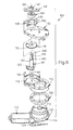
- FIG. 9 is an exploded perspective view of the hinge electro-mechanical drive unit seen in FIGS. 1-3 and 5-8.
-
- Referring in more detail to the accompanying drawings, FIG. 1 illustrates fragmentarily the rear portion of an
automotive passenger vehicle 20 having the usualtrunk cargo compartment 22 at the vehicle aft end. A pivotable vehicle closure element in the form of a conventionaltrunk deck lid 24 is pivotally attached to the starboard andport sidewalls compartment rain gutter 48 by starboard and port four-bar hinge assemblies hinge assembly rear window 34 of the passenger compartment ofvehicle 20 so thatdeck lid 24 swings between and to the open position thereof shown in FIGS. 1-5 and the fully closed position shown in FIG. 6. Conventional starboard and port telescopiccounterbalancing gas springs deck lid 24 andrain gutter walls deck lid 24. - Referring first to the port side slave four-
bar hinge assembly 32 shown in FIG. 1 and in greater detail in FIG. 4,hinge assembly 32 is of conventional construction and comprises adeck lid bracket 40 in the form of an angle plate having oneflange 42 attached to the interior side ofdeck lid 24 and anotherflange 44 protruding therefrom.Hinge assembly 32 further includes amounting bracket 46 riveted or otherwise suitably secured to thesidewall 28 of the body trunk sheet metal that defines the outboard wall of therain gutter 48 surrounding trunk opening 22. The inner wall ofrain gutter 48 is defined by the usual upturnedsheet metal lip 50. -
Deck lid bracket 40 is attached tobody mounting bracket 46 for swinging movement between the closed position shown in FIG. 6 and the open position shown in FIGS. 1-5 byhinge link 52 andcontrol link 54 of theslave linkage assembly 32. Hingelink 52 is pivotally attached at one end todeck lid bracket 40 by afirst pivot pin 56 and at the other end to mountingbracket 46 by asecond pivot pin 58.Control link 54 is pivotally attached at one end todeck lid bracket 40 by athird pivot pin 60 that is spaced frompivot pin 56 and at its opposite end to mountingbracket 46 by afourth pivot pin 62 that is spaced frompivot pin 58. Thus,deck lid bracket 40, andlinks deck lid bracket 40 to mountingbracket 22 for swinging movement ofdeck lid 24, constitute a four-bar linkage type orhinge assembly 32 that are exposed to ambient weather conditions. - In accordance with one principal feature of the present invention, at least one of the two
hinge assemblies bar hinge assembly 30 is modified to become a power operated four-bar hinge assembly. Basically, this is accomplished pursuant to the invention by converting the idler pivot connection ofpin 62 ofhinge assembly 32 into a torque transmitting pivot support construction inhinge assembly 30.
Hinge assembly 30 thus also constitutes a deck lid bracket 70 (which is the mirror image of bracket 40), a main hinge link 72 (which is the mirror image of hinge link 52) connected at its opposite ends by apivot pin 74 tobracket 70 and bypivot pin 76 to a shortened (and thus modified)mounting bracket 78 fixed torain gutter sidewall 26. Acontrol link 80 ofhinge assembly 30 is connected at one of its opposite ends by apivot pin 82 tobracket 70, andpin 82 is spaced frompin 74 in the manner of the spacing ofpivot pins - The principle difference between
slave hinge assembly 32 and poweredhinge assembly 30 in the vehicle-mounted end is thatcontrol link 80 is modified fromcontrol link 54 in having a heavy dutyconnector lug arm 84 welded to anupper section 86 oflink 80 and cocked at an angle thereto (FIGS. 2, 5 and 6) in manner of the angular relationship of the upper and lower cantedsections control link 54 of hinge assembly 32 (FIG. 4). The lower end oflug 84 is mounted on and keyed for rotation with a combination drive shaft and pivot pinjournal support shaft 90 that protrudes through outboardrain gutter wall 26, and described in more detail hereinafter in conjunction with FIGS. 7 and 9. - Pivot
power output shaft 90 is bi-directionally rotatably power driven by an electro-mechanical drive unit 100 also provided in accordance with a further principal feature of the present invention, to thereby power actuatehinge assembly 30 through its operable angular range of linkage articulation to movedeck lid 24 throughout its full range of angular travel between open and closed positions. Likewise, by forces transmitted viadeck lid 24, the non-poweredhinge assembly 32 is slave driven in like manner. - Referring to FIGS. 7, 8 and 9,
drive unit 100 includes a reversibleelectric motor 102 of conventional commercially available construction that is attached to and supported by a housing of a conventional commercially availableelectromagnetic clutch subassembly 104. A bracket plate 106 (FIG. 9) ofclutch 104 attaches to amotor mount ring 108 that in turn attaches to ahousing plate part 110 specially provided in accordance with the invention. Theelectromagnetic clutch component 104 includes a worm gear (not seen) on the output shaft ofmotor 102 that drives a helical gear (not seen) within the clutch housing and that is clutch coupled to rotatably and bi-directionally drive anoutput pinion gear 112. Anoptical sensor disk 114 is also mounted betweenbracket 106 andpinion gear 112 and is rotatably driven in unison withpinion 112. - Pinion 112 drivingly meshes with the teeth of enlarged
diameter spur gear 116 that is rotatably journaled in acavity 118 ofhousing 110 located on the side opposite motor/clutch unit 102/104.Spur gear 116 is a compound gear having a small pinion 120 (indicated schematically via broken lines in FIG. 9) attached thereto on its underside for rotation therewith. The teeth ofpinion 120 ofcompound gear 116 drivingly mesh with the spur gear teeth of asector gear 122 that seats in ahousing cavity 124 opening tohousing cavity 118 and having sufficient angular extent to accommodate the pivotal angular working range ofsector gear 122, i.e., the range of angular travel ofcontrol link 80 between the lid-open and lid-closed positions of FIGS. 5 and 6 respectively. A hub (not shown) on the underside ofsector gear 122 is journaled in a bore 126 ofhousing 110. -
Output sector 122 has fixed to its upper side (as viewed in FIG. 9) for bi-directional rotation therewithoutput shaft 90 that extends coaxially with the center of rotation ofsector 122. The largest diameterprimary shank portion 130 ofshaft 90 extends through an registering opening in acover 132 ofdrive unit 100, and is journaled in a pass-through bearing 134 in turn received in abore 136 of amounting bracket 138 welded to the outer face ofcover 132. A reduced diametersecondary shank portion 140 ofshaft 90 is joumaled in anannular seal housing 142 fixed to anouter seal plate 144.
The end ofshank 140 remote fromsector 122 is provided with a pair offlats 146 that drivingly register with flatted portions of the through-bore oflug arm 84 ofcontrol driving link 80. Thedistal end 148 of shaft 128 is threaded to receive alocking nut 150 thereon, as shown in FIG. 2. Note thatouter seal plate 144 is shown inverted in FIG. 9 relative to the remaining parts of FIG. 9 and hence the side ofplate 144 that is seen in FIGS. 2, 5, 6 and 7 is the side hidden from view in FIG. 9. - In accordance with a further feature of the present invention, the electro-
mechanical drive unit 100 is mounted in the weather sealed and normally unused space available in thetrunk compartment 22 adjacent the vehicle quarter panel and outboard ofgutter wall 26, as best seen in FIGS. 1, 2 and 3. The vehicle body mounting platform for supportingdrive unit 100 is theouter sidewall 26 ofrain gutter 48. When so mounted, aflange 160 of mounting bracket 138 (FIG. 9) bears against the outboard surface ofgutter wall 26, and asurface 162 ofseal plate 144 bears against the inboard surface ofgutter wall 26. Suitable openings are provided inwall 26 to accommodate a pair of mounting bolts 164 and 166 (best seen in FIG. 2) that pass through an associated pair ofopenings 168 and 170 (FIG. 7) inplate 144 to thereby fastenplate 144 togutter wall 26. A pair of Allenhead socket bolts plate 144 and threadably register with threaded sockets in mountingflange 160 to thereby clampflange 160 against the outboard surface ofwall 28. - In the mounting of
plate 144 to wall 28, a suitable weather sealing bedding compound is applied to the abutting surface ofplate 144 andwall 28. Suitable seals are also provided for pass-throughbolts seal housing 142 that sealably engageshaft shank 140. Hence, water collecting inrain gutter 48 cannot leak through to the interior oftrunk compartment 22 via the mounting hardware nor output shaft journals forunit 100. Thus,drive unit 100 is protected from rain and wash water, snow, ice and dirt.Unit 100, as well as the electrical leads tomotor 102, are also tucked away in the uppermost quarter panel space and thus also protected from bumping abuse from loading and unloading objects into and out oftrunk space 22, as well as unlikely being bumped by cargo therein during vehicle travel. - In operation,
trunk deck lid 24 is swung from the closed position of FIG. 6 to the open position of PIGS. 1-5 by energizingelectric motor 102 and electromagnetic clutch 104 to generate drive torque that is multiplied via gear reduction to thereby rotatesector gear 122 and henceoutput shaft 90 so as directly toswing hinge link 80 clockwise about 90° from its position in FIG. 6 to that of FIG. 5. This power actuation ofdrive hinge assembly 30 andslave hinge assembly 32, coupled with their four-bar linkage articulation, causestrunk deck lid 24 to be moved slightly aft away fromrear window 34 as the same is tilted upwardly and pivoted counterclockwise as viewed in FIGS. 5 and 6. The aft end oflid 24 is thus raised away from the vehiclebody tail section 180 as it moves to the fully open position shown in FIG. 1. Theslave hinge assembly 32, on the port side ofvehicle 20, operates in the same way at the same time so thattrunk deck lid 24 swings open in a balanced manner, gas springs 36 and 38 providing counterbalancing forces to assist this motion. - It will thus be seen that the four-
bar hinge assemblies trunk space 22 control movement oftrunk deck lid 24 in the same manner as previously provided solely for manual operation. Hence, essentially very little redesign or modification of the existing four-bar hinge assemblies is required to accomplish remotely controlled power assist operation in accordance with the invention. - When
deck lid 24 is fully opened, a conventional limit switch or the like is actuated to de-energizeelectric motor 102 andelectromagnetic clutch 104.Deck lid 24 is closed by reversingelectric motor 102 and engaging clutch 104 so thatsector gear 122 is driven back to the position that establishes the relationship of the parts shown in FIG. 6. Whendeck lid 24 is fully closed another conventional limit switch is likewise actuated to de-energizeelectric motor 102 andelectromagnetic clutch 104.Electromagnetic clutch 104 is operable to disengage when de-energized so thatdeck lid 24 can be moved manually in the event of a power failure, or when access to the remote controls is not convenient or available. Likewise, conventional obstruction sensing circuitry is preferably employed to de-energize electromagnetic clutch in theevent deck lid 24 strikes an obstruction during travel between open and closed positions. - The power operating system described above employing a
single drive unit 100, with the assist of counterbalancing forces from gas springs 36 and 38, is typically adequate for smaller vehicles anddeck lids 24 that are lighter in weight. However, if more power and/or power-balanced operation is desired, two mirror-image drive units may be provided, one on port and one on starboard, constructed and installed in the manner as thesingle starboard unit 100 described hereinabove, so that both four-bar hinge assemblies - From the foregoing description, and drawings as referenced therein, it will now be apparent to those skilled in the art that the powered deck lid actuator of the invention amply fulfills one or more of the aforestated objects and provides many novel features and advantages over the prior art. The power actuating system of the invention is compact, rugged, fully weather-protected, does not require any exposed cables or rack and pinion drives, has a fully encased power train and drive
unit 100 that provides high force multiplication with internal gear reduction, can be lubricated permanently without danger of lubricant leakage, and is economical to manufacture and install and efficient in operation due to the direct mechanical rotary drive connection between theoutput shaft 90 and control link 80 of the four-bar hinge assembly 30. The clutch contacts (not seen) of the electrical control circuit are readily housed within space available in thecover 132. Likewise, theoptical sensor disk 114 is well protected inhousing cover 130 that in turn provides a mount for a conventional optical sensor cooperating withdisk 114 and the remote control computer program of conventional computer control circuitry. - While port
side mounting bracket 46 is shown in FIG. 4 and described as a separate piece, and in this particular instance is a pre-existing part onvehicle 20, it should be understood that a portion of thesidewall 26 ofrain gutter 48 can serve as the mounting bracket withhinge link 72 pivotally connected directly to the sidewall to form the four-bar linkage or hinge. Similarly, thedeck lid bracket 70 can be an integrated part of the deck lid rather than a separate piece as shown and described hereinabove. Thus, many modifications and variations of the present invention, in the light of the above teachings, will now become evident to those of ordinary skill in the art. It is, therefore, to be understood that, within the scope of the appended claims, the invention may be practiced otherwise than as specifically described.
Claims (7)
- In an automotive vehicle having a pivotable vehicle closure element for opening and closing an access opening of a storage compartment of the vehicle, wherein the closure element is movable between open and closed positions and is supported by a four-bar hinge assembly having a pair of swinging links operably coupled between the closure element and the vehicle body, the improvement in combination therewith of a power actuating system for automatically opening and closing the closure element comprising:an electro-mechanical power drive unit stationarily mounted on the vehicle adjacent the hinge assembly, said drive unit having an output shaft rotatable about an axis under the control of an electric motor of said drive unit,and means for applying swinging torque to one of said links of said four-bar linkage comprising a pivotal support connection for said one link to the vehicle body, said output shaft being oriented coaxial with the pivot axis of said pivotal support connection and being directly operably connected to said one link so that rotation of the output shaft directly applies swinging torque to said one link of said hinge assembly and is bi-directionally rotatable through an angular range of travel corresponding to the swing travel of said one link as the deck lid is moved between open and closed positions and vice versa.
- The apparatus of claim 1 wherein said hinge assembly and the vehicle body pivot connections for said hinge assembly are disposed in a vehicle body rain gutter provided adjacent the storage compartment closed by the closure element and thus said hinge assembly is located on the weather side of a weather sealing system provided between the vehicle body and closure element, and wherein said drive unit is provided on the interior weather sealed side of the weather sealing system and mounted to the vehicle body in the storage space of the storage compartment, and wherein the drive unit output shaft is constructed and arranged to extend rotatably through a sealed opening in the rain gutter body sheet metal for direct coupling to said one link.
- The apparatus as set forth in claim 2 wherein counterbalancing springs are provided to supplement the opening and closing forces required to actuate the closure element through the power actuated hinge assembly.
- The apparatus as set forth in claim 3 wherein the drive unit includes an electric motor and an electromagnetic clutch that are supported and operable within a drive unit casing, said electromagnetic clutch having an input member that is driven by the electric motor and an output member that drives a pinion gear, a compound gear having a large diameter spur gear and an associated small diameter spur gear, said pinion driving the large diameter spur gear of the compound gear, said small diameter gear of the compound gear driving a sector gear, said output shaft being directly coupled to said sector gear.
- The apparatus as set forth in claim 1 wherein the drive unit includes an electric motor and an electromagnetic clutch that are supported and operable within a drive unit casing, said electromagnetic clutch having an input member that is driven by the electric motor and an output member that drives a pinion gear, a compound gear having a large diameter spur gear and an associated small diameter spur gear, said pinion driving the large diameter spur gear of the compound gear, said small diameter gear of the compound gear driving a sector gear, said output shaft being directly coupled to said sector gear.
- In an automotive vehicle having a pivotable vehicle closure element for opening and closing an access opening of a storage compartment of the vehicle, wherein the closure element is movable between open and closed positions and is supported by a hinge assembly having a pair of swinging links operably coupled between the closure element and the vehicle body, the improvement in combination therewith of a power actuating system for automatically opening and closing the closure element comprising:an electro-mechanical power drive unit stationarily mounted on the vehicle adjacent said hinge assembly, said drive unit having an output shaft rotatable about an axis under the control of an electric motor of said drive unit, anda power transmission for applying swinging torque to said hinge assembly and being operably connected to said drive unit such that rotation of the output shaft applies swinging torque to said hinge assembly and is bi-directionally operable through an angular range of travel corresponding to the swing travel of said hinge assembly as the deck lid is moved between open and closed positions and vice versa, said hinge assembly being disposed adjacent the storage compartment closed by the closure element and being located on the weather side of a weather sealing system provided between the vehicle body and the closure element, and wherein said drive unit is provided on the interior weather sealed side of the weather sealing system and mounted to the vehicle body in the storage space of the storage compartment, and wherein said power transmission is constructed and arranged to extend through a sealed opening in the vehicle body sheet metal for operably drive coupling to said hinge assembly.
- The apparatus as set forth in claim 6 wherein counterbalancing springs are provided to supplement the opening and closing forces required to actuate the closure element through the power actuated hinge assembly.
Applications Claiming Priority (2)
| Application Number | Priority Date | Filing Date | Title |
|---|---|---|---|
| US09/874,897 US6520557B2 (en) | 2001-06-05 | 2001-06-05 | Power actuating system for four-bar hinge articulated vehicle closure element field of the invention |
| US874897 | 2001-06-05 |
Publications (2)
| Publication Number | Publication Date |
|---|---|
| EP1264956A2 true EP1264956A2 (en) | 2002-12-11 |
| EP1264956A3 EP1264956A3 (en) | 2005-12-07 |
Family
ID=25364811
Family Applications (1)
| Application Number | Title | Priority Date | Filing Date |
|---|---|---|---|
| EP02076808A Withdrawn EP1264956A3 (en) | 2001-06-05 | 2002-05-08 | Power actuating system for four-bar hinge articulated vehicle closure element |
Country Status (2)
| Country | Link |
|---|---|
| US (1) | US6520557B2 (en) |
| EP (1) | EP1264956A3 (en) |
Cited By (6)
| Publication number | Priority date | Publication date | Assignee | Title |
|---|---|---|---|---|
| EP1512821A2 (en) * | 2003-08-26 | 2005-03-09 | Aisin Seiki Kabushiki Kaisha | An opening and closing apparatus for a lid of a vehicle |
| FR2880303A1 (en) * | 2004-12-30 | 2006-07-07 | Renault Sas | Opening system for e.g. lateral casement of motor vehicle, has articulation devices with connecting rods conformed in quadrilateral that is susceptible to occupy parallelogram configuration following section of opening course of panel |
| DE102005004571A1 (en) * | 2005-02-01 | 2006-08-10 | Innotec Forschungs- Und Entwicklungs-Gmbh | Flap hinge for an opening flat at vehicle has hinge base for connection to vehicle body on which flap binding is attached around swivel axle for attaching flap and lever elements which are swiveling attached |
| EP1892363A2 (en) * | 2006-08-18 | 2008-02-27 | Dura Global Technologies, Inc. | Power closure assembly |
| WO2016110670A1 (en) * | 2015-01-06 | 2016-07-14 | Bentley Motors Limited | Boot lid |
| CN107165523A (en) * | 2016-03-08 | 2017-09-15 | 北汽福田汽车股份有限公司 | Hood of vehicle automatic open device, automatic opening system and vehicle |
Families Citing this family (48)
| Publication number | Priority date | Publication date | Assignee | Title |
|---|---|---|---|---|
| DE10019738C1 (en) * | 2000-04-20 | 2001-08-30 | Edscha Ag | Drivable flap hinge |
| US6755458B1 (en) * | 2000-09-29 | 2004-06-29 | Intier Automotive Closures Inc. | Liftgate force control |
| JP3807932B2 (en) * | 2000-12-11 | 2006-08-09 | 株式会社大井製作所 | Trunk lid switchgear |
| DE10117933A1 (en) * | 2001-04-10 | 2002-10-17 | Valeo Sicherheitssysteme Gmbh | Vehicle with automatically-operable door, has drive unit with sensor detecting given door loading and reporting to electronic controller |
| JP4035971B2 (en) * | 2001-09-03 | 2008-01-23 | 豊田合成株式会社 | Manufacturing method of semiconductor crystal |
| US6910545B2 (en) * | 2001-10-19 | 2005-06-28 | Deere & Co. | Hinge assembly for utility vehicle hood |
| DE10232468B4 (en) * | 2002-07-17 | 2007-08-30 | Magna Car Top Systems Gmbh | Swiveling cover flap for a vehicle |
| US6637796B1 (en) * | 2002-11-22 | 2003-10-28 | Midway Products Group, Inc. | Vehicle tailgate hinge and counterbalance assembly |
| US7137174B2 (en) * | 2003-03-21 | 2006-11-21 | Gecom Corp | Activating mechanism for closures with four-link hinges |
| US6991055B2 (en) | 2003-07-01 | 2006-01-31 | General Motors Corporation | Motorized cover system and method of use thereof |
| JP3825436B2 (en) * | 2003-11-19 | 2006-09-27 | 三井金属鉱業株式会社 | Door opener |
| FR2864936B1 (en) * | 2004-01-14 | 2008-08-15 | Pyroalliance | ACTUATOR HOOD LIFT WITH HOOK LATCH SYSTEM. |
| US7093877B2 (en) * | 2004-02-09 | 2006-08-22 | M & C Corporation | Gutter mounted deck lid hinge |
| US8317252B2 (en) * | 2004-03-02 | 2012-11-27 | Kimmet Stephen G | Vehicle openings |
| US7553671B2 (en) * | 2004-05-25 | 2009-06-30 | Vertex Pharmaceuticals, Inc. | Modular test tube rack |
| US20050264029A1 (en) * | 2004-05-25 | 2005-12-01 | Bodner Michael E | Strut and hinge assembly for vehicle |
| JP4216787B2 (en) * | 2004-10-06 | 2009-01-28 | 本田技研工業株式会社 | Reciprocating drive device |
| US7267390B2 (en) * | 2005-04-20 | 2007-09-11 | Avm, Inc. | Vehicle decklid system with planetary gear |
| JP4844009B2 (en) * | 2005-05-19 | 2011-12-21 | アイシン精機株式会社 | Opening and closing device for luggage panel |
| DE102005052063A1 (en) * | 2005-10-28 | 2007-05-03 | Webasto Ag | Locking device of a convertible top compartment cover of a convertible |
| US7293819B2 (en) * | 2006-04-03 | 2007-11-13 | M&C Corporation | Decklid hinge with motor to automate opening and closing |
| US7774900B2 (en) * | 2006-05-04 | 2010-08-17 | Ventra Group, Inc. | Hinge for a motor vehicle |
| US20080034552A1 (en) * | 2006-08-10 | 2008-02-14 | Ventra Group, Inc. | Hinge for a motor vehicle |
| DE202006014936U1 (en) * | 2006-09-28 | 2008-02-21 | Gebr. Bode Gmbh & Co. Kg | Drive device for entry and exit devices, in particular passenger doors, entry ramps, sliding steps and the like. on public transport vehicles |
| DE102006058561B4 (en) * | 2006-12-12 | 2010-08-26 | Hs Genion Gmbh | Functional device with pivoting element |
| CZ200783A3 (en) * | 2007-01-31 | 2008-08-13 | Škoda Auto a. s. | Circuit arrangement of vehicle split hatchback electrical control |
| DE112008002124B4 (en) | 2007-08-06 | 2022-01-20 | Delphi Technologies, Inc. | Linear drive actuator for a moveable vehicle panel |
| US7832790B2 (en) * | 2008-11-03 | 2010-11-16 | Nissan Design America, Inc. | Vehicle door structure |
| KR100969092B1 (en) * | 2008-12-01 | 2010-07-09 | 현대자동차주식회사 | Hidden type hood gas lifter device |
| US7987939B2 (en) * | 2008-12-04 | 2011-08-02 | Honda Motor Co., Ltd. | Hood system with multiple open positions |
| US20100176622A1 (en) * | 2009-01-13 | 2010-07-15 | Magna Car Top Systems Gmbh | Method of providing a vehicle body with one of four different tops |
| JP5493838B2 (en) * | 2009-12-25 | 2014-05-14 | スズキ株式会社 | Car body rear structure |
| JP5311583B2 (en) * | 2010-08-17 | 2013-10-09 | 三井金属アクト株式会社 | Door opener |
| DE102011083418A1 (en) * | 2011-09-26 | 2013-03-28 | Bayerische Motoren Werke Aktiengesellschaft | motor vehicle |
| US9234378B2 (en) | 2013-04-30 | 2016-01-12 | Strattec Power Access Llc | Power tailgate system |
| JP2015086638A (en) * | 2013-11-01 | 2015-05-07 | シロキ工業株式会社 | Hinge device |
| WO2015191727A1 (en) * | 2014-06-11 | 2015-12-17 | Magna International Inc. | Active front deflector |
| CN104265102B (en) * | 2014-09-01 | 2016-09-28 | 傅海 | A kind of hinge |
| FR3044606B1 (en) * | 2015-12-04 | 2017-12-22 | Peugeot Citroen Automobiles Sa | FASTENING REAR SHUTTERS TO THE BODYWORK OF A VEHICLE |
| US10343728B2 (en) * | 2017-02-16 | 2019-07-09 | Ford Global Technolgies, Llc | Powered hinge assembly and powered tailgate assembly incorporating that powered hinge assembly |
| US10293868B2 (en) | 2017-03-01 | 2019-05-21 | Ford Global Technologies, Llc | Removable tailgate with locking hinge |
| US10731395B2 (en) | 2017-03-15 | 2020-08-04 | Ford Global Technologies, Llc | Smart hinge assembly for a tailgate of a motor vehicle |
| CN109653627B (en) * | 2018-12-10 | 2020-07-07 | 广东东箭汽车科技股份有限公司 | Mechanical balance support rod and automobile electric tail gate |
| CN110497969A (en) * | 2019-09-04 | 2019-11-26 | 河南科技学院 | A kind of automobile trunk and automobile |
| US11866978B2 (en) * | 2020-12-01 | 2024-01-09 | Questar Gas Company | Door swing control device and associated method |
| CN114517617B (en) * | 2022-01-30 | 2024-01-30 | 山东正华建筑科技有限公司 | Hinge opening and closing system of casement structure |
| DE102022118780A1 (en) | 2022-07-27 | 2024-02-01 | Dr. Ing. H.C. F. Porsche Aktiengesellschaft | Hinge arrangement |
| CN115288542B (en) * | 2022-08-09 | 2023-09-12 | 浙江极氪智能科技有限公司 | Hinge and vehicle |
Citations (1)
| Publication number | Priority date | Publication date | Assignee | Title |
|---|---|---|---|---|
| DE19945755A1 (en) * | 1999-09-24 | 2001-03-29 | Witte Velbert Gmbh & Co Kg | Hinge linkage structure for a swing flap structure has a carrier with a linked longer and shorter linkage member and a rotary drive at a linkage point on the side towards the carrier |
Family Cites Families (8)
| Publication number | Priority date | Publication date | Assignee | Title |
|---|---|---|---|---|
| US2702401A (en) * | 1950-01-06 | 1955-02-22 | Briggs Mfg Co | Deck lid hinge |
| DE2841092A1 (en) * | 1978-09-21 | 1980-04-03 | Daimler Benz Ag | HINGED DEVICE FOR HOODS AND LIDS ON MOTOR VEHICLES |
| US6269521B1 (en) * | 1998-09-14 | 2001-08-07 | Davis Industries | Three link, plural axes hinge system for upward rotational and translational opening of a closure panel |
| EP1069029B1 (en) * | 1999-07-12 | 2003-05-02 | Webasto Vehicle Systems International GmbH | Tailgate for a vehicle |
| JP4281163B2 (en) * | 1999-08-20 | 2009-06-17 | マツダ株式会社 | Rear opening / closing structure of vehicle |
| JP3523816B2 (en) * | 1999-10-19 | 2004-04-26 | アイシン精機株式会社 | Luggage panel opening and closing device |
| US6298604B1 (en) * | 2000-04-12 | 2001-10-09 | Delphi Technologies, Inc. | Torque tube liftgate |
| US6254165B1 (en) * | 2000-08-16 | 2001-07-03 | Cts Fahrzeug Dachsysteme Gmbh | Tonneau cover and decklid linkage and drive system |
-
2001
- 2001-06-05 US US09/874,897 patent/US6520557B2/en not_active Expired - Fee Related
-
2002
- 2002-05-08 EP EP02076808A patent/EP1264956A3/en not_active Withdrawn
Patent Citations (1)
| Publication number | Priority date | Publication date | Assignee | Title |
|---|---|---|---|---|
| DE19945755A1 (en) * | 1999-09-24 | 2001-03-29 | Witte Velbert Gmbh & Co Kg | Hinge linkage structure for a swing flap structure has a carrier with a linked longer and shorter linkage member and a rotary drive at a linkage point on the side towards the carrier |
Cited By (11)
| Publication number | Priority date | Publication date | Assignee | Title |
|---|---|---|---|---|
| EP1512821A2 (en) * | 2003-08-26 | 2005-03-09 | Aisin Seiki Kabushiki Kaisha | An opening and closing apparatus for a lid of a vehicle |
| EP1512821A3 (en) * | 2003-08-26 | 2009-02-11 | Aisin Seiki Kabushiki Kaisha | An opening and closing apparatus for a lid of a vehicle |
| FR2880303A1 (en) * | 2004-12-30 | 2006-07-07 | Renault Sas | Opening system for e.g. lateral casement of motor vehicle, has articulation devices with connecting rods conformed in quadrilateral that is susceptible to occupy parallelogram configuration following section of opening course of panel |
| DE102005004571A1 (en) * | 2005-02-01 | 2006-08-10 | Innotec Forschungs- Und Entwicklungs-Gmbh | Flap hinge for an opening flat at vehicle has hinge base for connection to vehicle body on which flap binding is attached around swivel axle for attaching flap and lever elements which are swiveling attached |
| DE102005004571B4 (en) * | 2005-02-01 | 2008-12-11 | Innotec Forschungs- Und Entwicklungs-Gmbh | Power assisted vehicle hinge |
| EP1892363A2 (en) * | 2006-08-18 | 2008-02-27 | Dura Global Technologies, Inc. | Power closure assembly |
| EP1892363A3 (en) * | 2006-08-18 | 2008-04-09 | Dura Global Technologies, Inc. | Power closure assembly |
| WO2016110670A1 (en) * | 2015-01-06 | 2016-07-14 | Bentley Motors Limited | Boot lid |
| US10428571B2 (en) | 2015-01-06 | 2019-10-01 | Bentley Motors Limited | Boot lid |
| CN107165523A (en) * | 2016-03-08 | 2017-09-15 | 北汽福田汽车股份有限公司 | Hood of vehicle automatic open device, automatic opening system and vehicle |
| CN107165523B (en) * | 2016-03-08 | 2018-11-09 | 北京宝沃汽车有限公司 | Hood of vehicle automatic open device, automatic opening system and vehicle |
Also Published As
| Publication number | Publication date |
|---|---|
| US20020180233A1 (en) | 2002-12-05 |
| EP1264956A3 (en) | 2005-12-07 |
| US6520557B2 (en) | 2003-02-18 |
Similar Documents
| Publication | Publication Date | Title |
|---|---|---|
| US6520557B2 (en) | Power actuating system for four-bar hinge articulated vehicle closure element field of the invention | |
| US11220854B2 (en) | Power swing door actuator with integrated door check mechanism | |
| US7287803B2 (en) | Rotating cable tailgate actuator | |
| US9822574B2 (en) | Power tailgate actuator | |
| US10378263B2 (en) | Power swing door actuator with articulating linkage mechanism | |
| US6137249A (en) | Drive arrangement for a motor vehicle closure panel | |
| US6270147B1 (en) | Drive arrangement for a power liftgate including clutching mechanism | |
| US6401392B1 (en) | Power operating apparatus for vehicle door | |
| US7097230B2 (en) | Power actuator system for actuating a closure member | |
| US5448856A (en) | Vehicle body with powered lift type tailgate | |
| EP1373671B1 (en) | Lift assist mechanism for vehicle tailgates | |
| US20040097318A1 (en) | Drvie comprising a motor and at least one gear assembly connected downstream of said motor | |
| US20030038500A1 (en) | Vehicle deck lid power operator | |
| US6572182B2 (en) | Motorized vent and escape hatch assembly | |
| GB2195392A (en) | An extending device for motor vehicle window panes, lifting roofs or like openable structures | |
| GB2256454A (en) | Power window actuator. | |
| US6789834B2 (en) | Drivable flap hinge | |
| US7845706B2 (en) | Electric actuator of automotive pivotal door | |
| US8585118B2 (en) | Integral power tailgate and wiper actuation in a vehicle | |
| US20210293071A1 (en) | Powered door unit with improved mounting arrangement | |
| EP3924220B1 (en) | Rotatable box step | |
| US20080217949A1 (en) | Powered Tailgate Ramp | |
| EP2016666A1 (en) | Actuator for an automobile | |
| MXPA01011123A (en) | Power drive mechanism for a motor vehicle liftgate. | |
| FR2907833A1 (en) | Casement e.g. tailgate and rear window, assembly for motor vehicle, has common motorizing unit for pivoting casements between closed position and open position around common pivoting axis, and drive shaft driven by motor of motorized unit |
Legal Events
| Date | Code | Title | Description |
|---|---|---|---|
| PUAI | Public reference made under article 153(3) epc to a published international application that has entered the european phase |
Free format text: ORIGINAL CODE: 0009012 |
|
| AK | Designated contracting states |
Kind code of ref document: A2 Designated state(s): AT BE CH CY DE DK ES FI FR GB GR IE IT LI LU MC NL PT SE TR |
|
| AX | Request for extension of the european patent |
Free format text: AL;LT;LV;MK;RO;SI |
|
| PUAL | Search report despatched |
Free format text: ORIGINAL CODE: 0009013 |
|
| AK | Designated contracting states |
Kind code of ref document: A3 Designated state(s): AT BE CH CY DE DK ES FI FR GB GR IE IT LI LU MC NL PT SE TR |
|
| AX | Request for extension of the european patent |
Extension state: AL LT LV MK RO SI |
|
| 17P | Request for examination filed |
Effective date: 20060607 |
|
| AKX | Designation fees paid |
Designated state(s): DE FR GB |
|
| 17Q | First examination report despatched |
Effective date: 20070326 |
|
| STAA | Information on the status of an ep patent application or granted ep patent |
Free format text: STATUS: THE APPLICATION IS DEEMED TO BE WITHDRAWN |
|
| 18D | Application deemed to be withdrawn |
Effective date: 20071006 |