EP1264751A2 - Capteur mécanique pour un dispositif de relâche rapide d'un frein à main - Google Patents
Capteur mécanique pour un dispositif de relâche rapide d'un frein à main Download PDFInfo
- Publication number
- EP1264751A2 EP1264751A2 EP02291209A EP02291209A EP1264751A2 EP 1264751 A2 EP1264751 A2 EP 1264751A2 EP 02291209 A EP02291209 A EP 02291209A EP 02291209 A EP02291209 A EP 02291209A EP 1264751 A2 EP1264751 A2 EP 1264751A2
- Authority
- EP
- European Patent Office
- Prior art keywords
- mechanical sensor
- housing
- sensor according
- aperture
- housing member
- Prior art date
- Legal status (The legal status is an assumption and is not a legal conclusion. Google has not performed a legal analysis and makes no representation as to the accuracy of the status listed.)
- Granted
Links
- 239000002184 metal Substances 0.000 claims description 8
- 239000000463 material Substances 0.000 claims description 6
- 230000006835 compression Effects 0.000 claims description 4
- 238000007906 compression Methods 0.000 claims description 4
- 229910000831 Steel Inorganic materials 0.000 claims description 2
- 239000010959 steel Substances 0.000 claims description 2
- 238000003466 welding Methods 0.000 claims description 2
- 230000000007 visual effect Effects 0.000 description 4
- 238000000034 method Methods 0.000 description 2
- 208000027418 Wounds and injury Diseases 0.000 description 1
- 230000006378 damage Effects 0.000 description 1
- 231100001261 hazardous Toxicity 0.000 description 1
- 208000014674 injury Diseases 0.000 description 1
- 238000004804 winding Methods 0.000 description 1
Images


Classifications
-
- B—PERFORMING OPERATIONS; TRANSPORTING
- B60—VEHICLES IN GENERAL
- B60T—VEHICLE BRAKE CONTROL SYSTEMS OR PARTS THEREOF; BRAKE CONTROL SYSTEMS OR PARTS THEREOF, IN GENERAL; ARRANGEMENT OF BRAKING ELEMENTS ON VEHICLES IN GENERAL; PORTABLE DEVICES FOR PREVENTING UNWANTED MOVEMENT OF VEHICLES; VEHICLE MODIFICATIONS TO FACILITATE COOLING OF BRAKES
- B60T7/00—Brake-action initiating means
- B60T7/02—Brake-action initiating means for personal initiation
-
- B—PERFORMING OPERATIONS; TRANSPORTING
- B60—VEHICLES IN GENERAL
- B60T—VEHICLE BRAKE CONTROL SYSTEMS OR PARTS THEREOF; BRAKE CONTROL SYSTEMS OR PARTS THEREOF, IN GENERAL; ARRANGEMENT OF BRAKING ELEMENTS ON VEHICLES IN GENERAL; PORTABLE DEVICES FOR PREVENTING UNWANTED MOVEMENT OF VEHICLES; VEHICLE MODIFICATIONS TO FACILITATE COOLING OF BRAKES
- B60T17/00—Component parts, details, or accessories of power brake systems not covered by groups B60T8/00, B60T13/00 or B60T15/00, or presenting other characteristic features
- B60T17/18—Safety devices; Monitoring
- B60T17/22—Devices for monitoring or checking brake systems; Signal devices
- B60T17/228—Devices for monitoring or checking brake systems; Signal devices for railway vehicles
-
- B—PERFORMING OPERATIONS; TRANSPORTING
- B61—RAILWAYS
- B61H—BRAKES OR OTHER RETARDING DEVICES SPECIALLY ADAPTED FOR RAIL VEHICLES; ARRANGEMENT OR DISPOSITION THEREOF IN RAIL VEHICLES
- B61H13/00—Actuating rail vehicle brakes
- B61H13/02—Hand or other personal actuation
- B61H13/04—Hand or other personal actuation by mechanisms incorporating toothed gearing
Definitions
- the present invention relates, in general, to a mechanical sensor for a quick release mechanism for a railroad car vertical hand brake, and more particularly, to a mechanical sensor that provides a visual signal that the hand brake is in the released position.
- a railroad car vertical hand brake Prior to the present invention, a railroad car vertical hand brake includes a brake release mechanism that provides free release of the brakes by disengaging the winding gear to permit free rotation of the main gear wheel.
- the quick release mechanism maintains a railcar hand brake in the full release position while the train is moving, preventing worn wheels.
- a railroad operator often has to climb onto the railcar to visually determine that the hand brake is released before moving the train. This procedure can be hazardous to the operator, and time-consuming.
- the present invention provides a mechanical sensor for a quick release mechanism in a railcar vertical hand brake having a housing equipped with a flexible clamp on an inside surface of a wall of the housing, and a release shaft having a member disposed perpendicular to and about a circumference thereof, a first element disposed on the member which interposes with the flexible clamp when the release shaft is rotated to both achieve and maintain a full brake release, and a second element disposed on the member to engage a projection on a ratchet wheel when an operating shaft of the hand brake is rotated to disengage the first element from the flexible clamp to allow a brake application.
- the mechanical sensor comprises a generally hollow housing member having an open end and a substantially closed radially opposed end.
- a first aperture is formed through the substantially closed radially opposed end of the housing member and in substantially axial alignment with a second aperture formed through the housing wall and a third aperture formed through the flexible clamp.
- a slidable member has a first portion disposed for reciprocal longitudinal movement within the generally hollow housing member, and a second portion of the slidable member is connected to the first portion. The second portion extends outwardly through the first aperture in the radially opposed end of the housing member.
- the mechanical sensor includes a means for urging the slidable member into a position wherein a predetermined length of the first portion of the slidable member is retracted through the second aperture formed through the housing wall and the third aperture formed through the flexible clamp, thereby indicating that the hand brake is in an applied position.
- Another object of the present invention is to provide a mechanical sensor for a quick release mechanism in a railcar vertical hand brake having a visual indicator for the railcar operator that can be seen from the ground, to determine that the hand brake has been fully released without having to climb onto the railcar.
- Still a further object of the present invention is to provide a mechanical sensor for a quick release mechanism in a railcar vertical hand brake, which will reduce potential injury to a railcar operator by minimizing the need to climb onto a railcar to determine if the hand brake is released.
- a mechanical sensor for a quick release mechanism, generally designed 12, for a railcar hand brake, generally designated 1, having a housing 14 equipped with a flexible clamp 26 mounted on an inside surface 17 of a wall 16 of the housing 14.
- a release shaft 28 has a member 30 disposed perpendicular to and about the circumference of the release shaft 28.
- a first element 32 is disposed on the member 30, which interposes with the flexible clamp 26 when the release shaft 28 is rotated to both achieve and maintain a full brake release.
- a second element 34 is disposed on the member 30 to engage a projection 24 on a ratchet wheel 22 when an operating shaft 20 of the hand brake 1 is rotated to disengage the first element 32 from the flexible clamp 26 to allow for brake application.
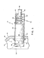
- the mechanical sensor 10 comprises a generally hollow housing member 36, having an open end 38, and a substantially closed radially opposed end 40.
- the open end 38 is engageable with an outside wall 18 of the housing 14 at a point radially opposed to the flexible clamp 26.
- the housing member 36 is a case, with an elongated cylindrical shape. It is also preferred that the material of the housing member 36 is metal.
- a first aperture 42 is formed through the substantially closed radially opposed end 40 of the housing member 36, and is in substantially axial alignment with a second aperture 44 formed through the wall of the housing 14, and a third aperture 46 formed through the flexible clamp 26.
- the first aperture 42 is substantially round.
- a first portion 50 of the slidable member 48 is disposed for reciprocal longitudinal movement within the generally hollow housing member 36.
- a second portion 52 of the slidable member 48 is connected to the first portion 50, and extends outwardly through the first aperture 42 in the radially opposed end 40 of the housing member 36. At least a portion of the first portion 50 extends through the second aperture 44 formed through the wall of the housing 14, and the third aperture 46 formed through the flexible clamp 26, for engagement with the first element 32 of the member 30 when the release shaft 28 is rotated to achieve and maintain full brake release.
- the first portion 50 and the second portion 52 of the slidable member 48 have a predetermined size, shape, and material. The preferred material is metal, and the preferred shape is substantially cylindrical.
- the diameter of the first portion 50 is substantially larger than the diameter of the second portion 52, and the diameter of the second portion 52 is smaller than the diameter of the first aperture 42.
- a means, generally designated 54, is provided for urging the slidable member 48 into a position wherein a predetermined length of the first portion 50 of the slidable member 48 is retracted through the second aperture 44 formed through the wall of the housing 14, and the third aperture 46 formed through the flexible clamp 26.
- the means 54 is a helical spring 56 of a predetermined length and load rating. The spring can be in compression or tension. Preferably, the spring 56 is in compression.
- a tension spring 58 suitably attached to the housing member 36 and the slidable member 48 can also be used to urge the slidable member 48 into position. It is also preferred that the spring is made of metal, and that the metal is steel.
- An attachment means, generally designated 60, is provided for securing the housing member 36 on the outside surface 18 of the wall 16 of the housing 14.
- the attachment means 60 can be at least one of welding, bolting, threading and screwing the housing member 36 into the second aperture 44 which has been threaded, and inserting a threaded portion 62 of the housing member 36 a predetermined distance through the second aperture 44, or fixing the housing member 36 with at least one of a threaded fastener 64 disposed on the threaded portion 62 of the housing member 36.
- Figure 4 illustrates the preferred means of securing the housing member 36 by inserting a threaded portion 62 of the housing member 36 a predetermined distance through the second aperture 44, and fixing the housing member 36 with two threaded fasteners 64 disposed on the threaded portion 62 of the housing member 36, opposing each other on the inside surface 17 of the wall 16 and the outside surface 18 of the wall 16 of the housing 14.
- a means 66 to prevent the slidable member 48 from traversing through the second aperture 44 of the housing 14 and the third aperture 46 of the flexible clamp 26 when the first element 32 is disengaged from the flexible clamp 26 is provided.
- the means 66 is at least one of a washer, pin, and flange disposed on the end of the second portion 52 of the slidable member 48.
- the release shaft 28 When full brake release is desired throughout train movement, the release shaft 28 is rotated.
- the first element 32 interposes with the flexible clamp 26, whereby the flexible clamp 26 secures the first element 32.
- the first portion 50 of the slidable member 48 protrudes through the open end 38 of the housing member 36, the second aperture 44 of the housing 14, and the third aperture 46 of the flexible clamp 26.
- the first lement 32 engages with the first portion 50 of the slidable member 48. This engagement displaces the slidable member 48 a predetermined distance through the housing member 36, causing the second portion 52 of the slidable member 48 to protrude through the first aperture 42 of the housing member 36.
- the protrusion of this second portion 52 is a visual indication that the hand brake is in the fully released position.
- the operating shaft 20 When brake application is desired, the operating shaft 20 is rotated in such a direction to move the projection 24 on the ratchet wheel 22 into engagement with the second element 34. This movement disengages the first element 32 from the flexible clamp 26, allowing the means 56 for urging the slidable member 48 to retract the second portion 52 of the slidable member 48 through the first aperture 42. The retraction of the second portion 52 of the slidable member 48 into the housing member 36 is a visual indication that the hand brake is in the brake application position.
Landscapes
- Engineering & Computer Science (AREA)
- Mechanical Engineering (AREA)
- Transportation (AREA)
- Braking Arrangements (AREA)
- Braking Elements And Transmission Devices (AREA)
- Valves And Accessory Devices For Braking Systems (AREA)
- Clamps And Clips (AREA)
Applications Claiming Priority (2)
| Application Number | Priority Date | Filing Date | Title |
|---|---|---|---|
| US09/874,449 US6474450B1 (en) | 2001-06-05 | 2001-06-05 | Mechanical sensor for a quick release hand brake |
| US874449 | 2001-06-05 |
Publications (3)
| Publication Number | Publication Date |
|---|---|
| EP1264751A2 true EP1264751A2 (fr) | 2002-12-11 |
| EP1264751A3 EP1264751A3 (fr) | 2003-03-05 |
| EP1264751B1 EP1264751B1 (fr) | 2004-12-29 |
Family
ID=25363799
Family Applications (1)
| Application Number | Title | Priority Date | Filing Date |
|---|---|---|---|
| EP02291209A Expired - Lifetime EP1264751B1 (fr) | 2001-06-05 | 2002-05-16 | Capteur mécanique pour un dispositif de relâche rapide d'un frein à main |
Country Status (10)
| Country | Link |
|---|---|
| US (1) | US6474450B1 (fr) |
| EP (1) | EP1264751B1 (fr) |
| CN (1) | CN1298576C (fr) |
| AU (1) | AU782042B2 (fr) |
| BR (1) | BR0201428A (fr) |
| CA (1) | CA2381848C (fr) |
| DE (1) | DE60202402D1 (fr) |
| MX (1) | MXPA02005555A (fr) |
| NZ (1) | NZ518507A (fr) |
| ZA (1) | ZA200203321B (fr) |
Cited By (3)
| Publication number | Priority date | Publication date | Assignee | Title |
|---|---|---|---|---|
| US20160167684A1 (en) * | 2014-12-16 | 2016-06-16 | Faiveley Transport Amiens | Rail vehicle braking system and braking method for a rail vehicle comprising such a system |
| CN105882679A (zh) * | 2014-12-31 | 2016-08-24 | 法维莱运输亚眠公司 | 用于铁路车辆的铁路制动系统和具有这种系统的铁路车辆的制动方法 |
| CN107499333A (zh) * | 2017-09-04 | 2017-12-22 | 中车青岛四方车辆研究所有限公司 | 停放制动缸手缓解装置 |
Families Citing this family (16)
| Publication number | Priority date | Publication date | Assignee | Title |
|---|---|---|---|---|
| US7093694B2 (en) * | 2003-03-21 | 2006-08-22 | Wabtec Holding Corp. | Release hold mechanism with gravity weighted indicator flag |
| US7021430B2 (en) * | 2003-03-25 | 2006-04-04 | Westinghouse Air Brake Technologies Corporation | Release hold mechanism for a hand brake having a quick release mechanism |
| US8033236B2 (en) * | 2005-09-16 | 2011-10-11 | Ellcon National, Inc. | Handbrake load indicator |
| US8839915B2 (en) * | 2005-10-18 | 2014-09-23 | Sharma & Associates, Inc. | Railway freight car hand brake sensor |
| US7757825B2 (en) * | 2007-05-30 | 2010-07-20 | Ellcon National, Inc. | Quick release hand brake |
| US8123004B2 (en) * | 2009-01-30 | 2012-02-28 | New York Air Brake Corporation | Rail handbrake with prolonged release |
| US9365223B2 (en) | 2010-08-23 | 2016-06-14 | Amsted Rail Company, Inc. | System and method for monitoring railcar performance |
| US9026281B2 (en) * | 2010-08-23 | 2015-05-05 | Amstead Rail Company, Inc. | Railcar handbrake monitor |
| US8616341B2 (en) | 2011-02-16 | 2013-12-31 | Wabtec Holding Corp | Device and method for sensing applied condition of a railroad handbrake |
| US8584551B2 (en) | 2011-02-16 | 2013-11-19 | Wabtec Holding Corp | Railroad handbrake chain tension condition sensing device and method |
| US10029713B2 (en) | 2015-01-09 | 2018-07-24 | New York Air Brake, LLC | Rail handbrake with prolonged release |
| WO2018141816A1 (fr) * | 2017-02-02 | 2018-08-09 | Ovinto Cvba | Procédé et système de surveillance d'un frein à main de wagon ferroviaire |
| MX2020007708A (es) | 2018-01-24 | 2020-12-09 | Amsted Rail Co Inc | Metodo, sistema y ensamble de deteccion de compuerta de descarga. |
| US12371077B2 (en) | 2018-01-24 | 2025-07-29 | Amsted Rail Company, Inc. | Sensing method, system and assembly for railway assets |
| WO2020014692A1 (fr) | 2018-07-12 | 2020-01-16 | Amsted Rail Company, Inc. | Systèmes de surveillance de frein pour wagons de chemin de fer |
| CN117108660A (zh) * | 2023-08-23 | 2023-11-24 | 中车眉山车辆有限公司 | 一种手制动机制动、缓解状态监测装置 |
Family Cites Families (10)
| Publication number | Priority date | Publication date | Assignee | Title |
|---|---|---|---|---|
| US3854417A (en) * | 1974-03-13 | 1974-12-17 | Mac R Co | Automatic visual hand brake system |
| US4368648A (en) * | 1980-06-23 | 1983-01-18 | American Standard Inc. | Hand brake for railroad car |
| US5738416A (en) * | 1994-07-22 | 1998-04-14 | Westinghouse Air Brake Company | Railway braking apparatus to effect a change in a handbrake |
| US5799545A (en) * | 1996-02-20 | 1998-09-01 | Westinghouse Air Brake Company | Ergonomic hand wheel for railway car hand brake |
| US6170619B1 (en) * | 1998-10-29 | 2001-01-09 | Honeywell Inc | Manual hand brake sensor for a railroad car |
| US6237722B1 (en) * | 1998-12-10 | 2001-05-29 | Honeywell International Inc | Railroad handbrake “off” sensor |
| US6397978B1 (en) * | 2000-07-31 | 2002-06-04 | John M. Jackson | Hand brake for a rail car |
| US6364428B1 (en) * | 2000-09-18 | 2002-04-02 | Westinghouse Air Brake Technologies Corporation | Apparatus for a quick release mechanism in a railcar hand brake |
| US6364069B1 (en) * | 2001-06-07 | 2002-04-02 | Westinghouse Air Brake Technologies Corporation | Electronic sensor for a quick release hand brake |
| US6394233B1 (en) * | 2001-07-13 | 2002-05-28 | Westinghouse Air Brake Technologies Corporation | Apparatus for operating a vertical wheel hand brake |
-
2001
- 2001-06-05 US US09/874,449 patent/US6474450B1/en not_active Expired - Lifetime
-
2002
- 2002-04-15 CA CA002381848A patent/CA2381848C/fr not_active Expired - Fee Related
- 2002-04-16 AU AU34350/02A patent/AU782042B2/en not_active Ceased
- 2002-04-19 NZ NZ518507A patent/NZ518507A/xx unknown
- 2002-04-25 BR BR0201428-9A patent/BR0201428A/pt not_active Application Discontinuation
- 2002-04-25 ZA ZA200203321A patent/ZA200203321B/xx unknown
- 2002-05-16 EP EP02291209A patent/EP1264751B1/fr not_active Expired - Lifetime
- 2002-05-16 DE DE60202402T patent/DE60202402D1/de not_active Expired - Lifetime
- 2002-05-23 CN CNB021203660A patent/CN1298576C/zh not_active Expired - Fee Related
- 2002-06-05 MX MXPA02005555A patent/MXPA02005555A/es active IP Right Grant
Non-Patent Citations (1)
| Title |
|---|
| None |
Cited By (7)
| Publication number | Priority date | Publication date | Assignee | Title |
|---|---|---|---|---|
| US20160167684A1 (en) * | 2014-12-16 | 2016-06-16 | Faiveley Transport Amiens | Rail vehicle braking system and braking method for a rail vehicle comprising such a system |
| US9956971B2 (en) * | 2014-12-16 | 2018-05-01 | Faiveley Transport Amiens | Rail vehicle braking system and braking method for a rail vehicle comprising such a system |
| US10501099B2 (en) | 2014-12-16 | 2019-12-10 | Faiveley Transport Amiens | Rail vehicle braking system and braking method for a rail vehicle comprising such a system |
| CN105882679A (zh) * | 2014-12-31 | 2016-08-24 | 法维莱运输亚眠公司 | 用于铁路车辆的铁路制动系统和具有这种系统的铁路车辆的制动方法 |
| CN105882679B (zh) * | 2014-12-31 | 2019-03-01 | 法维莱运输亚眠公司 | 用于铁路车辆的铁路制动系统和具有这种系统的铁路车辆的制动方法 |
| CN107499333A (zh) * | 2017-09-04 | 2017-12-22 | 中车青岛四方车辆研究所有限公司 | 停放制动缸手缓解装置 |
| CN107499333B (zh) * | 2017-09-04 | 2019-05-10 | 中车青岛四方车辆研究所有限公司 | 停放制动缸手缓解装置 |
Also Published As
| Publication number | Publication date |
|---|---|
| CN1390735A (zh) | 2003-01-15 |
| MXPA02005555A (es) | 2004-07-16 |
| NZ518507A (en) | 2003-01-31 |
| CA2381848C (fr) | 2005-07-26 |
| BR0201428A (pt) | 2003-02-11 |
| AU782042B2 (en) | 2005-06-30 |
| CA2381848A1 (fr) | 2002-12-05 |
| CN1298576C (zh) | 2007-02-07 |
| ZA200203321B (en) | 2002-11-04 |
| DE60202402D1 (de) | 2005-02-03 |
| US6474450B1 (en) | 2002-11-05 |
| EP1264751B1 (fr) | 2004-12-29 |
| AU3435002A (en) | 2002-12-12 |
| EP1264751A3 (fr) | 2003-03-05 |
Similar Documents
| Publication | Publication Date | Title |
|---|---|---|
| EP1264751B1 (fr) | Capteur mécanique pour un dispositif de relâche rapide d'un frein à main | |
| US4989537A (en) | Wear indicator for vehicle air brakes | |
| US4456233A (en) | Tensioning device for chains | |
| US4709654A (en) | Indicator for loose lug nuts | |
| US7461869B2 (en) | Air brake hose coupling with locking device | |
| EP1674354A2 (fr) | Rétracteur avec limiteur de force de niveaux multiples | |
| US5186586A (en) | Remote release device for load binders | |
| US5145299A (en) | Remote release device for load binders | |
| EP3812226B1 (fr) | Appareil frein de stationnement de véhicule | |
| EP3515758B1 (fr) | Tendeurs à levier et indicateurs de surcharge | |
| AU4030601A (en) | Apparatus for a quick release mechanism in a railcar hand brake | |
| US6694827B2 (en) | Fluid coupling with a torque indication device | |
| US7093694B2 (en) | Release hold mechanism with gravity weighted indicator flag | |
| US5320465A (en) | Blind pin fixing | |
| US5623751A (en) | Retractable binder for securing cargo loads | |
| US20110094313A1 (en) | Hand brake torque input coupler and indicator | |
| US8839915B2 (en) | Railway freight car hand brake sensor | |
| RU2134826C1 (ru) | Запорное устройство "закрутка-фал" | |
| WO1997020153A1 (fr) | Temoin de cylindre de frein destine a un frein de vehicule | |
| JPH08258702A (ja) | 鉄道車両用ブレーキシリンダ・ピストン行程視覚インジケータ装置 | |
| GB2127086A (en) | Automatic latch for use in scaffolding structures | |
| US5943940A (en) | Indication means in a brake cylinder for a vehicle brake | |
| US5127283A (en) | Handbrake mechanism for railway cars | |
| US4949602A (en) | Wrench | |
| EP4242472A1 (fr) | Écrou, ensemble de fixation et procédé de fixation d'une charge |
Legal Events
| Date | Code | Title | Description |
|---|---|---|---|
| PUAI | Public reference made under article 153(3) epc to a published international application that has entered the european phase |
Free format text: ORIGINAL CODE: 0009012 |
|
| AK | Designated contracting states |
Kind code of ref document: A2 Designated state(s): AT BE CH CY DE DK ES FI FR GB GR IE IT LI LU MC NL PT SE TR |
|
| AX | Request for extension of the european patent |
Free format text: AL;LT;LV;MK;RO;SI |
|
| PUAL | Search report despatched |
Free format text: ORIGINAL CODE: 0009013 |
|
| AK | Designated contracting states |
Designated state(s): AT BE CH CY DE DK ES FI FR GB GR IE IT LI LU MC NL PT SE TR Kind code of ref document: A3 Designated state(s): AT BE CH CY DE DK ES FI FR GB GR IE IT LI LU MC NL PT SE TR |
|
| AX | Request for extension of the european patent |
Extension state: AL LT LV MK RO SI |
|
| RIC1 | Information provided on ipc code assigned before grant |
Ipc: 7B 61H 13/34 B Ipc: 7B 61H 13/02 A Ipc: 7B 60T 17/22 B |
|
| 17P | Request for examination filed |
Effective date: 20030424 |
|
| AKX | Designation fees paid |
Designated state(s): DE FR GB IT |
|
| GRAP | Despatch of communication of intention to grant a patent |
Free format text: ORIGINAL CODE: EPIDOSNIGR1 |
|
| GRAS | Grant fee paid |
Free format text: ORIGINAL CODE: EPIDOSNIGR3 |
|
| GRAA | (expected) grant |
Free format text: ORIGINAL CODE: 0009210 |
|
| AK | Designated contracting states |
Kind code of ref document: B1 Designated state(s): DE FR GB IT |
|
| PG25 | Lapsed in a contracting state [announced via postgrant information from national office to epo] |
Ref country code: IT Free format text: LAPSE BECAUSE OF FAILURE TO SUBMIT A TRANSLATION OF THE DESCRIPTION OR TO PAY THE FEE WITHIN THE PRESCRIBED TIME-LIMIT;WARNING: LAPSES OF ITALIAN PATENTS WITH EFFECTIVE DATE BEFORE 2007 MAY HAVE OCCURRED AT ANY TIME BEFORE 2007. THE CORRECT EFFECTIVE DATE MAY BE DIFFERENT FROM THE ONE RECORDED. Effective date: 20041229 Ref country code: FR Free format text: LAPSE BECAUSE OF FAILURE TO SUBMIT A TRANSLATION OF THE DESCRIPTION OR TO PAY THE FEE WITHIN THE PRESCRIBED TIME-LIMIT Effective date: 20041229 |
|
| REG | Reference to a national code |
Ref country code: GB Ref legal event code: FG4D |
|
| REG | Reference to a national code |
Ref country code: IE Ref legal event code: FG4D |
|
| REF | Corresponds to: |
Ref document number: 60202402 Country of ref document: DE Date of ref document: 20050203 Kind code of ref document: P |
|
| PG25 | Lapsed in a contracting state [announced via postgrant information from national office to epo] |
Ref country code: DE Free format text: LAPSE BECAUSE OF FAILURE TO SUBMIT A TRANSLATION OF THE DESCRIPTION OR TO PAY THE FEE WITHIN THE PRESCRIBED TIME-LIMIT Effective date: 20050330 |
|
| PLBE | No opposition filed within time limit |
Free format text: ORIGINAL CODE: 0009261 |
|
| STAA | Information on the status of an ep patent application or granted ep patent |
Free format text: STATUS: NO OPPOSITION FILED WITHIN TIME LIMIT |
|
| 26N | No opposition filed |
Effective date: 20050930 |
|
| EN | Fr: translation not filed | ||
| PGFP | Annual fee paid to national office [announced via postgrant information from national office to epo] |
Ref country code: GB Payment date: 20070516 Year of fee payment: 6 |
|
| GBPC | Gb: european patent ceased through non-payment of renewal fee |
Effective date: 20080516 |
|
| PG25 | Lapsed in a contracting state [announced via postgrant information from national office to epo] |
Ref country code: GB Free format text: LAPSE BECAUSE OF NON-PAYMENT OF DUE FEES Effective date: 20080516 |