EP1264724A2 - Vehicular power unit arrangement structure and method - Google Patents
Vehicular power unit arrangement structure and method Download PDFInfo
- Publication number
- EP1264724A2 EP1264724A2 EP02253834A EP02253834A EP1264724A2 EP 1264724 A2 EP1264724 A2 EP 1264724A2 EP 02253834 A EP02253834 A EP 02253834A EP 02253834 A EP02253834 A EP 02253834A EP 1264724 A2 EP1264724 A2 EP 1264724A2
- Authority
- EP
- European Patent Office
- Prior art keywords
- power unit
- sub
- frame
- fore
- aft direction
- Prior art date
- Legal status (The legal status is an assumption and is not a legal conclusion. Google has not performed a legal analysis and makes no representation as to the accuracy of the status listed.)
- Granted
Links
- 238000000034 method Methods 0.000 title claims description 7
- 230000004044 response Effects 0.000 claims abstract description 7
- 239000000725 suspension Substances 0.000 claims description 5
- 229920001971 elastomer Polymers 0.000 claims description 3
- 239000012212 insulator Substances 0.000 claims description 3
- 239000005060 rubber Substances 0.000 claims description 3
- 238000005452 bending Methods 0.000 description 6
- 230000000694 effects Effects 0.000 description 3
- 230000008901 benefit Effects 0.000 description 2
- 238000009413 insulation Methods 0.000 description 2
- 239000000463 material Substances 0.000 description 2
- 238000003466 welding Methods 0.000 description 2
- 229910000838 Al alloy Inorganic materials 0.000 description 1
- 230000005540 biological transmission Effects 0.000 description 1
- 230000003247 decreasing effect Effects 0.000 description 1
- 238000001125 extrusion Methods 0.000 description 1
- 230000006872 improvement Effects 0.000 description 1
- 230000000116 mitigating effect Effects 0.000 description 1
- 238000012986 modification Methods 0.000 description 1
- 230000004048 modification Effects 0.000 description 1
- 238000005192 partition Methods 0.000 description 1
- 230000000644 propagated effect Effects 0.000 description 1
Images

Classifications
-
- B—PERFORMING OPERATIONS; TRANSPORTING
- B60—VEHICLES IN GENERAL
- B60K—ARRANGEMENT OR MOUNTING OF PROPULSION UNITS OR OF TRANSMISSIONS IN VEHICLES; ARRANGEMENT OR MOUNTING OF PLURAL DIVERSE PRIME-MOVERS IN VEHICLES; AUXILIARY DRIVES FOR VEHICLES; INSTRUMENTATION OR DASHBOARDS FOR VEHICLES; ARRANGEMENTS IN CONNECTION WITH COOLING, AIR INTAKE, GAS EXHAUST OR FUEL SUPPLY OF PROPULSION UNITS IN VEHICLES
- B60K5/00—Arrangement or mounting of internal-combustion or jet-propulsion units
- B60K5/12—Arrangement of engine supports
- B60K5/1208—Resilient supports
- B60K5/1216—Resilient supports characterised by the location of the supports relative to the motor or to each other
Definitions
- the present invention relates to a vehicular power unit arrangement structure and a method and, more particularly, to a vehicular power unit arrangement structure and its related method which enable a falling behavior of the power unit during a frontal collision of the vehicle to be stably controlled.
- Japanese Patent Application Laid-Open Publication No. H9-240291 discloses a vehicular power unit arrangement structure.
- Such a structure is comprised of right and left downwardly and curvedly contoured sub-frames that are disposed beneath a power-unit mounting room.
- a lower portion of the power unit is mounted to the right and left sub-frames, with an upper portion of the power unit being mounted to side-members which are disposed above the power-unit mounting room at right and left sides thereof in a way such that the power unit is ready to be released upon receipt of vertical load beyond a given value. That is, with such a structure, downward bending operation of the sub-frame during the frontal collision of the vehicle permits the power unit to fall down.
- the present invention has been completed with the above view and it is therefore an object of the present invention to provide a vehicular power unit arrangement structure and its related method which is enable to stably control a falling behavior of a power unit during a frontal collision of a vehicle while enabling the power unit to suitably get into an area beneath a vehicular compartment.
- a power unit arrangement structure for a vehicle which has a mounting room partitioned in front of a vehicular compartment for receiving a power unit, comprises: a side-member extending in a fore and aft direction of a mounting room and enabled to achieve buckling deformation in the fore and aft direction during a frontal collision; a sub-frame extending in the mounting room along the fore and aft direction at an area below the side-member; a mount member having respective an insulating function and permitting a power unit to be supported with the side-member, the mount member being capable of tearing in response to relative movement of the side-member and the power unit in the fore and aft direction during the frontal collision; a bent portion disposed at a substantially intermediate portion of the sub-frame in the fore and aft direction and having a downwardly bent configuration; and a connecting member connecting a lower portion of the power unit to the sub-frame in the vicinity of the bent portion.
- a power unit arrangement structure for a vehicle which has a mounting room partitioned in front of a vehicular compartment for receiving a power unit, comprises: a side-member extending in a fore and aft direction of a mounting room and enabled to achieve buckling deformation in the fore and aft direction during a frontal collision; a sub-frame extending in the mounting room along the fore and aft direction at an area below the side-member; a mount member having respective an insulating function and permitting a power unit to be supported with the side-member, the mount member being capable of tearing in response to relative movement of the side-member and the power unit in the fore and aft direction during the frontal collision; start point defining means, which is disposed at a substantially intermediate portion of the sub-frame along the fore and aft direction, for defining a start point to induce a downwardly convex deformation in the sub-frame during the frontal collision; and connecting means for connecting
- a method of controlling a falling behavior of a power unit of a vehicle which has a mounting room partitioned in front of a vehicular compartment for receiving the power unit, comprises: preparing a side-member extending in a fore and aft direction of a mounting room; preparing a sub-frame extending in the mounting room in the fore and aft direction at an area below the side-member, the sub-frame including a bent portion having a downwardly bent configuration formed at a substantially intermediate portion of the sub-frame along the fore and aft direction; preparing a mount member having insulating function and permitting a power unit to be supported with the side-member; preparing a connecting member connecting a lower portion of the power unit to a close proximity area of the bent portion of the sub-frame; causing the side-member to be subjected to buckling deformation in the fore and aft direction during a frontal collision; tearing the mount member in response to relative movement between the side-member
- a vehicular power unit arrangement structure and its related method of a preferred embodiment according to the present invention are described below in conjunction with the accompanied drawings. Also, in the drawings, frontward, rearward, rightward, leftward, upward and downward directions of the vehicle are correspondingly designated with reference symbols FR, RR, R, L, UPR and LWR, respectively.
- the power unit arrangement structure S for the vehicle V includes a pair of side-members 1, 1 which extends in a tore and aft direction at right and left sides of the vehicle V, with the side-members 1, 1 being placed at and facing right and left sides of a mounting room 3 for mounting a power unit 5.
- the right and left side-members 1, 1 have rear distal ends held in abutting engagement with a dash panel 2 and welded thereto by welding to partition the mounting room 3 and a vehicular compartment 4 from one another.
- the side-members 1, 1 extend rearward to go into an area beneath a toe-board sloping downward and to be joined thereto by welding.
- front distal ends of the side-members 1, 1 are suitably interconnected to one another by a cross member which is not shown.
- the side-members 1, 1 thus arranged form essential component parts for absorbing impact energy to be exerted to the vehicular compartment 4 during a frontal collision of the vehicle V. More particularly, the side-members 1, 1 are so constructed as to allow a buckling deformation in the fore and aft direction due to axial collapsing load acting on the vehicle V rearward during the frontal collision thereof. In order to have such a function, the side-members 1, 1 are realized in a closed cross sectional structure made of combined panel materials or in a closed cross sectional structure formed by extrusion of an aluminum alloy. If desired, each of the side-members 1, 1 may have a bellows type easy-to-collapse portion that induces the buckling deformation in the fore and aft direction.
- the power unit 5 has right and left sides which are supported with the side-members 1, 1, respectively, via mount members 6, 6 composed of insulator rubbers 6a, 6a respectively having noise and vibration insulation properties.
- mount members 6, 6 composed of insulator rubbers 6a, 6a respectively having noise and vibration insulation properties.
- a sub-frame 7 is disposed in the mounting room 3 and includes side-frames 7A, 7A extending longitudinally of the vehicle V at right and left sides thereof in an area below the side-members 1, 1, and a laterally extending front cross frame 7B connected to front ends of the side-frames 7A, 7A.
- the sub-frame 7 is structured in a so-called parallel cross configuration, and front distal ends of the right and left side-frames 7A, 7A are fixedly coupled to front seat segments 8, 8 extending downward from front distal ends of the side-members 1, 1, respectively, while rear distal ends of the side-frames 7A, 7A are also fixedly coupled to rear seat segments 9, 9 joined to and aligned with a lower surface of a toe board 2A.
- each of the bent portions 11, 11 corresponds to a top portion of a shallow V-shape configuration VS (designated by dotted crosshatch) in the side view, wherein the shallow V-shape configuration VS is formed into a downwardly facing convex configuration with the top position downward in a height approximately from several centimeters to ten and several centimeters, if it is assumend that each of the side-frames 7A, 7A has a length of approximately one meter.
- a lower portion of the power unit 5 is interconnected to connecting points 12A, 12A, disposed at just forward areas of the bent portions 11, 11 of the side-frames 7A, 7A, by means of rods 12, 12 serving as connecting members.
- Such connection is suitably performed using fixtures such as bolts and nuts.
- the power unit arrangement structure of the preferred embodiment includes low rigidity sections 13, 13 formed in regions between the bent portions 11, 11 of the side-frames 7A, 7A and the connecting points 12A, 12A between the rods 12, 12 and the side-frames 7A, 7A.
- These low rigidity sections 13, 13 are composed of parts having lower rigidities than those of the other areas of the side-frames 7A, 7A.
- the low rigidity sections 13, 13 are formed by decreasing their plate thicknesses than the other areas of the side-frames 7A, 7A, of course, the present invention is not limited thereto and the same function may be alternatively achieved with the use of parts, each of which is made of material having lower rigidity than that of the other areas of the side-frames 7A, 7A.
- suspension arms 14, 14, which serves as rigid bodies, are connected to and supported with rear areas in close proximity to the bent portions 11, 11, respectively.
- the power unit arrangement structure reliably exhibits a noise and vibration transmission control function to adequately preclude the noise and vibration caused by the power unit 5 from being undesirably propagated to the vehicle body because the power unit 5 is supported with the side-members 1, 1 via the mount members 6, 6 having the noise and vibration insulation functions.
- the left side-frame 7A having the V-shape configuration VS in the side view, of the sub-frame 7 is bent and deformed in an "L-shape" profile that faces downward at a start point provided by the bent portion 11 formed at the intermediate portion of the side-frame 7A in the longitudinal direction thereof.
- the mainly left side of the power unit 5 begins to drop and move downward such that the power unit 5 is pulled downward while, at the same time, the mainly left side of the power unit 5 is rotated in a rearward winding-down direction about a pivot formed by the deforming front seat segment 8 serving as the connecting member of the front side of the sub-frame 7.
- the mainly left side of the power unit 5 is caused to drop downward from a rear side of the same.
- the bending point of the left side of the sub-frame 7 is defined at the left bent portion 11 disposed at the intermediate portion in the longitudinal direction of the left side-frame, thereby permitting the power unit 5 to drop in an amount stabilized in a substantially maximum value.
- the mainly left side of the power unit 5 has a falling behavior to reliably allow the rear side of the same to drop and move into a stabilized position.
- the mainly left side of the power unit 5 is enabled to get into a region below the vehicular compartment 4 in a reliable manner to effectively limit the vehicular compartment 4 from being excessively deformed while effectively precluding a collapsing deformation of the left side-member 1 in the fore and aft direction from being inhibited with the power unit 5.
- the left side-member 1 has an increased collapsing stroke for thereby remarkably increasing an absorbing capability of impact energy.
- the left low rigidity section 13 is formed in the region between the bent portion 11 of the left side-frame 7A and the just rear area of the left connecting point 12A of the left rod 12, during the collision of the vehicle, the left rigidity section 13 induces a downward bending deformation at the start point provided by the bent portion 11 of the left side-frame 7A while, at the same time, the presence of the left suspension arm 14 connected to and supported with the just rear area of the left bent portion 11 allows the real area of the left bent portion 11 to have a highly rigid area to easily cause a stress concentration at the left bent portion 11 for thereby causing the power unit 5 to drop and move downward in a more reliable manner.
- the vibration-transfer mitigating capability is adequately enhanced for preventing vibration of the power unit from being transferred to the vehicle body.
- the mount member is torn resulting in the release of the power unit while, at the same time, the sub-frame formed with the V-shape configurations, when viewed in side plane, is deformed downward into the L-shape profile at the start point defined by the bent portion formed at the intermediate portion of the sub-frame in the longitudinal direction thereof.
- This causes the connecting member having the connecting member in the vicinity of the bent portion to pull the power unit downward to be dropped and moved.
- the power unit is exerted with rotational behavior in the rear warping direction about the pivot provided by the connecting portion of the front distal end of the side-frame, causing the power unit to drop from its rear side.
- the bending point of the sub-frame is established at the intermediate portion in the longitudinal direction of the sub-frame to allow the amount of dropping of the power unit to be stabilized at the substantially maximum value.
- the power unit is reliably caused to get into the area below the vehicular compartment to limit the excessive deformation of the vehicular compartment. When this takes place, moreover, the collapsible deformation of the side-member in its longitudinal direction is not interfered with the power unit, resulting in the increase in the collapsible stroke of the side-member for thereby providing an improved impact energy absorbing effect.
- the presence of the connecting point of the connecting member disposed at the immediately forward area of the bent portion of the sub-frame enables the falling behavior of the power unit to be initiated from the rear side in the reliable manner in a more stabilized fashion.
- the presence of the low rigidity section formed between the bent portion of the sub-frame and the connecting point of the connecting member induces the downward bending deformation of the sub-frame at the starting point provided by the bent portion thereof, enabling the falling operation of the power unit to be more reliably effectuated.
- the presence of the rigid suspension arm connected to and supported with the rear area of the bent portion of the sub-frame allows the rear area of the bent portion to have an increased rigid structure to cause the stress concentration to easily occur at the bent portion, enabling the falling operation of the power unit in a more reliable manner.
Landscapes
- Engineering & Computer Science (AREA)
- Chemical & Material Sciences (AREA)
- Combustion & Propulsion (AREA)
- Transportation (AREA)
- Mechanical Engineering (AREA)
- Body Structure For Vehicles (AREA)
- Arrangement Or Mounting Of Propulsion Units For Vehicles (AREA)
- Vibration Prevention Devices (AREA)
Abstract
Description
- The present invention relates to a vehicular power unit arrangement structure and a method and, more particularly, to a vehicular power unit arrangement structure and its related method which enable a falling behavior of the power unit during a frontal collision of the vehicle to be stably controlled.
- Japanese Patent Application Laid-Open Publication No. H9-240291 discloses a vehicular power unit arrangement structure. Such a structure is comprised of right and left downwardly and curvedly contoured sub-frames that are disposed beneath a power-unit mounting room. A lower portion of the power unit is mounted to the right and left sub-frames, with an upper portion of the power unit being mounted to side-members which are disposed above the power-unit mounting room at right and left sides thereof in a way such that the power unit is ready to be released upon receipt of vertical load beyond a given value. That is, with such a structure, downward bending operation of the sub-frame during the frontal collision of the vehicle permits the power unit to fall down.
- However, in such a structure, extensive studies undertaken by the present inventors have revealed that the presence of the curvedly contoured regions of the sub-frames tends to cause the sub-frame to bend in a wide range of an unstable bending region when the sub-frame is subjected to load exerted during the frontal collision of the vehicle. Thus, the need for further improvement in control of the amount of dropping of the power unit would be appeared.
- The present invention has been completed with the above view and it is therefore an object of the present invention to provide a vehicular power unit arrangement structure and its related method which is enable to stably control a falling behavior of a power unit during a frontal collision of a vehicle while enabling the power unit to suitably get into an area beneath a vehicular compartment.
- According to one aspect of the present invention, a power unit arrangement structure for a vehicle, which has a mounting room partitioned in front of a vehicular compartment for receiving a power unit, comprises: a side-member extending in a fore and aft direction of a mounting room and enabled to achieve buckling deformation in the fore and aft direction during a frontal collision; a sub-frame extending in the mounting room along the fore and aft direction at an area below the side-member; a mount member having respective an insulating function and permitting a power unit to be supported with the side-member, the mount member being capable of tearing in response to relative movement of the side-member and the power unit in the fore and aft direction during the frontal collision; a bent portion disposed at a substantially intermediate portion of the sub-frame in the fore and aft direction and having a downwardly bent configuration; and a connecting member connecting a lower portion of the power unit to the sub-frame in the vicinity of the bent portion. The sub-frame has a part having a substantially V-shaped configuration having the bent portion in a side view.
- In other words, in the present invention, a power unit arrangement structure for a vehicle, which has a mounting room partitioned in front of a vehicular compartment for receiving a power unit, comprises: a side-member extending in a fore and aft direction of a mounting room and enabled to achieve buckling deformation in the fore and aft direction during a frontal collision; a sub-frame extending in the mounting room along the fore and aft direction at an area below the side-member; a mount member having respective an insulating function and permitting a power unit to be supported with the side-member, the mount member being capable of tearing in response to relative movement of the side-member and the power unit in the fore and aft direction during the frontal collision; start point defining means, which is disposed at a substantially intermediate portion of the sub-frame along the fore and aft direction, for defining a start point to induce a downwardly convex deformation in the sub-frame during the frontal collision; and connecting means for connecting a lower portion of the power unit to the sub-frame in the vicinity of the bent portion. The sub-frame has a portion having a substantially V-shaped configuration in a side view.
- Besides, in the present invention, a method of controlling a falling behavior of a power unit of a vehicle, which has a mounting room partitioned in front of a vehicular compartment for receiving the power unit, comprises: preparing a side-member extending in a fore and aft direction of a mounting room; preparing a sub-frame extending in the mounting room in the fore and aft direction at an area below the side-member, the sub-frame including a bent portion having a downwardly bent configuration formed at a substantially intermediate portion of the sub-frame along the fore and aft direction; preparing a mount member having insulating function and permitting a power unit to be supported with the side-member; preparing a connecting member connecting a lower portion of the power unit to a close proximity area of the bent portion of the sub-frame; causing the side-member to be subjected to buckling deformation in the fore and aft direction during a frontal collision; tearing the mount member in response to relative movement between the side-member and the power unit in the fore and aft direction during the frontal direction; and causing the sub-frame to be bent in downwardly convex configuration at a starting point provided by the bent portion during the frontal collision.
- Other and further features, advantages, and benefits of the present invention will become more apparent from the following description taken in conjunction with the following drawings.
-
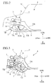
- Fig. 1 is a perspective view of a vehicular power unit arrangement structure, shown in a condition with a dash panel being omitted, of a preferred embodiment according to the present invention;
- Fig. 2 is a schematic side view of the vehicular power unit arrangement structure of the preferred embodiment; and
- Fig. 3 is a schematic side view of the vehicular power unit arrangement structure of the preferred embodiment in a frontal collision of a vehicle.
-
- A vehicular power unit arrangement structure and its related method of a preferred embodiment according to the present invention are described below in conjunction with the accompanied drawings. Also, in the drawings, frontward, rearward, rightward, leftward, upward and downward directions of the vehicle are correspondingly designated with reference symbols FR, RR, R, L, UPR and LWR, respectively.
- In Figs. 1 and 2, the power unit arrangement structure S for the vehicle V includes a pair of side-
members members mounting room 3 for mounting apower unit 5. The right and left side-members mounting room 3 and avehicular compartment 4 from one another. The side-members members - The side-
members vehicular compartment 4 during a frontal collision of the vehicle V. More particularly, the side-members members members - Further, the
power unit 5 has right and left sides which are supported with the side-members mount members insulator rubbers members power unit 5 are moved in the fore and aft direction with respect to one another in the frontal collision, themount members insulator rubbers power unit 5. Also, in the drawings, it is to be noted that thepower unit 5 is mounted in a so-called laterally arranged configuration. Moreover, it is to be noted that the present invention is not limited to such a direction in which the power unit is laterally arranged and may also be applied to a structure wherein the power unit is mounted in a so-called longitudinally arranged configuration. - Further, a
sub-frame 7 is disposed in themounting room 3 and includes side-frames members front cross frame 7B connected to front ends of the side-frames - More particularly, the
sub-frame 7 is structured in a so-called parallel cross configuration, and front distal ends of the right and left side-frames front seat segments members frames rear seat segments toe board 2A. - Further, the side-
frames sub-frame 7 have downwardly facingbent portions bent portions frames power unit 5 is interconnected to connectingpoints bent portions frames rods - As shown in a hatched area in Fig. 1, the power unit arrangement structure of the preferred embodiment includes
low rigidity sections bent portions frames connecting points rods frames low rigidity sections frames - Although the
low rigidity sections frames frames - In addition,
suspension arms bent portions - Also, it is to be noted that the right side,
bent portion 11,rod 12,low rigidity section 13 andsuspension arm 14 are omitted in the drawings for the sake of convenience. - Now, the operation of the vehicular power unit arrangement structure with such a structure described above is described more in detail.
- During normal state of the vehicle, firstly, the power unit arrangement structure reliably exhibits a noise and vibration transmission control function to adequately preclude the noise and vibration caused by the
power unit 5 from being undesirably propagated to the vehicle body because thepower unit 5 is supported with the side-members mount members - On the contrary, during the frontal collision of the vehicle, as shown in Fig. 3, assume that an impact load F is applied to a left, front face of the vehicle in a so-called offset manner. This causes a relative shift to occur in the fore and aft direction of the vehicle between the left side-
member 1 and thepower unit 5 and thus to tear theleft mount member 6, resulting in a release of thepower unit 5. - Simultaneously, the left side-
frame 7A, having the V-shape configuration VS in the side view, of thesub-frame 7 is bent and deformed in an "L-shape" profile that faces downward at a start point provided by thebent portion 11 formed at the intermediate portion of the side-frame 7A in the longitudinal direction thereof. Then, due to theleft rod 12 connected to the connectingpoint 12A just ahead of thebent portion 11, the mainly left side of thepower unit 5 begins to drop and move downward such that thepower unit 5 is pulled downward while, at the same time, the mainly left side of thepower unit 5 is rotated in a rearward winding-down direction about a pivot formed by the deformingfront seat segment 8 serving as the connecting member of the front side of thesub-frame 7. As a result, the mainly left side of thepower unit 5 is caused to drop downward from a rear side of the same. - With such operation, the bending point of the left side of the
sub-frame 7 is defined at theleft bent portion 11 disposed at the intermediate portion in the longitudinal direction of the left side-frame, thereby permitting thepower unit 5 to drop in an amount stabilized in a substantially maximum value. Simultaneously, the mainly left side of thepower unit 5 has a falling behavior to reliably allow the rear side of the same to drop and move into a stabilized position. As a result, the mainly left side of thepower unit 5 is enabled to get into a region below thevehicular compartment 4 in a reliable manner to effectively limit thevehicular compartment 4 from being excessively deformed while effectively precluding a collapsing deformation of the left side-member 1 in the fore and aft direction from being inhibited with thepower unit 5. Thus, the left side-member 1 has an increased collapsing stroke for thereby remarkably increasing an absorbing capability of impact energy. - In the preferred embodiment, further, since the left
low rigidity section 13 is formed in the region between thebent portion 11 of the left side-frame 7A and the just rear area of the left connectingpoint 12A of theleft rod 12, during the collision of the vehicle, theleft rigidity section 13 induces a downward bending deformation at the start point provided by thebent portion 11 of the left side-frame 7A while, at the same time, the presence of theleft suspension arm 14 connected to and supported with the just rear area of theleft bent portion 11 allows the real area of theleft bent portion 11 to have a highly rigid area to easily cause a stress concentration at theleft bent portion 11 for thereby causing thepower unit 5 to drop and move downward in a more reliable manner. - While the foregoing description of the operation of the preferred embodiment has been made in conjunction with an example applied to the so-called left offset type frontal collision of the vehicle, it is to be noted that the present invention may provide the same effect even in a so-called right offset type frontal collision or in an entire frontal collision involving collisions of the both types.
- As set forth above, according to a structure of the preferred embodiment, during the normal state, since the power unit is supported with the side-members via the mount members having respective anti-vibrating functions, the vibration-transfer mitigating capability is adequately enhanced for preventing vibration of the power unit from being transferred to the vehicle body. During the frontal collision of the vehicle, further, due to the relative movement between the side-members and the power unit in the fore and aft direction thereof, the mount member is torn resulting in the release of the power unit while, at the same time, the sub-frame formed with the V-shape configurations, when viewed in side plane, is deformed downward into the L-shape profile at the start point defined by the bent portion formed at the intermediate portion of the sub-frame in the longitudinal direction thereof. This causes the connecting member having the connecting member in the vicinity of the bent portion to pull the power unit downward to be dropped and moved. In addition to such effect, the power unit is exerted with rotational behavior in the rear warping direction about the pivot provided by the connecting portion of the front distal end of the side-frame, causing the power unit to drop from its rear side.
- Consequently, the bending point of the sub-frame is established at the intermediate portion in the longitudinal direction of the sub-frame to allow the amount of dropping of the power unit to be stabilized at the substantially maximum value. Also, the power unit is reliably caused to get into the area below the vehicular compartment to limit the excessive deformation of the vehicular compartment. When this takes place, moreover, the collapsible deformation of the side-member in its longitudinal direction is not interfered with the power unit, resulting in the increase in the collapsible stroke of the side-member for thereby providing an improved impact energy absorbing effect.
- Furthermore, the presence of the connecting point of the connecting member disposed at the immediately forward area of the bent portion of the sub-frame enables the falling behavior of the power unit to be initiated from the rear side in the reliable manner in a more stabilized fashion.
- Also, the presence of the low rigidity section formed between the bent portion of the sub-frame and the connecting point of the connecting member induces the downward bending deformation of the sub-frame at the starting point provided by the bent portion thereof, enabling the falling operation of the power unit to be more reliably effectuated.
- Finally, the presence of the rigid suspension arm connected to and supported with the rear area of the bent portion of the sub-frame allows the rear area of the bent portion to have an increased rigid structure to cause the stress concentration to easily occur at the bent portion, enabling the falling operation of the power unit in a more reliable manner.
- The entire content of a Patent Application No. TOKUGAN 2001-168115 with a filing date of June 4, 2001 in Japan is hereby incorporated by reference.
- Although the invention has been described above by reference to a certain embodiment of the invention, the invention is not limited to the embodiment described above. Modifications and variations of the embodiment described above will occur to those skilled in the art, in light of the teachings. The scope of the invention is defined with reference to the following claims.
Claims (8)
- A power unit arrangement structure (S) for a vehicle (V), which has a mounting room (3) partitioned in front of a vehicular compartment (4) for receiving a power unit (5), comprising:wherein the sub-frame has a part having a substantially V-shaped configuration (VS) having the bent portion in a side view.a side-member (1) extending in a fore and aft direction of a mounting room and enabled to achieve buckling deformation in the fore and aft direction during a frontal collision;a sub-frame (7) extending in the mounting room along the fore and aft direction at an area below the side-member;a mount member (6) having respective an insulating function and permitting a power unit to be supported with the side-member, the mount member being capable of tearing in response to relative movement of the side-member and the power unit in the fore and aft direction during the frontal collision;a bent portion (11) disposed at a substantially intermediate portion of the sub-frame in the fore and aft direction and having a downwardly bent configuration; anda connecting member (12) connecting a lower portion of the power unit to the sub-frame in the vicinity of the bent portion,
- A power unit arrangement structure according to claim 1, wherein the connecting member (12) has a connecting point (12A) disposed at a just front area of the bent portion (11) of the sub-frame (7) for connecting the power unit (5) to a portion in the vicinity of the bent portion of the sub-frame.
- A power unit arrangement structure according to claim 1 or 2, wherein the sub-frame (7) has a low rigidity section (13) formed between the bent portion (11) of the sub-frame (7) and a connecting point (12A) of the connecting member (12) by which the power unit (5) is connected to a portion in the vicinity of the bent portion of the sub-frame.
- A power unit arrangement structure according to any one of claims 1 to 3, further comprising a suspension arm (14) connected to and supported with a just rear area of the bent portion (11) of the sub-frame (7).
- A power unit arrangement structure according to any one of claims 1 to 4, wherein the side-member (1), a part of the sub-frame (7), the mount member (6) and the connecting member (12) are located at right and left sides, respectively.
- A power unit arrangement structure according to any one of claims 1 to 5, wherein the sub-frame (7) is formed in a cross configuration and has front a distal end connected to and fixed to a seat segment (8) extending downward from a front distal end of the side-member (1), with a rear distal end of the sub-frame being coupled to and fixed to a seat segment (9) joined to a lower surface of a toe board (2A) disposed in front of the vehicular compartment (4).
- A power unit arrangement structure according to any one of claims 1 to 6, wherein the insulating function of the mount member (6) is exhibited by an insulator rubber (6a) which is enabled to be torn in response to the relative movement between the side-member (1) and the power unit (5) in the fore and aft direction during the frontal collision.
- A method of controlling a falling behavior of a power unit (5) of a vehicle (V), which has a mounting room (3) partitioned in front of a vehicular compartment (4) for receiving the power unit, comprising:preparing a side-member (1) extending in a fore and aft direction of a mounting room;preparing a sub-frame (7) extending in the mounting room in the fore and aft direction at an area below the side-member, the sub-frame including a bent portion (11) having a downwardly bent configuration formed at a substantially intermediate portion of the sub-frame along the fore and aft direction;preparing a mount member (6) having insulating function and permitting a power unit to be supported with the side-member;preparing a connecting member (12) connecting a lower portion of the power unit to a close proximity area of the bent portion of the sub-frame;causing the side-member to be subjected to buckling deformation in the fore and aft direction during a frontal collision;tearing the mount member in response to relative movement between the side-member and the power unit in the fore and aft direction during the frontal direction; andcausing the sub-frame to be bent in downwardly convex configuration at a starting point provided by the bent portion during the frontal collision.
Applications Claiming Priority (2)
| Application Number | Priority Date | Filing Date | Title |
|---|---|---|---|
| JP2001168115 | 2001-06-04 | ||
| JP2001168115A JP3575439B2 (en) | 2001-06-04 | 2001-06-04 | Automotive power unit layout |
Publications (3)
| Publication Number | Publication Date |
|---|---|
| EP1264724A2 true EP1264724A2 (en) | 2002-12-11 |
| EP1264724A3 EP1264724A3 (en) | 2004-12-15 |
| EP1264724B1 EP1264724B1 (en) | 2008-07-09 |
Family
ID=19010391
Family Applications (1)
| Application Number | Title | Priority Date | Filing Date |
|---|---|---|---|
| EP02253834A Expired - Lifetime EP1264724B1 (en) | 2001-06-04 | 2002-05-31 | Vehicular power unit arrangement structure and method |
Country Status (4)
| Country | Link |
|---|---|
| US (1) | US6722696B2 (en) |
| EP (1) | EP1264724B1 (en) |
| JP (1) | JP3575439B2 (en) |
| DE (1) | DE60227454D1 (en) |
Families Citing this family (31)
| Publication number | Priority date | Publication date | Assignee | Title |
|---|---|---|---|---|
| JP4576780B2 (en) * | 2001-09-21 | 2010-11-10 | マツダ株式会社 | Body frame structure and method for manufacturing body frame |
| JP3900048B2 (en) * | 2001-11-19 | 2007-04-04 | 日産自動車株式会社 | Body front structure |
| JP4023208B2 (en) * | 2002-05-10 | 2007-12-19 | 日産自動車株式会社 | Powertrain support device |
| GB0214773D0 (en) * | 2002-06-26 | 2002-08-07 | Ford Global Tech Inc | Vehicle chassis |
| JP3842204B2 (en) * | 2002-11-11 | 2006-11-08 | 本田技研工業株式会社 | Front body structure |
| JP4144350B2 (en) * | 2002-12-26 | 2008-09-03 | トヨタ自動車株式会社 | Vehicle front body structure |
| JP4346313B2 (en) * | 2003-01-08 | 2009-10-21 | 富士重工業株式会社 | Auto body front structure |
| EP1510444B1 (en) * | 2003-08-25 | 2006-01-11 | Ford Global Technologies, LLC, A subsidary of Ford Motor Company | Motor vehicle subframe arrangement with improved crash safety |
| DE602004024325D1 (en) * | 2003-09-29 | 2010-01-07 | Nissan Motor | DRIVE MOTOR MOUNTING CONSTRUCTION AND FASTENING METHOD |
| DE102004018977B4 (en) * | 2004-04-20 | 2014-08-28 | Valmet Automotive Oy | motor vehicle |
| JP4630022B2 (en) * | 2004-08-30 | 2011-02-09 | 東海ゴム工業株式会社 | Vehicle safety device and pull-down rod used therefor |
| JP4276185B2 (en) * | 2005-01-26 | 2009-06-10 | 本田技研工業株式会社 | Body front structure |
| US7699346B2 (en) * | 2005-03-23 | 2010-04-20 | Chrysler Group Llc | Force redistributing system for a vehicle in the event of a rear impact |
| WO2007037113A1 (en) * | 2005-09-27 | 2007-04-05 | Autoliv Development Ab | Impact reducing structure of vehicle |
| EP1977956B1 (en) * | 2007-04-03 | 2012-08-29 | Nissan Motor Co., Ltd. | Installation structure and method of vehicular suspension |
| JP4529997B2 (en) * | 2007-04-27 | 2010-08-25 | トヨタ自動車株式会社 | Body front structure |
| US8550543B2 (en) * | 2009-10-26 | 2013-10-08 | Toyota Jidosha Kabushiki Kaisha | Vehicle body structure |
| DE102010048102A1 (en) * | 2010-10-09 | 2012-04-12 | Audi Ag | Vehicle with a crash energy absorbable traction battery |
| JP5811769B2 (en) * | 2011-10-27 | 2015-11-11 | トヨタ自動車株式会社 | Vehicle front structure |
| US8708401B2 (en) * | 2012-03-22 | 2014-04-29 | Ford Global Technologies, Llc | Crash brace for energy management |
| ITTO20130474A1 (en) * | 2013-06-07 | 2014-12-08 | Fiat Group Automobiles Spa | MOTOR VEHICLE EQUIPPED WITH A RELEASE SYSTEM TO DETACH A CROSS IN THE ENGINE COMPARTMENT IN CASE OF FRONTAL IMPACT |
| US10370035B2 (en) * | 2016-12-08 | 2019-08-06 | Inevit Llc | Motor guidance component configured to direct movement of a dislodged electric motor of an electric vehicle in response to crash forces |
| JP6819439B2 (en) * | 2017-04-21 | 2021-01-27 | トヨタ自動車株式会社 | Fuel cell vehicle |
| GB2570116B (en) * | 2018-01-10 | 2021-01-13 | Ford Global Tech Llc | Transmission roll initiator |
| DE102018118500A1 (en) * | 2018-07-31 | 2020-02-06 | Dr. Ing. H.C. F. Porsche Aktiengesellschaft | Electric vehicle component |
| JP7267810B2 (en) * | 2019-03-29 | 2023-05-02 | 株式会社エフテック | vehicle subframe |
| MX2022010848A (en) * | 2020-03-04 | 2022-09-27 | Nissan Motor | VEHICLE ASSEMBLY STRUCTURE FOR ELECTRICAL UNIT. |
| JP2022073718A (en) * | 2020-11-02 | 2022-05-17 | 株式会社エフテック | Sub frame for vehicle |
| JP2024007745A (en) * | 2022-07-06 | 2024-01-19 | 株式会社Subaru | fuel cell car |
| JP2024101759A (en) * | 2023-01-18 | 2024-07-30 | 株式会社Subaru | vehicle |
| JP2025152681A (en) * | 2024-03-28 | 2025-10-10 | マツダ株式会社 | Vehicle front structure |
Citations (2)
| Publication number | Priority date | Publication date | Assignee | Title |
|---|---|---|---|---|
| JPH09240291A (en) | 1995-12-27 | 1997-09-16 | Toyota Motor Corp | Powertrain support equipment |
| JP2001168115A (en) | 1999-10-29 | 2001-06-22 | Nordson Corp | Method and apparatus for underfilling a semiconductor device |
Family Cites Families (7)
| Publication number | Priority date | Publication date | Assignee | Title |
|---|---|---|---|---|
| US3578782A (en) * | 1969-10-29 | 1971-05-18 | Honda Motor Co Ltd | Apparatus for the retraction of a steering wheel of a vehicle in the event of a front end collision thereof |
| FR2120386A5 (en) * | 1970-12-31 | 1972-08-18 | Peugeot & Renault | |
| US5372216A (en) * | 1990-10-08 | 1994-12-13 | Mazda Motor Corporation | Power plant supporting structure of automotive vehicle |
| US5267630A (en) * | 1991-04-23 | 1993-12-07 | Mazda Motor Corporation | Front body structure of automotive vehicle |
| JP2650167B2 (en) * | 1991-06-24 | 1997-09-03 | 日産自動車株式会社 | Automotive power plant support equipment |
| DE4326396C2 (en) * | 1993-08-06 | 2001-07-26 | Daimler Chrysler Ag | Motor vehicle with a drive motor inclined at an acute angle to the horizontal |
| JP3188946B2 (en) * | 1994-12-02 | 2001-07-16 | ダイハツ工業株式会社 | Car steering gear support structure |
-
2001
- 2001-06-04 JP JP2001168115A patent/JP3575439B2/en not_active Expired - Fee Related
-
2002
- 2002-05-31 EP EP02253834A patent/EP1264724B1/en not_active Expired - Lifetime
- 2002-05-31 DE DE60227454T patent/DE60227454D1/en not_active Expired - Lifetime
- 2002-06-04 US US10/160,271 patent/US6722696B2/en not_active Expired - Fee Related
Patent Citations (2)
| Publication number | Priority date | Publication date | Assignee | Title |
|---|---|---|---|---|
| JPH09240291A (en) | 1995-12-27 | 1997-09-16 | Toyota Motor Corp | Powertrain support equipment |
| JP2001168115A (en) | 1999-10-29 | 2001-06-22 | Nordson Corp | Method and apparatus for underfilling a semiconductor device |
Also Published As
| Publication number | Publication date |
|---|---|
| EP1264724B1 (en) | 2008-07-09 |
| US20030011184A1 (en) | 2003-01-16 |
| US6722696B2 (en) | 2004-04-20 |
| JP3575439B2 (en) | 2004-10-13 |
| EP1264724A3 (en) | 2004-12-15 |
| JP2002362167A (en) | 2002-12-18 |
| DE60227454D1 (en) | 2008-08-21 |
Similar Documents
| Publication | Publication Date | Title |
|---|---|---|
| US6722696B2 (en) | Vehicular power unit arrangement structure and method | |
| EP1225072B1 (en) | Power unit layout structure | |
| US8672393B2 (en) | Front vehicle body structure | |
| US6811211B2 (en) | Vehicle body front structure | |
| JP3644395B2 (en) | Automotive power unit layout | |
| US10988179B2 (en) | Lower structure of vehicle | |
| JP3606252B2 (en) | Body front structure | |
| CN101595026A (en) | Vehicle front side member | |
| JP5209353B2 (en) | Body front structure | |
| JP7177821B2 (en) | Body front structure | |
| US11104383B2 (en) | Vehicle front portion structure | |
| JP2025014328A (en) | Front body structure | |
| JP5896827B2 (en) | Auto body frame structure | |
| JP7177819B2 (en) | Body front structure | |
| JP2003160061A (en) | Front body structure of passenger car | |
| JP5760979B2 (en) | Vehicle front structure | |
| JP3182973B2 (en) | Front body structure | |
| US12134422B2 (en) | Vehicle front body structure | |
| JP2002120752A (en) | Car front body structure | |
| JP2020011533A (en) | Vehicle undercarriage | |
| JP2002192958A (en) | Car power unit support structure | |
| JP7256996B2 (en) | vehicle front structure | |
| JPH05105118A (en) | Supporting structure for car suspension spring | |
| JP7144527B2 (en) | Front subframe structure | |
| EP2428432A1 (en) | Front side vehicle body structure |
Legal Events
| Date | Code | Title | Description |
|---|---|---|---|
| PUAI | Public reference made under article 153(3) epc to a published international application that has entered the european phase |
Free format text: ORIGINAL CODE: 0009012 |
|
| 17P | Request for examination filed |
Effective date: 20020613 |
|
| AK | Designated contracting states |
Kind code of ref document: A2 Designated state(s): AT BE CH CY DE DK ES FI FR GB GR IE IT LI LU MC NL PT SE TR |
|
| AX | Request for extension of the european patent |
Free format text: AL;LT;LV;MK;RO;SI |
|
| PUAL | Search report despatched |
Free format text: ORIGINAL CODE: 0009013 |
|
| AK | Designated contracting states |
Kind code of ref document: A3 Designated state(s): AT BE CH CY DE DK ES FI FR GB GR IE IT LI LU MC NL PT SE TR |
|
| AX | Request for extension of the european patent |
Extension state: AL LT LV MK RO SI |
|
| RIC1 | Information provided on ipc code assigned before grant |
Ipc: 7B 62D 21/15 B Ipc: 7B 60K 5/12 A |
|
| 17Q | First examination report despatched |
Effective date: 20050705 |
|
| AKX | Designation fees paid |
Designated state(s): DE FR GB |
|
| 17Q | First examination report despatched |
Effective date: 20050705 |
|
| GRAP | Despatch of communication of intention to grant a patent |
Free format text: ORIGINAL CODE: EPIDOSNIGR1 |
|
| GRAS | Grant fee paid |
Free format text: ORIGINAL CODE: EPIDOSNIGR3 |
|
| GRAA | (expected) grant |
Free format text: ORIGINAL CODE: 0009210 |
|
| AK | Designated contracting states |
Kind code of ref document: B1 Designated state(s): DE FR GB |
|
| REG | Reference to a national code |
Ref country code: GB Ref legal event code: FG4D |
|
| REF | Corresponds to: |
Ref document number: 60227454 Country of ref document: DE Date of ref document: 20080821 Kind code of ref document: P |
|
| PLBE | No opposition filed within time limit |
Free format text: ORIGINAL CODE: 0009261 |
|
| STAA | Information on the status of an ep patent application or granted ep patent |
Free format text: STATUS: NO OPPOSITION FILED WITHIN TIME LIMIT |
|
| 26N | No opposition filed |
Effective date: 20090414 |
|
| PGFP | Annual fee paid to national office [announced via postgrant information from national office to epo] |
Ref country code: FR Payment date: 20110523 Year of fee payment: 10 |
|
| PGFP | Annual fee paid to national office [announced via postgrant information from national office to epo] |
Ref country code: GB Payment date: 20110525 Year of fee payment: 10 |
|
| PGFP | Annual fee paid to national office [announced via postgrant information from national office to epo] |
Ref country code: DE Payment date: 20110525 Year of fee payment: 10 |
|
| GBPC | Gb: european patent ceased through non-payment of renewal fee |
Effective date: 20120531 |
|
| REG | Reference to a national code |
Ref country code: FR Ref legal event code: ST Effective date: 20130131 |
|
| REG | Reference to a national code |
Ref country code: DE Ref legal event code: R119 Ref document number: 60227454 Country of ref document: DE Effective date: 20121201 |
|
| PG25 | Lapsed in a contracting state [announced via postgrant information from national office to epo] |
Ref country code: FR Free format text: LAPSE BECAUSE OF NON-PAYMENT OF DUE FEES Effective date: 20120531 Ref country code: GB Free format text: LAPSE BECAUSE OF NON-PAYMENT OF DUE FEES Effective date: 20120531 |
|
| PG25 | Lapsed in a contracting state [announced via postgrant information from national office to epo] |
Ref country code: DE Free format text: LAPSE BECAUSE OF NON-PAYMENT OF DUE FEES Effective date: 20121201 |