EP1264663A2 - Spannvorrichtung - Google Patents
Spannvorrichtung Download PDFInfo
- Publication number
- EP1264663A2 EP1264663A2 EP02253908A EP02253908A EP1264663A2 EP 1264663 A2 EP1264663 A2 EP 1264663A2 EP 02253908 A EP02253908 A EP 02253908A EP 02253908 A EP02253908 A EP 02253908A EP 1264663 A2 EP1264663 A2 EP 1264663A2
- Authority
- EP
- European Patent Office
- Prior art keywords
- cam
- workpiece clamp
- jaw
- clamp
- actuated workpiece
- Prior art date
- Legal status (The legal status is an assumption and is not a legal conclusion. Google has not performed a legal analysis and makes no representation as to the accuracy of the status listed.)
- Withdrawn
Links
Images


Classifications
-
- B—PERFORMING OPERATIONS; TRANSPORTING
- B25—HAND TOOLS; PORTABLE POWER-DRIVEN TOOLS; MANIPULATORS
- B25B—TOOLS OR BENCH DEVICES NOT OTHERWISE PROVIDED FOR, FOR FASTENING, CONNECTING, DISENGAGING OR HOLDING
- B25B5/00—Clamps
- B25B5/06—Arrangements for positively actuating jaws
- B25B5/08—Arrangements for positively actuating jaws using cams
- B25B5/087—Arrangements for positively actuating jaws using cams actuated by a hydraulic or pneumatic piston
Definitions
- the present application relates to fluid pressure actuated clamps of the type employed in automated workpiece handling devices which clampingly grip, and illustratively transfer a workpiece from one station to another. More particularly, the present invention relates to fluid pressure actuated enclosed clamps for gripping a workpiece.
- Fluid pressure actuated grippers and clamps are widely employed and typically take the form of a pneumatic or hydraulic differential motor or actuator whose cylinder is fixedly mounted to a transfer device.
- a swing arm is coupled to the actuator and translates the movement, which is typically linear, into rotational movement.
- the arm is then rotatable between open and closed positions relative to another arm or clamping structure.
- the clamp jaws close on a workpiece near the edge of the same and will then advance to a work station or some other operation. The clamp will then open to release the workpiece.
- the clamp comprises an actuator, a body, a linkage, a cam member, a cam pin, and at least one jaw member.
- the body comprises a slot longitudinally-extending therein.
- the linkage is disposed in the slot, and is coupled to the actuator for longitudinal movement within the slot.
- the cam member comprises a cam track disposed therein and a pivot mounting extending therefrom.
- the cam pin is coupled to the linkage, and is disposed in the cam track.
- At least one jaw member is attached to the pivot mounting. The longitudinal movement of the linkage causes movement of the cam pin along the cam track to cause pivoting of the cam member about the pivot mounting which pivots the jaw member relative to the body.
- actuated workpiece clamp may further comprise at least one jaw member being a plurality of jaw members with at least one being fixedly attached to the body; a stop that couples to the body and selectively engages the cam member to limit pivoting of same to a defined stroke; at least one jaw member being a pivot jaw member being pivotably attached to the body independent of the cam member; a housing that attaches to the body and encloses the cam member; the cam track being arcuate; the linkage being attached to a piston rod extending from the actuator; the linkage being movable longitudinally in a first plane, and the cam member being pivotable in a second plane which is spaced apart from and substantially parallel to the first plane; one jaw member which is fixedly attached to the body is attached to the housing; and the stop being variable to selectively limit the defined stroke.
- actuated workpiece clamp comprises a coupling, a member, a movable body, a housing, and a jaw.
- the member is attached to the coupling and extends therefrom.
- the movable body has a slot disposed therethrough.
- the pivot coupling is attached to the movable body.
- the member engages the slot to pivot the movable body about the pivot coupling.
- the housing encloses the coupling, the member, and the movable body, and has an opening disposed therein to allow the pivot coupling to extend therethrough.
- the jaw is attached to the pivot coupling and is located exteriorly of the housing, and is movable relative to the housing.
- actuated workpiece clamp may further comprise a second jaw that is fixedly attached to the movable body; a stop positioned within the housing that selectively engages the movable body to limit pivoting of same to a defined stroke; a pivot jaw pivotably attached to the housing independent of the movable body; and the coupling and member being movable longitudinally in a first plane; the movable body being pivotable in a second plane which is spaced apart from and substantially parallel to the first plane; and the slot being defined by an arcuate path.
- actuated workpiece clamp comprises an actuator, a linkage, and a cam member.
- the actuator produces a longitudinal movement.
- the linkage extends transversely to and moves coincidentally with the longitudinal movement of the actuator.
- the cam member has a cam pathway disposed therein The linkage is disposed in the cam pathway, and the longitudinal movement of the actuator is translated into rotational movement in the cam member.
- actuated workpiece clamp comprises a clamp body, an actuator, a jaw member and a jaw tip.
- the actuator assembly defines a longitudinal axis along which at least a portion of the assembly moves.
- the jaw member is coupled to the body.
- the jaw tip is pivotable relative to the clamp body and is pivotable transversely relative to the longitudinal axis.
- FIG. 1 A forward perspective view of a fluid actuated clamp 2 is shown in Fig. 1.
- Clamp 2 is illustratively actuated by linear fluid actuator 4.
- Fluid ports 6, 8 are disposed in body 10 to provide power to actuator 4.
- the actuator is a pneumatic actuator with port 6, 8 being air extension and retraction ports. It is appreciated, however, that the actuator may be hydraulic, electrical or other power source.
- the power source and the actuator illustratively provide linear power that clamp 2 translates into rotational power to provide rotary motion to clamp arm assembly 12.
- a mounting bracket 14 is shown in Fig. 1 for mounting clamp 2 to an articulated support or transfer device.
- Mounting bracket 14 illustratively comprises a plurality of plate portions 16, 18 which are secured together by screws, bolts, or other like fasteners which extend into threaded bores of each plate portion.
- Body 10 comprises a narrowed portion or collar 20. This collar 20 is received in an opening (not shown) in mounting bracket 14. The clamp can, thus, freely rotate with respect to the mounting plate 27.
- Mounting bracket 14 further comprises an opening 22 which receives a spherical collar 24 that can be clamped therein in a selectively fixed orientation and used to mount the gripper device to an articulated structure.
- Housing portions 28, 30, 32 illustratively are part of body 10 located adjacent collar 20 distal from the actuator 4.
- translational mechanisms i.e., the mechanisms that translate linear motion to rotational motion
- Arm assembly 12 is located exteriorly of housing 34 and is attached to a hub 40, which extends through housing portion 32 via fasteners 42.
- a second clamp arm assembly 26 extends from housing 34, and comprises a tip 36 attached thereto that aligns with tip 38 of arm assembly 12 when clamp arm assemblies 12, 26 are in the closed or clamped position. These tips provide the gripping surfaces for the clamps when arm assembly 12 is in the closed or clamped position.
- FIG. 2 A partially exploded view of the second fluid actuated clamp arm assembly 26 is shown in Fig. 2.
- This illustrated embodiment depicts a rocking lower arm assembly 44.
- This arm assembly 44 allows tip 36 to conform to any relative angle of the workpiece that might not be positioned parallel to tip 36 when arm assembly 12 is moved to the closed or clamped position.
- Assembly 44 comprises tip 36 which is attachable to pivoting arm 46 by a fastener 48.
- central body portion 50 is seated in notch 52. Notch 52 ensures consistent fit between tip 36 and pivoting arm 46.
- Bores 54, 56 in tip 36 and pivoting arm 46, respectively, are coaxially aligned when tip 36 is seated in notch 52.
- Fastener 48 extends through bores 54, 56, thereby attaching tip 36 to pivoting arm 46.
- a tip recess 58 is formed in housing portions 28, 30 of housing 34. Tip recess 58 accommodates tip 36 with tip 38 of arm assembly 12 when same is in the closed or clamped position.
- a bore 60 and trough 62 are formed in tip recess 58.
- a portion of pivoting arm 46 extends into bore 60 with the remainder seated in trough 62.
- a set bore 64 is disposed transversely into bore 60.
- a set fastener 66 is configured to extend into set bore 64, and engage pivoting arm 46 to secure same into place. It is contemplated that bore 64 may be a slot or groove so as to allow movement of arm 46 relative to clamp 2.
- housing 34 Also shown in Fig. 2 is the form of housing 34. Specifically, the cross section of housing 34 is reduced at 68. This allows spherical collar 24 of mounting bracket 14 to receive and attach to a mounting tube or similar structure (not shown). This reduction accommodates this portion of the mounting tube or similar structure that might require extension through spherical collar 24.
- FIG. 3 A perspective view of the fluid actuated clamp 2 with a portion of housing portion 32 cutaway is shown in Fig. 3.
- a body illustratively a cam member 70
- Hub 40 is disposed through cam member 70. Because hub 40 is coupled to member 70, it will move as member 70 moves. For example, as cam member 70 is rotated in direction 72, so too does hub 40.
- cam member 70 comprises a cam track 74.
- cam track 74 is arcuate. It is appreciated, however, that the shape and path of track 74 can be of any variety depending on the configuration of the cam member and desired travel of the jaws members.
- cam pin 76 is disposed through cam track 74.
- Cam pin 76 is also coupled to piston rod 78 at coupling 80.
- Fluid actuator 4 is, illustratively, configured to move piston rod 78 in a linearly reciprocal motion, directions 82, 84, for example.
- cam member 70 is movable in arcuate directions 72, 86 in a plane parallel to the plane with which piston rod 78 moves. In the illustrated embodiment, as piston rod 78 moves in direction 82, its coupling to cam pin 76 causes same to travel along track 74, causing cam member 70 to move rotationally in direction 72. Movement of cam member 70 consequently moves arm assembly 12 in direction 88.
- This movement in direction 88 locates arm assembly 12 in the open position.
- the rotated position of cam member 70 is shown in phantom lines indicated by reference numeral 92.
- piston rod 78 moves in direction 84, its coupling to cam pin 76 causes same to travel along the path of track 74, which causes cam member 70 to move rotationally in direction 86. Movement of cam member 70 consequently moves arm assembly 12 in direction 90.
- This movement in direction 90 locates arm assembly 12 in the closed or clamped position, similar to that shown in Fig. 1. It is contemplated that the exact paths and operations recited above are for illustrative purposes and are not to be construed as contemplation of only a single restrictive embodiment.
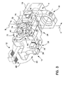
- FIG. 4 An exploded view of clamp assembly 2 is shown in Fig. 4.
- housing portion 32 is separated from housing 34, revealing the detail of the assembly.
- a switch or sensor assembly 94 of the type configured for use in such clamp assemblies is, illustratively, configured to be located in a cavity 96 located in housing 34 for detecting the mechanisms within.
- fluid ports 6, 8 are located on body 10 on the same side relative to mounting bracket 14. This is just an illustrative arrangement, however. Ports 6, 8 do serve to supply fluid to power actuator 4 which is illustratively a piston 98. Including associated fasteners and seals, actuator 4 is disposed in a cavity 100 located in body 10 and is in operative communication with piston rod 78 moving same.
- a cavity 102 and associated bore 104 are disposed in housing 34.
- piston rod 78 is located in, and movable relative to, cavity 102.
- a bore 81 disposed through coupling 80 receives cam pin 76 which extends therethrough, and illustratively couples to a bushing 106 for assistance in sliding within cavity 102.
- Hub 40 extends into bore 104.
- a roller 108 is disposed on cam pin 76, and is positioned such that as cam pin 76 is disposed through cam track 74 of cam member 70, roller 108 provides a friction-reduced contact between cam pin 76 and cam track 74.
- bushing 110 located opposite to bushing 106 on cam pin 76 is bushing 110.
- Bushing 110 is illustratively located in cavity 112 which is illustratively disposed in housing portion 32. (See also Fig. 7.) An illustrative stop 130 which is positioned in a stop locator 132 illustratively disposed in face 134 of housing 34.
- Cavity 112 is shown disposed through housing portion 32 for receiving hub 40.
- hub 40 When assembled, hub 40 extends through cavity 112, allowing attachment of a clamp jaw, illustratively jaw 114, shown in Fig. 4.
- clamp jaw arm 114 is attached to hub 40 via brackets 116 and fasteners 118.
- second clamp arm 120 illustratively attached to housing portion 34 via fasteners 122.
- Housing portion 32 is attached to housing 32 via fasteners 124.
- illustrative housing locators 126 are partially disposed in a portion of housing 34, and configured to assist in proper mating between housing 34 and housing portion 32.
- FIG. 5 shows piston rod 78 in a retracted position with cam pin 76 and roller 108 located at a proximal end 138 of cam track 74.
- cam member 70 is located in such a position that any clamp jaw member attached to hub 40 would be correspondingly located in the closed or clamped position.
- piston rod 78 shown located in an extended position in Fig. 6, cam pin 76 and roller 108 are located at a distal end 140 of cam track 74.
- cam member 70 is located in such a position that any clamp jaw member attached to hub 40 would be correspondingly located in the open position. It is appreciated that clamp 2 may be so configured to operate such that movements of a cam member such as that described herein will produce opposite results with respect to the jaw members opening and closing.
- the illustrated embodiment in Fig. 6 also shows stop 130 limiting the movement of cam member 70 in direction 72.
- Stop 130 illustratively engages a surface portion 144 of cam member 70 to limit its movement.
- stop 130 limits the extent a clamp jaw member can open. It is appreciated that stop 130 and stop locator 132 may be located anywhere relative to a cam member such that the same is restricted in movement as desired by an operator.
- An embodiment of stop 130 is shown in Figs. 8a through d. It is appreciated that the configuration of the stop is for illustrative purposes only, and can be of any configuration suited to limit movement of a jaw assembly.
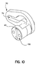
- FIG. 9 A front cross-sectional view of the fluid actuated clamp 2 is shown in Fig. 9.
- Cam member 70 is illustratively located within a chamber 146, which is illustratively formed between housing portions 28 and 32.
- Cam pin 76 is shown disposed through track 74 of cam member 70, coupling 80, roller 108 and bushings 106, 110 located in cavities 102, 112, respectively.
- Cam member 70 comprises a cam track 74 having an alterative configuration from the cam track of the previous embodiment.
- This cam member 70 also comprises a hub 40, also of an alternative configuration from that of the previous embodiment.
- attachment surface 150 is illustratively configured to receive a clamp arm of any appropriate variety.
Landscapes
- Engineering & Computer Science (AREA)
- Mechanical Engineering (AREA)
- Jigs For Machine Tools (AREA)
- Clamps And Clips (AREA)
Applications Claiming Priority (2)
| Application Number | Priority Date | Filing Date | Title |
|---|---|---|---|
| US29605701P | 2001-06-05 | 2001-06-05 | |
| US296057P | 2001-06-05 |
Publications (2)
| Publication Number | Publication Date |
|---|---|
| EP1264663A2 true EP1264663A2 (de) | 2002-12-11 |
| EP1264663A3 EP1264663A3 (de) | 2004-05-12 |
Family
ID=23140418
Family Applications (1)
| Application Number | Title | Priority Date | Filing Date |
|---|---|---|---|
| EP02253908A Withdrawn EP1264663A3 (de) | 2001-06-05 | 2002-06-05 | Spannvorrichtung |
Country Status (1)
| Country | Link |
|---|---|
| EP (1) | EP1264663A3 (de) |
Cited By (2)
| Publication number | Priority date | Publication date | Assignee | Title |
|---|---|---|---|---|
| EP1563957A1 (de) * | 2004-02-13 | 2005-08-17 | DE-STA-CO Metallerzeugnisse GmbH | Antriebsvorrichtung |
| CN102135119A (zh) * | 2011-04-14 | 2011-07-27 | 大连机床集团有限责任公司 | 压紧式油缸结构 |
Citations (4)
| Publication number | Priority date | Publication date | Assignee | Title |
|---|---|---|---|---|
| EP0747172A1 (de) * | 1995-06-06 | 1996-12-11 | Btm Corporation | Kraftverstärker |
| WO1998015392A1 (en) * | 1996-10-07 | 1998-04-16 | Phd, Inc. | Modular stamped parts transfer gripper |
| EP0928663A2 (de) * | 1998-01-07 | 1999-07-14 | ISI Norgren Inc. | Spannvorrichtung mit interner Nockenwirkung |
| EP1201369A2 (de) * | 2000-10-16 | 2002-05-02 | Delaware Capital Formation, Inc. | Angetriebener Spann-Mechanismus |
-
2002
- 2002-06-05 EP EP02253908A patent/EP1264663A3/de not_active Withdrawn
Patent Citations (4)
| Publication number | Priority date | Publication date | Assignee | Title |
|---|---|---|---|---|
| EP0747172A1 (de) * | 1995-06-06 | 1996-12-11 | Btm Corporation | Kraftverstärker |
| WO1998015392A1 (en) * | 1996-10-07 | 1998-04-16 | Phd, Inc. | Modular stamped parts transfer gripper |
| EP0928663A2 (de) * | 1998-01-07 | 1999-07-14 | ISI Norgren Inc. | Spannvorrichtung mit interner Nockenwirkung |
| EP1201369A2 (de) * | 2000-10-16 | 2002-05-02 | Delaware Capital Formation, Inc. | Angetriebener Spann-Mechanismus |
Cited By (2)
| Publication number | Priority date | Publication date | Assignee | Title |
|---|---|---|---|---|
| EP1563957A1 (de) * | 2004-02-13 | 2005-08-17 | DE-STA-CO Metallerzeugnisse GmbH | Antriebsvorrichtung |
| CN102135119A (zh) * | 2011-04-14 | 2011-07-27 | 大连机床集团有限责任公司 | 压紧式油缸结构 |
Also Published As
| Publication number | Publication date |
|---|---|
| EP1264663A3 (de) | 2004-05-12 |
Similar Documents
| Publication | Publication Date | Title |
|---|---|---|
| US7021687B2 (en) | Clamp assembly | |
| US11167427B2 (en) | Gripper with a trident body section | |
| US6378855B1 (en) | Locking pin clamp | |
| US5871250A (en) | Sealed straight line gripper | |
| US6530615B2 (en) | Workpiece gripper | |
| USRE39786E1 (en) | Clamp with improved internal cam action | |
| US7066458B2 (en) | Powered clamp assembly | |
| US6908077B2 (en) | Clamp with swinging and linear motion | |
| US6416045B1 (en) | Rotary clamp having predetermined adjustable clamping angles | |
| US6042166A (en) | Gripper | |
| CA1178311A (en) | Fluid power connector system for manipulator | |
| EP1262285A2 (de) | Spannvorrichtung mit einstellbarem Hub | |
| US6877730B2 (en) | Powered clamp | |
| JP2005074621A (ja) | 角運動式空気式グリッパー | |
| US6666489B2 (en) | Sealed gripper apparatus | |
| EP0313947A2 (de) | Verriegelnde angetriebene Spannvorrichtung | |
| US5762325A (en) | Power actuated gripper | |
| EP2450145A2 (de) | Gelenkklemme | |
| US6641189B2 (en) | Article sensor assembly | |
| EP1368161B1 (de) | Greifer mit einer verstellbaren sensoranordnung | |
| US20030075941A1 (en) | Linear slide gripper | |
| EP1264663A2 (de) | Spannvorrichtung | |
| US7188879B2 (en) | Slide gripper assembly | |
| EP1174226A1 (de) | Abgedichteter Greifer | |
| US10994423B2 (en) | Gripper with a trident body section |
Legal Events
| Date | Code | Title | Description |
|---|---|---|---|
| PUAI | Public reference made under article 153(3) epc to a published international application that has entered the european phase |
Free format text: ORIGINAL CODE: 0009012 |
|
| AK | Designated contracting states |
Kind code of ref document: A2 Designated state(s): AT BE CH CY DE DK ES FI FR GB GR IE IT LI LU MC NL PT SE TR |
|
| AX | Request for extension of the european patent |
Free format text: AL;LT;LV;MK;RO;SI |
|
| PUAL | Search report despatched |
Free format text: ORIGINAL CODE: 0009013 |
|
| AK | Designated contracting states |
Kind code of ref document: A3 Designated state(s): AT BE CH CY DE DK ES FI FR GB GR IE IT LI LU MC NL PT SE TR |
|
| AX | Request for extension of the european patent |
Extension state: AL LT LV MK RO SI |
|
| RIC1 | Information provided on ipc code assigned before grant |
Ipc: 7B 25J 15/02 B Ipc: 7B 25B 5/08 A |
|
| AKX | Designation fees paid | ||
| REG | Reference to a national code |
Ref country code: DE Ref legal event code: 8566 |
|
| STAA | Information on the status of an ep patent application or granted ep patent |
Free format text: STATUS: THE APPLICATION IS DEEMED TO BE WITHDRAWN |
|
| 18D | Application deemed to be withdrawn |
Effective date: 20041113 |