EP1264291B1 - Microsystem using magnetometer and inclinometer for anti-theft protection of valuables - Google Patents
Microsystem using magnetometer and inclinometer for anti-theft protection of valuables Download PDFInfo
- Publication number
- EP1264291B1 EP1264291B1 EP01913992A EP01913992A EP1264291B1 EP 1264291 B1 EP1264291 B1 EP 1264291B1 EP 01913992 A EP01913992 A EP 01913992A EP 01913992 A EP01913992 A EP 01913992A EP 1264291 B1 EP1264291 B1 EP 1264291B1
- Authority
- EP
- European Patent Office
- Prior art keywords
- alert
- message
- processing
- magnetometer
- triggering
- Prior art date
- Legal status (The legal status is an assumption and is not a legal conclusion. Google has not performed a legal analysis and makes no representation as to the accuracy of the status listed.)
- Expired - Lifetime
Links
Images

Classifications
-
- G—PHYSICS
- G08—SIGNALLING
- G08B—SIGNALLING OR CALLING SYSTEMS; ORDER TELEGRAPHS; ALARM SYSTEMS
- G08B13/00—Burglar, theft or intruder alarms
- G08B13/02—Mechanical actuation
- G08B13/14—Mechanical actuation by lifting or attempted removal of hand-portable articles
- G08B13/1436—Mechanical actuation by lifting or attempted removal of hand-portable articles with motion detection
Definitions
- the invention lies in the field of alarm triggering assemblies when it is detected that a normally immobile object, for example an art object exhibited in a museum, moves abnormally. It also relates to a method of assisting the monitoring of a set of objects and an object or set of objects equipped with means for detecting movement and sending messages.
- the patent application RU 2104 554 thus describes a measurement system for determining the pitch and yaw roll speeds of a vehicle.
- the device uses variations in the value of the local terrestrial magnetic field on each of three vehicle-related axes. From these measurements, it is possible to determine the value of pitch and yaw roll speeds of the vehicle. By subtraction of the global rotation speed vector, the global motion vector gives the linear velocity of the vehicle.
- the device relates to a property protection assembly 2a, 2b, 2c which may be, for example, a television set, a calculator, a radio or works of art.
- a property protection assembly 2a, 2b, 2c which may be, for example, a television set, a calculator, a radio or works of art.
- Each of the devices comprises a motion detection assembly 3a, 3b or 3c.
- a message is transmitted by one of the devices 3 to an alarm center 1 which triggers an alarm 12.
- each of the devices 3 comprises a motion detector 9 whose signal is processed by a microprocessor 5 to possibly trigger an alarm through means 4 or a transmitter 7.
- An interface 10 makes it possible to activate or deactivate each of the sets 3. It is indicated in column 3, line 41 that the motion detection means 9 may comprise a ball device.
- a ball 4 is movable inside a coil 3 coiled on a coil body 2.
- Contact terminals 7, 8 can pick up a voltage across the coil 3.
- a processing system consisting of an amplifier 9, a counter 10 or a counter 12 and an alarm trigger 11 can trigger an alarm in case of movement of the object on which the detector is placed or in case of magnetic change due to a displacement of this object.
- the operation is as follows; the ball 4 is made of mild steel and its movements induce changes in the value of the voltage at the terminals 7, 8 of the coil.
- These voltages are amplified by the amplifier 9, the voltage pulses are counted in a counter 10 and the alarm is triggered when a predetermined number of pulses or vibrations is counted.
- the counter 12 makes it possible to count voltage variations due to a distance or a change in the magnetic medium in which the detection assembly is immersed.
- a removal of a magnetic mass or an approximation of such a mass causes variations in the voltage at the terminals 7, 8 which, if they are proved by the counter 12, can trigger the alarm 11.
- These surveillance systems may also include, for example, video sets monitoring by camera the works to be protected. These systems require the presence of an operator to carefully monitor the image or images from each of the cameras. It has also been envisaged magnetic marking systems in which a magnetic resonator is included in the the work to watch. The passage of the work containing the resonator through a gantry receiving a frequency corresponding to the resonance frequency of the resonator can detect the passage of the work. Such devices assume that the protected work will go through the portico. Implantable microchips, infrared curtains, mercury ball contactors, piezoelectric devices, accelerometers have also been envisaged. These systems could be satisfactory if the false alarm rate was not as important.
- the present invention is a new device for detecting a movement of the protected object, with a very low rate of false alarm.
- the present invention relates to a device for detecting an abnormal movement, that is to say different from the "invisible" movements of an object considered immobile, a protected work. It aims a device generating a false alarm rate very low or zero. It aims at a device aimed at limiting the quantity and the vigilance of the surveillance personnel. It aims at a device aimed at limiting the quantity and the vigilance of the surveillance personnel. It also aims to detect a theft or attempted theft from the beginning of the offense.
- the invention relates to a set of triggering an alert or a pre-alert, as defined by claim 1.
- the signals emitted by the magnetometer (s) and possibly other sensor means such as an inclinometer are digital.
- the filtering can be performed in the form of Kalman filtering to reduce the convergence time of the processing algorithm and to determine a moving average value taking into account the temporal evolution of the received values.
- the detection means further comprise one or more inclinometers with one or more axes mechanically secured to the object to be protected and coupled to the processing means.
- the device further comprises one or more additional magnetometers mechanically secured to the object, connected to the processing means.
- the device may comprise a generator of a magnetic field, for example, random. This generator is coupled to the processing means so that they are able to permanently determine the parameters defining a local magnetic field vector.
- the distribution of the means constituting the alarm trigger assembly may vary.
- the means attached to the object may comprise the measurement means, the measurement transmission means, the processing means and the message transmission means.
- the means for transmitting the measured values to the means for processing the measured values may consist of a single connection, for example a wired connection.
- the warning triggering means of the station monitoring are coupled to the processing means via the message transmitting means and message receiving means.
- the means attached to the object comprise only the measuring means and the means for transmitting the measured values.
- the means for transmitting the measurements include the message transmission means.
- the alert tripping means are coupled to the processing means by a single connection for example wire.
- the invention also relates to a method of monitoring an object or set of objects as defined by claim 10.
- the real movement of the object can be much more complex than a simple rotation, it can then be interesting, to reduce the rate of error, to detect a succession of rotations that constitute this movement.
- the magnitudes to be compared will then be calculated from a multicomponent vector quantity.
- the presence message is constituted by the message transmitting the measurement values of the measuring means.
- the presence and alert messages are transmitted in the form of a free electromagnetic wave.
- the transmission of the alert message is done on a frequency different from the transmission frequency of the presence message.
- the presence and alert messages include an identification code of the monitored object and / or a location of the monitored object.
- the alert transmission means are standard means IR, video etc.
- an alert causes the appearance of at least one reported image of the object on a screen of a monitor of the monitoring station.
- the image is said to be indicated in this way, that the monitor, showing the image, is indicated for example by a blinking of a lamp associated with the monitor or by an audible signal.
- the station can count means measuring a rotational movement of the object, these means being mechanically integral with the object, for example one or more one or more axis magnetometers, optionally associated with one or more inclinometers one or more axes, means for transmission of presence message and warning message, these means being coupled to processing means coupled to the means for measuring a rotation of the object.
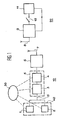
- a device comprises, on the one hand, means 10 fixed to the object together constituting a detection station of the object to be protected and, on the other hand, receiving and triggering means 20 alarm, constituting together at least a portion of a monitoring station, coupled to different objects to be protected.
- the detection means attached to the object comprise, on the one hand, a magnetometer 1 coupled by measurement transmission means 15, for example a wire link, to processing means 5, these processing means being coupled to means transmitting message 6 transmitting via an antenna or other means 7 a message to a monitoring station 20, disposed near or objects to monitor.
- the means attached to the object comprise a power supply source 30 coupled to the constituent elements of these fixed means. This source may be a battery, a microbattery, a cell for transforming an electromagnetic wave into an electric current or any other known means.
- the monitoring station 20 comprises, on the one hand, a message receiving station 9 coupled via a switch 12 to an alarm sending means 11.
- the alarm sending means 11 is coupled in return on the station 9 so as to allow after alert an acknowledgment function, for example, by resetting the alarm trigger.
- the communication means between the detection station 10 and the warning station 20 have been represented in the form of an antenna 7 coupled to the message transmission means 6 of the detection station and an antenna 8 coupled to the receiving means 9 of the monitoring station 20.
- These antennas assume that the connection between the detection station 10 and the warning station 20 is in the form of an electromagnetic link.
- This mode of embodiment is the preferred mode. It is obvious, however, that the connection between the receiving station 20 and detection and transmission 10 can be performed by any other means of connection known in particular, a wired link or an infrared link.
- the signal processing means 5 comprise, on the one hand, means 3 for processing the signal of the magnetometer 1 and, on the other hand, means 4 for filtering this signal and for detecting the movement.
- the means 3 receive the data coming from the magnetometer 1 and process these data to form at least one rotation vector, or at least one component of this vector, of the magnetometer 1 with respect to the local magnetic field of the object.
- This rotation vector is then filtered by the filtering means 4, for example, a Kalman filter or from a so-called “maximum likelihood” technique or any algorithm relating to the detection / estimation in information theory, for detect a rotation amplitude greater than a fixed threshold and trigger a message in case the detected rotation has an amplitude greater than the threshold.
- the filtering means 4 for example, a Kalman filter or from a so-called “maximum likelihood” technique or any algorithm relating to the detection / estimation in information theory, for detect a rotation amplitude greater than a fixed threshold and trigger a message in case the detected rotation has an amplitude greater than the threshold.
- the magnetometer one or more axes 1 continuously measures the magnetic field present on each of these axes.
- the value of the magnetic field present on each of the axes is sent continuously to the processing means 3.
- the processing means 3 generate on receipt of each set of values from the magnetometer 1 the value of a rotation vector of the magnetic field captured by each axis of the magnetometer 1 relative to the natural magnetic field or not surrounding the object to be detected.
- the object is in principle immobile, this immobility is not complete.
- the object is subjected to the natural seismic noise of the building of implantation of the object.
- the object is subject to any vibrations due to the activity around the object and around the building where the magnetometer 1 is fixed to the object.
- the natural local magnetic field around the magnetometer 1 may vary in particular due to changes in the magnetic conditions around this magnetometer induced in particular by the passage of visitors.
- Other reasons for mobility of the object and therefore the magnetometer may be due to the nature of the object.
- the table according to its mode of attachment can be sensitive to drafts causing slight local movements of the fabric and possibly the frame of the table.
- weather conditions can induce large transient variations in the local magnetic field, especially in the event of a magnetic storm.
- the rotation vector calculated by the processing means 3 is filtered in filtering and detection means 4. These means make it possible to determine an adaptive average value of the noise of the vector rotation of the magnetometer. This adaptive average value is multiplied by a false alarm safety factor to provide an adaptive threshold. When the value of the rotation vector exceeds the adaptive threshold thus fixed, the filtering and detection means 4 change their logic state which constitutes a message for the message transmission means 6.
- the transmission means 6 emit, of Preferably, permanently a message in the direction of the receiving station 9. When no amplitude rotation greater than the threshold is detected, the message is a presence message. When a rotation greater than the predetermined threshold is detected, an alert message is immediately transmitted.
- the presence and alert messages comprise a set of identification signals of the object on which the device 10 is fixed and / or the location of the object in the monitored enclosure, for example, the Museum.
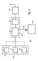
- the device 40 for measuring a rotation further comprises an inclinometer 2 connected to the processing means 3.
- the processing means 3 elaborate the rotation vector of the object taking into account the data coming from on the one hand, the magnetometer and, on the other hand, the inclinometer. This device makes decoying rotation detection even more difficult.
- the device represented in figure 2 comprises one or more additional magnetometers 1 'distributed over the surface of the object to be protected and / or in the immediate vicinity. These magnetometers 1 'are connected to the processing means 3. With this set of magnetometers 1, 1' it is possible to calculate a value and a direction of the magnetic field with respect to a reference trihedron linked to the object to be protected. When this field undergoes rotations or changes in its average time value with respect to this trihedron, this modification is detected by the measuring and treatment and filtering means 5 which, in this case, must be adapted to this function, and an alert message is issued.
- the invention may include a magnetic field generator 13.
- This generator permanently or randomly causes a magnetic field which is intended to facilitate the calculation of a modification of the magnetic field due to the presence of an external metal object.
- the generator 13 also causes a local variation of the magnetic field so that the local magnetic field vector varies in the space in modulus and direction. It thus becomes possible to detect any movement of rotation and / or translation.
- the characteristics of the magnetic field caused by the generator 13 are transmitted by a link 14 to the calculation means 3.
- the processing means 3 and 4 are located on the side of the object. These processing means can also be arranged on the side of the monitoring station as shown figure 3 .
- the measuring means 40 composed of one or more magnetometers 1, 1 'as in the previous case and possibly inclinometers 2 are coupled to a transmitter 6.
- the processing means 3, 4 are These means 3, 4 are directly coupled to the warning trigger 11.
- This version may comprise, like the previous versions, a magnetic field generator 13 which is in this case coupled to the means 3, 4 of the invention. located on the side of the monitoring station.
- This version of the invention operates as the previous one.
- the presence message is this time obligatory. It consists of measurement transmissions. An absence of such a transmission will trigger a particular message of the processing means 3, 4 by triggering alert 11.
- An alert message is a message different from a presence message.
- the alert message further contains a code whose reception at the monitoring station triggers the alert.
- the code can be constituted by a simple change of the transmission frequency.
- the device described in connection with the Figures 1 to 3 has been described as an isolated device inside an enclosure. It is obvious that, especially in a museum, the objects to be protected are not isolated and that there may be several thousand objects to protect in a small volume enclosure. There is therefore a problem of managing the presence and alert messages for all the objects to be protected contained in the enclosure.
- the links between the transmission means 6 and the receiving means 9 are point-to-point links, for example wired or infrared, it is possible to identify the object by the source of the message received on the receiving means.
- the connection between the transmission means 6 and the reception means 9 is electromagnetic, there is a problem of frequency management.
- This problem can be solved, either by frequency allocation to each of the objects, or by time distribution, programmed or random, of the emission slots of each object, or else by a combination of the two methods, that is to say ie allocation of different frequencies and distribution of transmission slots for each of the frequencies.
Description
L'invention se situe dans le domaine des ensembles de déclenchement d'alerte lorsqu'il est détecté qu'un objet normalement immobile, par exemple un objet d'art exposé dans un musée, bouge de manière anormale. Elle est également relative à un procédé d'aide à la surveillance d'un ensemble d'objets et à un objet ou ensemble d'objets équipés de moyens de détection de mouvement et d'envoi de messages.The invention lies in the field of alarm triggering assemblies when it is detected that a normally immobile object, for example an art object exhibited in a museum, moves abnormally. It also relates to a method of assisting the monitoring of a set of objects and an object or set of objects equipped with means for detecting movement and sending messages.
Des dispositifs pour mesurer des mouvements de mobiles comme par exemple des avions, des fusées, ou des véhicules spatiaux sont connus. La demande de brevet
De nombreux dispositifs ont déjà été mis en oeuvre pour détecter des vols, des tentatives de vols ou des actes de malveillance sur des objets normalement immobiles comme par exemple des objets exposés dans des musées.Many devices have already been implemented to detect theft, theft or malicious acts on normally immobile objects such as objects exhibited in museums.
Ainsi par exemple, la demande de brevet
Le dispositif concerne un ensemble de protection de biens 2a, 2b, 2c qui peuvent être par exemple, un poste de télévision, un calculateur, une radio ou des objets d'art. Chacun des dispositifs comporte un ensemble de détection de mouvements 3a, 3b ou 3c. Lorsqu'un mouvement est détecté un message est transmis par l'un des dispositifs 3 à une centrale d'alarme 1 qui déclenche une alarme 12.The device relates to a property protection assembly 2a, 2b, 2c which may be, for example, a television set, a calculator, a radio or works of art. Each of the devices comprises a motion detection assembly 3a, 3b or 3c. When a movement is detected, a message is transmitted by one of the
En référence à la
Le document
Dans un espace fermé par un ensemble 5, 6 non magnétique, une boule 4 est mobile à l'intérieur d'une bobine 3 enroulée sur un corps de bobine 2. Des bornes de contact 7, 8 permettent de capter une tension aux bornes de la bobine 3. Un système de traitement composé d'un amplificateur 9, d'un compteur 10 ou d'un compteur 12 et d'un déclencheur d'alarme 11 permet de déclencher une alarme en cas de mouvement de l'objet sur lequel le détecteur est posé ou en cas de changement magnétique dû à un déplacement de cet objet. Le fonctionnement est le suivant ; la boule 4 est en acier doux et ses déplacements induisent des changements dans la valeur de la tension aux bornes 7, 8 de la bobine. Ces tensions sont amplifiées par l'amplificateur 9, les impulsions de tension sont comptées dans un compteur 10 et l'alarme est déclenchée lorsqu'un nombre prédéterminé d'impulsions ou de vibrations est compté. En parallèle, le compteur 12 permet de compter des variations de tension dues à un éloignement ou à un changement du milieu magnétique dans lequel baigne l'ensemble de détection. Ainsi, un éloignement d'une masse magnétique ou un rapprochement d'une telle masse provoque des variations de la tension aux bornes 7, 8 qui, si elles sont avérées par le compteur 12, permettent de déclencher l'alarme 11.In a space closed by a
- Ces systèmes de surveillance peuvent comprendre aussi, par exemple des ensembles vidéo surveillant par caméra les oeuvres à protéger. Ces systèmes nécessitent la présence d'un opérateur pour surveiller attentivement l'image ou les images en provenance de chacune des caméras. Il a été également envisagé des systèmes de marquage magnétique dans lesquels un résonateur magnétique est inclus dans le l'oeuvre à surveiller. Le passage de l'oeuvre contenant le résonateur au travers d'un portique recevant une fréquence correspondant à la fréquence de résonance du résonateur permet de détecter le passage de l'oeuvre. De tels dispositifs supposent que l'oeuvre protégée va passer par le portique. Il a été envisagé également des puces électroniques implantables, des rideaux infrarouges, des contacteurs à billes de mercure, des dispositifs piézoélectriques, des accéléromètres. Ces systèmes pourraient donner satisfaction si le taux de fausses alarmes n'était pas aussi important.These surveillance systems may also include, for example, video sets monitoring by camera the works to be protected. These systems require the presence of an operator to carefully monitor the image or images from each of the cameras. It has also been envisaged magnetic marking systems in which a magnetic resonator is included in the the work to watch. The passage of the work containing the resonator through a gantry receiving a frequency corresponding to the resonance frequency of the resonator can detect the passage of the work. Such devices assume that the protected work will go through the portico. Implantable microchips, infrared curtains, mercury ball contactors, piezoelectric devices, accelerometers have also been envisaged. These systems could be satisfactory if the false alarm rate was not as important.
La présente invention est un nouveau dispositif permettant de détecter un mouvement de l'objet protégé, avec un très faible taux de fausse alarme.The present invention is a new device for detecting a movement of the protected object, with a very low rate of false alarm.
- La présente invention a pour objet un dispositif permettant de détecter un mouvement anormal, c'est-à-dire différent des mouvements « invisibles » d'un objet considéré comme immobile, d'une oeuvre protégée. Elle vise un dispositif générant un taux de fausses alarmes très faible, voire nul. Elle vise un dispositif visant à limiter la quantité et la vigilance du personnel de surveillance. Elle vise un dispositif visant à limiter la quantité et la vigilance du personnel de surveillance. Elle vise aussi à détecter un vol ou une tentative de vol dès le début de l'infraction.The present invention relates to a device for detecting an abnormal movement, that is to say different from the "invisible" movements of an object considered immobile, a protected work. It aims a device generating a false alarm rate very low or zero. It aims at a device aimed at limiting the quantity and the vigilance of the surveillance personnel. It aims at a device aimed at limiting the quantity and the vigilance of the surveillance personnel. It also aims to detect a theft or attempted theft from the beginning of the offense.
Dans un mode de réalisation particulier, elle vise aussi à détecter l'approche d'un objet métallique, par exemple, un objet tranchant. Dans un autre mode de réalisation particulier, elle vise à identifier immédiatement l'objet protégé faisant l'objet de la tentative de vol. A toutes ces fins, l'invention est relative à un ensemble de déclenchement d'une alerte ou d'une pré-alerte, tel que défini par la revendication 1.In a particular embodiment, it also aims to detect the approach of a metal object, for example, a sharp object. In another particular embodiment, it aims to identify immediately the protected object being the object of the attempted theft. For all these purposes, the invention relates to a set of triggering an alert or a pre-alert, as defined by claim 1.
Dans un mode de réalisation avantageux, les signaux émis par le ou les magnétomètres et éventuellement d'autres moyens capteurs tel qu'un inclinomètre, sont numériques. Le filtrage peut être réalisé sous la forme d'un filtrage de Kalman destiné à réduire le temps de convergence de l'algorithme de traitement et à déterminer une valeur moyenne mobile tenant compte de l'évolution temporelle des valeurs reçues. Dans une version visant à réduire les possibilités de leurrage du dispositif, les moyens de détection comportent en outre un ou plusieurs inclinomètres à un ou plusieurs axes solidaires mécaniquement de l'objet à protéger et couplés aux moyens de traitement. Dans une version améliorée visant à détecter non seulement les mouvements de l'objet mais de plus un changement des conditions magnétiques autour de l'objet provoqué par exemple par l'approche d'un objet métallique le dispositif comporte, en outre, un ou plusieurs magnétomètres supplémentaires mécaniquement solidaires de l'objet, connectés aux moyens de traitement. Dans une version destinée à diminuer encore les possibilités de leurrage, le dispositif peut comprendre un générateur d'un champ magnétique, par exemple, aléatoire. Ce générateur étant couplé aux moyens de traitement de façon à ce que ceux-ci soient à même de déterminer en permanence les paramètres définissant un vecteur champ magnétique local.In an advantageous embodiment, the signals emitted by the magnetometer (s) and possibly other sensor means such as an inclinometer, are digital. The filtering can be performed in the form of Kalman filtering to reduce the convergence time of the processing algorithm and to determine a moving average value taking into account the temporal evolution of the received values. In a version designed to reduce the possibility of decoying the device, the detection means further comprise one or more inclinometers with one or more axes mechanically secured to the object to be protected and coupled to the processing means. In an improved version intended to detect not only the movements of the object but also a change in the magnetic conditions around the object caused for example by the approach of a metallic object the device further comprises one or more additional magnetometers mechanically secured to the object, connected to the processing means. In a version intended to further reduce the possibilities of decoying, the device may comprise a generator of a magnetic field, for example, random. This generator is coupled to the processing means so that they are able to permanently determine the parameters defining a local magnetic field vector.
Suivant les applications, la répartition des moyens composant l'ensemble de déclenchement d'alerte, peut varier. Les moyens fixés à l'objet peuvent comprendre les moyens de mesure, les moyens de transmission des mesures, les moyens de traitement et les moyens d'émission de message. Dans ce cas, les moyens de transmission des valeurs mesurées vers les moyens de traitement des valeurs mesurées peuvent être constitués par une simple liaison par exemple filaire. Les moyens de déclenchement d'alerte de la station de surveillance sont couplés aux moyens de traitement par l'intermédiaire des moyens d'émission de message et des moyens de réception de message. Dans une version simplifiée, les moyens fixés à l'objet ne comportent que les moyens de mesure et les moyens de transmission des valeurs mesurées. Dans ce cas, les moyens de transmission des mesures incluent les moyens d'émission de message. Les moyens de déclenchement d'alerte sont couplés aux moyens de traitement par une simple liaison par exemple filaire.Depending on the applications, the distribution of the means constituting the alarm trigger assembly may vary. The means attached to the object may comprise the measurement means, the measurement transmission means, the processing means and the message transmission means. In this case, the means for transmitting the measured values to the means for processing the measured values may consist of a single connection, for example a wired connection. The warning triggering means of the station monitoring are coupled to the processing means via the message transmitting means and message receiving means. In a simplified version, the means attached to the object comprise only the measuring means and the means for transmitting the measured values. In this case, the means for transmitting the measurements include the message transmission means. The alert tripping means are coupled to the processing means by a single connection for example wire.
L'invention est également relative à un procédé de surveillance d'un objet ou d'un ensemble d'objets tel que défini par la revendication 10.The invention also relates to a method of monitoring an object or set of objects as defined by
Le mouvement réel de l'objet peut être beaucoup plus complexe qu'une simple rotation, il pourra alors être intéressant, pour diminuer le taux d'erreur, de détecter une succession de rotations qui constituent ce mouvement. Les grandeurs à comparer seront alors calculées à partir d'une grandeur vectorielle à plusieurs composantes.The real movement of the object can be much more complex than a simple rotation, it can then be interesting, to reduce the rate of error, to detect a succession of rotations that constitute this movement. The magnitudes to be compared will then be calculated from a multicomponent vector quantity.
Dans une version plus sophistiquée destinée en particulier à prévoir le cas où l'alimentation électrique des moyens situés du côté de l'objet serait en panne ou aurait été neutralisée, on peut en outre émettre en permanence un message de présence et déclencher l'alerte s'il y a eu réception d'un message d'alerte ou en l'absence de message de présence pendant une durée supérieure à une durée déterminée. Dans le cas où du côté de l'objet seuls les moyens de mesures et les moyens de transmission de mesures sont présents, le message de présence est constitué par le message transmettant les valeurs de mesures des moyens de mesure.In a more sophisticated version intended in particular to provide the case where the power supply electrical means located on the side of the object would be out of order or would have been neutralized, it is also possible to continuously transmit a presence message and to trigger the alert if an alert message has been received or the absence of a presence message for a duration greater than a specified duration. In the case where on the side of the object only the measurement means and the measurement transmission means are present, the presence message is constituted by the message transmitting the measurement values of the measuring means.
De préférence, les messages de présence et d'alerte sont transmis sous forme d'onde électromagnétique libre. De préférence, l'émission du message d'alerte se fait sur une fréquence différente de la fréquence d'émission du message de présence.Preferably, the presence and alert messages are transmitted in the form of a free electromagnetic wave. Preferably, the transmission of the alert message is done on a frequency different from the transmission frequency of the presence message.
Dans le mode de réalisation préféré, les messages de présence et d'alerte comportent un code d'identification de l'objet surveillé et/ou d'un emplacement de l'objet surveillé. De préférence également, les moyens d'émission d'alerte sont des moyens standards IR, vidéo etc.In the preferred embodiment, the presence and alert messages include an identification code of the monitored object and / or a location of the monitored object. Also preferably, the alert transmission means are standard means IR, video etc.
De préférence, une alerte provoque l'apparition d'au moins une image signalée de l'objet sur un écran d'un moniteur de la station de surveillance. L'image est dite signalée en ce sens, que le moniteur, montrant l'image, est indiqué par exemple par un clignotement d'une lampe associée au moniteur ou par un signal sonore.Preferably, an alert causes the appearance of at least one reported image of the object on a screen of a monitor of the monitoring station. The image is said to be indicated in this way, that the monitor, showing the image, is indicated for example by a blinking of a lamp associated with the monitor or by an audible signal.
Enfin, l'invention est relative à une station de détection telle que définie par la revendication 9. La station peut compter des moyens de mesure d'un mouvement de rotation de l'objet, ces moyens étant mécaniquement solidaires de l'objet, par exemple un ou plusieurs magnétomètres un ou plusieurs axes, associés éventuellement à un ou plusieurs inclinomètres un ou plusieurs axes, des moyens d'émission de message de présence et de message d'alerte, ces moyens étant couplés à des moyens de traitement couplés aux moyens de mesure d'une rotation de l'objet.Finally, the invention relates to a detection station as defined by
L'invention et des variantes de réalisation seront maintenant décrites à l'aide des dessins annexés
dans lesquels :
- la
figure 1 , représente un schéma d'un dispositif selon l'invention ; - la
figure 2 , représente des variantes de l'exemple de réalisation représenté enfigure 1 , - la
figure 3 représente d'autres variantes de réalisation.
wherein :
- the
figure 1 represents a diagram of a device according to the invention; - the
figure 2 , represents variants of the exemplary embodiment shown infigure 1 , - the
figure 3 represents other embodiments.
En référence à la
Les moyens de détection fixés à l'objet comportent d'une part, un magnétomètre 1 couplé par des moyens de transmission de mesure 15, par exemple une liaison filaire, à des moyens de traitement 5, ces moyens de traitement étant couplés à des moyens d'émission de message 6 émettant par l'intermédiaire d'une antenne ou d'un autre moyen 7 un message en direction d'une station de surveillance 20, disposée à proximité de ou des objets à surveiller. Les moyens fixés à l'objet comportent une source d'alimentation électrique 30 couplée aux éléments constitutifs de ces moyens fixes. Cette source peut être une pile, une microbatterie, une cellule de transformation d'une onde électromagnétique en courant électrique ou tout autre moyen connu. La station de surveillance 20 comporte d'une part, une station de réception de messages 9 couplée par l'intermédiaire d'un interrupteur 12 à un moyen d'émission d'alarme 11. Le moyen d'émission d'alarme 11 est couplé en retour sur la station 9 de façon à permettre après alerte une fonction d'acquittement, par exemple, par remise à zéro du déclenchement d'alerte.The detection means attached to the object comprise, on the one hand, a magnetometer 1 coupled by measurement transmission means 15, for example a wire link, to processing means 5, these processing means being coupled to
Sur la
Le magnétomètre un ou plusieurs axes 1 mesure en permanence le champ magnétique présent sur chacun de ces axes. La valeur du champ magnétique présent sur chacun des axes est envoyée en permanence aux moyens de traitement 3. Les moyens de traitement 3 élaborent au reçu de chaque ensemble de valeurs en provenance du magnétomètre 1 la valeur d'un vecteur rotation du champ magnétique capté par chacun des axes du magnétomètre 1 par rapport au champ magnétique naturel ou non entourant l'objet à détecter. Bien que l'objet soit en principe immobile, cette immobilité n'est pas complète. D'une part, l'objet est soumis au bruit sismique naturel du bâtiment d'implantation de l'objet. D'autre part, l'objet est soumis à d'éventuelles vibrations dues à l'activité autour de l'objet et autour du bâtiment où se trouve le magnétomètre 1 fixé à l'objet. Enfin, le champ magnétique local naturel autour du magnétomètre 1 peut varier notamment en raison de modifications des conditions magnétiques autour de ce magnétomètre induites notamment par le passage de visiteurs. D'autres raisons de mobilité de l'objet et donc du magnétomètre peuvent être dues à la nature de l'objet. Par exemple s'il s'agit d'un tableau, le tableau selon son mode d'accrochage peut être sensible à des courants d'air entraînant de légers mouvements locaux de la toile et éventuellement du cadre du tableau. Enfin, les conditions météorologiques peuvent induire des variations passagères importantes du champ magnétique local en particulier en cas d'orage magnétique. Pour toutes ces raisons, il peut être préférable plutôt que de fixer un seuil fixe de vecteur rotation a priori, de tenir compte d'un moyen de filtrage des variations locales du vecteur rotation dues à tous les phénomènes transitoires et parasites qui viennent d'être cités. C'est pourquoi dans le mode préféré de réalisation le vecteur rotation calculé par les moyens de traitement 3 est filtré dans des moyens de filtrage et détection 4. Ces moyens permettent de déterminer une valeur moyenne adaptative du bruit du vecteur rotation du magnétomètre. Cette valeur moyenne adaptative est multipliée par un coefficient de sécurité de fausse alarme pour fournir un seuil adaptatif. Lorsque la valeur du vecteur rotation dépasse le seuil adaptatif ainsi fixé, les moyens de filtrage et de détection 4 changent d'état logique ce qui constitue un message pour les moyens d'émission de message 6. Les moyens d'émission 6 émettent, de préférence, en permanence de façon périodique un message en direction de la station de réception 9. Lorsqu'aucune rotation d'amplitude supérieure au seuil n'est détectée, le message est un message de présence. Lorsqu'une rotation supérieure au seuil prédéterminée est détectée, il y a émission immédiate d'un message d'alerte.The magnetometer one or more axes 1 continuously measures the magnetic field present on each of these axes. The value of the magnetic field present on each of the axes is sent continuously to the processing means 3. The processing means 3 generate on receipt of each set of values from the magnetometer 1 the value of a rotation vector of the magnetic field captured by each axis of the magnetometer 1 relative to the natural magnetic field or not surrounding the object to be detected. Although the object is in principle immobile, this immobility is not complete. On the one hand, the object is subjected to the natural seismic noise of the building of implantation of the object. On the other hand, the object is subject to any vibrations due to the activity around the object and around the building where the magnetometer 1 is fixed to the object. Finally, the natural local magnetic field around the magnetometer 1 may vary in particular due to changes in the magnetic conditions around this magnetometer induced in particular by the passage of visitors. Other reasons for mobility of the object and therefore the magnetometer may be due to the nature of the object. For example if it is a table, the table according to its mode of attachment can be sensitive to drafts causing slight local movements of the fabric and possibly the frame of the table. Finally, weather conditions can induce large transient variations in the local magnetic field, especially in the event of a magnetic storm. For all these reasons, it may be preferable rather than setting a fixed threshold of vector rotation a priori, to take into account a means of filtering local variations of the rotation vector due to all the transient and parasitic phenomena that have just been cited. Therefore, in the preferred embodiment, the rotation vector calculated by the processing means 3 is filtered in filtering and detection means 4. These means make it possible to determine an adaptive average value of the noise of the vector rotation of the magnetometer. This adaptive average value is multiplied by a false alarm safety factor to provide an adaptive threshold. When the value of the rotation vector exceeds the adaptive threshold thus fixed, the filtering and detection means 4 change their logic state which constitutes a message for the message transmission means 6. The transmission means 6 emit, of Preferably, permanently a message in the direction of the receiving
Avantageusement, les messages de présence et d'alerte comportent un ensemble de signaux d'identification de l'objet sur lequel le dispositif 10 est fixé et/ou de l'emplacement de l'objet dans l'enceinte surveillée, par exemple, le musée. Dans une version améliorée représentée
Une version encore améliorée sera maintenant commentée en liaison avec la
Dans cette figure, les éléments ayant même fonction que dans l'exemple de réalisation représenté
Dans ce cas, les moyens de mesure 40 composés d'un ou plusieurs magnétomètres 1, 1' comme dans le cas précédent et éventuellement d'inclinomètres 2 sont couplés à un émetteur 6. Dans ce cas, les moyens de traitement 3, 4 sont placés en aval d'un récepteur 9. Ces moyens 3, 4 sont directement couplés au déclencheur d'alerte 11. Cette version peut comporter comme les versions précédentes un générateur 13 de champ magnétique qui est dans ce cas couplé aux moyens 3, 4 de traitement situés du côté de la station de surveillance. Cette version de l'invention fonctionne comme la précédente. Le message de présence est cette fois obligatoire. Il est constitué par les transmissions de mesure. Une absence d'une telle transmission déclenchera un message particulier des moyens de traitement 3, 4 au moyen de déclenchement d'alerte 11. Un message d'alerte est un message différent d'un message de présence. Alors que le message de présence peut ne comporter qu'une identification, le message d'alerte contient de plus un code dont la réception au niveau de la station de surveillance déclenche l'alerte. Le code peut être constitué par un simple changement de la fréquence d'émission. Le dispositif décrit en liaison avec les
Ce problème pourra être résolu, soit par allocation de fréquence à chacun des objets, soit par répartition dans le temps, programmée ou aléatoire, des créneaux d'émission de chaque objet, soit encore par combinaison des deux méthodes, c'est-à-dire allocation de différentes fréquences et répartition de créneaux d'émission pour chacune des fréquences.This problem can be solved, either by frequency allocation to each of the objects, or by time distribution, programmed or random, of the emission slots of each object, or else by a combination of the two methods, that is to say ie allocation of different frequencies and distribution of transmission slots for each of the frequencies.
Claims (10)
- Device for triggering an alert or a pre-alert when it is detected that a normally immobile object moves, this assembly comprising:- measurement means (40) generating measured values,- means (5) of transmitting measured values to means (3, 4, 5) of processing the measured values,- message transmission means (6),- monitoring means (20) comprising:- message reception means (9),.- means of triggering the alert (11),in which:- the measurement means (40) comprise at least one magnetometer (1) with one or several axes fixed to the object and measuring the magnetic field along at least one axis,- the processing means (3, 4, 5) calculate a vector magnitude representative of a movement and if generate a movement detection signal by the calculated vector magnitude is greater than a threshold vector magnitude, based on a series of measurements from the measurement means (40),- the means of triggering the alert being coupled to means of processing measurements (3, 4, 5) and sending an alert message on reception of the detection signal from the said measurement processing means (3, 4, 5).
- Assembly for triggering an alert according to claim 1, characterized in that the threshold vector magnitude is a predetermined magnitude.
- Assembly for triggering an alert according to claim 1, characterized in that the threshold vector magnitude is a variable magnitude as a function of an adaptive value calculated from the most recently measured vector magnitudes.
- Alert assembly according to one of claims 1 to 3, characterized in that the processing means (3, 4, 5) are located at a distance from the object.
- Alert assembly according to one of claims 1 to 3, characterized in that the means (3, 4, 5) of processing the measurements are on the object.
- Alert assembly according to claim 5,
characterized in that the measurement means (40) fixed to the object also comprise one or several inclinometers (2) with one or several axes. - Measurement assembly according to one of claims 5 or 6, characterized in that the means (6, 7) of transmitting a message also periodically send a presence message.
- Alert assembly according to one of claims 1 to 7, characterized in that the processing means (3, 4, 5) comprise a Kalman filter.
- Detection station for detecting that a monitored object, normally motionless, moves, said station being affixed to said object and comprising at least one magnetometer (1) with one or several axes, fixed to the object, means (3, 4, 5) of processing the measured value from the magnetometers (1, 1') to detect a rotation movement of the object and to transmit a detection signal, message transmission means (6, 7) coupled to the processing means (3, 4, 5) to send an alert message on reception of the detection signal.
- Process for monitoring an object or a set of objects in which each object communicates with a monitoring station, according to which at the object end:- the values of the magnetic field on at least one axis with a magnetometer with one or several axis fixed to the object,- at least one vector magnitude representation of a rotation movement greater than a threshold is detected from a series of measurements of the magnetometer,- a presence message is continuously and periodically transmitted as long as there is no detection,- at least an absence message is transmitted as soon as a vector magnitude representative of a rotation movement greaer than a given threshold is detected, and- an alert is triggered at the end of the monitoring station if a standard alert message is received or if no presence message was received during a time exceeding a given duration.
Applications Claiming Priority (3)
| Application Number | Priority Date | Filing Date | Title |
|---|---|---|---|
| FR0003237A FR2806506B1 (en) | 2000-03-14 | 2000-03-14 | MAGNETOMETRIC AND INCLINOMETRIC MICROSYSTEM FOR MONITORING VALUE OBJECTS |
| FR0003237 | 2000-03-14 | ||
| PCT/FR2001/000740 WO2001069561A1 (en) | 2000-03-14 | 2001-03-13 | Microsystem using magnetometer and inclinometer for anti-theft protection of valuables |
Publications (2)
| Publication Number | Publication Date |
|---|---|
| EP1264291A1 EP1264291A1 (en) | 2002-12-11 |
| EP1264291B1 true EP1264291B1 (en) | 2010-06-16 |
Family
ID=8848052
Family Applications (1)
| Application Number | Title | Priority Date | Filing Date |
|---|---|---|---|
| EP01913992A Expired - Lifetime EP1264291B1 (en) | 2000-03-14 | 2001-03-13 | Microsystem using magnetometer and inclinometer for anti-theft protection of valuables |
Country Status (5)
| Country | Link |
|---|---|
| US (1) | US6882275B2 (en) |
| EP (1) | EP1264291B1 (en) |
| DE (1) | DE60142390D1 (en) |
| FR (1) | FR2806506B1 (en) |
| WO (1) | WO2001069561A1 (en) |
Families Citing this family (54)
| Publication number | Priority date | Publication date | Assignee | Title |
|---|---|---|---|---|
| FR2826127B1 (en) * | 2001-06-19 | 2003-09-26 | Commissariat Energie Atomique | TELESURVEILLANCE INSTALLATION AND METHOD USING THE INSTALLATION |
| US20060068754A1 (en) * | 2004-09-30 | 2006-03-30 | Helena Goldfarb | System and method for securing a large infrastructure |
| US8092251B2 (en) * | 2007-12-29 | 2012-01-10 | Apple Inc. | Active electronic media device packaging |
| EP2898489B1 (en) * | 2012-09-18 | 2019-10-09 | Vootner Goushe LLC | Sensor system for protection of artworks and other valuable objects |
| KR101710666B1 (en) * | 2012-12-12 | 2017-02-27 | 한국전자통신연구원 | Apparatus and Method for Monitoring Complex Slope based on Wireless Network |
| US9245432B2 (en) | 2013-08-15 | 2016-01-26 | Xiao Hui Yang | EAS tag utilizing magnetometer |
| US9910105B2 (en) | 2014-03-20 | 2018-03-06 | Lockheed Martin Corporation | DNV magnetic field detector |
| US9638821B2 (en) | 2014-03-20 | 2017-05-02 | Lockheed Martin Corporation | Mapping and monitoring of hydraulic fractures using vector magnetometers |
| US9823313B2 (en) | 2016-01-21 | 2017-11-21 | Lockheed Martin Corporation | Diamond nitrogen vacancy sensor with circuitry on diamond |
| US9853837B2 (en) | 2014-04-07 | 2017-12-26 | Lockheed Martin Corporation | High bit-rate magnetic communication |
| US10168393B2 (en) | 2014-09-25 | 2019-01-01 | Lockheed Martin Corporation | Micro-vacancy center device |
| US9835693B2 (en) | 2016-01-21 | 2017-12-05 | Lockheed Martin Corporation | Higher magnetic sensitivity through fluorescence manipulation by phonon spectrum control |
| US10520558B2 (en) | 2016-01-21 | 2019-12-31 | Lockheed Martin Corporation | Diamond nitrogen vacancy sensor with nitrogen-vacancy center diamond located between dual RF sources |
| US9910104B2 (en) | 2015-01-23 | 2018-03-06 | Lockheed Martin Corporation | DNV magnetic field detector |
| US9614589B1 (en) | 2015-12-01 | 2017-04-04 | Lockheed Martin Corporation | Communication via a magnio |
| GB2540308B (en) | 2014-04-07 | 2018-05-16 | Lockheed Corp | Energy efficient controlled magnetic field generator circuit |
| WO2016118756A1 (en) | 2015-01-23 | 2016-07-28 | Lockheed Martin Corporation | Apparatus and method for high sensitivity magnetometry measurement and signal processing in a magnetic detection system |
| EP3248021A4 (en) * | 2015-01-23 | 2018-12-12 | Lockheed Martin Corporation | Dnv magnetic field detector |
| EP3250887A4 (en) | 2015-01-28 | 2018-11-14 | Lockheed Martin Corporation | Magnetic navigation methods and systems utilizing power grid and communication network |
| WO2016122965A1 (en) | 2015-01-28 | 2016-08-04 | Lockheed Martin Corporation | In-situ power charging |
| WO2016126436A1 (en) | 2015-02-04 | 2016-08-11 | Lockheed Martin Corporation | Apparatus and method for recovery of three dimensional magnetic field from a magnetic detection system |
| GB2550809A (en) | 2015-02-04 | 2017-11-29 | Lockheed Corp | Apparatus and method for estimating absolute axes' orientations for a magnetic detection system |
| EP3371614A1 (en) | 2015-11-04 | 2018-09-12 | Lockheed Martin Corporation | Magnetic band-pass filter |
| WO2017087014A1 (en) | 2015-11-20 | 2017-05-26 | Lockheed Martin Corporation | Apparatus and method for hypersensitivity detection of magnetic field |
| WO2017087013A1 (en) | 2015-11-20 | 2017-05-26 | Lockheed Martin Corporation | Apparatus and method for closed loop processing for a magnetic detection system |
| WO2017123261A1 (en) | 2016-01-12 | 2017-07-20 | Lockheed Martin Corporation | Defect detector for conductive materials |
| WO2017127094A1 (en) | 2016-01-21 | 2017-07-27 | Lockheed Martin Corporation | Magnetometer with light pipe |
| GB2562193B (en) | 2016-01-21 | 2021-12-22 | Lockheed Corp | Diamond nitrogen vacancy sensor with common RF and magnetic fields generator |
| WO2017127097A1 (en) | 2016-01-21 | 2017-07-27 | Lockheed Martin Corporation | Magnetometer with a light emitting diode |
| WO2017127098A1 (en) | 2016-01-21 | 2017-07-27 | Lockheed Martin Corporation | Diamond nitrogen vacancy sensed ferro-fluid hydrophone |
| WO2017127079A1 (en) | 2016-01-21 | 2017-07-27 | Lockheed Martin Corporation | Ac vector magnetic anomaly detection with diamond nitrogen vacancies |
| US9953503B2 (en) | 2016-02-23 | 2018-04-24 | Honeywell International Inc. | Door and window contact systems and methods that include MEMS accelerometers and MEMS magnetometers |
| US10408890B2 (en) | 2017-03-24 | 2019-09-10 | Lockheed Martin Corporation | Pulsed RF methods for optimization of CW measurements |
| US20170343621A1 (en) | 2016-05-31 | 2017-11-30 | Lockheed Martin Corporation | Magneto-optical defect center magnetometer |
| US10345395B2 (en) | 2016-12-12 | 2019-07-09 | Lockheed Martin Corporation | Vector magnetometry localization of subsurface liquids |
| US10330744B2 (en) | 2017-03-24 | 2019-06-25 | Lockheed Martin Corporation | Magnetometer with a waveguide |
| US10677953B2 (en) | 2016-05-31 | 2020-06-09 | Lockheed Martin Corporation | Magneto-optical detecting apparatus and methods |
| US10371765B2 (en) | 2016-07-11 | 2019-08-06 | Lockheed Martin Corporation | Geolocation of magnetic sources using vector magnetometer sensors |
| US10281550B2 (en) | 2016-11-14 | 2019-05-07 | Lockheed Martin Corporation | Spin relaxometry based molecular sequencing |
| US10527746B2 (en) | 2016-05-31 | 2020-01-07 | Lockheed Martin Corporation | Array of UAVS with magnetometers |
| US10145910B2 (en) | 2017-03-24 | 2018-12-04 | Lockheed Martin Corporation | Photodetector circuit saturation mitigation for magneto-optical high intensity pulses |
| US10274550B2 (en) | 2017-03-24 | 2019-04-30 | Lockheed Martin Corporation | High speed sequential cancellation for pulsed mode |
| US10317279B2 (en) | 2016-05-31 | 2019-06-11 | Lockheed Martin Corporation | Optical filtration system for diamond material with nitrogen vacancy centers |
| US10571530B2 (en) | 2016-05-31 | 2020-02-25 | Lockheed Martin Corporation | Buoy array of magnetometers |
| US10228429B2 (en) | 2017-03-24 | 2019-03-12 | Lockheed Martin Corporation | Apparatus and method for resonance magneto-optical defect center material pulsed mode referencing |
| US10359479B2 (en) | 2017-02-20 | 2019-07-23 | Lockheed Martin Corporation | Efficient thermal drift compensation in DNV vector magnetometry |
| US10345396B2 (en) | 2016-05-31 | 2019-07-09 | Lockheed Martin Corporation | Selected volume continuous illumination magnetometer |
| US10338163B2 (en) | 2016-07-11 | 2019-07-02 | Lockheed Martin Corporation | Multi-frequency excitation schemes for high sensitivity magnetometry measurement with drift error compensation |
| US10459041B2 (en) | 2017-03-24 | 2019-10-29 | Lockheed Martin Corporation | Magnetic detection system with highly integrated diamond nitrogen vacancy sensor |
| US10371760B2 (en) | 2017-03-24 | 2019-08-06 | Lockheed Martin Corporation | Standing-wave radio frequency exciter |
| US10379174B2 (en) | 2017-03-24 | 2019-08-13 | Lockheed Martin Corporation | Bias magnet array for magnetometer |
| US10338164B2 (en) | 2017-03-24 | 2019-07-02 | Lockheed Martin Corporation | Vacancy center material with highly efficient RF excitation |
| US10147289B2 (en) | 2017-04-05 | 2018-12-04 | Ut-Battelle, Llc | Magnetic field sensing for tamper-indicating devices |
| DE102020216530A1 (en) * | 2020-12-23 | 2022-06-23 | Continental Automotive Gmbh | Tachograph system for a motor vehicle, motor vehicle and method for operating a tachograph system |
Family Cites Families (14)
| Publication number | Priority date | Publication date | Assignee | Title |
|---|---|---|---|---|
| US3611345A (en) * | 1969-04-16 | 1971-10-05 | Intron Int Inc | Motion detector |
| US3781664A (en) * | 1972-10-24 | 1973-12-25 | Develco | Magnetic detection for an anti-shoplifting system utilizing combined magnetometer and gradiometer signals |
| DE2430710A1 (en) * | 1974-06-26 | 1976-01-15 | Honeywell Gmbh | Positioner change sensor - responds to rotation about at least one axis and protects objects against unauthorised removal |
| DE2802075C3 (en) * | 1978-01-18 | 1980-11-13 | Compur-Electronic Gmbh, 8000 Muenchen | Procedures for security and surveillance, in particular for personal security and surveillance, as well as an arrangement for the implementation of the procedure |
| EP0097742B1 (en) * | 1982-06-28 | 1987-09-23 | Jerome Hal Lemelson | Theft detection system and method |
| IT1181336B (en) * | 1984-04-03 | 1987-09-23 | Mario Coppola | DEVICE SUITABLE TO DETECT THE INCLINATION CHANGES |
| US5331561A (en) * | 1992-04-23 | 1994-07-19 | Alliant Techsystems Inc. | Active cross path position correlation device |
| US5376921A (en) * | 1992-11-30 | 1994-12-27 | Trikilis; Emmanuel M. | Security system employing magnetization and detection |
| FR2729239B1 (en) * | 1995-01-10 | 1997-04-04 | Sgs Thomson Microelectronics | THEFT PROTECTION SYSTEM |
| US5910774A (en) * | 1996-09-18 | 1999-06-08 | Itron, Inc. | Sensor for count and tamper detection |
| US6150810A (en) * | 1997-03-24 | 2000-11-21 | Bechtel Bwxt Idaho, Llc | Method for detecting the presence of a ferromagnetic object using maximum and minimum magnetic field data |
| FR2765372B1 (en) * | 1997-06-27 | 1999-09-03 | Val Protect Sa | MOTION DETECTION SENSOR AND MOTION DETECTION DEVICE COMPRISING SAME |
| GB9813889D0 (en) * | 1998-06-27 | 1998-08-26 | Secr Defence | Apparatus for detecting metals |
| US6310549B1 (en) * | 2000-08-29 | 2001-10-30 | Digitech International | Wireless security system |
-
2000
- 2000-03-14 FR FR0003237A patent/FR2806506B1/en not_active Expired - Fee Related
-
2001
- 2001-03-13 EP EP01913992A patent/EP1264291B1/en not_active Expired - Lifetime
- 2001-03-13 US US10/220,632 patent/US6882275B2/en not_active Expired - Lifetime
- 2001-03-13 WO PCT/FR2001/000740 patent/WO2001069561A1/en active Application Filing
- 2001-03-13 DE DE60142390T patent/DE60142390D1/en not_active Expired - Lifetime
Also Published As
| Publication number | Publication date |
|---|---|
| US6882275B2 (en) | 2005-04-19 |
| FR2806506B1 (en) | 2003-07-18 |
| DE60142390D1 (en) | 2010-07-29 |
| FR2806506A1 (en) | 2001-09-21 |
| WO2001069561A1 (en) | 2001-09-20 |
| EP1264291A1 (en) | 2002-12-11 |
| US20030076229A1 (en) | 2003-04-24 |
Similar Documents
| Publication | Publication Date | Title |
|---|---|---|
| EP1264291B1 (en) | Microsystem using magnetometer and inclinometer for anti-theft protection of valuables | |
| EP2232298B1 (en) | Equipment for detecting persons in a defined space | |
| EP2727099B1 (en) | Warning system for advising of dangerous situations in an aggressive setting | |
| EP0748492B1 (en) | Method and device for sensing, identifying and protecting goods, particularly from theft | |
| FR3052902B1 (en) | ALARM SENSOR, SYSTEM COMPRISING SUCH SENSOR, AND METHOD OF USING SAID ALARM SYSTEM | |
| EP2336990B1 (en) | Silent antitheft protection system for goods shown to the public | |
| WO2013110684A1 (en) | System for detecting an intrusion attempt inside a perimeter defined by a fence | |
| CA2573641A1 (en) | Tire, wheel or tire and wheel assembly equipped with a device for counting number of rotations | |
| EP3158343B1 (en) | Energy-efficient home-automation device and method for tracking the displacement of a monitored object | |
| EP3287402B1 (en) | Connected electricity transport cable reel | |
| EP0252801B1 (en) | Detection device for an electromagnetic pulse, especially due to a nuclear explosion | |
| EP1092615A1 (en) | Device for monitoring parked objects, with antitheft means | |
| EP0681723B1 (en) | Tamperproof radio anti-jamming device for trespass monitoring systems | |
| FR2901902A1 (en) | Overhead cable e.g. overhead power transmission line, theft attempt detecting and warning device for central intervention center, has alarm detection, analyzing and teletransmission unit, and continuous wire fixed to cable and ground | |
| WO2007051955A1 (en) | Device for monitoring a sensitive object such as an aircraft and method for operating this device | |
| FR2768249A1 (en) | Search/surveillance mechanism | |
| FR2585846A1 (en) | Device for location and/or identification by means of an emitter card | |
| WO2002011096A1 (en) | Method and device for continuous protection against intrusion in possibly inhabited premises | |
| FR2720178A1 (en) | Theft protection system for electronic and electrical appliances | |
| FR2851680A1 (en) | Structure monitoring device, e.g. for antenna tower, has transmitter unit sending alarm signal if wind force exceeds preset value or shifting of foundations is detected | |
| EP0428432B1 (en) | Self-adjusting ultrasonic anti-theft device | |
| FR3048578A1 (en) | COMMUNICATING DEVICE, COMMUNICATION SYSTEM, ALARM CENTRAL, AND COMMUNICATION METHOD | |
| EP0411234A1 (en) | Electronic system for automatic surveillance | |
| FR2702069A1 (en) | Device for securing a casing and a camera | |
| EP3432298A1 (en) | Electronic display device, related electronic display system and building, such as a shopping center, comprising such a display system |
Legal Events
| Date | Code | Title | Description |
|---|---|---|---|
| PUAI | Public reference made under article 153(3) epc to a published international application that has entered the european phase |
Free format text: ORIGINAL CODE: 0009012 |
|
| 17P | Request for examination filed |
Effective date: 20020816 |
|
| AK | Designated contracting states |
Kind code of ref document: A1 Designated state(s): AT BE CH CY DE DK ES FI FR GB GR IE IT LI LU MC NL PT SE TR |
|
| RBV | Designated contracting states (corrected) |
Designated state(s): DE GB IT |
|
| 17Q | First examination report despatched |
Effective date: 20050414 |
|
| RAP1 | Party data changed (applicant data changed or rights of an application transferred) |
Owner name: COMMISSARIAT A L'ENERGIE ATOMIQUE |
|
| 17Q | First examination report despatched |
Effective date: 20050414 |
|
| GRAP | Despatch of communication of intention to grant a patent |
Free format text: ORIGINAL CODE: EPIDOSNIGR1 |
|
| RAP1 | Party data changed (applicant data changed or rights of an application transferred) |
Owner name: COMMISSARIAT A L'ENERGIE ATOMIQUE ET AUX ENERGIES |
|
| GRAS | Grant fee paid |
Free format text: ORIGINAL CODE: EPIDOSNIGR3 |
|
| GRAA | (expected) grant |
Free format text: ORIGINAL CODE: 0009210 |
|
| AK | Designated contracting states |
Kind code of ref document: B1 Designated state(s): DE GB IT |
|
| REF | Corresponds to: |
Ref document number: 60142390 Country of ref document: DE Date of ref document: 20100729 Kind code of ref document: P |
|
| PLBE | No opposition filed within time limit |
Free format text: ORIGINAL CODE: 0009261 |
|
| STAA | Information on the status of an ep patent application or granted ep patent |
Free format text: STATUS: NO OPPOSITION FILED WITHIN TIME LIMIT |
|
| 26N | No opposition filed |
Effective date: 20110317 |
|
| REG | Reference to a national code |
Ref country code: DE Ref legal event code: R097 Ref document number: 60142390 Country of ref document: DE Effective date: 20110316 |
|
| PGFP | Annual fee paid to national office [announced via postgrant information from national office to epo] |
Ref country code: GB Payment date: 20180316 Year of fee payment: 18 Ref country code: DE Payment date: 20180309 Year of fee payment: 18 |
|
| PGFP | Annual fee paid to national office [announced via postgrant information from national office to epo] |
Ref country code: IT Payment date: 20180309 Year of fee payment: 18 |
|
| REG | Reference to a national code |
Ref country code: DE Ref legal event code: R119 Ref document number: 60142390 Country of ref document: DE |
|
| GBPC | Gb: european patent ceased through non-payment of renewal fee |
Effective date: 20190313 |
|
| PG25 | Lapsed in a contracting state [announced via postgrant information from national office to epo] |
Ref country code: DE Free format text: LAPSE BECAUSE OF NON-PAYMENT OF DUE FEES Effective date: 20191001 Ref country code: GB Free format text: LAPSE BECAUSE OF NON-PAYMENT OF DUE FEES Effective date: 20190313 |
|
| PG25 | Lapsed in a contracting state [announced via postgrant information from national office to epo] |
Ref country code: IT Free format text: LAPSE BECAUSE OF NON-PAYMENT OF DUE FEES Effective date: 20190313 |