EP1263105A1 - Dispositif d'angle plat ou de dérivation pour goulottes - Google Patents
Dispositif d'angle plat ou de dérivation pour goulottes Download PDFInfo
- Publication number
- EP1263105A1 EP1263105A1 EP02291321A EP02291321A EP1263105A1 EP 1263105 A1 EP1263105 A1 EP 1263105A1 EP 02291321 A EP02291321 A EP 02291321A EP 02291321 A EP02291321 A EP 02291321A EP 1263105 A1 EP1263105 A1 EP 1263105A1
- Authority
- EP
- European Patent Office
- Prior art keywords
- support
- base
- cover
- bases
- plate
- Prior art date
- Legal status (The legal status is an assumption and is not a legal conclusion. Google has not performed a legal analysis and makes no representation as to the accuracy of the status listed.)
- Withdrawn
Links
Images


Classifications
-
- H—ELECTRICITY
- H02—GENERATION; CONVERSION OR DISTRIBUTION OF ELECTRIC POWER
- H02G—INSTALLATION OF ELECTRIC CABLES OR LINES, OR OF COMBINED OPTICAL AND ELECTRIC CABLES OR LINES
- H02G3/00—Installations of electric cables or lines or protective tubing therefor in or on buildings, equivalent structures or vehicles
- H02G3/02—Details
- H02G3/06—Joints for connecting lengths of protective tubing or channels, to each other or to casings, e.g. to distribution boxes; Ensuring electrical continuity in the joint
- H02G3/0608—Joints for connecting non cylindrical conduits, e.g. channels
Definitions
- the present invention relates to a flat angle or bypass device to have at least two sections of trunking between the bases forming between them an angle in the same plane, said device comprising, on the one hand, a plate having a connection bottom of the funds of said bases and to at least two side walls located on at least two edges of said bottom of connection, and, on the other hand, a cover to be reported on said plate above said connection bottom.
- the flat angle device or bypass has a cover or seal per compartment which forms a flat angle and a cover or counter-joint element which covers the assembly seals positioned on each of the compartments of the trunking bases to connected.
- the present invention provides a new flat angle or bypass device whose installation is simple on the trunking sections, which allows access to certain compartments of said sections of chute without possibility of access to other compartments and which minimizes the number of parts used for the closing of the angled part joining the two sections of chute.
- the present invention relates to a corner device flat or bypass as defined in the introduction, characterized in that it comprises at least one support to be attached to one of said bases, between the wings side of this base or between one of its side wings and a partition of fractionation carried by the bottom of said base, this support comprising means for mounting the cover and being intended to support the cut end a section of cover for closing said base or a compartment thereof last, and in that at least one of said side walls of said plate carries, on its internal face, means for supporting at least one section of closing cover of the other of said bases or of a compartment thereof base, so that said sections of closure cover of the two bases extend above the connection bottom of said plate and thus participate in its closure, the cover being adapted to cover the said sections of closure cover placed on said bases.
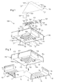
- FIG 1 there is shown a flat angle or bypass device 100 to have between the bases 10 at least two sections of chute forming between them an angle, here a right angle, in the same plane (see Figure 3).
- each base 10 of chute section comprises, in a manner known per se, a profile substantially U-shaped with a bottom 11 and two lateral wings 14, 15 parallel, each of the wings side 14, 15 comprising, at its free end, a return 16, 17 directed towards inside the base 10.
- the returns 16, 17 of the side wings 14, 15 of each base 10 are directed towards each other.
- Each return 16, 17 of each lateral wing 14, 15 is formed into a longitudinal groove with, on the outside of this groove, a latching notch for snap-on mounting of a section of closure cover 140 (see figure 5) or 140 '(see figure 11).
- each base carries longitudinal ribs 19 parallel for the possible assembly of one or more partitions of fractionation 150 (see Figure 9) or separation.
- the flat angle or bypass device 100 shown in the different figures includes a plate 110 having a bottom of connection 111 of the bottoms 11 of said bases 10 and at least two walls side 114, 115 located on at least two edges of said connection bottom 111.
- the side walls 114, 115 of the plate 110 each have, overall, a profile similar to the profile of the lateral wings 14, 15 of the bases 10 trunking sections to be connected, and are placed at right angles to the edges exterior of said connection base 111 of the plate 110 to establish the junction between the lateral wings 14, 15 outside of the bases 10 of the sections of trunking to be connected.
- each side wall 114, 115 of the plate 110 carries, on its internal face, support means 118, 118 ', 117 of the same section of closure cover 140; 140 'suitable for closing one of said bases 10 (see Figure 6) or a compartment thereof (see Figure 10).
- the means for supporting the side wall 114 of the plate 110 here include two studs 118, 118 'spaced from each other and the face of which upper constitutes a bearing face of an end portion of the section of closure cover 140; 140 'concerned (see Figures 5, 6, and 10, 11).
- the means for supporting the other side wall 115 of the plate 110 here include a hook 117 carried by the internal face of this side wall 115 and in which engages a longitudinal tab 140a; 140'a of a stretch of closure cover 140; 140 'of said base 10 (see FIG. 5) or of a compartment of the latter (see Figure 10).
- the side wall 114 of the plate 110 also carries, on its internal face, support means, constituted here by a groove means 116 associated with stud 118, which make it possible to support a longitudinal edge of a closure cover section 140 ′ of a compartment of a base 10 of a trunking section to be connected (see Figures 9 and 11).
- connection bottom 111 of the plate 110 has oblong openings 111 a through which are introduced fixing screws (not shown) for fixing the plate 110 on the support wall (not shown) supporting the bases 10 of the sections of trunking to be connected.
- connection base 111 of the plate 110 carries plates 119 extending perpendicular to said connecting bottom 111 and arranged two by two at right angles to the extension of the ribs 19 carried by the bottoms 11 of the bases 10 of the trunking sections to be connected (see FIG. 3). These plates 119 are each intended to support the part of each partition of fractionation 150 which extends beyond each base 10 on the bottom of connection 111 of plate 110 (see figures 10 and 11).
- connection bottom 111 of the plate 110 has two free edges 112, 113 arranged at right angles and each intended to abut on a cut edge 12 of a bottom 11 of a base 10 of trunk section to be connected.
- Each free edge 112, 113 projecting two flexible tabs 112a, 113a suitable, during the positioning of the plate 110 between the two bases 10, to be positioned on either side of a rib 19 carried by the bottom 11 of the corresponding base 10, here the central rib 19 of said base 10, for adjust the width positioning of said plate 110 relative to each said bases 10.
- connection bottom 111 of the plate 110 has two breakable parts arranged at right angles, each breakable part being delimited between each free edge 112, 113 and a breakable line 112 ', 113'.
- Each breakable line 112 ', 113' is parallel to each free edge 112, 113 of the connection bottom 111 of the plate 110.
- said plate 110 can be adapted to a width that is smaller by chute base.
- connection bottom On each of the breakable lines 112 ', 113' from the bottom 111 connecting plates 110 are provided tabs 112'a, 113'a projecting from said connection bottom.
- These tabs 112'a, 113'a are identical to the flexible tabs 112a, 113a projecting from the free edges 112, 113 of the connection bottom 111, so that, when the section is cut connection bottom 111 in order to remove the breakable parts, we find the same arrangement of tabs 112'a, 113'a carried by the new edges free 112 ', 113' of said connecting bottom 111 of smaller width.
- the flat angle or bypass device 100 also includes a support 120 to be attached to one of said bases 10, between the lateral wings 14, 15 of this base 10 (see FIG. 5) or between one of its lateral wings 15 and a partition wall 150 carried by the bottom 11 of said base (see Figure 11).
- This support 120 is intended to support the cut end edge 140c; 140 ° C. a section of closure cover 140; 140 'of said base 10 or of a compartment of the latter.
- the support 120 is in the form of a bar carrying, at its ends free, latching means 121 on the returns 16, 17 of the side wings 14, 15 of the base 10 of the trough section concerned (see FIG. 5) or on the returns 17, 153 of a side wing 15 and of a partition 150 of this base 10 (see Figure 11).
- the latching means 121 are identical or similar to the means for snap-fastening the cover cover sections 140; 140 'and here include a tab 121a intended to engage in the groove formed by the return of the side wing concerned from the base 10 and a latching tooth 121b intended to snap onto a heel extending under said groove.
- the face 122 of the support 120 carries a plurality of studs 126 distributed over the entire length of the support 120.
- Each stud 126 is arranged transversely to the longitudinal direction of the support 120 and has an end 126a which forms a stop for the cut end edge 140c; 140'c of a cover section closing 140; 140 ′ of the base 10 on which the support 120 is attached, or a compartment of this base 10.
- the slice 121c of latching means 121 is slightly set back from the ends 126a pads 126 so that only the ends 126a of the pads 126 constitute stops for the cut end edge 140c; 140'c of the cover section closure 140; 140 'correspondent.
- the support 120 has a groove 123, which extends over one of its longitudinal sides, and which is capable of receiving a longitudinal tab 140a; 140'a carried by the closing section 140; 140 'from the other base 10 (by relative to that on which said support 120 is attached) or of a compartment this last.
- the position of the support 120 on said base 10 is determined, since it must be located at the end of it, at the junction with said plate 110, so that the groove 123 of said support extends in the extension of the groove formed by the return 16 of the lateral wing 14 corresponding to the other base 10 disposed at right angles.
- the support 120 advantageously consists of separable modules 120A, 120B, 120C, 120D and each separable module 120A, 120B, 120C, 120D has, at its end furthest from another adjacent separable module, means latching 121 of the type of those previously described, for its latching on the return 16, 153 of a side wing 14 or of a bulkhead splitting 150 of the base 10.
- the support 120 however includes a basic module 120E attached to a separable module 120D, this basic module 120E being positioned furthest inside the angle formed by the bases 10 of trunking sections with respect to to other separable modules.
- This basic 120E module has two ends, said latching means 121 on the returns 16, 17 of the wings lateral 14, 15 of said base or on the returns 17, 153 of a lateral wing 15 and a partition wall 150 of this base 10.
- the support 120 also comprises, at a free end, intended for be positioned within the angle formed between the bases 10 of sections of trunking to be connected, at the junction between the two lateral wings 14, 15 inside of said corresponding bases 10, two drooping edges 127 arranged at right angles and able to establish the junction between the lateral wings 14, 15 inside the bases 10.
- FIGS. 2a to 2d there is shown a variant of the support 120 shown in FIGS. 2a to 2d, according to which the external face 122 of the support 120 instead of studs 126 have ribs 126 'distributed over the entire length of the support and each extending transversely to the longitudinal direction of said support 120, the end 126'a of each rib 126 'constituting a stop for the cut end edge 140c; 140'c of a cover section closure 140; 140 '.
- the latching means 121 are slightly different and here include a snap tab intended to snap under the corresponding return of the side wing concerned of the base of the section of trunking to be connected or under the return of the installed partition wall on said base.
- the flat angle or bypass device 100 shown more particularly in Figure 1 further comprises a cover 130 to be reported on the plate 110 above its connection bottom 111.
- this cover 130 is generally in the form of a plate asymmetrical in shape with an oblique edge, a straight edge and an end edge free 134.
- additional mounting means which include, as appropriate typical shown, on the one hand, on said support 120, a well 124 and a housing latching 125 located on the base module 120E of said support 120 and which lead to the external face 122 of the latter, and, on the other hand, to the face internal of the cover 130, a turret 132 intended to engage in the well 124 and a latching tooth 133 intended to be introduced into the housing 125 to snap onto an internal edge 125a of the latter (see Figure 8C).
- the cover 130 is advantageously adapted to cover the sections closure cover 140; 140 'installed on the bases 10, these closure cover sections 140; 140 'extending above the bottom of connection 111 of plate 110 to participate in closing the angle located between the two bases 10 of trunking sections to be connected, and therefore at the closing of plate 110.
- the cover 130 has at one end, located opposite its edge free end 134, two drooping edges 131 arranged at right angles and suitable for establish the junction between the lateral wings 14, 15 inside of said bases 10.
- the side walls 114, 115 of the plate 110 include a flange 114a intended to cover the free end edge 134 of the cover 130 for hold the latter on said plate 110 by pressing it against the external face of the corresponding closure cover section 140.
- the cover 130 comprises, near its free end edge 134, two parts breakable 130a, 130b arranged at right angles and whose width corresponds to the width of the breakable parts of the connection bottom 111 of the plate 110, so that the length of the cover can be adapted to the width of the bottom of connection 111 of the plate 110 in order to implement the device flat angle or bypass 100 for a smaller section base width chute.
- the different parts of the flat angle device or bypass 100 i.e. the plate 110, the support 120 and the cover 130, are each individually made in one piece, advantageously by molding of a plastic material.
- each of the bases 10 of sections of trunking to be connected is positioned on the support wall (not shown) to form here an angle equal to about 90 °. Then, the plate 110 is placed between the two bases so that the free edges 112, 113 of the bottom of connection 111 thereof abutting on the cut edges 12 of the bases 10, the positioning of the plate 110 being guided by the flexible tabs 112a, 113a which are caught on either side of each of the ribs 19 power stations carried by the funds 11 of said bases 10.
- the plate 110 of the flat angle or bypass device is fixed by fixing screw (not shown) on said support wall (not shown).
- the plate 110 allows a tolerance for example of more or less 10 mm of positioning of the bases 10 between them.
- the side walls 114, 115 of said plate cover the end of the lateral wings 14, 15 outside of the bases 10, the connection base 111 of the plate establishing continuity between the bottoms 11 of the bases 10.
- the plates 119 carried by the bottom of connection 111 of the plate 110 extend in the extension of the ribs 19 carried by the bottoms 11 of said bases 10.
- the ends of said plates 119 are here located at a distance from the ends of said ribs 19, this distance being created by the breakable parts of the connection bottom 111 of plate 110.
- the support 120 is attached to a of said bases 10, by being snapped onto the returns 16, 17 of the lateral wings 14, 15 of this base 10 using its latching means 121.
- the support 120 is positioned at the end of the base 10, so that that its drooping edges 127 arranged at right angles establish the junction between the lateral wings 14, 15 inner of the bases 10 and that its longitudinal groove, not referenced in Figure 5, is located in the extension of the groove formed by the return 16 of the lateral wing 14 of the base 10 on which the support 120.
- closure cover sections 140 are attached to each of the bases 10 of trunking sections to be connected.
- a section of closure cover 140 is attached to the base 10 not supporting the support 120, being snapped in by its means latching 140a, 140b on the returns 16, 17 of the side wings 14, 15 of this base 10, and it extends above the connection bottom 111 of the plate 110 to close the angle between the bases 10 by coming to bear on the faces upper studs 118, 118 ′ carried by the internal face of the side wall 114 of plate 110.
- a longitudinal tab 140a of this section of cover of closure 140 located outside the angle formed between said bases 10, engages in the hook 117 carried by the other side wall 115 of the plate 110 so as to be supported by it.
- this section of closure cover 140 is positioned rigidly on the plate 110, the mechanical rigidity of the assembly being very good.
- closure cover section 140 to be mounted on the base 10 on which is attached the support 120 is positioned so as to snap by its latching means 140a, 140b on the returns 16, 17 of the wings side 14, 15 of said base, its cut end edge 140c coming position on the external face of the support 120 in abutment against the studs 126 carried by it (see Figure 6).
- the external face 122 of the support 120 is located at a level lower than that of the closure cover section 140, only the studs 126 being located at the cut end edge 140c thereof.
- the cover 130 is attached to the plate 110 so as to cover the cover sections of closure 140 and support 120, to perfect the aesthetics of the whole and ensure good insulation at the angle formed between the bases 10 of trunking sections to be connected.
- the drooping edges 131 arranged at the square of the cover 130 ensure continuity between the lateral wings 14, 15 inside the bases 10 trunking sections to be connected.
- the implementation cover 130 is made by tilting the latter from the outside towards the inside of the angle formed between the bases 10. To do this, the edge free end 134 of the cover 130 is taken under the rim 114a carried by the side walls 114, 115 of the plate 110, and the cover 130 is tilted in direction of the bases 10, so that the falling edges 131 of said cover 130 are positioned against the lateral wings 14, 15 interior corresponding bases 10.
- the turret 132 and the latching tooth 133 thereof engages in the well 124 and the corresponding snap-in housing 125 of the support 120 so that the cover 130 is snapped onto the support and wedged, at its free end edge 134, by the rim 114a of the plate.
- the cover 130 is held rigidly on the assembly constituted by the plate 110 and the support 120.
- the installer can later intervene in a of the two bases 10 without opening the other. For this, it suffices to remove the cover 130 and removes the closure cover section 140 considered.
- the angle formed between the two bases 10 is closed by one of the sections of closing cover of one of said bases, which minimizes the number of parts used.
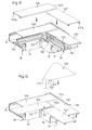
- the bases 10 are positioned in the same way as those shown in Figure 3, and the plate 110 is also positioned in the same way between these bases 10.
- each of the partition walls 150 is attached to each of the bottoms 11 of the bases 10 being snapped on by its foot 151 on each central rib 19 carried by each bottom 11 of each base 10 (see figure 10).
- each partition 150 extending also beyond each base 10 on the connection bottom 111 of the plate 110, while being held at its foot 151 by said plates 119, and, in this way, the continuity of the different compartments of said bases 10 is provided at the angle formed between them.
- a first section of closure lid 140 'of the compartment outside of the base 10 not supporting the support 120 is mounted between the return 17 of the lateral side wing 15 of this base 10 and the return 153 of the bulkhead fractionation 150 carried by said base 10, so that part of this closure cover section 140 'extends above the bottom of connection 111 of the plate 110 to come into abutment against the upper face stud 118 'of the side wall 114 of the plate 110.
- This cover section 140 ' is also supported by the hook 117 on the other wall side 115 of plate 110.
- a second section of closure cover 140 ′ is put in place on the external compartment of the base 10 intended to support the support 120, between the return 16 of the lateral lateral wing 14 of this base 10 and the return 153 of the partition wall 150 carried by this base 10, so that a part of this section of closure cover 140 'extends above the bottom of connection 111 of the plate 110 while being supported by the upper face of the stud 118 and by means of groove 116 of the side wall 114 of the plate 110.
- the longitudinal tab 140'a of the cover section of closure 140 corresponding engages in the groove means 116 carried by said side wall 114 of the plate 110, this groove means 116 extending the groove formed by the return 16 of the corresponding side wing 14 of the base 10 concerned.
- each of the bases 10 of trunking sections to be connected are therefore extended at the level of the plate and individually closed by the closing cover sections 140 'correspondents.
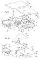
- the support 120 is placed on a base 10 at its interior compartment not yet closed, at the junction between the base 10 and the plate 110.
- this support 120 is shortened in length by removing two 120A, 120B separable modules. It is reported between the return 17 of the wing 15 and the return 153 of the partition wall 150 of the base 10, so that its drooping edges 127 arranged at right angles ensure the continuity between the upper parts of the inner side wings 15, 14 of the bases 10.
- a first section of closure cover 140 ′ is put in place on the base 10 not supporting the support 120, between the inner side wing 14 of this and its partition 150. This section of the cover closure 140 'is also engaged in the groove 123 of the support 120 for be supported over its entire length.
- a second section of closure cover 140 ' is put in place between the side wing 15 located inside the corner of the base 10 on which is attached the corresponding support 120 and the partition 150 carried by this base, so that its end edge cut 140'c comes to bear on the support 120 while being in abutment against the ends free 126a of the pads 126 thereof.
- each of the compartments extends to level of the angle and is closed individually by the cover sections of closure 140.
- the cover 130 is attached to plate 110 to cover all of the cover sections 140 'and the support and establish the junction between the wings side 14, 15 inside of the bases 10 (see Figure 13).
- the cover 130 is put in place in the same way as that described previously with reference to Figures 8a to 8c.
- FIGS. 15 and 16 two main stages of the installation between the two bases 10 of trunking sections of the variant of the flat angle or bypass device 100 comprising the support 120 shown in Figure 14.
- Figures 15 and 16 correspond in all points to Figures 5 and 6, put apart from the use of a slightly different support 120. We will then refer, for the description of these Figures 15 and 16, to that of Figures 5 and 6, in considering that the support 120 used is now that shown on the figure 14.
Abstract
Description
- ledit support est situé du côté intérieur de l'angle formé par les socles desdits tronçons de goulotte ;
- le support se présente sous la forme d'une barrette portant, à ses extrémités libres, des moyens d'encliquetage sur les retours des ailes latérales du socle du tronçon de goulotte ou sur les retours d'une aile latérale et d'une cloison de fractionnement de ce socle ;
- la face externe du support porte au moins un plot disposé transversalement à la direction longitudinale dudit support et dont une extrémité forme une butée pour le bord d'extrémité coupé d'un tronçon de couvercle de fermeture ;
- le support porte, sur sa face externe, une pluralité de plots répartis sur toute la longueur dudit support ;
- la face externe du support porte au moins une nervure disposée transversalement à la direction longitudinale du support et dont une extrémité forme une butée pour le bord d'extrémité coupé d'un tronçon de couvercle de fermeture ;
- le support porte, sur sa face externe, une pluralité de nervures réparties sur toute la longueur dudit support ;
- ledit support comporte une gorge, qui s'étend sur un de ses côtés longitudinaux, et qui est apte à recevoir une patte longitudinale portée par le tronçon de couvercle de fermeture de l'autre socle par rapport à celui sur lequel est rapporté ledit support, ou d'un compartiment de ce socle ;
- ledit support est constitué de modules séparables ;
- chaque module séparable dudit support comporte, à son extrémité la plus éloignée d'un autre module séparable adjacent, des moyens d'encliquetage sur le retour d'une aile latérale ou d'une cloison de fractionnement du socle ;
- le support comporte un module de base rattaché à un module séparable, ce module de base étant positionné le plus à l'intérieur de l'angle formé par les socles de tronçons de goulotte, ce module de base comportant, à ses deux extrémités, des moyens d'encliquetage sur les retours des ailes latérales dudit socle ou sur les retours d'une aile latérale et d'une cloison de fractionnement de ce socle, et comprenant lesdits moyens de montage dudit cache ;
- le support comporte, à une extrémité libre, deux bords tombants disposés à l'équerre et aptes à établir la jonction entre les ailes latérales intérieures desdits socles ;
- les moyens de montage du cache sur le support comprennent, d'une part, sur ledit support, un puits et un logement d'encliquetage qui débouchent sur sa face externe, et, d'autre part, sur la face interne dudit cache, une tourelle destinée à s'engager dans ledit puits et une dent d'encliquetage destinée à s'introduire dans ledit logement d'encliquetage pour s'accrocher sur le bord interne de ce dernier ;
- les parois latérales de ladite platine sont disposées à l'équerre pour établir la jonction entre les ailes latérales extérieures des socles de tronçons de goulotte à raccorder, et portent chacune, sur leur face interne, des moyens de support d'un tronçon de couvercle de fermeture de l'autre socle par rapport à celui sur lequel est rapporté ledit support, ou d'un compartiment de ce socle ;
- une des parois latérales de la platine porte, sur sa face interne, des moyens de support d'un tronçon de couvercle de fermeture d'un compartiment du socle sur lequel est rapporté ledit support ;
- les parois latérales disposées à l'équerre comprennent un rebord permettant le maintien du cache sur la platine ;
- le fond de raccordement de la platine porte des plaquettes s'étendant perpendiculairement audit fond de raccordement et disposées deux à deux à l'équerre dans le prolongement de nervures portées par les fonds des socles pour l'encliquetage de cloisons de fractionnement, ces plaquettes étant chacune destinées à soutenir la partie de chaque cloison de fractionnement qui s'étend au-delà de chaque socle sur le fond de raccordement de ladite platine ;
- le fond de raccordement de la platine présente deux bords libres à l'équerre destinés chacun à s'abouter à un bord coupé d'un fond d'un socle de tronçon de goulotte à raccorder, chaque bord libre portant en saillie deux languettes flexibles aptes, lors de la mise en place de la platine entre les deux socles, à se positionner de part et d'autre d'une nervure portée par le fond d'un socle pour ajuster le positionnement de ladite platine par rapport auxdits socles ;
- le fond de raccordement de la platine comporte deux parties sécables disposées à l'équerre ;
- le cache comporte à une extrémité deux bords tombants disposés à l'équerre, aptes à établir la jonction entre les ailes latérales intérieures desdits socles ; et
- le cache comporte deux parties sécables disposées à l'équerre.
- la figure 1 est une vue schématique en perspective éclatée d'un mode de réalisation du dispositif d'angle plat ou de dérivation selon l'invention ;
- la figure 2a est une vue en perspective d'un côté du support du dispositif représenté sur la figure 1 :
- la figure 2b est une vue en perspective de l'autre côté du support représenté sur la figure 2a ;
- la figure 2c est une vue de côté du support représenté sur la figure 2a ;
- la figure 2d est une vue de dessus du support représenté sur la figure 2a ;
- les figures 3 à 7 sont des vues schématiques en perspective des différentes étapes de mise en place du dispositif d'angle plat ou de dérivation représenté sur la figure 1 entre deux socles de tronçons de goulotte, chaque socle monocompartimental étant fermé par un tronçon de couvercle de fermeture ;
- les figures 8a et 8b sont des vues en coupe d'un socle de tronçon de goulotte abouté au dispositif représenté sur la figure 1, montrant plus particulièrement la mise en place du cache dudit dispositif ;
- la figure 8c est un agrandissement de la zone VIIIc de la figure 8b ;
- les figures 9 à 13 sont des vues schématiques en perspective des différentes étapes de mise en place du dispositif représenté sur la figure 1 entre deux socles de tronçons de goulotte, chaque socle étant divisé en deux compartiments par une cloison de fractionnement rapportée sur le fond du socle, chaque compartiment étant fermé par un tronçon de couvercle de fermeture ;
- la figure 14 est une variante de réalisation du support du dispositif d'angle plat ou de dérivation représenté sur la figure 1 ;
- les figures 15 et 16 représentent la mise en place du dispositif d'angle plat ou de dérivation comprenant le support représenté sur la figure 14 entre deux socles monocompartimentaux de tronçons de goulotte.
Claims (21)
- Dispositif d'angle plat ou de dérivation (100) à disposer entre les socles (10) d'au moins deux tronçons de goulotte formant entre eux un angle dans un même plan, ledit dispositif comprenant, d'une part, une platine (110) présentant un fond de raccordement (111) des fonds (11) desdits socles (10) et au moins deux parois latérales (114, 115) situées sur au moins deux bords dudit fond de raccordement (111), et, d'autre part, un cache (130) à rapporter sur ladite platine (110) au-dessus dudit fond de raccordement (111), caractérisé en ce qu'il comporte au moins un support (120) à rapporter sur un desdits socles (10), entre les ailes latérales (14, 15) de ce socle (10) ou entre une de ses ailes latérales (15) et une cloison de fractionnement (150) portée par le fond (11) dudit socle, ce support (120) comprenant des moyens de montage (124, 125) dudit cache (130) et étant destiné à supporter l'extrémité coupée (140c ; 140'c) d'un tronçon de couvercle de fermeture (140 ; 140') dudit socle (10) ou d'un compartiment de ce dernier, et en ce qu'au moins une desdites parois latérales (114, 115) de ladite platine (110) porte, sur sa face interne, un moyen de support (118, 118', 117) d'au moins un tronçon de couvercle de fermeture (140 ; 140') de l'autre desdits socles (10) ou d'un compartiment de ce socle, de telle sorte que lesdits tronçons de couvercle de fermeture (140 ; 140') des deux socles (10) s'étendent au-dessus du fond de raccordement (111) de ladite platine (110) et participent ainsi à sa fermeture, le cache (130) étant adapté à recouvrir lesdits tronçons de couvercle de fermeture (140 ; 140') mis en place sur lesdits socles (10).
- Dispositif (100) selon la revendication 1, caractérisé en ce que ledit support (120) est situé du côté intérieur de l'angle formé par les socles (10) desdits tronçons de goulotte.
- Dispositif (100) selon l'une des revendications 1 ou 2, caractérisé en ce que le support (120) se présente sous la forme d'une barrette portant, à ses extrémités libres, des moyens d'encliquetage (121) sur les retours (16, 17) des ailes latérales (14, 15) du socle (10) du tronçon de goulotte ou sur les retours (17, 153) d'une aile latérale (15) et d'une cloison de fractionnement (150) de ce socle (10).
- Dispositif (100) selon la revendication 3, caractérisé en ce que la face externe (122) du support (120) porte au moins un plot (126) disposé transversalement à la direction longitudinale dudit support (120) et dont une extrémité (126a) forme une butée pour le bord d'extrémité coupé (140c ; 140'c) d'un tronçon de couvercle de fermeture (140 ; 140').
- Dispositif (100) selon la revendication 4, caractérisé en ce que le support (120) porte, sur sa face externe (122), une pluralité de plots (126) répartis sur toute la longueur dudit support (120).
- Dispositif (100) selon la revendication 3, caractérisé en ce que la face externe (122) du support (120) porte au moins une nervure (126') disposée transversalement à la direction longitudinale du support (120) et dont une extrémité (126'a) forme une butée pour le bord d'extrémité coupé (140c ; 140'c) d'un tronçon de couvercle de fermeture (140 ; 140').
- Dispositif (100) selon la revendication 6, caractérisé en ce que le support (120) porte, sur sa face externe (122), une pluralité de nervures (126') réparties sur toute la longueur dudit support (120).
- Dispositif (100) selon l'une des revendications 1 à 7, caractérisé en ce que ledit support (120) comporte une gorge (123), qui s'étend sur un de ses côtés longitudinaux, et qui est apte à recevoir une patte longitudinale (140a) portée par le tronçon de couvercle de fermeture (140 ; 140') de l'autre socle (10) par rapport à celui sur lequel est rapporté ledit support (120), ou d'un compartiment de ce socle (10).
- Dispositif (100) selon l'une des revendications 1 à 8, caractérisé en ce que ledit support (120) est constitué de modules séparables (120A, 120B, 120C, 120D).
- Dispositif (100) selon la revendication 9, caractérisé en ce que chaque module séparable (120A, 120B, 120C, 120D) dudit support (120) comporte, à son extrémité la plus éloignée d'un autre module séparable adjacent, des moyens d'encliquetage (121) sur le retour (16, 153) d'une aile latérale (14) ou d'une cloison de fractionnement (150) du socle (10).
- Dispositif (100) selon l'une des revendications 9 ou 10, caractérisé en ce que le support (120) comporte un module de base (120E) rattaché à un module séparable (120D). ce module de base (120E) étant positionné le plus à l'intérieur de l'angle formé par les socles (10) de tronçons de goulotte, ce module de base (120E) comportant, à ses deux extrémités, des moyens d'encliquetage (121) sur les retours (16, 17) des ailes latérales (14, 15) dudit socle (10) ou sur les retours (17, 153) d'une aile latérale (15) et d'une cloison de fractionnement (150) de ce socle (10), et comprenant lesdits moyens de montage (124, 125) dudit cache (130).
- Dispositif (100) selon l'une des revendications 1 à 11, caractérisé en ce que le support (120) comporte, à une extrémité libre, deux bords tombants (127) disposés à l'équerre et aptes à établir la jonction entre les ailes latérales (14, 15) intérieures desdits socles (10).
- Dispositif (100) selon l'une des revendications 1 à 12, caractérisé en ce que les moyens de montage du cache (130) sur le support (120) comprennent, d'une part, sur ledit support (120), un puits (124) et un logement d'encliquetage (125) qui débouchent sur sa face externe (122), et, d'autre part, sur la face interne dudit cache (130), une tourelle (132) destinée à s'engager dans ledit puits (124) et une dent d'encliquetage (133) destinée à s'introduire dans ledit logement d'encliquetage (125) pour s'accrocher sur un bord interne (125a) de ce dernier.
- Dispositif (100) selon l'une des revendications 1 à 13, caractérisé en ce que les parois latérales (114, 115) de ladite platine (110) sont disposées à l'équerre pour établir la jonction entre les ailes latérales (14, 15) extérieures des socles (10) de tronçons de goulotte à raccorder, et portent chacune, sur leur face interne, des moyens de support (118, 118', 117) d'un tronçon de couvercle de fermeture (140) de l'autre socle (10) par rapport à celui sur lequel est rapporté ledit support (120), ou d'un compartiment de ce socle (10).
- Dispositif (100) selon l'une des revendications 1 à 14, caractérisé en ce qu'une des parois latérales (114) de la platine (110) porte, sur sa face interne, des moyens de support (116, 118) d'un tronçon de couvercle de fermeture (140') d'un compartiment du socle (10) sur lequel est rapporté ledit support (120).
- Dispositif (100) selon l'une des revendications 1 à 15, caractérisé en ce que les parois latérales (114, 115) disposées à l'équerre comprennent un rebord (114a) permettant le maintien du cache (130) sur la platine (110).
- Dispositif (100) selon l'une des revendications 1 à 16, caractérisé en ce que le fond de raccordement (111) de la platine (110) porte des plaquettes (119) s'étendant perpendiculairement audit fond de raccordement (111) et disposées deux à deux à l'équerre dans le prolongement de nervures (19) portées par les fonds (11) des socles (10) pour l'encliquetage de cloisons de fractionnement (150), ces plaquettes (119) étant chacune destinées à soutenir la partie de chaque cloison de fractionnement (150) qui s'étend au-delà de chaque socle (10) sur le fond de raccordement (111) de ladite platine (110).
- Dispositif (100) selon l'une des revendications 1 à 17, caractérisé en ce que le fond de raccordement (111) de la platine (110) présente deux bords libres (112, 113) à l'équerre destinés chacun à s'abouter à un bord coupé (12) d'un fond (11) d'un socle (10) de tronçon de goulotte à raccorder, chaque bord libre (112, 113) portant en saillie deux languettes flexibles (112a, 113a) aptes, lors de la mise en place de la platine (110) entre les deux socles (10), à se positionner de part et d'autre d'une nervure (19) portée par le fond (11) d'un socle (10) pour ajuster le positionnement de ladite platine (110) par rapport auxdits socles (10).
- Dispositif (100) selon l'une des revendications 1 à 18, caractérisé en ce que le fond de raccordement (111) de la platine (110) comporte deux parties sécables disposées à l'équerre.
- Dispositif (100) selon l'une des revendications 1 à 19, caractérisé en ce que le cache (130) comporte à une extrémité deux bords tombants (131) disposés à l'équerre, aptes à établir la jonction entre les ailes latérales (14, 15) intérieures desdits socles (10).
- Dispositif (100) selon l'une des revendications 1 à 20, caractérisé en ce que le cache (130) comporte deux parties sécables (130a, 130b) disposées à l'équerre.
Applications Claiming Priority (2)
| Application Number | Priority Date | Filing Date | Title |
|---|---|---|---|
| FR0107252A FR2825526B1 (fr) | 2001-06-01 | 2001-06-01 | Dispositif d'angle plat ou de derivation pour goulottes |
| FR0107252 | 2001-06-01 |
Publications (1)
| Publication Number | Publication Date |
|---|---|
| EP1263105A1 true EP1263105A1 (fr) | 2002-12-04 |
Family
ID=8863904
Family Applications (1)
| Application Number | Title | Priority Date | Filing Date |
|---|---|---|---|
| EP02291321A Withdrawn EP1263105A1 (fr) | 2001-06-01 | 2002-05-30 | Dispositif d'angle plat ou de dérivation pour goulottes |
Country Status (2)
| Country | Link |
|---|---|
| EP (1) | EP1263105A1 (fr) |
| FR (1) | FR2825526B1 (fr) |
Cited By (1)
| Publication number | Priority date | Publication date | Assignee | Title |
|---|---|---|---|---|
| EP1617535A1 (fr) * | 2004-07-15 | 2006-01-18 | Legrand | Dispositif d'angle plat ou de dérivation adaptable à différents angles formés entre des goulottes |
Citations (3)
| Publication number | Priority date | Publication date | Assignee | Title |
|---|---|---|---|---|
| FR2689202A1 (fr) * | 1992-03-26 | 1993-10-01 | Tech Modernes Alsaciennes | Elément de couplage pour raccorder des goulottes de câbles, et procédé de fabrication de cet élément. |
| EP0933851A1 (fr) * | 1998-02-03 | 1999-08-04 | Aparellaje Electrico, S.A. | Dispositif de connexion de deux longueurs de goulotte pour système de cablage electrique |
| EP0933852A1 (fr) * | 1998-02-03 | 1999-08-04 | Aparellaje Electrico, S.A. | Elément de connexion angulairecoudé pour deux longueurs de goulotte pour système de cablage électrique |
-
2001
- 2001-06-01 FR FR0107252A patent/FR2825526B1/fr not_active Expired - Fee Related
-
2002
- 2002-05-30 EP EP02291321A patent/EP1263105A1/fr not_active Withdrawn
Patent Citations (3)
| Publication number | Priority date | Publication date | Assignee | Title |
|---|---|---|---|---|
| FR2689202A1 (fr) * | 1992-03-26 | 1993-10-01 | Tech Modernes Alsaciennes | Elément de couplage pour raccorder des goulottes de câbles, et procédé de fabrication de cet élément. |
| EP0933851A1 (fr) * | 1998-02-03 | 1999-08-04 | Aparellaje Electrico, S.A. | Dispositif de connexion de deux longueurs de goulotte pour système de cablage electrique |
| EP0933852A1 (fr) * | 1998-02-03 | 1999-08-04 | Aparellaje Electrico, S.A. | Elément de connexion angulairecoudé pour deux longueurs de goulotte pour système de cablage électrique |
Cited By (2)
| Publication number | Priority date | Publication date | Assignee | Title |
|---|---|---|---|---|
| EP1617535A1 (fr) * | 2004-07-15 | 2006-01-18 | Legrand | Dispositif d'angle plat ou de dérivation adaptable à différents angles formés entre des goulottes |
| FR2873241A1 (fr) * | 2004-07-15 | 2006-01-20 | Legrand Sa | Dispositif d'angle plat ou de derivation adaptable a differents angles formes entre des goulottes |
Also Published As
| Publication number | Publication date |
|---|---|
| FR2825526B1 (fr) | 2003-12-12 |
| FR2825526A1 (fr) | 2002-12-06 |
Similar Documents
| Publication | Publication Date | Title |
|---|---|---|
| EP0382597B1 (fr) | Profilé, tel que goulotte, plinthe, moulure ou autre, pour le logement et la protection, en particulier, d'appareillages électriques et des conducteurs nécessaires à la desserte de ceux-ci | |
| EP1172911B1 (fr) | Dispositif de raccordement de goulotte | |
| EP1263104B1 (fr) | Accessoire d'angle pour goulotte | |
| EP1530273B1 (fr) | Accessoire d'angle pour goulottes comprenant deux volets assemblés en biais | |
| FR2731496A1 (fr) | Dispositif de raccordement d'angle pour conduit a corps en gouttiere et couvercle tel que moulure, plinthe ou goulotte, notamment pour appareillage electrique | |
| FR2758016A1 (fr) | Procede et dispositif pour affermir le maintien sur une goulotte d'un quelconque accessoire a rapporter par emboitement sur le socle de celle-ci | |
| EP1744424B1 (fr) | Accessoire à longueur variable pour goulotte électrique et ensemble électrique comprenant une goulotte électrique ainsi qu'un tel accessoire | |
| EP1096630B1 (fr) | Support pour appareillage, en particulier pour appareillage électrique, à rapporter sur le socle d'une goulotte | |
| EP1263105A1 (fr) | Dispositif d'angle plat ou de dérivation pour goulottes | |
| EP1498993B1 (fr) | Accessoire pour goulotte à verrouillage automatique | |
| EP1137897B1 (fr) | Coffret de raccordement et de protection pour candelabre | |
| EP0267079B1 (fr) | Accessoire de dérivation pour conduit de câblage | |
| EP1617535B1 (fr) | Dispositif d'angle plat ou de dérivation adaptable à différents angles formés entre des goulottes | |
| EP1432091B1 (fr) | Accessoire de couplage pour socle de goulotte | |
| EP1164676A1 (fr) | Dispositif de montage d'un appareil électrique sur un conduit de câblage | |
| FR2697112A1 (fr) | Ensemble profilé pour le câblage d'appareillages électriques dans une paroi, et ossature et goulotte propres à la constitution d'un tel ensemble profilé. | |
| EP1615310B1 (fr) | Accessoire d'angle pour goulotte | |
| EP1385244B1 (fr) | Boîtier pour appareillage électrique à rapporter le long d'une goulotte | |
| EP4005044A1 (fr) | Dispositif de montage d'un boîtier d'un bloc multi-appareillage dans une ouverture d'une paroi de réception et bloc multi-appareillage comprenant un boîtier muni à chaque extrémité d'un tel dispositif de montage | |
| EP0887903B1 (fr) | Socle de goulotte, notamment pour goulotte à profil en V à disposer dans une encoignure ou pour goulotte à encastrer | |
| FR2781616A1 (fr) | Boite d'encastrement susceptible d'etre jumelee avec une autre, notamment pour appareillage electrique | |
| FR2662327A1 (fr) | Coffret pour appareils electriques, a fond fonctionnel. | |
| EP0964495B1 (fr) | Boîte d'encastrement à corps de boîte et pied prolongeant latéralement le corps de boîte, notamment pour appareil électrique | |
| FR2662325A1 (fr) | Coffret pour appareils electriques, a embase d'extension et cornet d'adaptation. | |
| EP0986157A1 (fr) | Appareillage électrique comportant un contenant allongé dans lequel sont implantés des éléments électriques |
Legal Events
| Date | Code | Title | Description |
|---|---|---|---|
| PUAI | Public reference made under article 153(3) epc to a published international application that has entered the european phase |
Free format text: ORIGINAL CODE: 0009012 |
|
| AK | Designated contracting states |
Kind code of ref document: A1 Designated state(s): AT BE CH CY DE DK ES FI FR GB GR IE IT LI LU MC NL PT SE TR |
|
| AX | Request for extension of the european patent |
Free format text: AL;LT;LV;MK;RO;SI |
|
| 17P | Request for examination filed |
Effective date: 20021031 |
|
| R17P | Request for examination filed (corrected) |
Effective date: 20021031 |
|
| AKX | Designation fees paid |
Designated state(s): DE ES IT PT |
|
| RAP1 | Party data changed (applicant data changed or rights of an application transferred) |
Owner name: LEGRAND FRANCE Owner name: LEGRAND SNC |
|
| STAA | Information on the status of an ep patent application or granted ep patent |
Free format text: STATUS: THE APPLICATION IS DEEMED TO BE WITHDRAWN |
|
| 18D | Application deemed to be withdrawn |
Effective date: 20101201 |