EP1263010A1 - Key switch with cable control - Google Patents
Key switch with cable control Download PDFInfo
- Publication number
- EP1263010A1 EP1263010A1 EP01112625A EP01112625A EP1263010A1 EP 1263010 A1 EP1263010 A1 EP 1263010A1 EP 01112625 A EP01112625 A EP 01112625A EP 01112625 A EP01112625 A EP 01112625A EP 1263010 A1 EP1263010 A1 EP 1263010A1
- Authority
- EP
- European Patent Office
- Prior art keywords
- key
- key switch
- switch according
- housing
- front plate
- Prior art date
- Legal status (The legal status is an assumption and is not a legal conclusion. Google has not performed a legal analysis and makes no representation as to the accuracy of the status listed.)
- Granted
Links
Images


Classifications
-
- H—ELECTRICITY
- H01—ELECTRIC ELEMENTS
- H01H—ELECTRIC SWITCHES; RELAYS; SELECTORS; EMERGENCY PROTECTIVE DEVICES
- H01H27/00—Switches operated by a removable member, e.g. key, plug or plate; Switches operated by setting members according to a single predetermined combination out of several possible settings
- H01H27/06—Key inserted and then turned to effect operation of the switch
- H01H2027/066—Key inserted and then turned to effect operation of the switch having anti-tamper provisions, e.g. avoiding the removal of the lock cylinder
Definitions
- the invention relates to a cable pull key switch according to the preamble of claim 1.
- Such key switches normally work in such a way that after insertion of the key and turning the lock cylinder in one or another direction, an electrical switch is operated, which over a electric drive circuit turns on a motor, for example coupled with a movable gate that can be opened or closed is that it opens the gate in one direction of rotation when the drive is open the gate closes when the drive is in the other direction of rotation.
- a Key switch as known for example from DE-AS 22 08 019 are mainly used to open and close garage doors by means of a security key inserted into a profile half-cylinder lock, where the key is only in a single, preferably middle position can be inserted or removed, in all others Rotary positions, however, are not deducted from the lock can.
- the gate of It has already become known to be able to open the hand by means of the Key unlocking, which is a hand opening of the Tores allowed.
- One way of mechanical emergency release from electrically operated door or gate drives is that the unlocking mechanism via a Bowden cable with the housing of the Key switch connected and by a rotatable threaded pin, which is arranged in the housing of the key switch, over the Bowden cable can be triggered.
- the rotatable threaded pin is from the Front of the housing through an opening in the front panel accessible.
- a disadvantage of the known construction is that on the lock cylinder special locking tab must be mounted and that of the front panel accessible locking tab easily drilled through with a drill can be, which then the emergency release without inserting the key becomes accessible.
- the aim of the present invention is a cable pull key switch to create the genus mentioned at the beginning Safe prevention without structural changes to the cylinder lock mechanical emergency operation with the key removed is.
- the cable pull key switch according to the invention for the use of standard profile half-cylinder locks be suitable.
- an axial movement of the holding pin when in the key removal or insertion position of the Lock cylinder effectively prevented.
- the stop is useful here formed by a recess in the circumference of the holding pin.
- the design of the holding pin as a threaded pin is particularly preferred according to claim 4.
- the interaction between the beard of the cylinder lock and the threaded pin is expediently provided by providing a recess on the circumference of the threaded pin according to claim 5.
- the holding pin provided according to the invention can also be used to disassemble the key switch Allow the front panel to be removed without using a key.
- the retaining pin cooperates with the stop surface fixed to the housing, prevent the stop and the counter surface on the housing removing the front panel after loosening the fastening screw. Only when the key is inserted, the beard by twisting the key is released from the withdrawal or insertion position and the retaining pin is screwed out of the front plate so far that it is from the stop surface on the housing is free, such a pivoting the front panel relative to the housing possible that the stop of the counter surface is released.
- a cable pull key switch according to the invention a square front plate 11, which in a cuboid Housing 12 is inserted, from the lower wall 44 itself 5 a tab-shaped fastening projection at a distance from the front edge 46 30 extends upwards, in which a threaded bore 31 is located with a mounting hole 32 in the front panel 11 is axially aligned.
- the front panel 11 in the fully assembled state by a sealing plate 35 and a subsequent cladding panel 36 covered, which with the openings have corresponding openings in the front panel 11.
- the cover plate 36, the sealing plate 35 and the front plate 11 are thereby attached to the housing 12 that through the with the mounting hole 32 corresponding bores 33 of the sealing plate 35 and 34 the panel 36 a bolt 45 through the mounting hole 36 is screwed into the threaded bore 31.
- a fastening tab 37 jumps from the rear of the front plate 11 into the interior of the housing 12, on which by means of a bolt 38 Profile half-cylinder lock 13 is attached.
- the front of the castle passes through an opening 14 complementary to it in the front plate 11 ( Figure 1).
- a security key 15 ( Figure 5) can be inserted in the usual way, namely only in the key withdrawal or -Einsteckposition. In this is the beard 16 ( Figure 5) of the castle in a vertically upward position.
- a reinforcement projection 43 is formed ( Figures 4, 5), which has a channel 21 ′ aligned with the bore 21.
- the actuating head 22 ' is also provided with a transverse slot 49 in which a tool or a coin is inserted for actuation can.
- the head also has a marking 50 in the form of a red dot on, which cooperates with a counter mark 51 on the trim panel 36. The normal position is not reached until after screwing in the marking 50 is aligned with the counter marking 51 is.
- the threaded pin 22 protrudes rearward from the reinforcement projection 43 before and extends in the fully screwed-in state ( Figure 5) to almost to the rear wall 39 of the housing 12.
- the threaded pin 22 has one in FIG. 5 shown normal position from the reinforcing approach 43 protruding area on one side a recess 24 which is radially from the outside to about Central axis of the threaded pin 22 is sufficient.
- the threaded pin 22 is at least in the area of the recess 24 hollow (47) to the end near the rear wall 39 To create space for a stop thickening 20, which at the end of the a bore in the rear wall 39 of the housing 12 guided core 18 ' a Bowden cable 18 is attached.
- the Bowden cable 18 provides an emergency operating device for one Not shown gate unlocking mechanism.
- the dimensioning of the threaded pin 22 and its arrangement relative to the profile half-cylinder lock 13 are such that in the shown in Figure 5 Neutral position of the lock the beard 16 largely form-fitting enters the recess 24, in particular the upper end surface 25 of the beard 16 is so close to the flat bottom of the recess 24 that a rotation of the threaded pin 22 is not possible.
- the latter has between the actuating head 22 'and the holding pin 22 a constriction 52, which acts as a predetermined breaking point, such that when trying to force the retaining pin 22 out of its normal position unscrew, the actuating head 22 'breaks off.
- the Bowden cable 18 is in a manner not shown with an emergency release for the gate operated by the key switch.
- Such an emergency release basically works in the following Wise.
- the threaded pin 22 is in the neutral position shown in FIG. 5 secured against unscrewing from the front plate 11 in that the beard 16 engages positively in the recess 24.
- a projection 29 is provided, one below Has stop surface 26, the housing-side at a short distance End region of the threaded pin 22 is opposite.
- a stop protruding downward 27 At the bottom of the Mounting tab 37 is a stop protruding downward 27, which has a stop surface 28 on the rear side of the fastening projection 30 engages behind.
- the arrangement of the stop surface 26 and the stop 27 and the counter surface 28 are such that after Unscrew the bolt 45 from the threaded bore 31 of the fastening projection 30 a removal of the front panel 11 to the front is not possible because the front plate 11 from the position shown in Figure 5 can only be tilted so far that the end region of the threaded pin 22 abuts the abutment surface 26, which is not yet sufficient for the To release stop 27 from the counter surface 28.
- the emergency actuation device is obtained in this way an additional function as a component to prevent disassembly the key switch without a key inserted beforehand.
Landscapes
- Lock And Its Accessories (AREA)
Abstract
Description
Die Erfindung betrifft einen Seilzug-Schlüsselschalter nach dem Oberbegriff des Patentanspruchs 1.The invention relates to a cable pull key switch according to the preamble of claim 1.
Derartige Schlüsselschalter arbeiten normalerweise so, daß nach Einstekken des Schlüssels und Verdrehen des Schließzylinders in der einen oder anderen Richtung ein elektrischer Schalter betätigt wird, der über einen elektrischen Antriebskreis einen Motor einschaltet, welcher beispielsweise mit einem zu öffnenden bzw. zu schließenden beweglichen Tor so gekuppelt ist, daß er beim Antrieb in der einen Drehrichtung das Tor öffnet und beim Antrieb in der anderen Drehrichtung das Tor schließt. Derartige Schlüsselschalter, wie sie beispielsweise aus der DE-AS 22 08 019 bekannt sind, dienen hauptsächlich zum Öffnen und Schließen von Garagentoren mittels eines in ein Profil-Halbzylinderschloß eingesteckten Sicherheitsschlüssels, wobei der Schlüssel nur in einer einzigen, vorzugsweise mittleren Position einsteckbar bzw. abziehbar ist, in sämtlichen übrigen Drehpositionen dagegen nicht aus dem Schloß abgezogen werden kann.Such key switches normally work in such a way that after insertion of the key and turning the lock cylinder in one or another direction, an electrical switch is operated, which over a electric drive circuit turns on a motor, for example coupled with a movable gate that can be opened or closed is that it opens the gate in one direction of rotation when the drive is open the gate closes when the drive is in the other direction of rotation. such Key switch, as known for example from DE-AS 22 08 019 are mainly used to open and close garage doors by means of a security key inserted into a profile half-cylinder lock, where the key is only in a single, preferably middle position can be inserted or removed, in all others Rotary positions, however, are not deducted from the lock can.
Diese Eigenschaft von Schlüsselschaltern wird bei einem bekannten Zylinderschloß
(DE 44 07 678 A1) dazu ausgenutzt, eine Demontage des
Schlüsselschalters nur dann zu gestatten, wenn der Sicherheitsschlüssel
in das Zylinderschloß eingesteckt und der Schaltbart des Schlosses aus
der Einsteck- bzw. Abzugsposition des Schlüssels herausgedreht worden
ist. This property of key switches is used in a known cylinder lock
(
Um für den Fall eines Versagens der elektrischen Steuerung das Tor von Hand öffnen zu können, ist es bereits bekannt geworden, mittels des Schlüssels eine Entriegelung vorzunehmen, welche eine Handöffnung des Tores erlaubt. Eine Möglichkeit der mechanischen Notentriegelung von elektrisch betätigten Tür- oder Torantrieben besteht darin, daß der Entriegelungsmechanismus über einen Bowdenzug mit dem Gehäuse des Schlüsselschalters verbunden und durch einen drehbaren Gewindezapfen, der in dem Gehäuse des Schlüsselschalters angeordnet ist, über den Bowdenzug auslösbar ist. Der verdrehbare Gewindezapfen ist von der Frontseite des Gehäuses her durch eine Öffnung in der Frontplatte hindurch zugänglich. Damit der mechanische Notauslöse-Mechanismus nicht von Unbefugten betätigt werden kann, ist zwischen das Betätigungsloch in der Frontplatte und die Werkzeugeinstecköffnung des Gewindezapfens in der Schlüssel-Einsteck- bzw. -Abzugsposition des Schließzylinders eine Lasche eingeschoben, die ein Einstecken eines Werkzeuges in die entsprechende Betätigungsöffnung des Gewindezapfens unterbindet. Erst wenn der Schließzylinder mittels des eingesteckten Schlüssels aus der Einsteck- bzw. -Abzugsposition in der ein oder anderen Richtung ein Stück verdreht ist, wird die Lasche von der Werkzeugeinführöffnung in der Frontplatte verschoben, so daß das Notbetätigungswerkzeug durch die Öffnung in der Frontplatte in die Betätigungsöffnung des Gewindezapfens eingeführt werden kann.In case of failure of the electrical control the gate of It has already become known to be able to open the hand by means of the Key unlocking, which is a hand opening of the Tores allowed. One way of mechanical emergency release from electrically operated door or gate drives is that the unlocking mechanism via a Bowden cable with the housing of the Key switch connected and by a rotatable threaded pin, which is arranged in the housing of the key switch, over the Bowden cable can be triggered. The rotatable threaded pin is from the Front of the housing through an opening in the front panel accessible. So that the mechanical emergency release mechanism does not can be operated by unauthorized persons, is in between the operating hole the front plate and the tool insertion opening of the threaded pin in the key insertion or withdrawal position of the lock cylinder Inserted tab that inserts a tool into the corresponding one Actuating opening of the threaded pin is prevented. Only when the lock cylinder by means of the inserted key from the insert or trigger position rotated a bit in one direction or the other the tab from the tool insertion opening in the front panel moved so that the emergency operating tool through the opening in the Front plate are inserted into the actuation opening of the threaded pin can.
Nachteilig an der bekannten Konstruktion ist, daß am Schließzylinder eine besondere Sperrlasche montiert werden muß und daß die von der Frontplatte her zugängliche Sperrlasche leicht mittels eines Bohrers durchbohrt werden kann, wodurch dann ohne Einstecken des Schlüssels die Notentriegelung zugänglich wird.A disadvantage of the known construction is that on the lock cylinder special locking tab must be mounted and that of the front panel accessible locking tab easily drilled through with a drill can be, which then the emergency release without inserting the key becomes accessible.
Das Ziel der vorliegenden Erfindung besteht darin, einen Seilzug-Schlüsselschalter der eingangs genannten Gattung zu schaffen, bei dem ohne bauliche Veränderungen am Zylinderschloß eine sichere Verhinderung der mechanischen Notbetätigung bei abgezogenem Schlüssel gewährleistet ist. Insbesondere soll der erfindungsgemäße Seilzug-Schlüsselschalter für die Verwendung handelsüblicher Profil-Halbzylinderschlösser geeignet sein.The aim of the present invention is a cable pull key switch to create the genus mentioned at the beginning Safe prevention without structural changes to the cylinder lock mechanical emergency operation with the key removed is. In particular, the cable pull key switch according to the invention for the use of standard profile half-cylinder locks be suitable.
Zur Lösung dieser Aufgabe sind die Merkmale des kennzeichnenden Teils des Patentanspruchs 1 vorgesehen.To solve this problem, the characteristics of the characteristic part of claim 1 provided.
Der Erfindungsgedanke ist also darin zu sehen, daß ein Element eines üblichen Zylinderschlosses, insbesondere Profil-Halbzylinderschlosses, nämlich dessen Bart dazu verwendet wird, in der Schlüssel-Abzugs- bzw. -Einsteckposition des Schließzylinders mit dem Haltezapfen in eine derar-tige Wechselwirkung tritt, daß er - obwohl von außen zugänglich - nicht aus seiner Normallage herausbewegt werden kann. Mit anderen Worten wird die Winkelposition des Bartes in der Schlüssel-Abzugs- bzw. - Einsteckposition des Schließzylinders dazu genutzt, die in der Normallage befindliche mechanische Not-Betätigungsvorrichtung zu blockieren. Eine Deblockierung erfolgt einfach durch Verdrehen des Schließzylinders bei eingestecktem Schlüssel aus der Schlüssel-Abzugs- bzw. - Einsteckposition in der einen oder anderen Richtung. The idea of the invention is therefore to be seen in the fact that an element of a usual cylinder lock, in particular profile half cylinder lock, namely whose beard is used in the key withdrawal or -Inserting position of the locking cylinder with the retaining pin in one of such Interaction occurs that - although accessible from the outside - it does not can be moved out of its normal position. In other words the angular position of the beard in the key withdrawal or Inserted position of the lock cylinder used in the normal position to block the mechanical emergency operating device. A Unlocking is done simply by turning the lock cylinder at inserted key from the key withdrawal or - Insertion position in one direction or the other.
Da über den Haltezapfen erhebliche mechanische Betätigungskräfte ausgeübt werden müssen, die von der Frontplatte und dem Gehäuse abzufangen sind, ist die Ausführungsform nach Anspruch 2 zweckmäßig.Since considerable mechanical actuation forces are exerted on the holding pin need to be intercepted by the front panel and the case are, the embodiment according to claim 2 is appropriate.
Durch die Ausführungsform nach Anspruch 3 wird eine axiale Bewegung des Haltezapfens bei in der Schlüssel-Abzugs- bzw. -Einsteckposition des Schließzylinders wirksam verhindert. Der Anschlag wird hierbei zweckmäßig durch eine Vertiefung im Umfang des Haltezapfens gebildet.By the embodiment according to claim 3, an axial movement of the holding pin when in the key removal or insertion position of the Lock cylinder effectively prevented. The stop is useful here formed by a recess in the circumference of the holding pin.
Besonders bevorzugt ist die Ausbildung des Haltezapfens als Gewindezapfen nach Anspruch 4. Durch Herausschrauben des Gewindezapfens aus seiner Bohrung in der Frontplatte bzw. dem Verstärkungsansatz können erhebliche mechanische Zugkräfte auf die Not-Betätigungsvorrichtung ausgeübt werden.The design of the holding pin as a threaded pin is particularly preferred according to claim 4. By unscrewing the threaded pin from its hole in the front panel or the reinforcement approach considerable mechanical tensile forces on the emergency operating device be exercised.
Die Zusammenwirkung zwischen dem Bart des Zylinderschlosses und dem Gewindezapfen erfolgt zweckmäßig mittels Vorsehens einer Vertiefung am Umfang des Gewindezapfens gemäß Anspruch 5.The interaction between the beard of the cylinder lock and the threaded pin is expediently provided by providing a recess on the circumference of the threaded pin according to claim 5.
Bei dieser Ausführungsform ist es zweckmäßig, wenn der Bart in eine nur einseitige Vertiefung des Gewindezapfens nach Anspruch 6 eingreift, weil hierdurch bereits eine Drehbewegung des Gewindezapfens in der Abzugs- bzw. -Einsteckposition des Schließzylinders wirksam unterbunden wird.In this embodiment, it is useful if the beard is only in one one-sided recess of the threaded pin engages according to claim 6, because this already results in a rotary movement of the threaded pin in the trigger or insertion position of the locking cylinder is effectively prevented.
Gemäß Anspruch 7 kann der erfindungsgemäß vorgesehene Haltezapfen auch dazu genutzt werden, eine Demontage des Schlüsselschalters durch Abnehmen der Frontplatte ohne Schlüsselbetätigung zu ermöglichen. Indem nämlich der Haltezapfen mit der gehäusefesten Anschlagfläche zusammenarbeitet, verhindern der Anschlag und die Gegenfläche am Gehäuse ein Herausnehmen der Frontplatte nach Lösen der Befestigungsschraube. Erst wenn der Schlüssel eingesteckt, der Bart durch Verdrehen des Schlüssels aus der Abzugs- bzw. -Einsteckposition freigegeben ist und der Haltezapfen so weit aus der Frontplatte herausgedreht ist, daß er von der Anschlagfläche am Gehäuse freikommt, ist eine solche Verschwenkung der Frontplatte relativ zum Gehäuse möglich, daß der Anschlag von der Gegenfläche freikommt.According to claim 7, the holding pin provided according to the invention can also be used to disassemble the key switch Allow the front panel to be removed without using a key. By doing namely the retaining pin cooperates with the stop surface fixed to the housing, prevent the stop and the counter surface on the housing removing the front panel after loosening the fastening screw. Only when the key is inserted, the beard by twisting the key is released from the withdrawal or insertion position and the retaining pin is screwed out of the front plate so far that it is from the stop surface on the housing is free, such a pivoting the front panel relative to the housing possible that the stop of the counter surface is released.
Auf einfachste Weise wird somit die gewünschte Blockierung der mechanischen Not-Betätigungsvorrichtung und gleichzeitig eine Verhinderung der Abnahme der Frontplatte vom Gehäuse ohne eingesteckten Schlüssel erreicht.The desired blocking of the mechanical Emergency actuation device while preventing the Removal of the front panel from the housing achieved without a key inserted.
Vorteilhafte Weiterbildungen dieser Ausführungsform entnimmt man den Ansprüchen 8 bis 12.Advantageous further developments of this embodiment can be found in the Claims 8 to 12.
Vorteilhafte praktische Weiterbildungen der Erfindung sind in den Ansprüchen
13 bis 23 definiert.Advantageous practical developments of the invention are in the
Die Erfindung wird im folgenden beispielsweise anhand der Zeichnung beschrieben; in dieser zeigt:
- Figur 1
- eine Vorderansicht eines erfindungsgemäßen Seilzug-Schlüsselschalters bei abgenommener Verkleidungs- und Dichtplatte,
- Figur 2
- eine Vorderansicht des Gehäuses eines erfindungsgemäßen Seilzug-Schlüsselschalters bei abgenommener Frontplatte und herausgenommener Schalteranordnung,
- Figur 3
- eine entsprechende Vorderansicht wie Figur 2 bei eingesetzter Schalteranordnung und strichpunktiert angedeutetem Halbyzlinderschloß,
- Figur 4
- eine Rückansicht der Frontplatte mit daran vorgesehener Schalteranordnung,
- Figur 5
- eine teilweise geschnittene Seitenansicht eines erfindungsgemäßen Schlüsselschalters mit teilweise eingestecktem Schlüssel in der Schlüssel-Abzugs- bzw. -Einsteckposition des Schließzylinders und bei in der Normallage befindlichem Gewindezapfen,
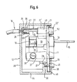
- Figur 6
- eine zu Figur 5 analoge Ansicht bei in die Schalter-Betätigungsposition geschwenktem Bart des Profil-Halbzylinderschlosses, wobei sich der Gewindezapfen noch in seiner Normallage befindet und
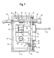
- Figur 7
- eine zu Figur 6 analoge Ansicht, wobei jedoch der Gewindezapfen aus der Frontplatte in die Notentriegelungsposition herausgedreht ist.
- Figure 1
- a front view of a cable pull key switch according to the invention with the trim and sealing plate removed,
- Figure 2
- 2 shows a front view of the housing of a cable-operated key switch according to the invention with the front plate removed and the switch arrangement removed,
- Figure 3
- 3 shows a corresponding front view as in FIG. 2 with the switch arrangement used and a half-byte lock shown in broken lines,
- Figure 4
- 3 shows a rear view of the front panel with the switch arrangement provided thereon,
- Figure 5
- 2 shows a partially sectioned side view of a key switch according to the invention with the key partially inserted in the key withdrawal or insertion position of the locking cylinder and with the threaded pin in the normal position,
- Figure 6
- a view analogous to FIG. 5 with the beard of the profile half-cylinder lock pivoted into the switch actuation position, the threaded pin still being in its normal position and
- Figure 7
- a view similar to Figure 6, but with the threaded pin is unscrewed from the front panel in the emergency release position.
Nach der Zeichnung weist ein erfindungsgemäßer Seilzug-Schlüsselschalter
eine quadratische Frontplatte 11 auf, die in ein quaderförmiges
Gehäuse 12 eingesetzt ist, von dessen Unterwand 44 sich
nach Fig. 5 im Abstand vom Vorderrand 46 ein laschenförmiger Befestigungsvorsprung
30 nach oben erstreckt, in dem sich eine Gewindebohrung
31 befindet, die mit einer Befestigungsbohrung 32 in der Frontplatte
11 axial ausgerichtet ist. Wie man Figur 5 entnehmen kann, ist die Frontplatte
11 in fertig montiertem Zustand durch eine Dichtplatte 35 sowie
eine anschließende Verkleidungsplatte 36 abgedeckt, welche mit den Öffnungen
in der Frontplatte 11 korrespondierende Öffnungen aufweisen.
Die Verkleidungsplatte 36, die Dichtplatte 35 und die Frontplatte 11 sind
dadurch am Gehäuse 12 befestigt, daß durch die mit der Befestigungsbohrung
32 korrespondierenden Bohrungen 33 der Dichtplatte 35 und 34
der Verkleidungsplatte 36 ein Bolzen 45 durch die Befestigungsbohrung
36 hindurch in die Gewindebohrung 31 eingeschraubt ist.According to the drawing, a cable pull key switch according to the invention
a
Von der Hinterseite der Frontplatte 11 springt eine Befestigungslasche 37
in das Innere des Gehäuses 12 vor, an der mittels eines Bolzens 38 ein
Profil-Halbzylinderschloß 13 befestigt ist. Die Vorderseite des Schlosses
durchgreift eine zu ihm komplementäre Öffnung 14 in der Frontplatte 11
(Figur 1).A
In den Schließzylinder 19 des Profil-Halbzylinderschlosses 12 ist ein Sicherheitsschlüssel
15 (Figur 5) in üblicher Weise einsteckbar, und zwar
lediglich in der in Figur 1 und 5 dargestellten Schlüssel-Abzugs- bzw.
-Einsteckposition. In dieser befindet sich der Bart 16 (Figur 5) des Schlosses
in einer senkrecht nach oben weisenden Position.In the
Aus dieser Position kann der Schließzylinder 19 und damit der Bart 16 in
beiden Richtungen verdreht werden, um nach Fig. 3, 4 mit Schaltern 17,
17' in Eingriff zu kommen, die an einem Kunststoffeinsatz 42 vorgesehen
sind, der sich zwischen der Frontplatte 11 und der Rückwand 39 des Gehäuses
12 befindet.From this position, the
Erfindungsgemäß sind oberhalb der Öffnung 14 für das Profil-Halbzylinderschloß
13 eine Bohrung 21 in der Frontplatte 11 und entsprechende
Bohrungen in den daraufliegenden Dicht- bzw. Verkleidungsplatten
35, 36 vorgesehen. Unmittelbar hinter dieser Bohrung 21 ist an die
Frontplatte 11 ein Verstärkungsansatz 43 angeformt (Figuren 4, 5), welcher
eine mit der Bohrung 21 ausgerichteten Kanal 21' aufweist. Die Bohrung
21 und der Kanal 21' sind mit einem durchgehenden Innengewinde
versehen, in welchem ein Gewindezapfen 22 angeordnet ist, der mit einem
Betätigungskopf 22' (Figur 5) von der Frontplatte 11 bzw. der Verkleidungsplatte
36 nach vorn vorsteht und eine Inbusbohrung 40 aufweist
(Figur 1), in die ein Inbusschlüssel 41 (Figur 3) einsteckbar ist. Der Betätigungskopf
22' ist außerdem mit einem Querschlitz 49 versehen, in den
ein Werkzeug oder eine Münze zwecks Betätigung eingesteckt werden
kann.According to the invention are above the
Weiter weist der Kopf eine Markierung 50 in Form eines roten Punktes
auf, die mit einer Gegenmarkierung 51 an der Verkleidungsplatte 36 zusammenwirkt.
Die Normallage ist erst erreicht, wenn nach dem Einschrauben
die Markierung 50 mit der Gegenmarkierung 51 ausgerichtet
ist.The head also has a marking 50 in the form of a red dot
on, which cooperates with a
Der Gewindezapfen 22 steht nach hinten aus dem Verstärkungsansatz 43
vor und reicht im voll eingeschraubten Zustand (Figur 5) bis annähernd
zur Rückwand 39 des Gehäuses 12. The threaded
Erfindungsgemäß weist der Gewindezapfen 22 in einem in der in Figur 5
gezeigten Normallage aus dem Verstärkungsansatz 43 vorstehenden Bereich
einseitig eine Vertiefung 24 auf, die radial von außen bis etwa zur
Mittelachse des Gewindezapfens 22 reicht.According to the invention, the threaded
Der Gewindezapfen 22 ist zumindest in dem Bereich von der Vertiefung 24
bis zum nahe der Rückwand 39 gelegenen Ende hohl (47) ausgebildet, um
Platz für eine Anschlagverdickung 20 zu schaffen, die am Ende der durch
eine Bohrung in der Rückwand 39 des Gehäuses 12 geführten Seele 18'
eines Bowdenzuges 18 befestigt ist. Das hintere Ende des Gewindezapfens
22 verengt sich jedoch gegenüber dem Hohlraum 47 wieder zu einer
schmalen Öffnung 48, die lediglich für den Durchlaß der Seele 18' des
Bowdenzuges 18 ausreicht. Durch die Vertiefung 24 kann die Seele 18'
mit der Anschlagverdickung 20 bequem in den Hohlraum 47 eingebracht
werden. Der Bowdenzug 18 stellt eine Notbetätigungsvorrichtung für einen
nicht dargestellten Tor-Entriegelungsmechnismus dar.The threaded
Die Dimensionierung des Gewindezapfens 22 sowie seine Anordnung relativ
zum Profil-Halbzylinderschloß 13 sind so, daß in der in Figur 5 dargestellten
Neutralposition des Schlosses der Bart 16 weitgehend formschlüssig
in die Vertiefung 24 eintritt, wobei insbesondere die obere Endfläche
25 des Bartes 16 so nahe am flachen Boden der Vertiefung 24 liegt, daß
eine Verdrehung des Gewindezapfens 22 nicht möglich ist.The dimensioning of the threaded
Zwischen dem Betätigungskopf 22' und dem Haltezapfen 22 weist letzterer
eine Einschnürung 52 auf, welche als Soll-Bruchstelle wirkt, derart, daß
bei dem Versuch, den Haltezapfen 22 mit Gewalt aus seiner Normallage
herauszudrehen, der Betätigungskopf 22' abbricht.The latter has between the actuating head 22 'and the holding pin 22
a
Der Bowdenzug 18 ist in nicht dargestellter Weise mit einer Not-Entriegelung
für das mittels des Schlüsselschalters betätigte Tor verbunden.
Eine derartige Notentriegelung arbeitet grundsätzlich in folgender
Weise.The
Normalerweise ist zwischen dem Antriebsmotor und dem Getriebe für die
Torbetätigung eine federbeaufschlagte Kupplung vorgesehen, die mittels
des Bowdenzuges 18 bei Herausschrauben des Gewindezapfens 22 ausgerückt
werden kann. Dadurch entfällt der bei versuchter Handöffnung vom
Motor aufgebrachte Widerstand, und das Tor kann nunmehr von Hand
geöffnet und geschlossen werden.Usually between the drive motor and the gearbox for the
Door actuation provided a spring-loaded clutch, which means
the
Es wäre auch denkbar, die am hinteren Ende der Vertiefung 24 vorhandene
Anschlagfläche 23 am Haltezapfen 22 (Fig. 5) für eine Sperrung gegen
Herausbewegen auszunutzen, und zwar insbesondere dann, wenn statt
der dargestellten Gewindeausführung ein in anderer Weise aus der Frontplatte
11 herausbewegbarer Haltezapfen 22 verwendet werden würde.It would also be conceivable to have the one at the rear end of the
Die Funktion des bisher beschriebenen Schlüsselschalters ist wie folgt:The function of the key switch described so far is as follows:
In der in Figur 5 dargestellten Neutralposition ist der Gewindezapfen 22
gegen Herausschrauben aus der Frontplatte 11 dadurch gesichert, daß
der Bart 16 weitgehend formschlüssig in die Vertiefung 24 eingreift. The threaded
Soll jetzt eine Notentriegelung des von dem Schlüsselschalter betätigten
Tores erfolgen, wird der Schlüssel 15 in den Schließzylinder 19 eingesteckt
und dieser in der einen oder anderen Richtung so weit verdreht, bis
der Bart 16 aus der Vertiefung 24 im Gewindezapfen 22 freikommt. Nunmehr
kann der Gewindezapfen 22 mittels eines in die Inbusöffnung 40
eingesteckten Werkzeuges 41 aus der Frontplatte herausgeschraubt werden,
wodurch die Seele 18' des Bowdenzuges 18 mitgenommen wird, um
den Notentriegelungsmechnismus zu betätigen. Das vom erfindungsgemäßen
Schlüsselschalter betätigte Tor kann nunmehr von Hand geöffnet
werden.Now an emergency release of the operated by the key switch
Tores take place, the key 15 is inserted into the
Ein erneutes Abziehen des Schlüssels 15 ist erst dann möglich, wenn der
Gewindezapfen 22 mittels des Werkzeuges 41 wieder in die aus Figur 5
ersichtliche Position eingeschraubt und die Markierung 50 mit der Gegenmarkierung
51 in Ausrichtung gebracht worden ist.A renewed removal of the key 15 is only possible when the
Threaded
In Weiterbildung der Erfindung ist oberhalb des Endbereiches des Gewindezapfens
22 am Gehäuse ein Vorsprung 29 vorgesehen, der unten eine
Anschlagfläche 26 aufweist, die in geringem Abstand dem gehäuseseitigen
Endbereich des Gewindezapfens 22 gegenüberliegt. An der Unterseite der
Befestigungslasche 37 befindet sich ein nach unten vorstehender Anschlag
27, der eine Anschlagfläche 28 an der Hinterseite des Befestigungsvorsprunges
30 hintergreift. Die Anordnung der Anschlagfläche 26
sowie des Anschlages 27 und der Gegenfläche 28 sind derart, daß nach
Herausschrauben des Bolzens 45 aus der Gewindebohrung 31 des Befestigungsvorsprunges
30 eine Herausnahme der Frontplatte 11 nach vorn
nicht möglich ist, weil die Frontplatte 11 aus der Position nach Figur 5
nur so weit gekippt werden kann, daß der Endbereich des Gewindezapfens
22 an die Anschlagfläche 26 stößt, was noch nicht dazu ausreicht, den
Anschlag 27 von der Gegenfläche 28 zu lösen. Erst wenn jetzt nach Einstecken
des Schlüssels und Herausschwenken des Bartes 16 aus der Vertiefung
24 der Gewindezapfen 22 mittels des Werkzeuges 41 so weit aus
der Frontplatte 11 herausgedreht wird, daß der Endbereich des Gewindezapfens
22 vollständig von der Gegenfläche 26 des Vorsprunges 29 freikommt
(Figur 7), kann die Frontplatte um eine im unteren Bereich des
Gehäuses liegende Querachse so weit verschwenkt werden, daß sich der
Endbereich des Gewindezapfens 22 in Richtung des Pfeiles f in Figur 7
bewegen kann, wodurch nach dem Heraustreten des oberen Randes der
Frontplatte 11 aus der Vorderöffnung des Gehäuses 12 der Anschlag 27
von der Gegenfläche 28 freikommt und nunmehr die Frontplatte 11 mit
den an ihr angeordneten Teilen aus dem Gehäuse 22 entfernt werden
kann.In a development of the invention is above the end region of the threaded
Statt oder zusätzlich zu dem Vorsprung 29 könnte auch um die Durchführungsbohrung
für die Seele 18' herum in der Rückwand 39 innen eine
Vertiefung für den Gewindezapfen 22 vorgesehen sein, deren Oberwand
der Anschlagfläche 26 entsprechen würde.Instead of or in addition to the
Die erfindungsgemäße Not-Betätigungsvorrichtung erhält auf diese Weise eine zusätzliche Funktion als Bauelement zur Verhinderung einer Demontage des Schlüsselschalters ohne vorher eingesteckten Schlüssel. The emergency actuation device according to the invention is obtained in this way an additional function as a component to prevent disassembly the key switch without a key inserted beforehand.
- 1111
- Frontplattefront panel
- 1212
- Gehäusecasing
- 1313
- Profil-HalbzylinderschloßProfile half cylinder lock
- 1414
- Öffnungopening
- 1515
- Schlüsselkey
- 1616
- Bartbeard
- 1717
- Schalterswitch
- 17'17 '
- Schalterswitch
- 1818
- Not-Betätigungsvorrichtung (Bowdenzug)Emergency actuation device (Bowden cable)
- 18'18 '
- Seelesoul
- 1919
- Schließzylinderlock cylinder
- 2020
- Anschlagverdickungstop thickening
- 2121
- Bohrungdrilling
- 21'21 '
- Kanalchannel
- 2222
- Haltezapfen (Gewindezapfen)Retaining pin (threaded pin)
- 22'22 '
- Betätigungskopfactuating head
- 2323
- Anschlagattack
- 2424
- Vertiefungdeepening
- 2525
- Endflächeend face
- 2626
- Anschlagflächestop surface
- 2727
- Anschlagattack
- 2828
- Gegenflächecounter surface
- 2929
- Vorsprunghead Start
- 3030
- Befestigungsvorsprungfixing projection
- 3131
- Gewindebohrung threaded hole
- 3232
- Befestigungsbohrungmounting hole
- 3333
- Bohrungdrilling
- 3434
- Bohrungdrilling
- 3535
- Dichtplattesealing plate
- 3636
- VerkleidungsplatteFacing tile
- 3737
- Befestigungslaschemounting tab
- 3838
- Bolzenbolt
- 3939
- Rückwandrear wall
- 4040
- InbusöffnungInbusöffnung
- 4141
- InbusschlüsselAllen key
- 4242
- KunststoffeinsatzPlastic insert
- 4343
- Verstärkungsansatzreinforcement approach
- 4444
- Unterwandunder wall
- 4545
- Bolzenbolt
- 4646
- Vorderwandfront wall
- 4747
- Hohlraumcavity
- 4848
- Öffnungopening
- 4949
- Schlitzslot
- 5050
- Markierungmark
- 5151
- GegenmarkierungPosition indicator
- 5252
- Soll-Bruchstelle (Einschnürung)Target breaking point (constriction)
- ff
- Pfeilarrow
Claims (23)
dadurch gekennzeichnet, daß die Not-Betätigungsvorrichtung (18) einen in einer Bohrung (21) der Frontplatte (11) vorzugsweise senkrecht zu dieser beweglich angeordneten Haltezapfen (22) aufweist, der eine Normallage hat, in der die Not-Betätigungsvorrichtung (18) unwirksam ist und der Schließzylinder (19) ungehindert vom Haltezapfen (22) in seine Schlüssel-Abzugs- bzw. -Einsteckposition bringbar ist, sowie zur Bewegung der Not-Betätigungsvorrichtung in die Entriegelungsstellung dann und nur dann aus der Normallage herausbewegbar ist, wenn der Schließzylinder (19) sich außerhalb der Schlüssel-Abzugs- bzw, Einsteckposition befindet.Cable-operated key switch for electric drives of movable devices, in particular for electric door or gate drives, with an unlocking mechanism which can be actuated in the event of failure of the electric drive for the purpose of manual operation of the device, with a removable front plate (11) in an opening (14) ) a box-shaped housing (12) attached cylinder lock, in particular profile half-cylinder lock (13), with a lock cylinder (19), into which a key (15) can be inserted from the outside, which key inside the housing (12) by means of the key ( 15) has a pivotable switch bit (16) which, when the key (15) inserted into the locking cylinder (19) is rotated, acts on at least one electrical switch (17, 17 ') in one direction or the other from its withdrawal or insertion position, whereby in the housing (12) opens an elongated mechanical emergency actuation device (18), such as a Bowden cable, which with d an unlocking mechanism is connected and can be moved mechanically, preferably by means of a tool (41), from one side of the housing (12), preferably from the front (19), provided that the locking cylinder (19) is in a predetermined rotational position outside the key Deduction or insertion position,
characterized in that the emergency actuating device (18) has a holding pin (22), which is preferably movably arranged in a bore (21) of the front plate (11) and has a normal position in which the emergency actuating device (18) is ineffective and the locking cylinder (19) can be moved freely from the holding pin (22) into its key withdrawal or insertion position, and for moving the emergency actuating device into the unlocking position, and can only be moved out of the normal position when the locking cylinder ( 19) is outside of the key withdrawal or insertion position.
dadurch gekennzeichnet, daß an der hinteren Fläche der Frontplatte (11) im Bereich der Bohrung (21) ein Verstärkungsansatz (43) mit einem die Bohrung (21) fortsetzenden Kanal (21') vorgesehen ist.Key switch according to claim 1,
characterized in that on the rear surface of the front plate (11) in the region of the bore (21) there is a reinforcement projection (43) with a channel (21 ') continuing the bore (21).
dadurch gekennzeichnet, daß der Haltezapfen (22) einen Anschlag (23) aufweist, der bei in der Normallage befindlichem Haltezapfen (22) und in der Schlüssel-Abzugs- bzw. -Einsteckposition befindlichem Schließzylinder (19) axial hinter dem Bart (16) liegt, derart, daß eine Herausbewegung des Haltezapfens (22) aus der Normallage unterbunden ist, und daß der Anschlag (23) nach Verdrehen des Schließzylinders (19) aus der Schlüssel-Abzugs- bzw. -Einsteckposition vom Bart (16) freikommt, derart, daß der Haltezapfen (22) nunmehr in die Entriegelungsstellung verschoben werden kann. Key switch according to claim 2,
characterized in that the holding pin (22) has a stop (23) which lies axially behind the beard (16) when the holding pin (22) is in the normal position and the locking cylinder (19) is in the key removal or insertion position , in such a way that the holding pin (22) is prevented from moving out of the normal position, and that the stop (23) is released from the beard (16) after turning the locking cylinder (19) from the key removal or insertion position, such that that the holding pin (22) can now be moved into the unlocked position.
dadurch gekennzeichnet, daß die Bohrung in der Frontplatte (11) und/oder der anschließende Kanal in dem Verstärkungsansatz (43) eine Gewindebohrung (21) bzw. einen Gewindekanal (21') und der Haltezapfen ein in diese Gewindebohrung (21) eingeschraubter Gewindezapfen (22) ist.Key switch according to one of the preceding claims,
characterized in that the bore in the front plate (11) and / or the adjoining channel in the reinforcement projection (43) has a threaded bore (21) or a threaded channel (21 ') and the retaining pin has a threaded pin (17) screwed into this threaded bore (21) 22) is.
dadurch gekennzeichnet, daß sich am Umfang des Gewindezapfens (22) eine Vertiefung (24) befindet, die komplementär zum radial äußeren Endbereich des Bartes (16) ausgebildet ist, derart, daß der Bart (16) bei in der Normallage befindlichem Gewindezapfen (22) und in der Schlüssel-Abzugs- bzw. -Einsteckposition des Schließzylinders (19) zumindest im wesentlichen formschlüssig in die Vertiefung (24) eingreift, derart, daß dann eine axiale Verschiebung des Gewindezapfens (22) zwecks Notbetätigung nicht möglich ist.Key switch according to claim 4,
characterized in that on the circumference of the threaded pin (22) there is a recess (24) which is complementary to the radially outer end region of the beard (16), such that the beard (16) with the threaded pin (22) in the normal position and in the key withdrawal or insertion position of the locking cylinder (19) engages at least essentially in a form-fitting manner in the recess (24) such that an axial displacement of the threaded pin (22) for emergency actuation is then not possible.
dadurch gekennzeichnet, daß die Vertiefung (24) nur einseitig vorgesehen ist und die radiale Endfläche (25) der Schaltzunge (16) in der Normallage des Gewindezapfens (22) und der Schlüssel-Abzugs- bzw. -Einsteckposition des Schließzylinders (19) mit dem Boden der Vertiefung (24) derart zusammenarbeitet, daß eine Verdrehung des Gewindezapfens (22) zur Überführung des Gewindezapfens (22) von der Normallage in die Entriegelungsstellung verunmöglicht ist. Key switch according to claim 5,
characterized in that the recess (24) is provided only on one side and the radial end face (25) of the switching tongue (16) in the normal position of the threaded pin (22) and the key withdrawal or insertion position of the locking cylinder (19) with the Bottom of the recess (24) cooperates in such a way that rotation of the threaded pin (22) to transfer the threaded pin (22) from the normal position into the unlocked position is impossible.
dadurch gekennzeichnet, daß der von der Frontplatte (11) abgewandte Endbereich des Haltezapfens (22) in der Normallage vorzugsweise oben einer Anschlagfläche (26) am Gehäuse (12) gegenüberliegt und auf der bezüglich des Schließzylinders (19) vom Haltezapfen (22) abgewandten Seite der Frontplatte (11) ein Anschlag (27) vorgesehen ist, der derart hinter eine Gegenfläche (28) des Gehäuses (12) greift, daß bei vom Gehäuse (12) gelöster Frontplatte (11) die Frontplatte (11) auch dann nicht aus dem Gehäuse (12) herausgenommen werden kann, wenn der Schließzylinder (19) aus der Schlüssel-Abzugs- bzw. Einsteckposition herausgedreht worden ist, daß jedoch der Haltezapfen (22) bei aus der Abzugs- bzw. Einsteckposition herausgeschwenktem Schlüssel (15) unter Beaufschlagung der Not-Betätigungsvorrichtung so weit aus der Ruhelage nach vorn aus der Frontplatte (11) herausbewegbar ist, daß der Endbereich der Haltezapfen (22) von der Anschlagfläche (26) am Gehäuse (12) freikommt und dadurch die Frontplatte (11) im wesentlichen um eine Querachse so weit schwenkbar ist, daß der Anschlag (27) von der Gegenfläche (28) freikommt.Key switch according to one of the preceding claims,
characterized in that the end region of the holding pin (22) facing away from the front plate (11) in the normal position is preferably opposite a stop surface (26) on the housing (12) and on the side facing away from the holding pin (22) with respect to the locking cylinder (19) the front plate (11) is provided with a stop (27) which engages behind a counter surface (28) of the housing (12) in such a way that when the front plate (11) is detached from the housing (12) the front plate (11) does not come out of the Housing (12) can be removed when the lock cylinder (19) has been unscrewed from the key withdrawal or insertion position, but that the retaining pin (22) when the key (15) is pivoted out of the withdrawal or insertion position while the Emergency actuating device can be moved out of the front plate (11) so far out of the idle position that the end region of the holding pins (22) is released from the stop surface (26) on the housing (12) and thereby the front plate (11) can be pivoted substantially so far about a transverse axis that the stop (27) is released from the counter surface (28).
dadurch gekennzeichnet, daß die Anschlagfläche (26) an einem vorzugsweise von oben in das Gehäuseinnere vorstehenden Vorsprung (29) vorgesehen ist, dessen Ausdehnung in Richtung der Frontplatte (11) so begrenzt ist, daß der Gewindezapfen im mehr oder weniger aus der Normallage herausgeschraubten Zustand von der Anschlagfläche (26) freikommen kann.Key switch according to claim 7,
characterized in that the abutment surface (26) is provided on a projection (29) which preferably projects into the interior of the housing from above, the extent of which in the direction of the front plate (11) is so limited that the threaded pin is more or less unscrewed from the normal position can come free from the stop surface (26).
dadurch gekennzeichnet, daß die Gegenfläche (28) des Gehäuses (12) an einem vorzugsweise von der Unterwand (44) des Gehäuses (12) vorstehenden Befestigungsvorsprung (30) vorgesehen ist, der eine Gewindebohrung (31) zum Festschrauben der Frontplatte mittels nur eines einzigen Bolzens (45) aufweist.Key switch according to claim 7 or 8,
characterized in that the counter surface (28) of the housing (12) is provided on a fastening projection (30), preferably projecting from the lower wall (44) of the housing (12), which has a threaded bore (31) for screwing the front panel tight by means of only one Has bolt (45).
dadurch gekennzeichnet, daß der Gewindebohrung (31) im Befestigungsvorsprung (30) gegenüberliegend eine Befestigungsbohrung (33) in der Frontplatte (11) vorgesehen ist.Key switch according to claim 9,
characterized in that the threaded hole (31) in the fastening projection (30) opposite a fastening hole (33) is provided in the front plate (11).
dadurch gekennzeichnet, daß mit der Befestigungsbohrung (32) ausgerichtete Bohrungen (33, 34) auch in die Frontplatte (11) abdeckenden Dicht- bzw. Verkleidungsplatten (35, 36) vorgesehen sind.Key switch according to claim 10,
characterized in that bores (33, 34) aligned with the fastening bore (32) are also provided in sealing or cladding panels (35, 36) covering the front panel (11).
dadurch gekennzeichnet, daß der Anschlag (27) vorzugsweise unten an einer von der Frontplatte (11) nach hinten vorstehenden Befestigungslasche (37) vorgesehen ist, an der mittels eines Bolzens (38) das Zylinderschloß (13) befestigt ist.Key switch according to one of claims 7 to 11,
characterized in that the stop (27) is preferably provided at the bottom on a fastening tab (37) projecting rearward from the front plate (11), to which the cylinder lock (13) is fastened by means of a bolt (38).
dadurch gekennzeichnet, daß der Haltezapfen (22) in der Normallage zumindest bis annähernd zur Rückwand (39) des Gehäuses (12) reicht und/oder daß der Haltezapfen (22) in der Normallage in eine Bohrung der Rückwand (39) des Gehäuses (12) eingreift.Key switch according to one of the preceding claims,
characterized in that the retaining pin (22) in the normal position extends at least approximately to the rear wall (39) of the housing (12) and / or in that the retaining pin (22) in the normal position in a bore in the rear wall (39) of the housing (12 ) intervenes.
dadurch gekennzeichnet, daß der Haltezapfen (22) und der Anschlag (27) bezüglich der Achse des Schließzylinders (19) diametral gegenüberliegen.Key switch according to one of claims 7 to 13,
characterized in that the retaining pin (22) and the stop (27) are diametrically opposite with respect to the axis of the locking cylinder (19).
dadurch gekennzeichnet, daß die Achse des Haltezapfens (22) parallel zur Achse des Schließzylinders (19) verläuft.Key switch according to one of the preceding claims,
characterized in that the axis of the retaining pin (22) runs parallel to the axis of the locking cylinder (19).
dadurch gekennzeichnet, daß der Haltezapfen (22) in geringem Abstand oberhalb des Zylinderschlosses (18) angeordnet ist.Key switch according to one of the preceding claims,
characterized in that the holding pin (22) is arranged at a short distance above the cylinder lock (18).
dadurch gekennzeichnet, daß die Befestigungsbohrung (32) für die Frontplatte (11) und gegebenenfalls die Dichtplatte (35) bzw. die Verkleidungsplatte (36) unterhalb des Zylinderschlosses (13) vorgesehen ist.Key switch according to one of the preceding claims,
characterized in that the mounting hole (32) for the front plate (11) and optionally the sealing plate (35) or the cladding plate (36) is provided below the cylinder lock (13).
dadurch gekennzeichnet, daß der Haltezapfen (22) auf seiner von der Frontplatte (11) her zugänglichen Seite eine Werkzeugangriffsausbildung, insbesondere eine Inbus-Bohrung (40) und/oder einen Schlitz (49) für das Einbringen eines Schraubendrehers oder eines Geldstückes aufweist, in die ein geeignetes Werkzeug, insbesondere ein Inbusschlüssel (41) einsteckbar ist.Key switch according to one of the preceding claims,
characterized in that the holding pin (22) has on its side accessible from the front plate (11) a tool engagement formation, in particular an Allen hole (40) and / or a slot (49) for the insertion of a screwdriver or a coin, in a suitable tool, in particular an Allen key (41), can be inserted.
dadurch gekennzeichnet, daß zwei Schalter (17, 17') symmetrisch zur Schließzylinderachse an einem Kunststoffeinsatz (42) vorgesehen sind, der unabhängig von der Frontplatte (11) in das Gehäuse (12) derart einsetzbar ist, daß der Bart (16) beidseits der Schlüssel-Abzugs- bzw. -Einsteckposition des Schließzylinders (19) die Schalter (17, 17') betätigen kann.Key switch according to one of the preceding claims,
characterized in that two switches (17, 17 ') are provided symmetrically to the lock cylinder axis on a plastic insert (42) which can be inserted into the housing (12) independently of the front plate (11) in such a way that the beard (16) on both sides of the Key withdrawal or insertion position of the lock cylinder (19) can operate the switches (17, 17 ').
dadurch gekennzeichnet, daß das Gehäuse (12) quaderförmig ausgebildet ist und die Frontplatte eine rechteckige, insbesondere quadratische Form hat.Key switch according to one of the preceding claims,
characterized in that the housing (12) is cuboid and the front plate has a rectangular, in particular square, shape.
dadurch gekennzeichnet,
der Haltezapfen (22) zumindest in dem auch die Vertiefung (24) aufweisenden Endbereich hohl ausgebildet ist und dort die Verbindungsmittel (20) für die Not-Betätigungsvorrichtung (18) aufnimmt.Key switch according to one of the preceding claims,
characterized by
the holding pin (22) is hollow at least in the end region also having the recess (24) and there receives the connecting means (20) for the emergency actuating device (18).
dadurch gekennzeichnet, daß der Kopf des Haltezapfens (22) eine Markierung (50), z.B. in Form eines roten Punktes, aufweist, die mit einer an der Front- bzw. Verkleidungsplatte vorgesehenen Gegenmarkierung (51) derart zusammenwirkt, daß nach dem Einschrauben des Haltezapfens (22) im wesentlichen in die Normallage durch Ausrichtung von Markierung (50) und Gegenmarkierung (51) die exakte Normallage herstellbar ist.Key switch according to one of the preceding claims,
characterized in that the head of the holding pin (22) has a marking (50), for example in the form of a red dot, which interacts with a counter marking (51) provided on the front or cladding panel in such a way that after screwing in the holding pin (22) essentially in the normal position by aligning the marking (50) and countermarking (51) the exact normal position can be produced.
dadurch gekennzeichnet, daß zwischen dem Betätigungskopf (22') und dem eigentlichen Haltezapfen (22) eine Soll-Bruchstelle (52) vorgesehen ist.Key switch according to one of the preceding claims,
characterized in that a predetermined breaking point (52) is provided between the actuating head (22 ') and the actual holding pin (22).
Priority Applications (2)
| Application Number | Priority Date | Filing Date | Title |
|---|---|---|---|
| ES01112625T ES2222291T3 (en) | 2001-05-23 | 2001-05-23 | WRENCH SWITCH WITH CONTROL CABLE. |
| EP20010112625 EP1263010B1 (en) | 2001-05-23 | 2001-05-23 | Key switch with cable control |
Applications Claiming Priority (1)
| Application Number | Priority Date | Filing Date | Title |
|---|---|---|---|
| EP20010112625 EP1263010B1 (en) | 2001-05-23 | 2001-05-23 | Key switch with cable control |
Publications (2)
| Publication Number | Publication Date |
|---|---|
| EP1263010A1 true EP1263010A1 (en) | 2002-12-04 |
| EP1263010B1 EP1263010B1 (en) | 2004-08-18 |
Family
ID=8177530
Family Applications (1)
| Application Number | Title | Priority Date | Filing Date |
|---|---|---|---|
| EP20010112625 Expired - Lifetime EP1263010B1 (en) | 2001-05-23 | 2001-05-23 | Key switch with cable control |
Country Status (2)
| Country | Link |
|---|---|
| EP (1) | EP1263010B1 (en) |
| ES (1) | ES2222291T3 (en) |
Cited By (2)
| Publication number | Priority date | Publication date | Assignee | Title |
|---|---|---|---|---|
| EP2442337A1 (en) | 2010-10-15 | 2012-04-18 | Sewosy, Société Par Actions Simplifiée | Key contactor device |
| CN111415835A (en) * | 2019-01-08 | 2020-07-14 | C·鲍姆加特 | Key switch |
Families Citing this family (1)
| Publication number | Priority date | Publication date | Assignee | Title |
|---|---|---|---|---|
| EP3703022B1 (en) * | 2019-03-01 | 2024-05-29 | Diebold Nixdorf Systems GmbH | Assembly for secure closing of a topside module of a device for handling vouchers |
Citations (2)
| Publication number | Priority date | Publication date | Assignee | Title |
|---|---|---|---|---|
| US3766341A (en) * | 1973-02-20 | 1973-10-16 | Ramm Ind | Locking device |
| DE4407678A1 (en) * | 1994-03-08 | 1995-09-14 | Baumgart Ind Co Sa | Key switch |
-
2001
- 2001-05-23 ES ES01112625T patent/ES2222291T3/en not_active Expired - Lifetime
- 2001-05-23 EP EP20010112625 patent/EP1263010B1/en not_active Expired - Lifetime
Patent Citations (2)
| Publication number | Priority date | Publication date | Assignee | Title |
|---|---|---|---|---|
| US3766341A (en) * | 1973-02-20 | 1973-10-16 | Ramm Ind | Locking device |
| DE4407678A1 (en) * | 1994-03-08 | 1995-09-14 | Baumgart Ind Co Sa | Key switch |
Cited By (2)
| Publication number | Priority date | Publication date | Assignee | Title |
|---|---|---|---|---|
| EP2442337A1 (en) | 2010-10-15 | 2012-04-18 | Sewosy, Société Par Actions Simplifiée | Key contactor device |
| CN111415835A (en) * | 2019-01-08 | 2020-07-14 | C·鲍姆加特 | Key switch |
Also Published As
| Publication number | Publication date |
|---|---|
| EP1263010B1 (en) | 2004-08-18 |
| ES2222291T3 (en) | 2005-02-01 |
Similar Documents
| Publication | Publication Date | Title |
|---|---|---|
| EP1447500B1 (en) | Security blocking device | |
| DE102007035218A1 (en) | Electrically automated unlocking lock, especially for locker-like storage systems | |
| DE112007001826B4 (en) | lock mechanism | |
| EP0610542B1 (en) | Mortise lock especially for apartment doors, in particular a lock with sliding bars | |
| EP0324096A2 (en) | Locking cylinder, especially a cylinder for a mortise lock | |
| EP1885977B1 (en) | Safety lock for a door, a gate or the like | |
| DE19813166A1 (en) | Door lock arrangement, preferably espagnolette lock arrangement | |
| DE102015001960A1 (en) | Locking cylinder with two on the same axis spaced locking lugs | |
| EP0653533B1 (en) | Lockable actuating rod for pivoting and tilting windows | |
| EP1056915B1 (en) | Door lock | |
| EP0175211A1 (en) | Socket spanner actuated and arrested by a sash lock | |
| DE3806189A1 (en) | LOCKING DEVICE | |
| EP1724417B1 (en) | Lock element | |
| EP0779404A2 (en) | Security lock | |
| EP0635612B1 (en) | Doorlock device | |
| EP1263010B1 (en) | Key switch with cable control | |
| EP3366873B1 (en) | Window/door guard | |
| EP0779402B1 (en) | Safety lock | |
| EP1172506B1 (en) | Safety device against wrong operation of espagnolettes | |
| DE3342458C2 (en) | ||
| DE3432981A1 (en) | SIDE LOCK OF A LOCKING DEVICE FOR BURGLAR-RESISTANT DOORS | |
| DE10329560B4 (en) | Device for securing a closure part | |
| DE202005003529U1 (en) | Lock system especially for all glass door is fitted into a hand grip spaced from the door and with the axial position of the cylinder lock controlled by an alignment bracket | |
| EP3543436B1 (en) | Counter lock for a passive door | |
| EP1732095A2 (en) | Locking device for switch box |
Legal Events
| Date | Code | Title | Description |
|---|---|---|---|
| PUAI | Public reference made under article 153(3) epc to a published international application that has entered the european phase |
Free format text: ORIGINAL CODE: 0009012 |
|
| AK | Designated contracting states |
Kind code of ref document: A1 Designated state(s): AT BE CH CY DE DK ES FI FR GB GR IE IT LI LU MC NL PT SE TR |
|
| AX | Request for extension of the european patent |
Free format text: AL;LT;LV;MK;RO;SI |
|
| AKX | Designation fees paid | ||
| 17P | Request for examination filed |
Effective date: 20030729 |
|
| RBV | Designated contracting states (corrected) |
Designated state(s): ES FR IT |
|
| REG | Reference to a national code |
Ref country code: DE Ref legal event code: 8566 |
|
| GRAP | Despatch of communication of intention to grant a patent |
Free format text: ORIGINAL CODE: EPIDOSNIGR1 |
|
| GRAS | Grant fee paid |
Free format text: ORIGINAL CODE: EPIDOSNIGR3 |
|
| GRAA | (expected) grant |
Free format text: ORIGINAL CODE: 0009210 |
|
| AK | Designated contracting states |
Kind code of ref document: B1 Designated state(s): ES FR IT |
|
| REG | Reference to a national code |
Ref country code: IE Ref legal event code: FG4D Free format text: GERMAN |
|
| REG | Reference to a national code |
Ref country code: ES Ref legal event code: FG2A Ref document number: 2222291 Country of ref document: ES Kind code of ref document: T3 |
|
| REG | Reference to a national code |
Ref country code: IE Ref legal event code: FD4D |
|
| ET | Fr: translation filed | ||
| PLBE | No opposition filed within time limit |
Free format text: ORIGINAL CODE: 0009261 |
|
| STAA | Information on the status of an ep patent application or granted ep patent |
Free format text: STATUS: NO OPPOSITION FILED WITHIN TIME LIMIT |
|
| 26N | No opposition filed |
Effective date: 20050519 |
|
| PGFP | Annual fee paid to national office [announced via postgrant information from national office to epo] |
Ref country code: ES Payment date: 20100525 Year of fee payment: 10 |
|
| REG | Reference to a national code |
Ref country code: ES Ref legal event code: FD2A Effective date: 20130404 |
|
| PG25 | Lapsed in a contracting state [announced via postgrant information from national office to epo] |
Ref country code: ES Free format text: LAPSE BECAUSE OF NON-PAYMENT OF DUE FEES Effective date: 20110524 |
|
| PGFP | Annual fee paid to national office [announced via postgrant information from national office to epo] |
Ref country code: IT Payment date: 20140530 Year of fee payment: 14 |
|
| PGFP | Annual fee paid to national office [announced via postgrant information from national office to epo] |
Ref country code: FR Payment date: 20140530 Year of fee payment: 14 |
|
| PG25 | Lapsed in a contracting state [announced via postgrant information from national office to epo] |
Ref country code: IT Free format text: LAPSE BECAUSE OF NON-PAYMENT OF DUE FEES Effective date: 20150523 |
|
| REG | Reference to a national code |
Ref country code: FR Ref legal event code: ST Effective date: 20160129 |
|
| PG25 | Lapsed in a contracting state [announced via postgrant information from national office to epo] |
Ref country code: FR Free format text: LAPSE BECAUSE OF NON-PAYMENT OF DUE FEES Effective date: 20150601 |