EP1262767A2 - Humidity sensor - Google Patents
Humidity sensor Download PDFInfo
- Publication number
- EP1262767A2 EP1262767A2 EP02011947A EP02011947A EP1262767A2 EP 1262767 A2 EP1262767 A2 EP 1262767A2 EP 02011947 A EP02011947 A EP 02011947A EP 02011947 A EP02011947 A EP 02011947A EP 1262767 A2 EP1262767 A2 EP 1262767A2
- Authority
- EP
- European Patent Office
- Prior art keywords
- moisture
- sensitive layer
- humidity sensor
- detection electrodes
- sensor according
- Prior art date
- Legal status (The legal status is an assumption and is not a legal conclusion. Google has not performed a legal analysis and makes no representation as to the accuracy of the status listed.)
- Granted
Links
Images




Classifications
-
- G—PHYSICS
- G01—MEASURING; TESTING
- G01N—INVESTIGATING OR ANALYSING MATERIALS BY DETERMINING THEIR CHEMICAL OR PHYSICAL PROPERTIES
- G01N27/00—Investigating or analysing materials by the use of electric, electrochemical, or magnetic means
- G01N27/02—Investigating or analysing materials by the use of electric, electrochemical, or magnetic means by investigating impedance
- G01N27/04—Investigating or analysing materials by the use of electric, electrochemical, or magnetic means by investigating impedance by investigating resistance
- G01N27/12—Investigating or analysing materials by the use of electric, electrochemical, or magnetic means by investigating impedance by investigating resistance of a solid body in dependence upon absorption of a fluid; of a solid body in dependence upon reaction with a fluid, for detecting components in the fluid
- G01N27/121—Investigating or analysing materials by the use of electric, electrochemical, or magnetic means by investigating impedance by investigating resistance of a solid body in dependence upon absorption of a fluid; of a solid body in dependence upon reaction with a fluid, for detecting components in the fluid for determining moisture content, e.g. humidity, of the fluid
Definitions
- the present invention relates to a humidity sensor for measuring the moisture content of an atmosphere by means of change in an electrical resistance of a moisture-sensitive layer.
- the humidity sensor can be used, for example, for measuring the moisture content of air; the moisture content of exhaust gas in an exhaust pipe of an internal combustion engine of, for example, an automobile, ship, or airplane; or the moisture content of, for example, an atmosphere surrounding a fuel electrode or an air electrode or an atmosphere in a pipe of a fuel cell.
- employed humidity sensors include resistance-variable-type humidity sensors utilizing adsorption and desorption of water molecules; and capacitance-variable-type humidity sensors utilizing change in capacitance.
- Such humidity sensors are formed from a moisture sensitive material such as Al 2 O 3 , MgCr 2 O 4 -TiO 2 , TiO 2 -V 2 O 5 , or ZrCr 2 O 4 -LiZrVO 4 .
- Most of the humidity sensors measure a change in electric resistance.
- Humidity sensors formed from such moisture sensitive ceramic materials are typically fabricated by a method described in, for example, Japanese Patent Publication ( kokoku ) No. 1989-22965. Specifically, a lower electrode is formed on an insulating substrate; a moisture-sensitive layer is formed through pelleting or a like process in such a manner as to overlie the lower electrode; and an upper electrode is formed on the upper surface of the moisture-sensitive layer.
- a humidity sensor whose detection electrodes each assume a comblike shape is also known.
- Such conventional humidity sensors can be used in the ordinary atmosphere or the like without involvement of problems.
- the conventional humidity sensors involve problems, such as low-precision measurement and impaired response, in application to measurement in an atmosphere which exhibits significant temperature variation (e.g. -40 to 750 °C), very low oxygen concentration, and significant variations in, for example, gas flow velocity, gas flow rate, and gas pressure, as in an exhaust pipe of an automobile, or in application to measurement in an atmosphere which contains a considerable amount of reducing gas, such as an atmosphere surrounding a fuel electrode of a fuel cell.
- a humidity sensor In application to measurement in such an atmosphere, a humidity sensor must exhibit excellent thermal shock resistance in addition to sufficiently good response.
- a conventional humidity sensor including a moisture-sensitive layer formed through pelleting or a common thick-film-type humidity sensor fails to detect accurately and at highly good response a change in electrical resistance of the moisture-sensitive layer which is induced by the moisture content of an atmosphere to be measured, and fails to exhibit sufficient strength in relation to thermal shock resistance, etc.
- An object of the present invention is to provide a humidity sensor capable of exhibiting highly good response and excellent strength in relation to, for example, thermal shock resistance, and capable of maintaining stable moisture sensitivity over a long period of time, even in application to measurement in an atmosphere which exhibits significant temperature variation, very low oxygen concentration, and significant variations in, for example, gas flow velocity, gas flow rate, and gas pressure, as in an exhaust pipe of a vehicle.
- the humidity sensor When the moisture-sensitive layer of a humidity sensor assumes the form of a thin layer having a certain thickness, the humidity sensor can exhibit enhanced response, and thermal stress can be reduced.
- the detection electrodes of the humidity sensor are formed of a porous material that is formed from a noble metal, such as Pt or Au which exhibits excellent heat resistance and corrosion resistance and has an average pore size greater than that of the moisture-sensitive layer, strong adhesion can be attained among an insulating substrate, the detection electrodes, and the moisture-sensitive layer while excellent response, for example, is maintained intact. Even in application to measurement in a specific atmosphere as in an exhaust pipe of a vehicle, such a humidity sensor can exhibit high accuracy, highly good response, and sufficient strength in relation to, for example, thermal shock resistance, and can maintain excellent humidity detection performance over a long period of time.
- the present invention has been accomplished on the basis of this finding.
- a humidity sensor of the present invention contains an insulating substrate, a detection electrodes, and a moisture-sensitive layer, and is characterized in that the moisture-sensitive layer is formed of a porous material and has a thickness not greater than 200 ⁇ m.
- the insulating substrate may be formed from a ceramic material, a resin, or a like material. Of these materials, a ceramic material, which exhibits most excellent heat resistance among these materials, is preferred. Examples of such a ceramic material include Al 2 O 3 and ZrO 2 . Of these ceramic materials, alumina, which exhibits excellent insulating property and mechanical strength and is advantageous in terms of cost, is more preferred. No particular limitations are imposed on the thickness and planar dimensions of the insulating substrate, but the substrate can be formed into a rectangular platy body having a thickness of 0.3 to 2.0 mm, a width of 3 to 8 mm, and a length of 10 to 50 mm.
- the aforementioned “detection electrodes” is formed from an electrically conductive material, and preferably contains a predominant amount (preferably, 50 to 99 %) of at least one noble metal selected from Au, Ag, Ru, Rh, Pd, Os, Ir, and Pt. Of these noble metals, Pt or Au is more preferred. Particularly, Pt is the most preferred, since Pt is not easily oxidized at high temperature, is not diffused in the moisture-sensitive layer, and has a sufficiently high melting point. Therefore, when the detection electrodes are formed from Pt, the humidity sensor exhibits further enhanced durability.
- the detection electrodes may be formed from an alloy containing two or more of above-described noble metals.
- a combination of Pt and Rh is useful, since evaporation of Pt at high temperature is suppressed.
- the electrodes formed from a noble metal may contain other components, so long as such "other components" do not greatly affect the properties of the electrodes.
- the term "predominant” or “predominantly” used in relation to noble metal content means, for example, that 100 parts by mass (weight) of detection electrodes contains a noble metal in an amount of not less than 75 parts by mass, preferably not less than 85 parts by mass.
- each of the detection electrodes predominantly contains a noble metal and is formed of a porous material.
- a gas to be measured can easily and uniformly diffuse in the moisture-sensitive layer and the detection electrodes, whereby response of the humidity sensor can be enhanced.
- diffusion of a gas to be measured is not limited within the detection electrodes, whereby response of the humidity sensor can be further enhanced.
- noble metal grains contained in the detection electrodes are rendered greater in average grain size than grains of a moisture sensitive material used for forming the moisture-sensitive layer.
- the detection electrodes can assume the form of a porous material which has an average pore size greater than that of the moisture-sensitive layer, whereby response of the moisture sensor can be enhanced as in the case where thin detection electrodes are employed.
- the average grain size of moisture sensitive material grains, the average grain size of noble metal grains, the average pore size of the moisture-sensitive layer, and the average pore size of the detection electrodes can be calculated from grain sizes and pore sizes obtained through electron micrography on a section of the moisture-sensitive layer and a section of the detection electrode.
- the diameter of pores in the upper electrode and the lower electrode each preferably fall within the range of from 0.5 ⁇ m to 20 ⁇ m.
- the diameter of pores in the moisture-sensitive layer preferably fall within the range of from 0.05 ⁇ m to 1 ⁇ m.
- the upper electrode and the lower electrode each contains a particulate ceramic such as particulate alumina and particulate zirconia incorporated therein in an amount of from 1 to 20% by weight.
- the reason for the restriction of the content of particulate ceramic to not smaller than 1% by weight is to exert a sufficient effect of improving the moisture permeability of the various electrodes.
- the reason for the restriction of the content of particulate ceramic to not greater than 20% by weight is to assure the prevention of malconduction of the various electrodes.
- Diffusion of a gas to be measured in the detection electrodes is also influenced by a material used for forming the electrodes.
- a material used for .forming the electrodes may contain a glass component and a sintering aid which contains an alkaline earth metal element.
- Such components are effective for facilitating firing at low temperature and for stabilizing the electrodes, but hinder diffusion of a gas to be measured. Therefore, preferably, the detection electrodes predominantly contains a noble metal not containing such components.
- a sintering aid to be used is preferably a compound of excellent thermal stability, such as alumina or zirconia, thereby enhancing adhesion between the detection electrodes and the insulating substrate or the moisture-sensitive layer.
- the planar shape of the detection electrodes is not particularly limited, but may be circular, elliptical, or, as shown in FIG. 1a, rectangular. Alternatively, the detection electrodes may assume a comblike form as shown in FIGS. 2a to 2c. Since portions of the detection electrodes which are not in contact with the moisture-sensitive layer do not function as the detection electrodes, the moisture-sensitive layer is preferably in contact with the entire surfaces of the detection electrodes.
- a pair of comblike electrodes, or the lower electrode formed on the lower surface of the moisture-sensitive layer and the upper electrode formed on the upper surface of the moisture-sensitive layer are not necessarily formed from the same noble metal, but the electrodes are preferably formed from the same noble metal, since the process for forming the electrodes can be simplified, and simultaneous firing of the electrodes can be carried out easily.
- the aforementioned "moisture-sensitive layer” may be formed from a variety of moisture sensitive materials.
- the moisture sensitive materials include moisture sensitive ceramic materials, such as Al 2 O 3 , Al 2 O 3 -TiO 2 -SnO 2 , MgCr 2 O 4 -TiO 2 , TiO 2 -V 2 O 5 , ZrCr 2 O 4 -LiZrVO 4 , ZnCrO 4 , TiO 2 -SnO 2 , and NASICON.
- the moisture-sensitive layer is formed from a moisture sensitive material containing a plurality of oxides, the proportions of the oxides are not particularly limited; i.e., the moisture-sensitive layer may be formed from a generally used moisture sensitive material.
- the moisture-sensitive layer is formed of a porous material and has a thickness not greater than 200 ⁇ m.
- the thickness is preferably not greater than 100 ⁇ m, particularly preferably not greater than 75 ⁇ m, further preferably not greater than 50 ⁇ m.
- the thickness can also be as small as not greater than 30 ⁇ m.
- the thickness of the moisture-sensitive layer is not greater than 50 ⁇ m, response time at the time of 62.3% response can be sufficiently short; specifically, not longer than 1.5 sec at a thickness not greater than 50 ⁇ m, and not longer than 1.3 sec at a thickness not greater than 30 ⁇ m.
- the thickness of the moisture-sensitive layer is preferably not less than 5 ⁇ m, particularly preferably not less than 10 ⁇ m.
- the thin moisture-sensitive layer yields another effect of reducing thermal stress, thereby enhancing thermal shock resistance.
- the insulating substrate, the detection electrodes, and the moisture-sensitive layer differ in material and thermal expansion coefficient.
- thermal stress induced by thermal expansion increases, potentially resulting in cracking, chipping, or a like defect, possibly leading to breakage.
- the moisture-sensitive layer is rendered thin, and each of the detection electrodes is rendered thinner as compared with the moisture-sensitive layer, whereby thermal stress can be sufficiently reduced to thereby provide a humidity sensor having excellent durability.
- the ratio between the thickness (t m ) of the moisture-sensitive layer and the thickness (t e ) of each of the detection electrodes, t m /t e is preferably from 1.5 to 3, particularly preferably from 1.8 to 2.2.
- the thicknesses of the electrodes are composed of an upper electrode and a lower electrode, no particular limitation is imposed on the thickness ratio therebetween. The upper and lower electrodes may assume similar thicknesses.
- the humidity sensor of the present invention can be used in, for example, an exhaust pipe of an automobile or a fuel feed pipe of a fuel cell. In such an application, an atmosphere surrounding the humidity sensor is generally full of electrical noise. Therefore, a conventional humidity sensor, whose moisture-sensitive layer is high in electrical resistance, requires installation of a capacitor or a like component in a control circuit, or employment of a filter circuit. However, employment of a thin moisture-sensitive layer and thin detection electrodes reduces the electrical resistance of the moisture-sensitive layer to about from 1/10 to 1/100 in comparison with the conventional level, thereby obviating employment of a capacitor, a filter circuit, or a like component.
- the humidity sensor of the present invention including the insulating substrate, the detection electrodes, and the moisture-sensitive layer, can be used in practice, if the sensor has lead wires connected to and extending from the detection electrodes, in order to obtain output from the sensor.
- a heater is provided in the insulating substrate.
- moisture and other impurities that have invaded the moisture-sensitive layer can be removed completely. Through this removal, the moisture-sensitive layer is always maintained in a clean state, accuracy in detection by the sensor is enhanced, and the sensor maintains excellent output characteristics over a long period of time. Even in case that the humidity is very high, dew condensation onto the sensor can be prevented by operating the heater.
- the resistance of the moisture-sensitive layer changes in accordance with the temperature of an atmosphere to be measured; i.e., the resistance of the layer has temperature dependency. Therefore, preferably, a temperature measurement resistor is provided within the insulating substrate. Change in the resistance of the moisture-sensitive layer with temperature is corrected by the temperature measurement resistor, and thus humidity can be detected at high accuracy, independent of the temperature of the atmosphere.
- the heater and the temperature measurement resistor are provided in the insulating substrate so as to be located at least partly below the moisture-sensitive layer.
- the heater is provided at least partly below the moisture-sensitive layer, the entirety of the moisture-sensitive layer is easily heated in a substantially uniform manner, moisture and other impurities that have invaded the moisture-sensitive layer can be removed efficiently, and the power consumption required for heating the layer can be reduced to the greatest possible extent.
- the temperature measurement resistor at least partly below the moisture-sensitive layer, the temperature of an atmosphere can be measured at a position which is substantially the same as the position at which the humidity is detected, without being affected by heat conduction of the insulating substrate. Therefore, accuracy in humidity detection can be further enhanced.
- the humidity sensor of the present invention is used in an atmosphere containing a small amount of oxygen and containing a considerable amount of reducing gas, the sensor maintains excellent performance over a long period of time.
- the phrase "the amount of oxygen is small” refers to a state, for example, concentration of about 10 -9 to 10 -20 atm.
- the term "an atmosphere containing reducing gas” refers to an atmosphere containing reducing gas in a certain amount or more such that the reducing gas can bring about chemical equilibrium.
- the moisture-sensitive layer is thin, and each of the detection electrodes is thinner than the moisture-sensitive layer, thereby facilitating diffusion of a gas to be measured and providing highly good response. This will be described below in detail.
- a humidity sensor In application to measurement in a specific atmosphere that exhibits significant temperature variation and low oxygen concentration, as in an exhaust pipe of an automobile, or in a specific atmosphere that is highly reducing, as around an electrode or in a pipe of a fuel cell, a humidity sensor must exhibit highly good response.
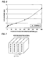
- the most influential factor in relation to this response is diffusibility of a gas to be measured within the moisture-sensitive layer and within the detection electrodes. Diffusion of gas will next be described according to Fick's law, with reference to the schematic view of FIG. 7 showing diffusion of gas within the moisture-sensitive layer.
- n 1 C 1 b
- n 2 C 2 b
- the number of atoms jumping from lattice plane 1 to lattice plane 2 is expressed by fn 1 . Since a simple cubic lattice involves six possible directions along which atoms jump, the number of atoms jumping from lattice plane 1 to lattice plane 2 is expressed by fn 1 /6.
- C 2 - C 1 (C 2 - C 1 ) can be expressed by use of a concentration gradient, as follows.
- C 2 - C 1 b*dC/dX
- the amount of diffusion can be adjusted by means of constant b, which depends on a moisture sensitive material to be used, mixing proportions among a plurality of moisture sensitive materials to be employed, the grain size of a moisture sensitive material to be used, or the like.
- the amount of diffusion can be adjusted by means of adjusting the distance along the X direction; i.e., by means of adjusting the thickness of the moisture-sensitive layer. The thinner the moisture-sensitive layer, the greater the amount of diffusion. Increase in the amount of diffusion enhances response. Adjustment of the amount of diffusion through adjustment of the thickness of the moisture-sensitive layer, as employed by the humidity sensor of the present invention, can enhance response without involving change in moisture-sensing characteristic.
- the humidity sensor of the invention preferably is made of a metal oxide or compound oxide and comprises a protective layer for covering the detection electrode and the moisture-sensitive layer.
- This protective layer makes it possible to inhibit the deterioration of the moisture-sensitive layer by harmful materials contained in the atmosphere to be measured.
- a metal oxide or compound oxide exhibits a high heat resistance and thus can form a humidity sensor which exhibits an excellent durability even when the atmosphere to be measured has a temperature as high as higher than 800°C.
- the kind of the metal oxide or compound oxide to be used is not limited.
- the metal oxide or compound oxide there may be used alumina, spinnel, mullite, zirconia, titania, ceria, magnesia or the like.
- a ceramic which can difficultly undergo thermal shrinkage such as compound oxide (e.g., spinnel, mullite) is preferred.
- the protective layer is made of a porous material having a porosity of preferably from 20% to 80%, particularly from 30% to 70%.
- a porosity of the protective layer falls below 20%, the resulting protective layer is little permeable to moisture or the like, possibly deteriorating the responce of the humidity sensor to disadvantage.
- the porosity of the protective layer exceeds 80%, harmful materials can easily permeate the protective layer, making it occasionally impossible to sufficiently inhibit the deterioration of the moisture-sensitive layer.
- the method for forming this protective layer is not specifically limited.
- the protective layer can be formed by an ordinary method for forming a metal oxide film or compound oxide film.
- the protective layer is preferably formed by a screen printing method, transfer method, spray coating method or dip coating method.
- the protective layer if the element is formed by opposing electrodes, is formed after the formation of the aforementioned electrodes so as to cover the element at least on the surface of the upper electrode and the area of the moisture-sensitive layer on which the upper electrode is not laminated. In this arrangement, the moisture-sensitive layer is sufficiently protected.
- the element is preferably covered by the protective layer on the whole surface thereof, including the edge face of the moisture-sensitive layer and the upper electrode. In other words, it is preferred that the peripheral edge of the protective layer be formed in contact with the surface of the insulating substrate. In this arrangement, the resulting humidity sensor can be provided with a better durability.
- the thickness of the protective layer is preferably from 10 ⁇ m to 200 ⁇ m, particularly from 20 ⁇ m to 100 ⁇ m. When the thickness of the protective layer is too small, harmful materials cannot be sufficiently caught. On the contrary, when the thickness of the protective layer exceeds 200 ⁇ m, the resulting protective layer is liable to peeling from the upper electrode or the like to disadvantage.
- the sensor of the invention is characterized in that it is used to detect the state of a device for purifying the exhaust gas from an internal combustion engine (e.g., adsorbing material capable of adsorbing hydrocarbon and water content, exhaust gas purifying material such as three-way catalyst, HC trapping material comprising zeolite or the like, HC adsorption catalyst comprising a three-way catalyst and an HC trapping material) from the change of amount of water vapor in the exhaust gas.
- an internal combustion engine e.g., adsorbing material capable of adsorbing hydrocarbon and water content, exhaust gas purifying material such as three-way catalyst, HC trapping material comprising zeolite or the like, HC adsorption catalyst comprising a three-way catalyst and an HC trapping material
- the invention discloses the usage of humidity sensor by way of example.
- this type of an exhaust gas purifying device is used to purify the exhaust gas from an internal combustion engine.
- the exhaust gas purifying device comprising an adsorbing material or the like deteriorates, the amount of water vapor downstream from the exhaust gas purifying device varies. Accordingly, by measuring the amount of water vapor in the exhaust gas downstream from the exhaust gas purifying device, the deterioration state of the exhaust gas purifying device can be detected.
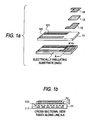
- FIG. 1a is a perspective view showing an example of a humidity sensor 1 according to the present invention.
- FIG. 1b is a cross-sectional view taken along line A-A' in FIG. 1a.
- An insulating substrate 11 is formed from Al 2 O 3 , and has a thickness of 1.6 mm, a width of 4 mm, and a length of 45 mm.
- a heater 111 which is formed from Pt and assumes the shape of a bent strip is provided in the insulating substrate to be located at least partly below a moisture-sensitive layer at a position which is about 1/4 the thickness of the substrate distant from the lower surface of the substrate.
- a temperature measurement resistor 112 which is formed from Pt and assumes the shape of a bent strip is provided in the insulating substrate to be located at least partly below the moisture-sensitive layer at a position which is about 1/4 the thickness of the substrate distant from the upper surface of the substrate.
- a lower electrode 12 formed from Pt is joined to the upper surface at one longitudinal end of the insulating substrate.
- the lower electrode 12 is formed by a porous material having an average grain diameter of from 2 ⁇ m to 3 ⁇ m and pores having a diameter of from 0.5 ⁇ m to 10 ⁇ m and comprising yttria-stabilized zirconia incorporated therein in an amount of 12% by weight.
- the lower electrode 12 has a thickness of 15 ⁇ m, a width of 2 mm, and a length of 2.5 mm.
- a portion of the lower electrode 12 is connected to an output lead wire 121.
- the lower surface of a moisture-sensitive layer 13 formed from a moisture sensitive ceramic material containing Al 2 O 3 and predetermined amounts of TiO 2 and SnO 2 is joined to the entire surface of the lower electrode and a portion of the insulating substrate.
- the moisture-sensitive layer 13 is formed by a porous material having an average grain diameter of from 0.05 ⁇ m to 0.1 ⁇ m and comprising pores having a diameter of from 0.05 ⁇ m to 0.2 ⁇ mm.
- the moisture-sensitive layer 13 has a thickness of 30 ⁇ m, a width of 2.5 mm, and a length of 2.5 mm.
- An upper electrode 14 formed from Pt is joined to the upper surface of the moisture-sensitive layer which is opposite the lower electrode.
- the upper electrode 14 is formed by a porous material having an average grain diameter of from 2 ⁇ m to 3 ⁇ m and pores with a diameter of from 0.5 ⁇ m to 10 ⁇ m and comprising a yttria-stabilized zirconia incorporated therein in an amount of 12% by weight.
- the upper electrode 14 has a thickness of 15 ⁇ m, a width of 2 mm, and a length of 2.5 mm. A portion of the upper electrode extends to be connected to an output lead wire 141.
- the heater is connected to a power supply source, and the temperature measurement resistor is connected to a temperature detection circuit.
- the power supply source, the temperature detection circuit, and lead wires connected thereto are not illustrated for the sake of simplicity.
- FIGS. 2a and 2b are a perspective view showing another example of the humidity sensor 1 according to the present invention.
- FIG. 2a is a perspective view showing comblike electrodes formed on the insulating substrate.
- Fig. 2c is a cross-sectional view of the humidity sensor taken along line A-A' in FIG. 2b.
- comblike electrodes 15 formed from Pt are joined to the upper surface at one longitudinal end of the insulating substrate 11.
- Each of the comblike electrodes 15 has a thickness of 15 ⁇ m, a width of 2 mm, a length of 2.5 mm, and a comb tooth width of 100 ⁇ m. End portions of the electrodes are connected to corresponding output lead wires 151 and 152.
- the lower surface of a moisture-sensitive layer 13 formed from a moisture sensitive ceramic material containing Al 2 O 3 and predetermined amounts of TiO 2 and SnO 2 is joined to the entire surface of the comblike electrodes and a portion of the insulating substrate.
- a slurry containing alumina powder was prepared, and alumina green sheets A, B, C, and D (the entirety to serve as an insulating substrate 11 after firing) (thickness of each sheet: 400 ⁇ m) were formed from the slurry through a doctor blade process. Thereafter, through screen printing, a Pt-containing paste for a heater was applied onto the upper surface of the alumina green sheet A, to thereby form a heater pattern (to serve as a heater 111 and wires to be connected to the power supply source (not illustrated) after firing).
- a Pt-containing paste for a temperature measurement resistor was applied onto a first surface of the alumina green sheet C, to thereby form a temperature measurement resistor pattern (to serve as a temperature measurement resistor 112 and wires to be connected to the temperature detection circuit (not illustrated) after firing). Furthermore, through screen printing, a Pt-containing paste for output lead wires was applied onto a first surface of the alumina green sheet D, to thereby form output lead wire patterns (to serve as output lead wires 121 and 141 after firing).
- the alumina green sheets A to D were stacked on one another, such that 1) a second surface of the alumina green sheet D (the output lead wire patterns having been formed on the first surface thereof) came into contact with the first surface of the alumina green sheet C on which the temperature measurement resistor pattern had been formed; 2) a second surface of the alumina green sheet C came into contact with a first surface of the alumina green sheet B, the sheet B serving as an insulating layer for further reliably preventing contact between the heater pattern and the temperature measurement resistor pattern; and 3) a second surface of the alumina green sheet B came into contact with a first surface of the alumina green sheet A on which the heater pattern has been formed.
- the resultant product was pressed to thereby form a laminate. Thereafter, the resultant laminate was fired at 1,550°C for two hours, to thereby produce an insulating substrate in which a heater and a temperature measurement resistor were provided.
- the dimensions of the green sheets were determined such that 10 insulating substrates could be produced. Heater patterns, temperature measurement resistor patterns, and output lead wire patterns were formed in a number corresponding to the number of the substrates.
- the green sheets were stacked as described above, and the resultant laminate was cut into green substrates. The resultant green substrates were fired to thereby produce 10 insulating substrates simultaneously.
- the moisture-sensitive layer, the detection electrodes, etc. were formed according to the following steps (i)-(iii).
- a platinum paste was applied, through printing, onto the surface of the insulating substrate 11 produced in (1) so as to form a lower electrode pattern having a thickness of 15 ⁇ m, a width of 2 mm, and a length of 2.5 mm.
- the resultant product was dried at 60°C for one hour and was then fired at 1,200°C for 10 minutes, to thereby form the lower electrode 12.
- a paste for a moisture-sensitive layer which had been prepared from a powder mixture containing Al 2 O 3 powder and predetermined amounts of TiO 2 powder and SnO 2 powder, was applied, through printing, onto the surface of the lower electrode formed in (i). Thereafter, the resultant product was fired at 1,200°C for two hours, to thereby form a moisture-sensitive layer 13 having a thickness of 30 ⁇ m, a width of 2.5 mm, and a length of 2.5 mm.
- a platinum paste was applied, through printing, onto the surface of the moisture-sensitive layer formed in (ii) so as to form an upper electrode pattern having a thickness of 15 ⁇ m, a width of 2 mm, and a length of 2.5 mm.
- a pattern for securing conduction between the upper electrode and the output lead wire 141 was printed onto one end face of the moisture-sensitive layer and onto the surface of the insulating substrate.
- the resultant product was dried at 60°C for one hour and was then fired at 1,200°C for 10 minutes, to thereby form the upper electrode 14, etc.
- the humidity sensor was fabricated the humidity sensor.
- a humidity sensor of Example 2 was fabricated in a manner similar to that of Example 1 except for the following.
- a platinum paste was applied, through printing, onto the surface of the insulating substrate, which had been produced in a similar manner as in the case of fabrication of the humidity sensor of Example 1, so as to form comblike electrode patterns.
- the resultant product was dried and was then fired to thereby form the comblike electrodes.
- the paste for a moisture-sensitive layer which was used in fabrication of the humidity sensor of Example 1 was applied, through printing, onto the surface of the comblike electrodes. The resultant product was fired to thereby form the moisture-sensitive layer.
- a humidity sensor of Comparative Example 1 was also fabricated in a manner similar to that of Example 1 except that a moisture-sensitive layer having a thickness of 400 ⁇ m was formed by a pelleting process.
- a sensor output was measured under the following conditions: temperature 20°C; and relative humidity 10%, 20%, 40%, 60%, 80%, and 90%. In order to eliminate condensed water, the sensors were heated. After a measured resistance was stabilized, a sensor resistance was measured at the above humidity values, to thereby evaluate the sensors. The results are shown in FIG. 3.
- a sensor output was measured at a temperature of 20°C while relative humidity was varied over the range of 20% to 80%.
- the sensors were heated. After a measured resistance was stabilized, a change in sensor resistance was measured while humidity was varied, to thereby evaluate the sensors.
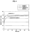
- the vertical axis indicates a sensor output that is reduced to humidity on the basis of resistance. Response characteristics of the sensors were compared on the basis of response time at the time of 63.2% response.
- the humidity sensors of Example 1 and Comparative Example 1 exhibit substantially similar moisture-sensing characteristics.
- the sensor of Example 1 can reduce sensor resistance to about 1/30 that of Comparative Example 1.
- the humidity sensors of Examples 1 and 2 exhibit a response time which is a little in excess of 1 sec, thereby proving that the sensors exhibit excellent response.
- the humidity sensor of Comparative Example 1 exhibits a response time of near 9 sec, indicating response thereof is greatly impaired because of the moisture-sensitive layer being thick.
- the thickness of the moisture-sensitive layer reduces, response is enhanced; and at a thickness of the moisture-sensitive layer of not greater than 100 ⁇ m, response time is not longer than 2 sec, indicating that the sensor exhibits excellent response. In this manner, as the moisture-sensitive layer becomes thinner, response is enhanced.
- the thickness of the moisture-sensitive layer is determined in consideration of such factors.
- a protective layer 150 made of spinnel may be formed on the upper and side surfaces of the upper electrode and the moisture-sensitive layer.
- the peripheral edge of the protective layer is connected to the upper surface of the insulating substrate.
- the upper electrode, the moisture-sensitive layer and the lower electrode are entirely covered by the protective layer.
- the thickness of the protective layer is 30 ⁇ m.
- the porosity of the protective layer is 55%.
- the formation of the protective layer 150 is accomplished by the following method.
- a spinnel powder is stirred in a dry process for 1 hour.
- an acetone solution of ethyl cellosolve and n-butyl acetate in a proportion of 1/10 and 4.3/10, respectively, by mass.
- the mixture was then stirred in a wet process for 1 hour to prepare a paste for protective layer.
- the paste for protective layer was printed on the upper surface of the upper electrode formed at the aforementioned step (3) to form a pattern for protective layer to a thickness of 30 ⁇ m.
- the coated material was dried at a temperature of 60°C for 1 hour, and kept and calcined at a temperature of 1,200°C for 2 hours to form a protective layer 15.
- a humidity sensor By thus forming a protective layer having an excellent heat resistance made of a metal oxide or compound oxide, a humidity sensor can be obtained which exhibits an excellent durability because it undergoes no deterioration of properties due to harmful materials contained in the atmosphere to be measured even at high temperatures and gives a stabilized output even when used in an atmosphere having a low oxygen concentration and contains a reducing gas. Accordingly, the humidity sonsor of the invention is useful particularly for the detection of the moisture content in a specific atmosphere as in the exhaust pipe of automobile, etc. or in fuel cell.
- the present invention can provide a humidity sensor which produces stable output and exhibits excellent durability even in application to measurement in an atmosphere which exhibits low oxygen concentration, presence of a reducing gas, high temperature, and significant variations in, for example, gas flow rate and gas flow velocity.
- the humidity sensor can be fabricated by use of conventional materials and a conventional method, without need of special materials, apparatus, oparation, etc.
- the humidity sensor is particularly useful for detecting the moisture content of a specific atmosphere, as in an exhaust pipe of a vehicle or as around an electrode of a fuel cell.
Landscapes
- Chemical & Material Sciences (AREA)
- Chemical Kinetics & Catalysis (AREA)
- Electrochemistry (AREA)
- Physics & Mathematics (AREA)
- Health & Medical Sciences (AREA)
- Life Sciences & Earth Sciences (AREA)
- Analytical Chemistry (AREA)
- Biochemistry (AREA)
- General Health & Medical Sciences (AREA)
- General Physics & Mathematics (AREA)
- Immunology (AREA)
- Pathology (AREA)
- Investigating Or Analyzing Materials By The Use Of Fluid Adsorption Or Reactions (AREA)
Abstract
Description
- 1:
- humidity sensor
- 11:
- insulating substrate
- 111:
- heater
- 112:
- temperature measurement resistor
- 12:
- lower electrode
- 13:
- moisture-sensitive layer
- 14:
- upper electrode
- 15:
- comblike electrode
- 121, 141, 151, 152:
- output lead wires connected to electrodes
- 2:
- air cylinder
- 31:
- mass flow (wet)
- 32:
- mass flow (dry)
- 4:
- thermostatic chamber
- 51:
- first saturated bath
- 52:
- second saturated bath
- 6:
- evaluation container
- 7:
- temperature-humidity detection apparatus
- 150:
- protective layer
| Measured value | Response characteristic [63.2% (τ=1)] | |||
| Humidity 20% | Humidity 80% | Ultimate humidity | Ultimate time | |
| Example 1 | 21.84 | 75.78 | 55.82% | 1.4 sec |
| Example 2 | 23.55 | 75.73 | 56.42% | 1.2 sec |
| Comparative Example 1 | 24.55 | 76.98 | 57.58% | 8.6 sec |
Claims (16)
- A humidity sensor comprising an insulating substrate, a detection electrodes and a moisture-sensitive layer, wherein the moisture-sensitive layer is a porous layer and has a thickness not greater than 200 µm.
- The humidity sensor according to claim 1, wherein the moisture-sensitive layer has a thickness not greater than 50 µm.
- The humidity sensor according to claim 1 or 2, wherein each of the detection electrodes comprises a noble metal and is formed of a porous material which has an average pore size greater than that of the moisture-sensitive layer.
- The humidity sensor according to any one of claims 1 to 3, wherein the detection electrodes comprises a lower electrode and an upper electrode; the lower electrode overlies the insulating substrate; the moisture-sensitive layer overlies the lower electrode such that an entire surface of the lower electrode except the surface covered with the insulating substrate is covered with the moisture-sensitive layer; and the upper electrode overlies the moisture-sensitive layer at a same position with the lower electrode in laminating direction.
- The humidity sensor according to any one of claims 1 to 3, wherein a planar shape of the detection electrodes is a comblike planar shape; the detection electrodes overlies the insulating substrate; and the moisture-sensitive layer overlies the detection electrodes such that an entire surface of the detection electrodes except the surface covered with the insulating substrate is covered with the moisture-sensitive layer.
- The humidity sensor according to any one of claims 1 to 5, wherein a heater is provided in the insulating substrate.
- The humidity sensor according to any one of claims 1 to 6, wherein a temperature measurement resistor is provided in the insulating substrate.
- The humidity sensor according to claim 6, wherein the heater is positioned at least partly within a region formed by projecting the moisture-sensitive layer in laminating direction.
- The humidity sensor according to claim 7, wherein the temperature measurement resistor is positioned at least partly within a region formed by projecting the moisture-sensitive layer in laminating direction.
- The humidity sensor according to any one of claims 1 to 9, wherein the diameter of pores in the detection electrodes is from 0.5 µm to 20 µm.
- The humidity sensor according to any one of claims 1 to 10, wherein the diameter of pores in the moisture-sensitive layer is from 0.05 µm to 1 µm.
- The humidity sensor according to any one of claims 1 to 11, wherein the detection electrodes comprises particulate ceramic in an amount of from 1 to 20% by weight
- The humidity sensor according to claim.12, wherein the particulate ceramic is particulate alumina or particulate zirconia.
- The humidity sensor according to any one of claims 1 to 13, further comprising a protective coat that covers the detection electrodes and the moisture-sensitive layer, wherein the protective coat comprises one of a metal oxide and a compound oxide.
- The humidity sensor according to claim 14, wherein the protective coat has a porosity of from 20% to 80%.
- The humidity sensor according to claim 14 or 15, wherein the protective coat has a thickness of from 10 µm to 200 µm.
Applications Claiming Priority (4)
| Application Number | Priority Date | Filing Date | Title |
|---|---|---|---|
| JP2001165319 | 2001-05-31 | ||
| JP2001165318 | 2001-05-31 | ||
| JP2001165319A JP2002357581A (en) | 2001-05-31 | 2001-05-31 | Humidity sensor |
| JP2001165318A JP2002357579A (en) | 2001-05-31 | 2001-05-31 | Humidity sensor |
Publications (3)
| Publication Number | Publication Date |
|---|---|
| EP1262767A2 true EP1262767A2 (en) | 2002-12-04 |
| EP1262767A3 EP1262767A3 (en) | 2003-07-16 |
| EP1262767B1 EP1262767B1 (en) | 2011-02-16 |
Family
ID=26616139
Family Applications (1)
| Application Number | Title | Priority Date | Filing Date |
|---|---|---|---|
| EP02011947A Expired - Lifetime EP1262767B1 (en) | 2001-05-31 | 2002-05-29 | Humidity sensor |
Country Status (3)
| Country | Link |
|---|---|
| US (1) | US6812821B2 (en) |
| EP (1) | EP1262767B1 (en) |
| DE (1) | DE60239174D1 (en) |
Cited By (3)
| Publication number | Priority date | Publication date | Assignee | Title |
|---|---|---|---|---|
| WO2009070888A1 (en) * | 2007-12-07 | 2009-06-11 | Esi Environmental Sensors Inc. | Moisture sensor |
| EP1482306A3 (en) * | 2003-05-30 | 2012-01-04 | Ngk Spark Plug Co., Ltd | Humidity sensor and method of using the humidity sensor |
| CN115753909A (en) * | 2017-04-05 | 2023-03-07 | 松下控股株式会社 | Gas sensor |
Families Citing this family (35)
| Publication number | Priority date | Publication date | Assignee | Title |
|---|---|---|---|---|
| US7132661B2 (en) * | 2000-08-28 | 2006-11-07 | Spectrasensors, Inc. | System and method for detecting water vapor within natural gas |
| JP4172576B2 (en) * | 2001-08-31 | 2008-10-29 | 本田技研工業株式会社 | Temperature control device for humidity sensor |
| US7115969B1 (en) * | 2002-09-13 | 2006-10-03 | Xsilogy, Inc. | Fixed parallel plate MEMS capacitor microsensor and microsensor array and method of making same |
| WO2006042546A1 (en) * | 2004-10-18 | 2006-04-27 | Senmatic A/S | A humidity sensor and a method for manufacturing the same |
| US20070030111A1 (en) * | 2005-08-02 | 2007-02-08 | Beck David B | Humidity sensor |
| US7373819B2 (en) * | 2005-09-30 | 2008-05-20 | Honeywell International Inc. | Stress sensitive humidity sensor based on a MEMS structure |
| US7573365B2 (en) * | 2005-12-12 | 2009-08-11 | Sensitron, Inc. | Humidity sensor |
| JP5112639B2 (en) * | 2006-03-06 | 2013-01-09 | トウプラスエンジニアリング株式会社 | Humidity sensor |
| US20070221132A1 (en) * | 2006-03-24 | 2007-09-27 | General Electric Company | Composition, coating, coated article, and method |
| US7679059B2 (en) * | 2006-04-19 | 2010-03-16 | Spectrasensors, Inc. | Measuring water vapor in hydrocarbons |
| US7511802B2 (en) | 2006-05-26 | 2009-03-31 | Spectrasensors, Inc. | Measuring trace components of complex gases using gas chromatography/absorption spectrometry |
| TWI314989B (en) * | 2006-06-23 | 2009-09-21 | Fego Prec Ind Co Ltd | Humidity sensor having temperature compensation self-comparing and manufacturing method therefore |
| JP4882732B2 (en) * | 2006-12-22 | 2012-02-22 | 株式会社デンソー | Semiconductor device |
| US7508521B2 (en) * | 2007-03-14 | 2009-03-24 | Spectrasensors, Inc. | Pressure-invariant trace gas detection |
| AU2008240146B2 (en) * | 2007-04-11 | 2013-10-17 | Spectrasensors, Inc. | Reactive gas detection in complex backgrounds |
| FR2928551A1 (en) * | 2008-03-14 | 2009-09-18 | Gambro Lundia Ab | PROBE FOR LEAK DETECTION OF MULTI-LAYER FLUID |
| FR2928550A1 (en) * | 2008-03-14 | 2009-09-18 | Gambro Lundia Ab | PROBE FOR FLUID LEAK DETECTION WITH SPECIFIC DISTAL PART |
| US20100307238A1 (en) * | 2009-06-05 | 2010-12-09 | The Governors Of The University Of Alberta | Humidity sensor and method of manufacturing the same |
| US8471304B2 (en) * | 2010-06-04 | 2013-06-25 | Carnegie Mellon University | Method, apparatus, and system for micromechanical gas chemical sensing capacitor |
| US9176089B2 (en) * | 2013-03-29 | 2015-11-03 | Stmicroelectronics Pte Ltd. | Integrated multi-sensor module |
| DE102013211378B4 (en) * | 2013-06-18 | 2021-05-20 | Robert Bosch Gmbh | Micromechanical humidity sensor device and corresponding manufacturing process as well as micromechanical sensor arrangement |
| DE102014200060A1 (en) | 2013-08-28 | 2015-03-19 | Micro-Epsilon Messtechnik Gmbh & Co. Kg | Sensor element and sensor with a corresponding sensor element |
| US10643008B2 (en) | 2014-11-11 | 2020-05-05 | Spectrasensors, Inc. | Target analyte detection and quantification in sample gases with complex background compositions |
| US10083883B2 (en) * | 2016-06-20 | 2018-09-25 | Applied Materials, Inc. | Wafer processing equipment having capacitive micro sensors |
| US9725302B1 (en) * | 2016-08-25 | 2017-08-08 | Applied Materials, Inc. | Wafer processing equipment having exposable sensing layers |
| WO2018062379A1 (en) * | 2016-09-30 | 2018-04-05 | ミツミ電機株式会社 | Humidity sensor |
| JP6919176B2 (en) * | 2016-10-28 | 2021-08-18 | 株式会社デンソー | Air physical quantity sensor |
| CN106501330A (en) * | 2016-12-30 | 2017-03-15 | 福建澳泰自动化设备有限公司 | A kind of High Temperature High Pressure relative humidity measurement method and system |
| KR102007446B1 (en) * | 2018-05-21 | 2019-10-21 | 해성디에스 주식회사 | Sensor unit, temperature sensor including the same, method of manufacturing the sensor unit, and temperature sensor manufactured using the same |
| TWM569412U (en) * | 2018-08-07 | 2018-11-01 | 捷騰光電股份有限公司 | Drying device for temperature and humidity sensing module |
| WO2020166616A1 (en) | 2019-02-15 | 2020-08-20 | 国立研究開発法人産業技術総合研究所 | Humidity-sensitive composite material and humidity sensor |
| CN113538871B (en) * | 2021-07-20 | 2022-06-28 | 山西新华防化装备研究院有限公司 | Failure alarm device and method for liquid-tight protective clothing |
| TWI874807B (en) * | 2022-08-25 | 2025-03-01 | 成百明 | Manufacturing method of liquid leakage sensor |
| JP2024066243A (en) * | 2022-11-01 | 2024-05-15 | ローム株式会社 | Hydrogen Detection System |
| CN115931984B (en) * | 2022-11-29 | 2026-06-16 | 电子科技大学长三角研究院(湖州) | A paper-based humidity sensor and its printing preparation method |
Family Cites Families (25)
| Publication number | Priority date | Publication date | Assignee | Title |
|---|---|---|---|---|
| US3691301A (en) * | 1970-12-14 | 1972-09-12 | Bell Telephone Labor Inc | Switching system arranged for time restricted flat rate station-to-station toll calling |
| AU5805873A (en) * | 1972-07-25 | 1975-01-16 | Koichi Sugaya | Humidity sensor electrode assembly |
| US4017820A (en) * | 1975-07-25 | 1977-04-12 | Illinois Tool Works Inc. | Humidity sensor with multiple electrode layers separated by a porous monolithic ceramic dielectric structure |
| US4277742A (en) * | 1977-01-31 | 1981-07-07 | Panametrics, Inc. | Absolute humidity sensors and methods of manufacturing humidity sensors |
| EP0013022B1 (en) * | 1978-12-26 | 1984-03-28 | Matsushita Electric Industrial Co., Ltd. | Humidity detecting apparatus using a humidity detecting resistor ceramic element |
| FR2498329A1 (en) * | 1981-01-19 | 1982-07-23 | Commissariat Energie Atomique | THIN DIELECTRIC CAPACITIVE HYGROMETER AND METHOD OF MANUFACTURING THE SAME |
| US4356150A (en) * | 1981-05-15 | 1982-10-26 | Honeywell Inc. | Humidity sensor with electrical rejection of contaminants |
| DE3224920C2 (en) * | 1981-07-08 | 1986-11-20 | Sharp K.K., Osaka | Moisture-sensitive resistance element |
| JPS5873852A (en) * | 1981-10-28 | 1983-05-04 | Hitachi Ltd | condensation sensor |
| US4656455A (en) * | 1984-07-20 | 1987-04-07 | Toyama Prefecture | Humidity-sensing element |
| US4666628A (en) * | 1984-12-20 | 1987-05-19 | Mitsubishi Denki Kabushiki Kaisha | Moisture sensitive material and process for its production |
| CN85100146B (en) * | 1985-04-01 | 1987-06-10 | 清华大学 | Heat-moisture-gas multifunctional sensitive ceramic element and its manufacturing method |
| JPH0517650Y2 (en) * | 1986-01-31 | 1993-05-12 | ||
| GB2220074B (en) * | 1988-06-27 | 1992-01-08 | Seiko Epson Corp | Humidity sensor |
| JPH02306151A (en) * | 1989-05-19 | 1990-12-19 | Seiko Epson Corp | humidity sensor element |
| DE3941837C2 (en) * | 1989-12-19 | 1994-01-13 | Bosch Gmbh Robert | Resistance sensor for detecting the oxygen content in gas mixtures and process for its production |
| US5136274A (en) * | 1990-02-01 | 1992-08-04 | Mitsubishi Gas Chemical Company, Inc. | Humidity sensor |
| US5367283A (en) * | 1992-10-06 | 1994-11-22 | Martin Marietta Energy Systems, Inc. | Thin film hydrogen sensor |
| FI98861C (en) * | 1994-01-18 | 1997-08-25 | Vaisala Oy | A method of manufacturing a microporous gas-permeable electrode and a microporous gas-permeable electrode |
| DE4433102A1 (en) * | 1994-09-16 | 1996-03-21 | Fraunhofer Ges Forschung | Electrode arrangement for signal detection of gas sensitive layers |
| US5792938A (en) * | 1996-12-13 | 1998-08-11 | Panametrics, Inc. | Humidity sensor with differential thermal detection and method of sensing |
| JPH10239264A (en) * | 1997-02-25 | 1998-09-11 | Sanriki Kogyo Kk | Electric resistance type humidity sensor |
| CN1105911C (en) * | 1997-05-02 | 2003-04-16 | 株式会社山武 | Humidity sensitive element and mfg. method therefor |
| US6120891A (en) * | 1997-10-29 | 2000-09-19 | Board Of Regemts. The University Of Texas System | Mesoporous transition metal oxide thin films and methods of making and uses thereof |
| JP2002116172A (en) * | 2000-10-10 | 2002-04-19 | Ngk Spark Plug Co Ltd | Humidity sensor |
-
2002
- 2002-05-29 DE DE60239174T patent/DE60239174D1/en not_active Expired - Lifetime
- 2002-05-29 EP EP02011947A patent/EP1262767B1/en not_active Expired - Lifetime
- 2002-05-30 US US10/157,134 patent/US6812821B2/en not_active Expired - Fee Related
Cited By (4)
| Publication number | Priority date | Publication date | Assignee | Title |
|---|---|---|---|---|
| EP1482306A3 (en) * | 2003-05-30 | 2012-01-04 | Ngk Spark Plug Co., Ltd | Humidity sensor and method of using the humidity sensor |
| WO2009070888A1 (en) * | 2007-12-07 | 2009-06-11 | Esi Environmental Sensors Inc. | Moisture sensor |
| US8400170B2 (en) | 2007-12-07 | 2013-03-19 | Esi Environmental Sensors Inc. | Moisture sensor |
| CN115753909A (en) * | 2017-04-05 | 2023-03-07 | 松下控股株式会社 | Gas sensor |
Also Published As
| Publication number | Publication date |
|---|---|
| US20020190840A1 (en) | 2002-12-19 |
| DE60239174D1 (en) | 2011-03-31 |
| EP1262767A3 (en) | 2003-07-16 |
| EP1262767B1 (en) | 2011-02-16 |
| US6812821B2 (en) | 2004-11-02 |
Similar Documents
| Publication | Publication Date | Title |
|---|---|---|
| US6812821B2 (en) | Humidity sensor | |
| US6883371B2 (en) | Humidity sensor | |
| KR100337102B1 (en) | Sensor for detecting nitrogen oxide | |
| US4863583A (en) | Electrode structure of an oxygen sensing element | |
| EP0853762B1 (en) | Gas sensor and manufacturing process thereof | |
| US6660145B2 (en) | Oxygen sensor element | |
| US20070151851A1 (en) | Gas sensor element | |
| US5800689A (en) | Oxygen concentration detector | |
| EP1346210A2 (en) | Gas sensor | |
| JP2002048758A (en) | Gas sensor element and manufacturing method thereof | |
| JP2011089796A (en) | Gas sensor element, method for manufacturing the same, and gas sensor | |
| EP0159905B1 (en) | Device for detecting concentration of oxygen in exhaust gas | |
| US4786476A (en) | Gas sensor element using porously fired mass of titania | |
| EP0059933B1 (en) | Solid electrolyte oxygen sensing element of laminated structure with gas diffusion layer on outer electrode | |
| JP3950812B2 (en) | Gas sensor and manufacturing method thereof | |
| US5707503A (en) | Oxygen sensor element | |
| CN114026413B (en) | Gas sensor and method for manufacturing the same | |
| JP4880931B2 (en) | How to use a sensor with a platform chip | |
| JPH09113480A (en) | Oxygen sensor element | |
| JP4615788B2 (en) | Cleaning method for variable resistance gas sensor | |
| US4946577A (en) | Oxygen sensor | |
| JP4040550B2 (en) | Humidity sensor and manufacturing method thereof | |
| JP2002357579A (en) | Humidity sensor | |
| JP4402282B2 (en) | Method for manufacturing flammable gas sensor element | |
| JP2897471B2 (en) | Oxide semiconductor oxygen concentration sensor |
Legal Events
| Date | Code | Title | Description |
|---|---|---|---|
| PUAI | Public reference made under article 153(3) epc to a published international application that has entered the european phase |
Free format text: ORIGINAL CODE: 0009012 |
|
| AK | Designated contracting states |
Kind code of ref document: A2 Designated state(s): AT BE CH CY DE DK ES FI FR GB GR IE IT LI LU MC NL PT SE TR |
|
| AX | Request for extension of the european patent |
Free format text: AL;LT;LV;MK;RO;SI |
|
| PUAL | Search report despatched |
Free format text: ORIGINAL CODE: 0009013 |
|
| AK | Designated contracting states |
Designated state(s): AT BE CH CY DE DK ES FI FR GB GR IE IT LI LU MC NL PT SE TR |
|
| AX | Request for extension of the european patent |
Extension state: AL LT LV MK RO SI |
|
| 17P | Request for examination filed |
Effective date: 20040116 |
|
| AKX | Designation fees paid |
Designated state(s): DE FR |
|
| 17Q | First examination report despatched |
Effective date: 20060710 |
|
| GRAP | Despatch of communication of intention to grant a patent |
Free format text: ORIGINAL CODE: EPIDOSNIGR1 |
|
| GRAS | Grant fee paid |
Free format text: ORIGINAL CODE: EPIDOSNIGR3 |
|
| GRAA | (expected) grant |
Free format text: ORIGINAL CODE: 0009210 |
|
| AK | Designated contracting states |
Kind code of ref document: B1 Designated state(s): DE FR |
|
| REF | Corresponds to: |
Ref document number: 60239174 Country of ref document: DE Date of ref document: 20110331 Kind code of ref document: P |
|
| REG | Reference to a national code |
Ref country code: DE Ref legal event code: R096 Ref document number: 60239174 Country of ref document: DE Effective date: 20110331 |
|
| PLBE | No opposition filed within time limit |
Free format text: ORIGINAL CODE: 0009261 |
|
| STAA | Information on the status of an ep patent application or granted ep patent |
Free format text: STATUS: NO OPPOSITION FILED WITHIN TIME LIMIT |
|
| 26N | No opposition filed |
Effective date: 20111117 |
|
| REG | Reference to a national code |
Ref country code: DE Ref legal event code: R097 Ref document number: 60239174 Country of ref document: DE Effective date: 20111117 |
|
| PGFP | Annual fee paid to national office [announced via postgrant information from national office to epo] |
Ref country code: FR Payment date: 20140509 Year of fee payment: 13 Ref country code: DE Payment date: 20140521 Year of fee payment: 13 |
|
| REG | Reference to a national code |
Ref country code: DE Ref legal event code: R119 Ref document number: 60239174 Country of ref document: DE |
|
| REG | Reference to a national code |
Ref country code: FR Ref legal event code: ST Effective date: 20160129 |
|
| PG25 | Lapsed in a contracting state [announced via postgrant information from national office to epo] |
Ref country code: DE Free format text: LAPSE BECAUSE OF NON-PAYMENT OF DUE FEES Effective date: 20151201 |
|
| PG25 | Lapsed in a contracting state [announced via postgrant information from national office to epo] |
Ref country code: FR Free format text: LAPSE BECAUSE OF NON-PAYMENT OF DUE FEES Effective date: 20150601 |