EP1262640A1 - Abgasstrang einer Brennkraftmaschine, insbesondere Dieselmotor eines Nutzfahrzeuges wie Lastkraftwagen oder Omnibus, mit integrierten Abgasnachbehandlungs- und Schalldämpfungsvorrichtungen - Google Patents
Abgasstrang einer Brennkraftmaschine, insbesondere Dieselmotor eines Nutzfahrzeuges wie Lastkraftwagen oder Omnibus, mit integrierten Abgasnachbehandlungs- und Schalldämpfungsvorrichtungen Download PDFInfo
- Publication number
- EP1262640A1 EP1262640A1 EP02006845A EP02006845A EP1262640A1 EP 1262640 A1 EP1262640 A1 EP 1262640A1 EP 02006845 A EP02006845 A EP 02006845A EP 02006845 A EP02006845 A EP 02006845A EP 1262640 A1 EP1262640 A1 EP 1262640A1
- Authority
- EP
- European Patent Office
- Prior art keywords
- exhaust
- exhaust gas
- silencer
- line according
- wall
- Prior art date
- Legal status (The legal status is an assumption and is not a legal conclusion. Google has not performed a legal analysis and makes no representation as to the accuracy of the status listed.)
- Granted
Links
Images




Classifications
-
- F—MECHANICAL ENGINEERING; LIGHTING; HEATING; WEAPONS; BLASTING
- F01—MACHINES OR ENGINES IN GENERAL; ENGINE PLANTS IN GENERAL; STEAM ENGINES
- F01N—GAS-FLOW SILENCERS OR EXHAUST APPARATUS FOR MACHINES OR ENGINES IN GENERAL; GAS-FLOW SILENCERS OR EXHAUST APPARATUS FOR INTERNAL-COMBUSTION ENGINES
- F01N13/00—Exhaust or silencing apparatus characterised by constructional features
- F01N13/08—Other arrangements or adaptations of exhaust conduits
-
- B—PERFORMING OPERATIONS; TRANSPORTING
- B01—PHYSICAL OR CHEMICAL PROCESSES OR APPARATUS IN GENERAL
- B01D—SEPARATION
- B01D53/00—Separation of gases or vapours; Recovering vapours of volatile solvents from gases; Chemical or biological purification of waste gases, e.g. engine exhaust gases, smoke, fumes, flue gases, aerosols
- B01D53/34—Chemical or biological purification of waste gases
- B01D53/92—Chemical or biological purification of waste gases of engine exhaust gases
- B01D53/94—Chemical or biological purification of waste gases of engine exhaust gases by catalytic processes
- B01D53/9445—Simultaneously removing carbon monoxide, hydrocarbons or nitrogen oxides making use of three-way catalysts [TWC] or four-way-catalysts [FWC]
- B01D53/9454—Simultaneously removing carbon monoxide, hydrocarbons or nitrogen oxides making use of three-way catalysts [TWC] or four-way-catalysts [FWC] characterised by a specific device
-
- F—MECHANICAL ENGINEERING; LIGHTING; HEATING; WEAPONS; BLASTING
- F01—MACHINES OR ENGINES IN GENERAL; ENGINE PLANTS IN GENERAL; STEAM ENGINES
- F01N—GAS-FLOW SILENCERS OR EXHAUST APPARATUS FOR MACHINES OR ENGINES IN GENERAL; GAS-FLOW SILENCERS OR EXHAUST APPARATUS FOR INTERNAL-COMBUSTION ENGINES
- F01N1/00—Silencing apparatus characterised by method of silencing
- F01N1/08—Silencing apparatus characterised by method of silencing by reducing exhaust energy by throttling or whirling
-
- F—MECHANICAL ENGINEERING; LIGHTING; HEATING; WEAPONS; BLASTING
- F01—MACHINES OR ENGINES IN GENERAL; ENGINE PLANTS IN GENERAL; STEAM ENGINES
- F01N—GAS-FLOW SILENCERS OR EXHAUST APPARATUS FOR MACHINES OR ENGINES IN GENERAL; GAS-FLOW SILENCERS OR EXHAUST APPARATUS FOR INTERNAL-COMBUSTION ENGINES
- F01N1/00—Silencing apparatus characterised by method of silencing
- F01N1/08—Silencing apparatus characterised by method of silencing by reducing exhaust energy by throttling or whirling
- F01N1/10—Silencing apparatus characterised by method of silencing by reducing exhaust energy by throttling or whirling in combination with sound-absorbing materials
-
- F—MECHANICAL ENGINEERING; LIGHTING; HEATING; WEAPONS; BLASTING
- F01—MACHINES OR ENGINES IN GENERAL; ENGINE PLANTS IN GENERAL; STEAM ENGINES
- F01N—GAS-FLOW SILENCERS OR EXHAUST APPARATUS FOR MACHINES OR ENGINES IN GENERAL; GAS-FLOW SILENCERS OR EXHAUST APPARATUS FOR INTERNAL-COMBUSTION ENGINES
- F01N1/00—Silencing apparatus characterised by method of silencing
- F01N1/24—Silencing apparatus characterised by method of silencing by using sound-absorbing materials
-
- F—MECHANICAL ENGINEERING; LIGHTING; HEATING; WEAPONS; BLASTING
- F01—MACHINES OR ENGINES IN GENERAL; ENGINE PLANTS IN GENERAL; STEAM ENGINES
- F01N—GAS-FLOW SILENCERS OR EXHAUST APPARATUS FOR MACHINES OR ENGINES IN GENERAL; GAS-FLOW SILENCERS OR EXHAUST APPARATUS FOR INTERNAL-COMBUSTION ENGINES
- F01N13/00—Exhaust or silencing apparatus characterised by constructional features
- F01N13/009—Exhaust or silencing apparatus characterised by constructional features having two or more separate purifying devices arranged in series
-
- F—MECHANICAL ENGINEERING; LIGHTING; HEATING; WEAPONS; BLASTING
- F01—MACHINES OR ENGINES IN GENERAL; ENGINE PLANTS IN GENERAL; STEAM ENGINES
- F01N—GAS-FLOW SILENCERS OR EXHAUST APPARATUS FOR MACHINES OR ENGINES IN GENERAL; GAS-FLOW SILENCERS OR EXHAUST APPARATUS FOR INTERNAL-COMBUSTION ENGINES
- F01N13/00—Exhaust or silencing apparatus characterised by constructional features
- F01N13/011—Exhaust or silencing apparatus characterised by constructional features having two or more purifying devices arranged in parallel
- F01N13/017—Exhaust or silencing apparatus characterised by constructional features having two or more purifying devices arranged in parallel the purifying devices are arranged in a single housing
-
- F—MECHANICAL ENGINEERING; LIGHTING; HEATING; WEAPONS; BLASTING
- F01—MACHINES OR ENGINES IN GENERAL; ENGINE PLANTS IN GENERAL; STEAM ENGINES
- F01N—GAS-FLOW SILENCERS OR EXHAUST APPARATUS FOR MACHINES OR ENGINES IN GENERAL; GAS-FLOW SILENCERS OR EXHAUST APPARATUS FOR INTERNAL-COMBUSTION ENGINES
- F01N3/00—Exhaust or silencing apparatus having means for purifying, rendering innocuous, or otherwise treating exhaust
- F01N3/02—Exhaust or silencing apparatus having means for purifying, rendering innocuous, or otherwise treating exhaust for cooling, or for removing solid constituents of, exhaust
- F01N3/021—Exhaust or silencing apparatus having means for purifying, rendering innocuous, or otherwise treating exhaust for cooling, or for removing solid constituents of, exhaust by means of filters
- F01N3/023—Exhaust or silencing apparatus having means for purifying, rendering innocuous, or otherwise treating exhaust for cooling, or for removing solid constituents of, exhaust by means of filters using means for regenerating the filters, e.g. by burning trapped particles
- F01N3/0231—Exhaust or silencing apparatus having means for purifying, rendering innocuous, or otherwise treating exhaust for cooling, or for removing solid constituents of, exhaust by means of filters using means for regenerating the filters, e.g. by burning trapped particles using special exhaust apparatus upstream of the filter for producing nitrogen dioxide, e.g. for continuous filter regeneration systems [CRT]
-
- F—MECHANICAL ENGINEERING; LIGHTING; HEATING; WEAPONS; BLASTING
- F01—MACHINES OR ENGINES IN GENERAL; ENGINE PLANTS IN GENERAL; STEAM ENGINES
- F01N—GAS-FLOW SILENCERS OR EXHAUST APPARATUS FOR MACHINES OR ENGINES IN GENERAL; GAS-FLOW SILENCERS OR EXHAUST APPARATUS FOR INTERNAL-COMBUSTION ENGINES
- F01N3/00—Exhaust or silencing apparatus having means for purifying, rendering innocuous, or otherwise treating exhaust
- F01N3/02—Exhaust or silencing apparatus having means for purifying, rendering innocuous, or otherwise treating exhaust for cooling, or for removing solid constituents of, exhaust
- F01N3/021—Exhaust or silencing apparatus having means for purifying, rendering innocuous, or otherwise treating exhaust for cooling, or for removing solid constituents of, exhaust by means of filters
- F01N3/033—Exhaust or silencing apparatus having means for purifying, rendering innocuous, or otherwise treating exhaust for cooling, or for removing solid constituents of, exhaust by means of filters in combination with other devices
-
- F—MECHANICAL ENGINEERING; LIGHTING; HEATING; WEAPONS; BLASTING
- F01—MACHINES OR ENGINES IN GENERAL; ENGINE PLANTS IN GENERAL; STEAM ENGINES
- F01N—GAS-FLOW SILENCERS OR EXHAUST APPARATUS FOR MACHINES OR ENGINES IN GENERAL; GAS-FLOW SILENCERS OR EXHAUST APPARATUS FOR INTERNAL-COMBUSTION ENGINES
- F01N3/00—Exhaust or silencing apparatus having means for purifying, rendering innocuous, or otherwise treating exhaust
- F01N3/02—Exhaust or silencing apparatus having means for purifying, rendering innocuous, or otherwise treating exhaust for cooling, or for removing solid constituents of, exhaust
- F01N3/021—Exhaust or silencing apparatus having means for purifying, rendering innocuous, or otherwise treating exhaust for cooling, or for removing solid constituents of, exhaust by means of filters
- F01N3/033—Exhaust or silencing apparatus having means for purifying, rendering innocuous, or otherwise treating exhaust for cooling, or for removing solid constituents of, exhaust by means of filters in combination with other devices
- F01N3/035—Exhaust or silencing apparatus having means for purifying, rendering innocuous, or otherwise treating exhaust for cooling, or for removing solid constituents of, exhaust by means of filters in combination with other devices with catalytic reactors
-
- F—MECHANICAL ENGINEERING; LIGHTING; HEATING; WEAPONS; BLASTING
- F01—MACHINES OR ENGINES IN GENERAL; ENGINE PLANTS IN GENERAL; STEAM ENGINES
- F01N—GAS-FLOW SILENCERS OR EXHAUST APPARATUS FOR MACHINES OR ENGINES IN GENERAL; GAS-FLOW SILENCERS OR EXHAUST APPARATUS FOR INTERNAL-COMBUSTION ENGINES
- F01N3/00—Exhaust or silencing apparatus having means for purifying, rendering innocuous, or otherwise treating exhaust
- F01N3/02—Exhaust or silencing apparatus having means for purifying, rendering innocuous, or otherwise treating exhaust for cooling, or for removing solid constituents of, exhaust
- F01N3/04—Exhaust or silencing apparatus having means for purifying, rendering innocuous, or otherwise treating exhaust for cooling, or for removing solid constituents of, exhaust using liquids
-
- F—MECHANICAL ENGINEERING; LIGHTING; HEATING; WEAPONS; BLASTING
- F01—MACHINES OR ENGINES IN GENERAL; ENGINE PLANTS IN GENERAL; STEAM ENGINES
- F01N—GAS-FLOW SILENCERS OR EXHAUST APPARATUS FOR MACHINES OR ENGINES IN GENERAL; GAS-FLOW SILENCERS OR EXHAUST APPARATUS FOR INTERNAL-COMBUSTION ENGINES
- F01N3/00—Exhaust or silencing apparatus having means for purifying, rendering innocuous, or otherwise treating exhaust
- F01N3/08—Exhaust or silencing apparatus having means for purifying, rendering innocuous, or otherwise treating exhaust for rendering innocuous
- F01N3/10—Exhaust or silencing apparatus having means for purifying, rendering innocuous, or otherwise treating exhaust for rendering innocuous by thermal or catalytic conversion of noxious components of exhaust
- F01N3/24—Exhaust or silencing apparatus having means for purifying, rendering innocuous, or otherwise treating exhaust for rendering innocuous by thermal or catalytic conversion of noxious components of exhaust characterised by constructional aspects of converting apparatus
- F01N3/28—Construction of catalytic reactors
- F01N3/2882—Catalytic reactors combined or associated with other devices, e.g. exhaust silencers or other exhaust purification devices
-
- F—MECHANICAL ENGINEERING; LIGHTING; HEATING; WEAPONS; BLASTING
- F01—MACHINES OR ENGINES IN GENERAL; ENGINE PLANTS IN GENERAL; STEAM ENGINES
- F01N—GAS-FLOW SILENCERS OR EXHAUST APPARATUS FOR MACHINES OR ENGINES IN GENERAL; GAS-FLOW SILENCERS OR EXHAUST APPARATUS FOR INTERNAL-COMBUSTION ENGINES
- F01N2470/00—Structure or shape of exhaust gas passages, pipes or tubes
- F01N2470/22—Inlet and outlet tubes being positioned on the same side of the apparatus
-
- F—MECHANICAL ENGINEERING; LIGHTING; HEATING; WEAPONS; BLASTING
- F01—MACHINES OR ENGINES IN GENERAL; ENGINE PLANTS IN GENERAL; STEAM ENGINES
- F01N—GAS-FLOW SILENCERS OR EXHAUST APPARATUS FOR MACHINES OR ENGINES IN GENERAL; GAS-FLOW SILENCERS OR EXHAUST APPARATUS FOR INTERNAL-COMBUSTION ENGINES
- F01N2490/00—Structure, disposition or shape of gas-chambers
- F01N2490/02—Two or more expansion chambers in series connected by means of tubes
- F01N2490/06—Two or more expansion chambers in series connected by means of tubes the gases flowing longitudinally from inlet to outlet in opposite directions
-
- Y—GENERAL TAGGING OF NEW TECHNOLOGICAL DEVELOPMENTS; GENERAL TAGGING OF CROSS-SECTIONAL TECHNOLOGIES SPANNING OVER SEVERAL SECTIONS OF THE IPC; TECHNICAL SUBJECTS COVERED BY FORMER USPC CROSS-REFERENCE ART COLLECTIONS [XRACs] AND DIGESTS
- Y02—TECHNOLOGIES OR APPLICATIONS FOR MITIGATION OR ADAPTATION AGAINST CLIMATE CHANGE
- Y02A—TECHNOLOGIES FOR ADAPTATION TO CLIMATE CHANGE
- Y02A50/00—TECHNOLOGIES FOR ADAPTATION TO CLIMATE CHANGE in human health protection, e.g. against extreme weather
- Y02A50/20—Air quality improvement or preservation, e.g. vehicle emission control or emission reduction by using catalytic converters
-
- Y—GENERAL TAGGING OF NEW TECHNOLOGICAL DEVELOPMENTS; GENERAL TAGGING OF CROSS-SECTIONAL TECHNOLOGIES SPANNING OVER SEVERAL SECTIONS OF THE IPC; TECHNICAL SUBJECTS COVERED BY FORMER USPC CROSS-REFERENCE ART COLLECTIONS [XRACs] AND DIGESTS
- Y02—TECHNOLOGIES OR APPLICATIONS FOR MITIGATION OR ADAPTATION AGAINST CLIMATE CHANGE
- Y02T—CLIMATE CHANGE MITIGATION TECHNOLOGIES RELATED TO TRANSPORTATION
- Y02T10/00—Road transport of goods or passengers
- Y02T10/10—Internal combustion engine [ICE] based vehicles
- Y02T10/12—Improving ICE efficiencies
Definitions
- the invention relates to an exhaust line of an internal combustion engine, in particular a diesel engine a commercial vehicle such as trucks or buses, with integrated exhaust gas aftertreatment and soundproofing devices.
- a method and a corresponding device - called CRT (continuously regenerating trap) - are known, for example, from US Pat. No. 4,902,487.
- a particle filter is preceded by an oxidation catalytic converter, with which the exhaust gas can be enriched with NO 2 , which favors the particle combustion.
- This known method does not work properly, however, if the exhaust gas does not reach the required burn-up temperature, which in various applications, e.g. B. in city buses or distribution vehicles with stop and go operation is the case.
- conventional particle filters are not able to separate all fine particles, such as those created by high-pressure injection with common rail systems, ie some of the fine particles pass through the particle filter.
- the distribution of the sound attenuation volume becomes the first time and the noise reduction measures on a front silencer and a main silencer and the integration of a necessary number of filterless ones Particle separation and oxidation modules in a specially designed main silencer and proposed a cheaper way of installing the necessary number of oxidation catalysts.
- the tailpipe previously required, if necessary, a rear silencer and a main silencer without tailpipes are also omitted is created, there is now sufficient space in the interior for the accommodation of particle separation and oxidation modules as well as soundproofing internals to disposal.
- a space-saving design with the invention also achieved in that the oxidation catalyst (s) either in the Front silencer or in the exhaust pipe before or after this, e.g. B. in an exhaust manifold, can be installed, so no space is required in the main silencer.
- the exhaust line is a section of an exhaust line of an internal combustion engine, in particular of a diesel engine of a commercial vehicle such as trucks or buses.
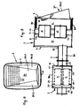
- the exhaust line consists of a multi-part exhaust line 1 with different Internals.
- the exhaust pipe 1 begins in the form of the cylinder head on the internal combustion engine flanged exhaust ducts that open into one or more exhaust manifolds and either directly or through exhaust manifolds on an exhaust gas turbine multi-stage exhaust gas turbocharger unit is or are connected. At the exhaust outlet this exhaust gas turbocharger unit is followed by an exhaust pipe section into which According to the invention, a front silencer 2 is installed in a main silencer 3 flows into.
- a device for separating and oxidizing very fine particles from the exhaust gas which consists of at least one oxidation catalyst 4 which significantly increases the NO 2 content of the nitrogen oxide in the exhaust gas and at least one filterless particle separator and oxidizer 5 downstream of the same.
- the main silencer 3 is, according to the invention, the outside through a front end wall 6, a rear end wall 7 and a peripheral wall 8 limited and inside by a gas-tight Partition 9 divided into an inflow chamber 10 and an outflow chamber 11.
- the at least one particle separator and -oxidator 5 installed in the main silencer 3, so that it one end with the inflow chamber 10 and the other end with the outflow chamber 11 communicated.
- a plurality of particle separation and oxidation modules are preferred 5 each provided in its own module housing 12, which are parallel to one another and arranged to the longitudinal axis of the main silencer 3 are installed in this and there from the intermediate wall 9 and possibly another, parallel to this, not gastight retaining wall 13 are held in a stable position in the installed position.
- the particle separation and oxidation module (s) 5 is further below discussed in more detail.
- the main silencer 3 has no tailpipes formed and has on its exhaust outlet end wall 7 and / or the exhaust outlet side End region of its peripheral wall 8 or one provided for exhaust gas outlet Area 14 of its end wall 6 on the exhaust gas inlet side one or more for a direct, Endless pipe outlet of the cleaned exhaust gas from the outflow chamber 11 into the Outlet opening (s) 15 designed in accordance with the atmosphere.
- the main silencer 3 is only on a partial sound absorption volume designed and the missing in the main silencer 3 Sound absorption volume is realized in the front silencer 2, which is spaced apart from the main silencer 3 is installed as close as possible to the engine in the exhaust pipe 1.
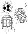
- the at least one oxidation catalyst 4 either in the front silencer 2 (see Fig. 1, 3, 5, 7, 9, 11, 13, 15, 17, 18) or installed before or after it in the exhaust pipe 1 (see FIG. 19).
- the front silencer 2 outside through a front, exhaust gas inlet side end wall 16, a parallel to this rear, exhaust outlet side end wall 17 and a cylindrical peripheral wall 18 limited.
- the interior of this roughly barrel-shaped front silencer 2 is gas-tight Partition 19 divided into an inflow chamber 20 and an outflow chamber 21.
- a connected to the exhaust gas inlet end wall 16 opens into the inflow chamber 20 Pipe socket 22, on which either one connected to the internal combustion engine Exhaust manifold or an exhaust manifold connected to the latter or the exhaust port of an exhaust gas turbine of a single or multi-stage exhaust gas turbocharger or a flue pipe section connected to the latter is flanged.
- the end wall 17 delimiting the outflow chamber 21 either goes directly or over a pipe socket 23 leading to the main silencer 2 exhaust pipe section 1/1 from.
- a packaged in a housing 24 can large-volume oxidation catalyst 4 (see, for example, FIG. 1) or more, each in a separate housing 24 packed small-volume oxidation catalysts 4 installed his. 3, 5, 9, 11, 13, 15 are two or four, in the case of the examples according to 7 and 17, 18, three oxidation catalysts 4 are installed in parallel flow.
- the oxidation catalyst (s) 4 in the interior of the pre-silencer 2 axially parallel to its longitudinal axis and to each other through the gas-tight partition 19 and - if necessary (as shown) - by another, not gas-tight, e.g. B. perforated Retaining wall 25 held stable in the installed position.
- the communicate Oxidation catalyst (s) 4 one end with the inflow chamber 20, the other end with the Outflow chamber 21 and its housing 24 are with the respective end face of the adjacent one End wall 16 and 17 of the front silencer 2 spaced to a certain extent.
- a plurality of oxidation catalysts packed in the housing 24 can be used 4 be installed in an exhaust pipe section 1/2, namely axially parallel to each other for parallel flow, but at an acute angle to the two Connection piece 26, 27 connecting longitudinal axis of the exhaust pipe section 1/2 standing.
- This has a correspondingly large between the two connecting pieces 26, 27 Installation space 28 for the oxidation catalysts 4, the internally by a gas-tight Partition 29 is divided into an inflow chamber 30 and an outflow chamber 31.
- the intermediate wall 29 and optionally a further, non-gas-tight holding wall 32 the oxidation catalysts 4 are held in a stable position in the installed position.
- the exhaust pipe section 1/2 is e.g. B. longitudinally divided into two half-shells, the installation allow the oxidation catalysts 4 and the walls 29, 32 and then are assembled gastight.
- main silencer 3 its two end walls 6, 7 are largely arranged flat and parallel to each other.
- the peripheral wall 8 is cylindrical. It there is thus an approximately barrel-shaped main silencer 2, in the interior of which the gas-tight Intermediate wall 9 and the holding wall 13, which may also be provided arranged parallel to the end walls 6, 7 and on the inside of the peripheral outer wall 8 attached, e.g. B. are welded.
- the exhaust pipe 1 opens into the inflow chamber 10 of the main silencer 3 with a Section 1/1, which is connected to a pipe socket 33 given in the end wall 6 is.
- the exhaust pipe 1 is set internally Main silencer 3 continues with a section 1/3, which there is the outflow chamber 11, the Partition 9 and the support wall 13 penetrates and behind the support wall 13 in the inflow chamber 10 opens.
- 1-2, 3-4, 5-6, 7-8 are either two or four, in the examples 9-10, 13-14, 17-18, 19-20 are four, in the case of the examples according to FIGS. 11-12 and 15-16 are five particle separator and oxidation modules 5 in the main silencer 3 installed.
- the main silencer is characterized 3 according to the invention in that it is either on its end wall on the exhaust gas outlet side 7 - see Fig. 1-2, 3-4, 5-6, 7-8 - and / or the exhaust outlet end region of it Circumferential wall 5 - see Fig. 1-2, 11-12, 13-14 - or one provided for exhaust gas outlet Area 14 of its end wall 6 on the exhaust gas inlet side - see FIGS. 9-10, 15-16 or more for a direct, exhaust pipe-free discharge of the cleaned exhaust gas into the atmosphere has appropriately designed outlet opening (s) 15.
- Each outlet opening 15 or a group of outlet openings 15 can have a flow guiding element 34 may be assigned to that from the outflow chamber 11 into the atmosphere escaping exhaust gas a certain direction or change of direction, eg. B. after embossed at the bottom or at an angle towards the back.
- each flow control element 34 can also be designed with a view to the flow through or by Exhaust gas can be impressed with a defined pressure release. The latter can realized by specially installed or provided guide walls or further deflection elements his.
- a plurality of outlet openings in the exhaust outlet side End wall 7 provided and each of these outlet openings 15 one in the manner of a scoop trained flow guide 34 assigned.
- the outlet openings are 15 and the associated scoops 34 in one piece with the front wall 7 of the main silencer 3 manufactured by punching and stamping.
- FIGS. 3-4 there are three outlet openings 15 in the end wall on the exhaust gas outlet side 7 of the main silencer 3 is provided, each of which by a type Cover designed flow guide element 34 is covered, the respective cover a Exhaust gas baffle 34/1 directed obliquely downwards towards the rear, which is in the lateral boundary walls 34/2, 34/3 merges and thus forms a kind of diffuser.
- outlet openings 15 in the upper half the exhaust outlet end wall 7 of the main silencer 3 is provided. These outlet openings 15 are placed on the outside of the end wall 4, in the manner of a Cover designed flow guide element 34 covers.
- This scoop shows one at an angle Exhaust gas guide wall 34/1, which is pulled down at the bottom, opens into the side walls 34/2, 34/3 passes. In terms of flow, this scoop forms a conically widening Diffuser.
- the end wall 7 of the main silencer on the exhaust gas outlet side 3 from at least two spaced apart from one another to a certain extent Partial walls 7/1, 7/2, the largest part of each of which forms the outlet openings 15 Holes is perforated.
- the outlet openings 15 are in the outer partial wall 7/2 arranged so that they are not arranged in the inner part wall 7/1 Outlet openings 15 are aligned. Rather, the outlet openings 15 are the inner partial wall 7/1 in its axial projection outside through a non-perforated wall area of the outer partial wall 7/2, which is given next to or between adjacent outlet openings 15 is covered.
- the exhaust gas emerging from the outflow chamber 11 arrives Flow through the outlet openings 15 of the inner partial wall 7/1 into the intermediate space between the two part walls 7/1, 7/2 and from there via the outlet openings 15 in the outer part wall 7/2 into the atmosphere. It would be conceivable to use this end wall 7/1, 7/2 Assign flow guide element 34 in the form of a scoop, which is formed like that according to FIGS. 5-6 could be.
- that lower region 14 of the end wall 6 on the exhaust gas inlet side is which covers a lower part chamber 11/2 of the outflow chamber 11, by a plurality of the holes forming the outlet openings 15 are perforated.
- the cleaned exhaust gas reaches a subspace 11/1 of the outflow chamber 11 and from there over the lower part 11/2, which has a diffuser-like cross section and through one or more longitudinal partition walls 35 is partitioned off from the inflow chamber 10, to the exhaust gas inlet end wall 6 and there in the area 14 via the outlet openings 15 into the atmosphere.
- FIGS. 11-12 is in the area of the outflow chamber 11 in the outer peripheral wall 8 an outlet opening 15 is provided, which is designed in the manner of a scoop and is associated with a diffuser-widening flow guide element 34. This extends from the end wall 7 in the direction of the end wall 6 completely or partially up to this.
- a further lateral outlet opening 15 is provided in the peripheral outer wall 8 be, which also a corresponding flow guide element 34 - as shown - would be assigned. This case is indicated by dashed lines in FIG. 12.
- a large part of the end wall 6 of the exhaust gas inlet is the Main muffler 3, which in these cases limits the outflow chamber 11 at the end a plurality of outlet openings 15, each one by a scoop formed flow guide element 34 is assigned.
- the outlet openings 15 and the scoops 34 in one piece with the end wall 6 by punching and stamping educated.
- the main silencer 3 is on the inside at least in the region of its outflow chamber 11, 11/1, 11/2 partially lined with sound absorbing material.
- the front silencer is also 2 at least partially on the inside at least in the area of its outflow chamber 28 lined with sound absorbing material. Such zones with sound absorbing Material is designated 36 in the drawing.
- the partial silencing volume given in the main silencer 3 is connected with the sound attenuation means 36 there and that given in the front silencer 2
- Partial sound attenuation volume in connection with the sound attenuation means there 36 designed in such a way that they add up to produce a total noise reduction effect which meets or falls below the statutory noise emission limits become.
- thermophoresis the carbon and / or condensed hydrocarbons existing fine particles in the particle separation and oxidation module (s) 5 deposited on the cooled surfaces.
- These can be internal to the module Surfaces by a gaseous or liquid coolant to a suitable one Temperature can be cooled down and z. B. on plates of a plate heat exchanger or cooled tubes of a shell and tube heat exchanger or the structure of a metallic Be given catalyst carrier body. This can also cool the surfaces are caused or supported that in the exhaust pipe 1 just before the main silencer 3 or in the inflow chamber 10, an aqueous solution is injected through Evaporation cooling the surfaces and thus increasing the thermophoresic Effect.
- thermophoresis The theory of thermophoresis is as follows: Hot exhaust gas flows along the cold surfaces. This forms in the exhaust gas stream a boundary layer in which the temperature is related in a certain way the exhaust gas further away from the cold surface falls off. The gas molecules move due to the lower temperature in the boundary layer, slower than in hotter ones Exhaust zones. If gas molecules hit a particle, they transfer one Impulse that is lower within the boundary layer than outside it. This results an asymmetrical impulse transmission to the particle, whereby this in the direction of the cold surfaces is moved until it hits there and because of the occurring Accumulate Von der der Walls forces. The influence of thermophoresis increases the smaller it is Particles are. Particles with a size or mass above 700 nm are therefore thermophoretic hardly separable anymore.
- the particle separation and oxidation module (s) are 5 internally formed with such structures and their surfaces so ribbed, knotted, corrugated or enlarged by other means that contained in the exhaust gas flowing past Particles are constantly forced to contact the surface and thereby adhere to the Deposit surfaces of the structures.
- a particularly high degree of separation is achieved if the module-internal structures are designed so that the direction of the exhaust gas flow constantly changing, e.g. B. must follow a zigzag course. As a result, that particles constantly encounter flow obstacles to which they attach.
- the particles separated in the particle separation and oxidation module (s) 5 by the abovementioned methods are catalytically oxidized or oxidized using the NO 2 present to a large extent in the exhaust gas and generated in the oxidation catalyst (s) 4 burned and convert to CO, CO 2 , N 2 , NO.
Landscapes
- Engineering & Computer Science (AREA)
- Chemical & Material Sciences (AREA)
- Combustion & Propulsion (AREA)
- Mechanical Engineering (AREA)
- General Engineering & Computer Science (AREA)
- Chemical Kinetics & Catalysis (AREA)
- Health & Medical Sciences (AREA)
- Biomedical Technology (AREA)
- Toxicology (AREA)
- Environmental & Geological Engineering (AREA)
- Analytical Chemistry (AREA)
- General Chemical & Material Sciences (AREA)
- Oil, Petroleum & Natural Gas (AREA)
- Exhaust Silencers (AREA)
- Exhaust Gas After Treatment (AREA)
- Processes For Solid Components From Exhaust (AREA)
Abstract
- einen Vorschalldämpfer (2) und einen Hauptschalldämpfer (3) in der Abgasleitung (1)
- eine Vorrichtung zur Abscheidung und Oxidation von Feinstpartikeln aus dem Abgas, bestehend aus wenigstens einem den NO2-Anteil des Stickoxids im Abgas signifikant erhöhenden Oxidationskatalysator (4) und stromab desselben wenigstens einem filterlosen Partikelabscheider und -oxidator (5),
- der Hauptschalldämpfer (3) ist außen durch eine vordere Stirnwand (6), eine hintere Stimwand (7) und eine Umfangswand (8) begrenzt sowie innen durch eine Wand (9) in eine Einströmkammer (10) und eine Ausströmkammer (11) unterteilt,
- der wenigstens ein Partikelabscheider und -oxidator ((5) ist in den Hauptschalldämpfer (3), dort einenendes mit der Einströmkammer (10), anderenendes mit der Ausströmkammer (11) kommunizierend, eingebaut,
- der Hauptschalldämpfer (3) ist endrohrlos ausgebildet und weist an seiner abgasaustrittsseitigen Stirnwand (7) und/oder dem abgasaustrittsseitigen Endbereich seiner Umfangsaußenwand (8) oder einem für Abgasauslass vorgesehenen Bereich (14) seiner abgaseintrittsseitigen Stirnwand (6) eine oder mehrere für einen direkten endrohrlosen Auslass des gereinigten Abgases aus der Ausströmkammer (11) in die Atmosphäre entsprechend gestaltete Auslassöffnungen (15) auf,
- der Hauptschalldämpfer (3) ist auf ein Teilschalldämpfungsvolumen ausgelegt und das im Hauptschalldämpfer (3) fehlende Schalldämpfungsvolumen ist im Vorschalldämpfer (2) realisiert, der beabstandet zum Hauptschalldämpfer (3) möglichst motornah in die Abgasleitung (1) eingebaut ist,
- der wenigstens eine Oxidationskatalysator (4) ist entweder in den Vorschalldämpfer (2) oder vor bzw. nach diesem in die Abgasleitung (1) eingebaut.
Description
- einen Vorschalldämpfer und einen Hauptschalldämpfer in der Abgasleitung,
- eine Vorrichtung zur Abscheidung und Oxidation von Feinstpartikeln aus dem Abgas, bestehend aus wenigstens einem den NO2-Anteil des Stickoxids im Abgas signifikant erhöhenden Oxidationskatalysator und stromab desselben wenigstens einem filterlosen Partikelabscheider und -oxidator,
- der Hauptschalldämpfer ist außen durch eine vordere Stirnwand, eine hintere Stirnwand und eine Umfangswand begrenzt sowie innen durch eine Wand in eine Einströmkammer und eine Ausströmkammer unterteilt,
- der wenigstens eine Partikelabscheider und -oxidator ist in den Hauptschalldämpfer, dort einenendes mit der Einströmkammer, anderenendes mit der Ausströmkammer kommunizierend, eingebaut,
- der Hauptschalldämpfer ist endrohrlos ausgebildet und weist an seiner abgasaustrittsseitigen Stirnwand und/oder dem abgasaustrittsseitigen Endbereich seiner Umfangsaußenwand oder einem für Abgasauslass vorgesehenen Bereich seiner abgasaustrittsseitigen Stirnwand eine oder mehrere für einen direkten endrohrlosen Auslass des gereinigten Abgases aus der Ausströmkammer in die Atmosphäre entsprechend gestaltete Auslassöffnungen auf,
- der Hauptschalldämpfer ist auf ein Teilschalldämpfungsvolumen ausgelegt und das im Hauptschalldämpfer fehlende Schalldämpfungsvolumen ist im Vorschalldämpfer realisiert, der beabstandet zum Hauptschalldämpfer möglichst motornah in die Abgasleitung eingebaut ist,
- der wenigstens eine Oxidationskatalysator ist entweder in den Vorschalldämpfer oder vor bzw. nach diesem in die Abgasleitung eingebaut.
Claims (31)
- Abgasstrang einer Brennkraftmaschine, insbesondere Dieselmotor eines Nutzfahrzeuges wie Lastkraftwagen oder Omnibus, mit integrierten Abgasnachbehandlungs- und Schalldämpfungsvorrichtungen, gekennzeichnet durch folgende Merkmale:einen Vorschalldämpfer (2) und einen Hauptschalldämpfer (3) in der Abgasleitung (1)eine Vorrichtung zur Abscheidung und Oxidation von Feinstpartikeln aus dem Abgas, bestehend aus wenigstens einem den NO2-Anteil des Stickoxids im Abgas signifikant erhöhenden Oxidationskatalysator (4) und stromab desselben wenigstens einem filterlosen Partikelabscheider und -oxidator (5),der Hauptschalldämpfer (3) ist außen durch eine vordere Stirnwand (6), eine hintere Stirnwand (7) und eine Umfangswand (8) begrenzt sowie innen durch eine Wand (9) in eine Einströmkammer (10) und eine Ausströmkammer (11) unterteilt,der wenigstens eine Partikelabscheider und -oxidator (5) ist in den Hauptschalldämpfer (3), dort einenendes mit der Einströmkammer (10), anderenendes mit der Ausströmkammer (11) kommunizierend, eingebaut,der Hauptschalldämpfer (3) ist endrohrlos ausgebildet und weist an seiner abgasaustrittsseitigen Stirnwand (7) und/oder dem abgasaustrittsseitigen Endbereich seiner Umfangsaußenwand (8) oder einem für Abgasauslass vorgesehenen Bereich (14) seiner abgaseintrittsseitigen Stirnwand (6) eine oder mehrere für einen direkten endrohrlosen Auslass des gereinigten Abgases aus der Ausströmkammer (11) in die Atmosphäre entsprechend gestaltete Auslassöffnungen (15) auf,der Hauptschalldämpfer (3) ist auf ein Teilschalldämpfungsvolumen ausgelegt und das im Hauptschalldämpfer (3) fehlende Schalldämpfungsvolumen ist im Vorschalldämpfer (2) realisiert, der beabstandet zum Hauptschalldämpfer (3) möglichst motornah in die Abgasleitung (1) eingebaut ist,der wenigstens eine Oxidationskatalysator (4) ist entweder in den Vorschalldämpfer (2) oder vor bzw. nach diesem in die Abgasleitung (1) eingebaut.
- Abgasstrang nach Anspruch 1, dadurch gekennzeichnet, dass der bzw. jeder der in den Innenraum des Hauptschalldämpfers (3) eingebaute(n) Partikelabscheide- und -oxidationsmodul(e) (5) mit seinem Gehäuse (12) achsparallel zur Längsmittelachse des Hauptschalldämpfers (3) verlaufend gasdicht in einer die Einströmkammer (10) zur Ausströmkammer (11) hin abschottenden Zwischenwand (9) und gegebenenfalls einer hierzu parallelen, nicht gasdichten Haltewand (13) befestigt ist, so, dass ein- und austrittsseitig ein größerer Abstand zur jeweils benachbarten Stirnwand (6, 7) gegeben ist.
- Abgasstrang nach Anspruch 1, dadurch gekennzeichnet, dass am Hauptschalldämpfer (3) jeder Auslassöffnung (15) oder einer Gruppe von Auslassöffnungen (15) ein dem aus der Ausströmkammer (11) austretenden Abgas eine bestimmte Richtung oder Richtungsänderung aufprägendes Strömungsleitelement (34) zugeordnet ist.
- Abgasstrang nach Anspruch 3, dadurch gekennzeichnet, dass am Hauptschalldämpfer (3) jedes Strömungsleitelement (34) auch im Hinblick darauf, dass dem durch- bzw. vorbeiströmenden Abgas eine definierte Druckentspannung aufprägbar ist, ausgebildet ist.
- Abgasstrang nach einem der Ansprüche 3 und 4, dadurch gekennzeichnet, dass am Hauptschalldämpfer (3) jeder Auslassöffnung (15) ein nach Art einer Hutze ausgebildetes Strömungsleitelement (34) zugeordnet ist.
- Abgasstrang nach Anspruch 5, dadurch gekennzeichnet, dass die Hutze(n) (34) einzeln hergestellt und dann außen an der die Auslassöffnungen (15) aufweisenden Stirnwand (6, 7) des Hauptschalldämpfers (3) befestigt ist bzw. sind.
- Abgasstrang nach einem der Ansprüche 5 und 6, dadurch gekennzeichnet, dass eine Hutze (34) durch ein Rohrbogensegment gebildet ist, dessen Umlenkwinkel - je nach dem Grad der gewünschten Abgasumlenkung nach unten - zwischen ca. 30° und 90° beträgt.
- Abgasstrang nach Anspruch 7, dadurch gekennzeichnet, dass in eine Hutze (34) wenigstens eine Leitwand eingebaut ist, die sich vorzugsweise parallel zur Umleitlinie erstreckt.
- Abgasstrang nach einem der Ansprüche 5 und 6, dadurch gekennzeichnet, dass die Hutze (34) eine schräg nach hinten unten gerichtete Abgasleitwand (34/1) aufweist, die in seitliche Begrenzungswände (34/2, 34/3) übergeht.
- Abgasstrang nach Anspruch 5, dadurch gekennzeichnet, dass die Auslassöffnungen (15) und die zugeordneten Hutzen (34) einstückig mit der betreffenden Stirnwand (6 bzw.7) des Hauptschalldämpfers (3) durch Ausstanzen und Ausprägen hergestellt sind.
- Abgasstrang nach einem der Ansprüche 3 und 4, dadurch gekennzeichnet, dass eine größere Anzahl von Auslassöffnungen (15) nur in einem bestimmten Bereich (14) einer Stirnwand (6 bzw. 7) des Hauptschalldämpfers (3), z. B. nur in deren oberer oder nur deren unterer Hälfte angeordnet ist, und dass diesen Auslassöffnungen (15) ein gemeinsames, nach Art einer Hutze ausgebildetes Strömungsleitelement (34) zugeordnet ist.
- Abgasstrang nach einem der Ansprüche 3 bis 11, dadurch gekennzeichnet, dass die bzw. jede Hutze (34) am Hauptschalldämpfer (3) einen sich in Ausströmrichtung trichterartig erweiternden Diffusor bildet.
- Abgasstrang nach Anspruch 1, dadurch gekennzeichnet, dass dann, wenn die Auslassöffnung(en) (15) in der Umfangswand (8) des Hauptschalldämpfers (3) gegeben ist bzw. sind, dieser bzw. diesen Auslassöffnung(en) (15) ein bzw. je ein oder ein gemeinsames nach Art einer Hutze gestaltetes Strömungsleitelement (34) zugeordnet ist, das sich von der einen Stirnwand (6 bzw. 7) zur bzw. in Richtung der anderen Stirnwand (7 bzw. 6) hin erstreckt und entweder Teilbereiche der Umfangsaußenwand (8) oder die gesamte Umfangswand (8) des Hauptschalldämpfers (3) überdeckt.
- Abgasstrang nach Anspruch 11, dadurch gekennzeichnet, dass die Ausströmkammer (11) in dem Fall, wenn die Auslassöffnung(en) (15) in einem Teilbereich (14) der abgaseintrittsseitigen Stirnwand (6) des Hauptschalldämpfers (3) gegeben sind, durch eine oder mehrere Längszwischenwände (35) zur Einströmkammer (10) hin abgeschottet ist und mit der solchermaßen begrenzten Teilkammer (11/2) zu der/den Auslassöffnung(en) (15) in der Stirnwand (6) hinreicht.
- Abgasstrang nach Anspruch 1, dadurch gekennzeichnet, dass in den Vorschalldämpfer (2) mehrere Oxidationskatalysatoren (4) mit ihren Gehäusen (24) achsparallel zu dessen Längsachse und zueinander eingebaut sind, derart, dass ein- bzw. austrittsseitig zur jeweils benachbarten Stirnwand (16, 17) des Vorschalldämpfers (2) ein bestimmter Abstand gegeben ist.
- Abgasstrang nach Anspruch 1, dadurch gekennzeichnet, dass mehrere Oxidationskatalysatoren (4) mit ihren Gehäusen (24) achsparallel durchströmbar in ein Abgasleitungsteilstück (1/2) eingebaut sind, und zwar mit ihren Längsachsen unter einem spitzen Winkel zur Längsachse des Abgasleitungsteilstücks (1/2), wobei dieses intern durch eine gasdichte Zwischenwand (29) in eine Einströmkammer (30) und eine Ausströmkammer (3) unterteilt ist.
- Abgasstrang nach Anspruch 15, dadurch gekennzeichnet, dass der Vorschalldämpfer (2) außen durch eine abgaseintrittsseitige Stirnwand (16), eine abgasaustrittsseitige Stirnwand (17) und eine Umfangswand (18) begrenzt ist, und dass der Innenraum des Vorschalldämpfers (2) durch eine gasdichte Zwischenwand (19) in eine Einströmkammer (20) und eine Ausströmkammer (21) unterteilt ist, wobei in die Einströmkammer (20) ein an der Stirnwand (16) angeschlossener Rohrstutzen (22) einmündet, an dem entweder eine Abgassammelleitung oder ein an letzterer angeschlossener Abgaskrümmer oder der Auslassstutzen einer Abgasturbine eines Abgasturboladeraggregates oder ein an letzterer angeschlossenes Abgasleitungsteilstück angeschlossen ist, und wobei die Oxidationskatalysatoren (4) durch die Zwischenwand (19) und gegebenenfalls eine weitere, nicht gasdichte Haltewand (25) lagestabil im Vorschalldämpfer-Innenraum gehaltert sind, und wobei von der die Ausströmkammer(21) begrenzenden Stirnwand (17) ein Rohrstutzen (23) oder ein zum Hauptschalldämpfer (3) hin führendes Abgasleitungsteilstück (1/1) abgeht.
- Abgasstrang nach Anspruch 1, dadurch gekennzeichnet, dass der Vorschalldämpfer (2) innen zumindest im Bereich seiner Ausströmkammer (21) wenigstens partiell mit schallabsorbierendem Material (36) ausgekleidet ist.
- Abgasstrang nach Anspruch 1, dadurch gekennzeichnet, dass der Hauptschalldämpfer (3) innen zumindest im Bereich der Ausströmkammer (11) wenigstens partiell mit schallabsorbierenden Material (36) ausgekleidet ist.
- Abgasstrang nach Anspruch 1 dadurch gekennzeichnet, dass die Schalldämpfungsmaßnahmen im endrohrlosen Hauptschalldämpfer (3) addiert zu den Schalldämpfungsmaßnahmen im Vorschalldämpfer (2) einen Gesamtschalldämpfungseffekt ergeben, der der Einhaltung gesetzlicher Schallemissionswerte gerecht wird.
- Abgasstrang nach einem der Ansprüche 1 und 2, dadurch gekennzeichnet, dass die im Abgas enthaltenden Feinstpartikel in den bzw. den Partikelabscheide- und -oxidationsmodul(en) (5) durch Thermophorese an gekühlten Oberflächen abscheidbar sind.
- Abgasstrang nach einem der Ansprüche 1 und 2, dadurch gekennzeichnet, dass die im Abgas enthaltenen Feinstpartikel in dem bzw. den Partikelabscheide- und -oxidationsmodul(en) (5) durch Konvektion an strukturierten Oberflächen und/oder aufgrund von wiederholtem Umlenken der Strömung abscheidbar sind.
- Abgasstrang nach einem der Ansprüche 1 und 2, dadurch gekennzeichnet, dass die im Abgas enthaltenen Feinstpartikel in dem bzw. den Partikelabscheide- und -oxidationsmodul(en) (5) durch Diffusion in Strömungstotzonen und/oder engen Strömungskanälen abscheidbar sind, wobei der kleinste freie Querschnitt der Strömungskanäle zwischen 25 µm2 und 250 µm2 liegt. 1
- Abgasstrang nach einem der Ansprüche 21 bis 23, dadurch gekennzeichnet, dass die im Abgas enthaltenen Feinstpartikel in dem bzw. den Partikelabscheide- und -oxidationsmodul(en) (5) durch eine Kombination aus Thermophorese, Konvektion und Diffusion abscheidbar sind.
- Abgasstrang nach den Ansprüchen 21 und 24, dadurch gekennzeichnet, dass im Fall der thermophoresischen Partikelabscheidung die intern des bzw. der Partikelabscheide- und -oxidationsmodule(s) (5) thermophoresisch wirksamen Oberflächen durch ein gasförmiges oder flüssiges Kühlmittel kühlbar sind.
- Abgasstrang nach Anspruch 25, dadurch gekennzeichnet, dass die kühlbaren Oberflächen an gekühlten Platten eines Plattenwärmetauschers oder gekühlten Rohren eines Rohrbündelwärmetauschers gegeben sind.
- Abgasstrang nach Anspruch 25, dadurch gekennzeichnet, dass die kühlbaren Oberflächen an der Struktur eines metallischen Katalysatorträgers gegeben sind.
- Abgasstrang nach einem der Ansprüche 25 bis 27, dadurch gekennzeichnet, dass in die Abgasleitung (1) kurz vor dem Hauptschalldämpfer (3) oder in dessen Einströmkammer (10) eine wässrige Lösung eindüsbar ist, die durch Verdunstung eine Abkühlung der Oberflächen mit Erhöhung der thermophoresischen Wirkung erbringt.
- Abgasstrang nach einem der Ansprüche 21 bis 28, dadurch gekennzeichnet, dass die Oberfläche der Struktur innerhalb des bzw. der Partikelabscheide- und -oxidationsmodule(s) (5) verrippt, vernoppt, gewellt oder durch sonstige Mittel vergrößert ist.
- Abgasstrang nach einem der Ansprüche 21 bis 28, dadurch gekennzeichnet, dass die Struktur innerhalb des bzw. der Partikelabscheide- und -oxidationsmodule(s) (5) derart ausgebildet ist, dass sich die Richtung der Abgasströmung ständig ändert, z. B. einem Zick-Zack-Kurs folgt.
- Abgasstrang nach einem der Ansprüche 21 bis 28, dadurch gekennzeichnet, dass intern des bzw. der Partikelabscheide- und -oxidationsmodule(s) (5) Strömungskanäle mit solcher Formgebung und speziellen Leitvorrichtungen gegeben sind, dass die Abgasströmung in Rotation versetzbar ist.
Applications Claiming Priority (2)
| Application Number | Priority Date | Filing Date | Title |
|---|---|---|---|
| DE10123358A DE10123358A1 (de) | 2001-05-14 | 2001-05-14 | Abgasstrang einer Brennkraftmaschine, insbesondere Dieselmotor eines Nutzfahrzeuges wie Lastkraftwagen oder Omnibus, mit integrierten Abgasnachbehandlungs- und Schalldämpfungsvorrichtungen |
| DE10123358 | 2001-05-14 |
Publications (2)
| Publication Number | Publication Date |
|---|---|
| EP1262640A1 true EP1262640A1 (de) | 2002-12-04 |
| EP1262640B1 EP1262640B1 (de) | 2004-03-03 |
Family
ID=7684702
Family Applications (1)
| Application Number | Title | Priority Date | Filing Date |
|---|---|---|---|
| EP02006845A Expired - Lifetime EP1262640B1 (de) | 2001-05-14 | 2002-03-26 | Abgasstrang einer Brennkraftmaschine, insbesondere Dieselmotor eines Nutzfahrzeuges wie Lastkraftwagen oder Omnibus, mit integrierten Abgasnachbehandlungs- und Schalldämpfungsvorrichtungen |
Country Status (3)
| Country | Link |
|---|---|
| EP (1) | EP1262640B1 (de) |
| AT (1) | ATE261056T1 (de) |
| DE (2) | DE10123358A1 (de) |
Cited By (1)
| Publication number | Priority date | Publication date | Assignee | Title |
|---|---|---|---|---|
| EP2194251A1 (de) * | 2008-12-05 | 2010-06-09 | Emitec Gesellschaft für Emissionstechnologie mbH | Selbsttragende Halterung für Katalysatorträgerkörper |
Families Citing this family (3)
| Publication number | Priority date | Publication date | Assignee | Title |
|---|---|---|---|---|
| DE102006055036B4 (de) † | 2006-11-22 | 2023-03-02 | Faurecia Emissions Control Technologies, Germany Gmbh | Mischelement sowie Abgasanlage für eine Verbrennungskraftmaschine |
| DE102008031874B4 (de) * | 2008-07-05 | 2015-12-17 | Man Truck & Bus Ag | Abgasreinigungsvorrichtung für eine Brennkraftmaschine eines Fahrzeuges, insbesondere eines Nutzfahrzeuges sowie Anordnung einer Abgasreinigungsvorrichtung |
| US9267417B2 (en) | 2013-10-31 | 2016-02-23 | Faurecia Emissions Control Technologies Usa, Llc | Diffuser plate |
Citations (4)
| Publication number | Priority date | Publication date | Assignee | Title |
|---|---|---|---|---|
| EP0484925A1 (de) * | 1990-11-07 | 1992-05-13 | Ebara Corporation | Schalldämpfer mit Katalysator |
| WO1992018226A1 (en) * | 1991-04-23 | 1992-10-29 | Donaldson Company, Inc. | Hydrocarbon fueled combustion filter |
| US6038854A (en) * | 1996-08-19 | 2000-03-21 | The Regents Of The University Of California | Plasma regenerated particulate trap and NOx reduction system |
| DE19934932A1 (de) * | 1999-07-26 | 2001-02-01 | Man Nutzfahrzeuge Ag | Verfahren und Vorrichtung zur Abscheidung von Feinstpartikeln aus dem Abgas von Brennkraftmaschinen |
Family Cites Families (2)
| Publication number | Priority date | Publication date | Assignee | Title |
|---|---|---|---|---|
| US2975854A (en) * | 1957-08-01 | 1961-03-21 | Continental Motors Corp | Exhaust mufflers |
| DE19952428A1 (de) * | 1999-10-30 | 2001-05-03 | Man Nutzfahrzeuge Ag | Verfahren und Vorrichtung zur kombinierten katalytischen NOx-Reduktion und Schalldämpfung von Abgas im Abgasstrang einer Brennkraftmaschine |
-
2001
- 2001-05-14 DE DE10123358A patent/DE10123358A1/de not_active Withdrawn
-
2002
- 2002-03-26 AT AT02006845T patent/ATE261056T1/de not_active IP Right Cessation
- 2002-03-26 DE DE50200268T patent/DE50200268D1/de not_active Expired - Fee Related
- 2002-03-26 EP EP02006845A patent/EP1262640B1/de not_active Expired - Lifetime
Patent Citations (4)
| Publication number | Priority date | Publication date | Assignee | Title |
|---|---|---|---|---|
| EP0484925A1 (de) * | 1990-11-07 | 1992-05-13 | Ebara Corporation | Schalldämpfer mit Katalysator |
| WO1992018226A1 (en) * | 1991-04-23 | 1992-10-29 | Donaldson Company, Inc. | Hydrocarbon fueled combustion filter |
| US6038854A (en) * | 1996-08-19 | 2000-03-21 | The Regents Of The University Of California | Plasma regenerated particulate trap and NOx reduction system |
| DE19934932A1 (de) * | 1999-07-26 | 2001-02-01 | Man Nutzfahrzeuge Ag | Verfahren und Vorrichtung zur Abscheidung von Feinstpartikeln aus dem Abgas von Brennkraftmaschinen |
Cited By (1)
| Publication number | Priority date | Publication date | Assignee | Title |
|---|---|---|---|---|
| EP2194251A1 (de) * | 2008-12-05 | 2010-06-09 | Emitec Gesellschaft für Emissionstechnologie mbH | Selbsttragende Halterung für Katalysatorträgerkörper |
Also Published As
| Publication number | Publication date |
|---|---|
| DE50200268D1 (de) | 2004-04-08 |
| ATE261056T1 (de) | 2004-03-15 |
| DE10123358A1 (de) | 2002-11-21 |
| EP1262640B1 (de) | 2004-03-03 |
Similar Documents
| Publication | Publication Date | Title |
|---|---|---|
| EP2691618B1 (de) | Kompakte abgasbehandlungseinheit mit mischbereich und verfahren zur vermischung eines abgases | |
| EP1728984B1 (de) | Abgasanlage | |
| DE112005002903B4 (de) | Abgasreinigungsvorrichtung für Brennkraftmaschine | |
| DE60122688T2 (de) | Schalldämpfer mit einem oder mehreren porösen körpern | |
| DE69704351T2 (de) | Schalldämpfer | |
| EP1866591B1 (de) | Abgaswärmeübertrager, insbesondere abgaskühler für abgasrückführung in kraftfahrzeugen | |
| EP0482307B1 (de) | Filter | |
| EP0676535A1 (de) | Katalysator für die katalytische Behandlung von Abgas | |
| EP1536113A2 (de) | Schalldämpfer mit integriertem Katalysator | |
| DE10329000A1 (de) | Abgasnachbehandlungsanlage mit einem Gegenstromgehäuse, sowie entsprechendes Verfahren zur Abgasnachbehandlung | |
| DE102014205782B4 (de) | Abgasreinigungsvorrichtung für Brennkraftmaschinen | |
| EP2823163B1 (de) | Abgasreinigungsvorrichtung | |
| EP1475522A2 (de) | Kombinierte Abgasnachbehandlungs-/Schalldämpfungsvorrichtung im Abgasstrang einer Brennkraftmaschine | |
| EP1304152B1 (de) | Abgasanlage mit Partikelfilter für einen Verbrennungsmotor | |
| EP1262640B1 (de) | Abgasstrang einer Brennkraftmaschine, insbesondere Dieselmotor eines Nutzfahrzeuges wie Lastkraftwagen oder Omnibus, mit integrierten Abgasnachbehandlungs- und Schalldämpfungsvorrichtungen | |
| EP2194251B1 (de) | Selbsttragende Halterung für Katalysatorträgerkörper | |
| DE1293792B (de) | Vorrichtung zur Nachverbrennung des Abgases von Brennkraftmaschinen | |
| DE3319529A1 (de) | Auspuffanlage | |
| EP1882090B1 (de) | Abgasanlage mit zwei abgasbehandlungseinheiten | |
| DE60214748T2 (de) | In einem abgassystem für einen verbrennungsmotor angeordnetes gehäuse | |
| EP0442318A2 (de) | Durch Abbrennen regenerierbarer Partikelfilter für die Abgase von Brennkraftmaschinen | |
| EP1486649B1 (de) | Katalysator und Verfahren zu dessen Herstellung | |
| EP3759327B1 (de) | Vorrichtung zur abgasnachbehandlung | |
| EP2740913A1 (de) | Abgasnachbehandlungssystem | |
| DE102013022009A1 (de) | Vorrichtung zur Nachbehandlung von Abgasen eines Verbrennungsmotors |
Legal Events
| Date | Code | Title | Description |
|---|---|---|---|
| PUAI | Public reference made under article 153(3) epc to a published international application that has entered the european phase |
Free format text: ORIGINAL CODE: 0009012 |
|
| 17P | Request for examination filed |
Effective date: 20020928 |
|
| AK | Designated contracting states |
Kind code of ref document: A1 Designated state(s): AT BE CH CY DE DK ES FI FR GB GR IE IT LI LU MC NL PT SE TR |
|
| AX | Request for extension of the european patent |
Free format text: AL;LT;LV;MK;RO;SI |
|
| RTI1 | Title (correction) |
Free format text: EXHAUST LINE OF AN INTERNAL ENGINE, ESPECIALLY DIESEL ENGINE FROM UTILITY VEHICULES SUCH AS TRUCKS OR BUSES, WITH AN INTEGRATED DEVICE FOR TREATING AN EXHAUST GAS AN ATTENUATE NOISE |
|
| AKX | Designation fees paid |
Designated state(s): AT DE FR IT NL SE |
|
| GRAP | Despatch of communication of intention to grant a patent |
Free format text: ORIGINAL CODE: EPIDOSNIGR1 |
|
| GRAS | Grant fee paid |
Free format text: ORIGINAL CODE: EPIDOSNIGR3 |
|
| GRAA | (expected) grant |
Free format text: ORIGINAL CODE: 0009210 |
|
| AK | Designated contracting states |
Kind code of ref document: B1 Designated state(s): AT DE FR IT NL SE |
|
| REG | Reference to a national code |
Ref country code: IE Ref legal event code: FG4D Free format text: GERMAN |
|
| REF | Corresponds to: |
Ref document number: 50200268 Country of ref document: DE Date of ref document: 20040408 Kind code of ref document: P |
|
| REG | Reference to a national code |
Ref country code: SE Ref legal event code: TRGR |
|
| REG | Reference to a national code |
Ref country code: IE Ref legal event code: FD4D |
|
| ET | Fr: translation filed | ||
| PLBE | No opposition filed within time limit |
Free format text: ORIGINAL CODE: 0009261 |
|
| STAA | Information on the status of an ep patent application or granted ep patent |
Free format text: STATUS: NO OPPOSITION FILED WITHIN TIME LIMIT |
|
| 26N | No opposition filed |
Effective date: 20041206 |
|
| PGFP | Annual fee paid to national office [announced via postgrant information from national office to epo] |
Ref country code: DE Payment date: 20090320 Year of fee payment: 8 Ref country code: IT Payment date: 20090321 Year of fee payment: 8 |
|
| PGFP | Annual fee paid to national office [announced via postgrant information from national office to epo] |
Ref country code: FR Payment date: 20090312 Year of fee payment: 8 |
|
| PGFP | Annual fee paid to national office [announced via postgrant information from national office to epo] |
Ref country code: AT Payment date: 20100311 Year of fee payment: 9 |
|
| PGFP | Annual fee paid to national office [announced via postgrant information from national office to epo] |
Ref country code: NL Payment date: 20100315 Year of fee payment: 9 |
|
| PGFP | Annual fee paid to national office [announced via postgrant information from national office to epo] |
Ref country code: SE Payment date: 20100312 Year of fee payment: 9 |
|
| REG | Reference to a national code |
Ref country code: FR Ref legal event code: ST Effective date: 20101130 |
|
| PG25 | Lapsed in a contracting state [announced via postgrant information from national office to epo] |
Ref country code: FR Free format text: LAPSE BECAUSE OF NON-PAYMENT OF DUE FEES Effective date: 20100331 |
|
| PG25 | Lapsed in a contracting state [announced via postgrant information from national office to epo] |
Ref country code: DE Free format text: LAPSE BECAUSE OF NON-PAYMENT OF DUE FEES Effective date: 20101001 |
|
| PG25 | Lapsed in a contracting state [announced via postgrant information from national office to epo] |
Ref country code: IT Free format text: LAPSE BECAUSE OF NON-PAYMENT OF DUE FEES Effective date: 20100326 |
|
| REG | Reference to a national code |
Ref country code: NL Ref legal event code: V1 Effective date: 20111001 |
|
| REG | Reference to a national code |
Ref country code: SE Ref legal event code: EUG |
|
| PG25 | Lapsed in a contracting state [announced via postgrant information from national office to epo] |
Ref country code: AT Free format text: LAPSE BECAUSE OF NON-PAYMENT OF DUE FEES Effective date: 20110326 |
|
| PG25 | Lapsed in a contracting state [announced via postgrant information from national office to epo] |
Ref country code: NL Free format text: LAPSE BECAUSE OF NON-PAYMENT OF DUE FEES Effective date: 20111001 |
|
| PG25 | Lapsed in a contracting state [announced via postgrant information from national office to epo] |
Ref country code: SE Free format text: LAPSE BECAUSE OF NON-PAYMENT OF DUE FEES Effective date: 20110327 |