EP1262308A2 - Procédé de fabrication d'un composant optique, moule pour la mise en oeuvre de ce procédé et composant optique obtenu par ce procédé - Google Patents
Procédé de fabrication d'un composant optique, moule pour la mise en oeuvre de ce procédé et composant optique obtenu par ce procédé Download PDFInfo
- Publication number
- EP1262308A2 EP1262308A2 EP02291291A EP02291291A EP1262308A2 EP 1262308 A2 EP1262308 A2 EP 1262308A2 EP 02291291 A EP02291291 A EP 02291291A EP 02291291 A EP02291291 A EP 02291291A EP 1262308 A2 EP1262308 A2 EP 1262308A2
- Authority
- EP
- European Patent Office
- Prior art keywords
- mold
- active
- optical component
- neutral
- complementary
- Prior art date
- Legal status (The legal status is an assumption and is not a legal conclusion. Google has not performed a legal analysis and makes no representation as to the accuracy of the status listed.)
- Granted
Links
Images

Classifications
-
- F—MECHANICAL ENGINEERING; LIGHTING; HEATING; WEAPONS; BLASTING
- F21—LIGHTING
- F21V—FUNCTIONAL FEATURES OR DETAILS OF LIGHTING DEVICES OR SYSTEMS THEREOF; STRUCTURAL COMBINATIONS OF LIGHTING DEVICES WITH OTHER ARTICLES, NOT OTHERWISE PROVIDED FOR
- F21V5/00—Refractors for light sources
- F21V5/04—Refractors for light sources of lens shape
- F21V5/045—Refractors for light sources of lens shape the lens having discontinuous faces, e.g. Fresnel lenses
-
- B—PERFORMING OPERATIONS; TRANSPORTING
- B29—WORKING OF PLASTICS; WORKING OF SUBSTANCES IN A PLASTIC STATE IN GENERAL
- B29D—PRODUCING PARTICULAR ARTICLES FROM PLASTICS OR FROM SUBSTANCES IN A PLASTIC STATE
- B29D11/00—Producing optical elements, e.g. lenses or prisms
- B29D11/00009—Production of simple or compound lenses
- B29D11/00269—Fresnel lenses
-
- F—MECHANICAL ENGINEERING; LIGHTING; HEATING; WEAPONS; BLASTING
- F21—LIGHTING
- F21S—NON-PORTABLE LIGHTING DEVICES; SYSTEMS THEREOF; VEHICLE LIGHTING DEVICES SPECIALLY ADAPTED FOR VEHICLE EXTERIORS
- F21S41/00—Illuminating devices specially adapted for vehicle exteriors, e.g. headlamps
- F21S41/30—Illuminating devices specially adapted for vehicle exteriors, e.g. headlamps characterised by reflectors
- F21S41/32—Optical layout thereof
- F21S41/33—Multi-surface reflectors, e.g. reflectors with facets or reflectors with portions of different curvature
- F21S41/337—Multi-surface reflectors, e.g. reflectors with facets or reflectors with portions of different curvature the reflector having a structured surface, e.g. with facets or corrugations
-
- B—PERFORMING OPERATIONS; TRANSPORTING
- B29—WORKING OF PLASTICS; WORKING OF SUBSTANCES IN A PLASTIC STATE IN GENERAL
- B29L—INDEXING SCHEME ASSOCIATED WITH SUBCLASS B29C, RELATING TO PARTICULAR ARTICLES
- B29L2011/00—Optical elements, e.g. lenses, prisms
- B29L2011/0016—Lenses
- B29L2011/005—Fresnel lenses
-
- Y—GENERAL TAGGING OF NEW TECHNOLOGICAL DEVELOPMENTS; GENERAL TAGGING OF CROSS-SECTIONAL TECHNOLOGIES SPANNING OVER SEVERAL SECTIONS OF THE IPC; TECHNICAL SUBJECTS COVERED BY FORMER USPC CROSS-REFERENCE ART COLLECTIONS [XRACs] AND DIGESTS
- Y10—TECHNICAL SUBJECTS COVERED BY FORMER USPC
- Y10S—TECHNICAL SUBJECTS COVERED BY FORMER USPC CROSS-REFERENCE ART COLLECTIONS [XRACs] AND DIGESTS
- Y10S425/00—Plastic article or earthenware shaping or treating: apparatus
- Y10S425/808—Lens mold
Definitions
- the present invention relates to optical components in general, and more particularly such components comprising discontinuous surfaces, so as to form by example of Fresnel or stepped lenses or prisms. It also concerns a process for manufacturing such optical components.
- Such optical components are generally obtained by molding a material plastic or thermoplastic such as polymethyl methacrylate (PMMA) in a mold.
- the mold may include different parts determined by the complexity of the shape of the optical component to be obtained.
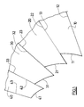
- FIG. 1 shows a part of a mold intended for molding components. with discontinuous surface.
- a mold comprises, in a known manner, inserts such as 10, 20, 30, 40, formed by blades machined with very high precision, imposed as well by the shape of the component to be molded, determined by their surfaces 11, 21, 31 respectively forming in the mold cavity proper the active surfaces of the optical component, only by their faces 12, 13, 22, 23, 32, 33, 42, 43 intended to come into mutual contact and to form neutral surfaces of the optical component.
- Each blade corresponds to one of the discontinuities of the optical component to be produced.
- the active surface of the component is called optical a surface participating in the development of a light beam, and through which pass light rays from a source, and the neutral surface of the optical component a surface without effect on the development of the light beam, and through which no light ray passes.
- the blades are machined, then assembled and held together to form the walls of the desired mold, complementary to the surfaces of the optical component to be produced. Their assembly also requires great precision if you want the molded component has the required optical qualities. As a result, such a mold is relatively difficult to obtain by the precision of the blades requested, by the precision of the adjustment of the blades between them and by general maintenance of the mold.
- the present invention is placed in this context and its aim is to propose a method molding of optical components, according to which the mold is easier to obtain and to maintain, less expensive, the optical components thus molded having the optical qualities required.
- the step of forming the complementary mold surfaces active and neutral surfaces of the optical component is produced by continuous cutting of a block of material using a cutting tool.
- the present invention also aims to provide a mold for component optic having active surfaces separated by neutral surfaces forming discontinuities between surfaces, comprising surfaces complementary to the active surfaces and neutrals of the optical component, characterized in that it includes a depression in a first mold surface complementary to a neutral surface of the component in the vicinity a second surface of the mold complementary to an active surface of the component, the first and second mold surfaces forming an obtuse angle between them.
- the present invention also aims to provide an optical component having active surfaces separated by neutral surfaces forming discontinuities between active surfaces, characterized in that the neutral surfaces have an appendix to their end making an acute angle with an active surface.
- the component optics is made of polymethyl methacrylate.
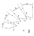
- FIG. 2 shows the optical component C obtained using the mold of the Figure 1, as well as the light beams formed by this component.
- the component optic C has active surfaces 14, 24, 34, 44, complementary to the faces 11, 21, 31, 41 of the blades 10, 20, 30, 40 described above, and of the neutral surfaces 25, 35, 45 formed by the faces 22, 32, 42 of the blades 20, 30, 40.
- the light rays coming from a source pass through the active surfaces 14, 24, 34, 44 of component C to form bundles 16, 26, 36, 46, while the surfaces 25, 35, 45 do not participate in the development of these light beams.
- the active surfaces 14, 24, 34, 44 are separated by the neutral surfaces 25, 35, 45 forming discontinuities between the active surfaces.
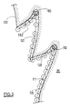
- FIG. 3 shows the method of forming the surfaces of the mold.
- part of a block of material for example steel or brass
- a tool cutting 50 delimiting the outline of this block of material, represented in several positions by its section in Figure 3.
- Figure 3 We have only shown in Figure 3 the part M of the block of material intended to form the final mold, the other part having been omitted for more clarity.
- the cutting tool 50 may consist of a wire 50, for example a tungsten wire stretched between two supports so as to remain rectilinear. Wire 50 is guided in the block of steel or brass along a curvilinear trajectory perpendicular to the axis of the wire while being traversed by an electric current.
- the wire 50 is guided with precision so as to form by EDM the surfaces 111, 121, 131 of the mold complementary to the active surfaces of the optical component to be produced, as well as the surfaces 122, 132 of the mold complementary to the neutral surfaces of the optical component. According to this process, it is easy to produce in the mold acute angles, for example between surfaces 122 and 121, or between surfaces 132 and 131.
- the realization in the mold of obtuse angles is limited by the diameter of the wire 50. It is thus possible to produce obtuse angles in the mold having a rounded apex, the radius of curvature is a function of the diameter of the cutting wire. For example, with 0.1 wire mm in diameter, it will be possible to obtain a radius of 0.06 mm.
- the obtuse angles of the mold are complementary acute angles of the optical component to be produced, for example between the surfaces 14 and 25, 24 and 35, 34 and 45. If it is important to produce the active surfaces 14 with precision, 24, 34 over their entire length, since they participate in the development of the beams 16, 26, 36, 46, the precision of realization of the neutral surfaces 25, 35, 45 has no effect on the behavior component finally obtained since they are located in areas of shadow between two beams.
- This property is used according to the present invention to produce the angles obtuse from the mold.
- the wire 50 creates a depression 60 in the adjacent surface 122, in the vicinity of the junction between these two surfaces of the mold M.
- this depression 60 will be shallow, and will correspond to a round trip of the tool cutting, in this case the wire 50. It will thus have a depth close to the diameter of the wire 50.
- EDM tungsten wires of larger diameter, and therefore more resistant and less expensive wires. We can for example use wires of 0.25 mm in diameter.
- FIG. 4 shows the optical component C obtained by molding in the mold produced according to Figure 3.
- the active surfaces of the component 111 and 121 are separated by a neutral surface 122, the latter comprising an appendage 160 complementary to depression 60, appendix 160 being located at the end of the surface neutral making an acute angle with the adjacent active surface 114.
- the active surface 114 transmits the light beam 116, and the active surface 124 transmits the light beam 126, the two light beams 124 and 126 being separated by a shaded area 70. It can be seen that appendix 160 extends into the shaded area 70, and does not does not interfere with the beams 116 or 126.
- the mold is made of a single block, and does not require precise adjustment of patches.
- the mold cutting operation is carried out in a single pass, whatever the number of teeth or active surfaces of the final optical component. Cutting wires 0.25 mm in diameter can be commonly used.
- Optical components molded to this process having the required optical qualities.
Landscapes
- Engineering & Computer Science (AREA)
- General Engineering & Computer Science (AREA)
- Health & Medical Sciences (AREA)
- Manufacturing & Machinery (AREA)
- Ophthalmology & Optometry (AREA)
- Mechanical Engineering (AREA)
- Moulds For Moulding Plastics Or The Like (AREA)
- Electrical Discharge Machining, Electrochemical Machining, And Combined Machining (AREA)
- Surface Treatment Of Glass (AREA)
- Casting Or Compression Moulding Of Plastics Or The Like (AREA)
- Eyeglasses (AREA)
Abstract
- former dans un moule (M) des surfaces complémentaires (111,121;122,132) des surfaces actives et neutres (114,124;125,135) du composant optique (C);
- mouler le composant optique (C) sur les surfaces du moule (M).
Description
- former dans un moule des surfaces complémentaires des surfaces actives et neutres du composant optique ;
- mouler le composant optique sur les surfaces du moule.
- le procédé comporte en outre l'étape consistant à creuser une dépression dans une première surface du moule complémentaire d'une surface neutre du composant au voisinage d'une deuxième surface du moule complémentaire d'une surface active du composant, les première et deuxième surfaces du moule faisant entre elles un angle obtus.
- la dépression a une profondeur voisine du diamètre de l'outil de découpe.
- la découpe continue est réalisée par électroérosion.
- la découpe continue est réalisée par un rayonnement laser.
- le bloc de matière est un bloc d'acier ou de laiton.
- La Figure 1 déjà décrite représente un moule pour composants optiques de l'art antérieur ;
- La Figure 2 représente en coupe partielle un composant optique obtenu avec le moule de la Figure 1 ;
- La Figure 3 représente les étapes du procédé de formation des surfaces du moule selon la présente invention, et
- La Figure 4 représente en coupe partielle un composant optique obtenu avec le moule selon la présente invention.
Claims (9)
- Procédé de fabrication d'un composant optique (C) possédant des surfaces actives (114, 124) séparées par des surfaces neutres (125, 135) formant des discontinuités entre les surfaces actives (114, 124), les surfaces actives (114, 124) et les surfaces neutres (125, 135) faisant entre elles des angles successivement aigus et obtus, le procédé comprenant les étapes consistant à :caractérisé en ce que l'étape de formation des surfaces (111, 121 ; 122, 132) du moule complémentaires des surfaces actives et neutres (114, 124 ; 125, 135) du composant optique (C) est réalisée par découpe continue d'un bloc de matière à l'aide d'un outil de découpe (50).former dans un moule (M) des surfaces complémentaires (111, 121 ; 122, 132) des surfaces actives et neutres (114, 124 ; 125, 135) du composant optique (C) ;mouler le composant optique (C) sur les surfaces du moule (M),
- Procédé selon la revendication 1, caractérisé en ce qu'il comporte en outre l'étape consistant à creuser une dépression (60) dans une première surface (122, 132) du moule complémentaire d'une surface neutre (125, 135) du composant (C) au voisinage d'une deuxième surface (111, 121) du moule complémentaire d'une surface active (114, 124) du composant (C), les première et deuxième surfaces du moule faisant entre elles un angle obtus.
- Procédé selon la revendication 2, caractérisé en ce que la dépression (60) a une profondeur voisine du diamètre de l'outil de découpe (50)
- Procédé selon la revendication 1, caractérisé en ce que la découpe continue est réalisée par électroérosion.
- Procédé selon la revendication 1, caractérisé en ce que la découpe continue est réalisée par un rayonnement laser.
- Procédé selon la revendication 1, caractérisé en ce que en ce que le bloc de matière est un bloc d'acier ou de laiton.
- Moule pour composant optique (C) possédant des surfaces actives (114, 124) séparées par des surfaces neutres (125, 135) formant des discontinuités entre les surfaces actives (114, 124), les surfaces actives (114, 124) et les surfaces neutres (125, 135) du composant optique (C) faisant entre elles des angles successivement aigus et obtus, le moule (M) comportant des surfaces complémentaires (111, 121 ; 122, 132) des surfaces actives et neutres (114, 124 ; 125, 135) du composant optique (C), caractérisé en ce qu'il comporte une dépression (60) dans une première surface (122, 132) du moule complémentaire d'une surface neutre (125, 135) du composant (C) au voisinage d'une deuxième surface (111, 121) du moule complémentaire d'une surface active (114, 124) du composant (C), les première et deuxième surfaces du moule faisant entre elles un angle obtus.
- Composant optique (C) possédant des surfaces actives (114, 124) séparées par des surfaces neutres (125, 135) formant des discontinuités entre les surfaces actives (114, 124), les surfaces actives (114, 124) et les surfaces neutres (125, 135) faisant entre elles des angles successivement aigus et obtus, caractérisé en ce que les surfaces neutres (125, 135) comportent un appendice (160) à leur extrémité faisant un angle aigu avec une surface active (114, 124).
- Composant optique (C) selon la revendication 8, caractérisé en ce qu'il est réalisé en polyméthylmatacrylate.
Applications Claiming Priority (2)
| Application Number | Priority Date | Filing Date | Title |
|---|---|---|---|
| FR0107109 | 2001-05-28 | ||
| FR0107109A FR2825045B1 (fr) | 2001-05-28 | 2001-05-28 | Procede de fabrication d'un composant optique, moule pour la mise en oeuvre de ce procede et composant optique obtenu par ce procede |
Publications (3)
| Publication Number | Publication Date |
|---|---|
| EP1262308A2 true EP1262308A2 (fr) | 2002-12-04 |
| EP1262308A3 EP1262308A3 (fr) | 2003-04-09 |
| EP1262308B1 EP1262308B1 (fr) | 2007-06-20 |
Family
ID=8863794
Family Applications (1)
| Application Number | Title | Priority Date | Filing Date |
|---|---|---|---|
| EP02291291A Expired - Lifetime EP1262308B1 (fr) | 2001-05-28 | 2002-05-27 | Procédé de fabrication d'un composant optique, moule pour la mise en oeuvre de ce procédé et composant optique obtenu par ce procédé |
Country Status (7)
| Country | Link |
|---|---|
| US (1) | US7083746B2 (fr) |
| EP (1) | EP1262308B1 (fr) |
| JP (1) | JP2003098320A (fr) |
| AT (1) | ATE365100T1 (fr) |
| DE (1) | DE60220743T2 (fr) |
| ES (1) | ES2289063T3 (fr) |
| FR (1) | FR2825045B1 (fr) |
Cited By (1)
| Publication number | Priority date | Publication date | Assignee | Title |
|---|---|---|---|---|
| FR2994248A1 (fr) * | 2012-08-02 | 2014-02-07 | Valeo Vision | Dispositif d'eclairage et/ou de signalisation d'un vehicule automobile |
Families Citing this family (1)
| Publication number | Priority date | Publication date | Assignee | Title |
|---|---|---|---|---|
| WO2004057585A1 (fr) | 2002-12-20 | 2004-07-08 | Mitsubishi Chemical Corporation | Support d'enregistrement optique, procede d'enregistrement du support d'enregistrement optique et enregistreur |
Family Cites Families (6)
| Publication number | Priority date | Publication date | Assignee | Title |
|---|---|---|---|---|
| JPS5617229A (en) * | 1979-07-20 | 1981-02-19 | Dainippon Printing Co Ltd | Method and apparatus for producing uniaxial fresnel lens |
| DE3330320A1 (de) * | 1983-08-23 | 1985-03-07 | Knut Otto 6580 Idar-Oberstein Saßmannshausen | Scheinwerfer, insbesondere fuer fahrraeder |
| JP2610029B2 (ja) * | 1987-12-28 | 1997-05-14 | ソニー株式会社 | 成形型の製造方法 |
| EP0844056B1 (fr) * | 1995-07-28 | 2003-04-09 | Nippon Carbide Kogyo Kabushiki Kaisha | Matrice microprisme |
| JP3531460B2 (ja) | 1998-03-19 | 2004-05-31 | 松下電器産業株式会社 | 磁気記録再生装置 |
| EP1055869A3 (fr) * | 1999-05-28 | 2002-03-06 | Corning Incorporated | Lentille en verre pour véhicule automobile |
-
2001
- 2001-05-28 FR FR0107109A patent/FR2825045B1/fr not_active Expired - Fee Related
-
2002
- 2002-05-22 US US10/154,103 patent/US7083746B2/en not_active Expired - Lifetime
- 2002-05-27 ES ES02291291T patent/ES2289063T3/es not_active Expired - Lifetime
- 2002-05-27 AT AT02291291T patent/ATE365100T1/de not_active IP Right Cessation
- 2002-05-27 DE DE60220743T patent/DE60220743T2/de not_active Expired - Lifetime
- 2002-05-27 EP EP02291291A patent/EP1262308B1/fr not_active Expired - Lifetime
- 2002-05-28 JP JP2002154098A patent/JP2003098320A/ja active Pending
Cited By (1)
| Publication number | Priority date | Publication date | Assignee | Title |
|---|---|---|---|---|
| FR2994248A1 (fr) * | 2012-08-02 | 2014-02-07 | Valeo Vision | Dispositif d'eclairage et/ou de signalisation d'un vehicule automobile |
Also Published As
| Publication number | Publication date |
|---|---|
| EP1262308B1 (fr) | 2007-06-20 |
| ES2289063T3 (es) | 2008-02-01 |
| US7083746B2 (en) | 2006-08-01 |
| DE60220743T2 (de) | 2008-04-10 |
| ATE365100T1 (de) | 2007-07-15 |
| FR2825045A1 (fr) | 2002-11-29 |
| US20020175429A1 (en) | 2002-11-28 |
| JP2003098320A (ja) | 2003-04-03 |
| FR2825045B1 (fr) | 2003-12-12 |
| EP1262308A3 (fr) | 2003-04-09 |
| DE60220743D1 (de) | 2007-08-02 |
Similar Documents
| Publication | Publication Date | Title |
|---|---|---|
| EP1030419B1 (fr) | Source laser à cavité externe accordable en longueur d'onde | |
| FR3087954A1 (fr) | Guide d'onde obtenu par fabrication additive | |
| EP3845802B1 (fr) | Boitier de connexion comprenant un coupleur optique surmoulé | |
| FR2775355A1 (fr) | Reflecteur optique en semi-conducteur et procede de fabrication | |
| EP1987932A1 (fr) | Procédé de fabrication de moules pour pneumatique cloute | |
| CA2493801A1 (fr) | Procede de realisation d'un outil destine au formage d'une matiere et outil susceptible d'etre realise par ce procede | |
| EP1262308B1 (fr) | Procédé de fabrication d'un composant optique, moule pour la mise en oeuvre de ce procédé et composant optique obtenu par ce procédé | |
| FR2763666A1 (fr) | Projecteur de vehicule automobile a miroir generateur de faisceau large et a glace striee | |
| FR2660716A1 (fr) | Piece de moyeu pour un disque d'embrayage et procede de fabrication de celle-ci. | |
| EP0014107B1 (fr) | Procédé de fabrication d'une douille cylindrique munie de rainures intérieures fermées à l'une au moins de leurs extrémités et douille ainsi obtenue | |
| FR2799153A1 (fr) | Procede de fabrication d'une lentille pour projecteur du genre elliptique de vehicule automobile, et projecteur incorporant une lentille perfectionnee | |
| EP3382270A1 (fr) | Guide de lumiere courbe propagateur de rayons lumineux | |
| EP3513230A1 (fr) | Dispositif de couplage optique | |
| CA2449005A1 (fr) | Procede de fabrication de profiles metalliques | |
| EP0943946A1 (fr) | Procédé de fabrication d'un multiruban de fibres optiques séparable en au moins deux rubans de fibres optiques | |
| EP0467746B1 (fr) | Procédé de réalisation de composants optiques intégrés | |
| EP0963865B1 (fr) | Procédé de réalisation d'un triangle de suspension métallique, triangle obtenu par le procédé et moule de mise en oeuvre de procédé | |
| CH717145A2 (fr) | Procédé de fabrication d'une pièce mécanique d'horlogerie monobloc. | |
| EP0860230B1 (fr) | Dispositif d'usinage laser, notamment pour l'usinage de bielles | |
| EP1558952A2 (fr) | Diviseur optique 2 vers n en optique integree | |
| FR2514072A1 (fr) | Procede de fabrication d'une aube pour moteur a turbine a gaz | |
| EP4300214A1 (fr) | Procede de fabrication d'une aiguille d'horlogerie de section circulaire | |
| CH719840A2 (fr) | Procédé de fabrication d'une aiguille d'horlogerie de section circulaire. | |
| CH712016A2 (fr) | Procédé de fabrication d'un élément optique pour pièce d'horlogerie. | |
| EP3865955A1 (fr) | Procédé de fabrication d'une pièce mécanique d'horlogerie monobloc |
Legal Events
| Date | Code | Title | Description |
|---|---|---|---|
| PUAI | Public reference made under article 153(3) epc to a published international application that has entered the european phase |
Free format text: ORIGINAL CODE: 0009012 |
|
| AK | Designated contracting states |
Kind code of ref document: A2 Designated state(s): AT BE CH CY DE DK ES FI FR GB GR IE IT LI LU MC NL PT SE TR |
|
| AX | Request for extension of the european patent |
Free format text: AL;LT;LV;MK;RO;SI |
|
| PUAL | Search report despatched |
Free format text: ORIGINAL CODE: 0009013 |
|
| AK | Designated contracting states |
Kind code of ref document: A3 Designated state(s): AT BE CH CY DE DK ES FI FR GB GR IE IT LI LU MC NL PT SE TR |
|
| AX | Request for extension of the european patent |
Extension state: AL LT LV MK RO SI |
|
| 17P | Request for examination filed |
Effective date: 20030502 |
|
| AKX | Designation fees paid |
Designated state(s): AT BE CH CY DE DK ES FI FR GB GR IE IT LI LU MC NL PT SE TR |
|
| 17Q | First examination report despatched |
Effective date: 20050418 |
|
| GRAP | Despatch of communication of intention to grant a patent |
Free format text: ORIGINAL CODE: EPIDOSNIGR1 |
|
| GRAS | Grant fee paid |
Free format text: ORIGINAL CODE: EPIDOSNIGR3 |
|
| GRAA | (expected) grant |
Free format text: ORIGINAL CODE: 0009210 |
|
| AK | Designated contracting states |
Kind code of ref document: B1 Designated state(s): AT BE CH CY DE DK ES FI FR GB GR IE IT LI LU MC NL PT SE TR |
|
| REG | Reference to a national code |
Ref country code: GB Ref legal event code: FG4D Free format text: NOT ENGLISH |
|
| REG | Reference to a national code |
Ref country code: CH Ref legal event code: EP |
|
| REG | Reference to a national code |
Ref country code: IE Ref legal event code: FG4D Free format text: LANGUAGE OF EP DOCUMENT: FRENCH |
|
| REF | Corresponds to: |
Ref document number: 60220743 Country of ref document: DE Date of ref document: 20070802 Kind code of ref document: P |
|
| PG25 | Lapsed in a contracting state [announced via postgrant information from national office to epo] |
Ref country code: SE Free format text: LAPSE BECAUSE OF FAILURE TO SUBMIT A TRANSLATION OF THE DESCRIPTION OR TO PAY THE FEE WITHIN THE PRESCRIBED TIME-LIMIT Effective date: 20070920 |
|
| PG25 | Lapsed in a contracting state [announced via postgrant information from national office to epo] |
Ref country code: AT Free format text: LAPSE BECAUSE OF FAILURE TO SUBMIT A TRANSLATION OF THE DESCRIPTION OR TO PAY THE FEE WITHIN THE PRESCRIBED TIME-LIMIT Effective date: 20070620 |
|
| NLV1 | Nl: lapsed or annulled due to failure to fulfill the requirements of art. 29p and 29m of the patents act | ||
| GBV | Gb: ep patent (uk) treated as always having been void in accordance with gb section 77(7)/1977 [no translation filed] |
Effective date: 20070620 |
|
| REG | Reference to a national code |
Ref country code: IE Ref legal event code: FD4D |
|
| PG25 | Lapsed in a contracting state [announced via postgrant information from national office to epo] |
Ref country code: PT Free format text: LAPSE BECAUSE OF FAILURE TO SUBMIT A TRANSLATION OF THE DESCRIPTION OR TO PAY THE FEE WITHIN THE PRESCRIBED TIME-LIMIT Effective date: 20071120 Ref country code: IE Free format text: LAPSE BECAUSE OF FAILURE TO SUBMIT A TRANSLATION OF THE DESCRIPTION OR TO PAY THE FEE WITHIN THE PRESCRIBED TIME-LIMIT Effective date: 20070620 Ref country code: NL Free format text: LAPSE BECAUSE OF FAILURE TO SUBMIT A TRANSLATION OF THE DESCRIPTION OR TO PAY THE FEE WITHIN THE PRESCRIBED TIME-LIMIT Effective date: 20070620 |
|
| REG | Reference to a national code |
Ref country code: ES Ref legal event code: FG2A Ref document number: 2289063 Country of ref document: ES Kind code of ref document: T3 |
|
| PLBE | No opposition filed within time limit |
Free format text: ORIGINAL CODE: 0009261 |
|
| STAA | Information on the status of an ep patent application or granted ep patent |
Free format text: STATUS: NO OPPOSITION FILED WITHIN TIME LIMIT |
|
| PG25 | Lapsed in a contracting state [announced via postgrant information from national office to epo] |
Ref country code: GR Free format text: LAPSE BECAUSE OF FAILURE TO SUBMIT A TRANSLATION OF THE DESCRIPTION OR TO PAY THE FEE WITHIN THE PRESCRIBED TIME-LIMIT Effective date: 20070921 Ref country code: GB Free format text: LAPSE BECAUSE OF FAILURE TO SUBMIT A TRANSLATION OF THE DESCRIPTION OR TO PAY THE FEE WITHIN THE PRESCRIBED TIME-LIMIT Effective date: 20070620 Ref country code: DK Free format text: LAPSE BECAUSE OF FAILURE TO SUBMIT A TRANSLATION OF THE DESCRIPTION OR TO PAY THE FEE WITHIN THE PRESCRIBED TIME-LIMIT Effective date: 20070620 |
|
| 26N | No opposition filed |
Effective date: 20080325 |
|
| BERE | Be: lapsed |
Owner name: ALEO VISION Effective date: 20080531 |
|
| PG25 | Lapsed in a contracting state [announced via postgrant information from national office to epo] |
Ref country code: MC Free format text: LAPSE BECAUSE OF NON-PAYMENT OF DUE FEES Effective date: 20080531 |
|
| REG | Reference to a national code |
Ref country code: CH Ref legal event code: PL |
|
| PG25 | Lapsed in a contracting state [announced via postgrant information from national office to epo] |
Ref country code: LI Free format text: LAPSE BECAUSE OF NON-PAYMENT OF DUE FEES Effective date: 20080531 Ref country code: CH Free format text: LAPSE BECAUSE OF NON-PAYMENT OF DUE FEES Effective date: 20080531 |
|
| PG25 | Lapsed in a contracting state [announced via postgrant information from national office to epo] |
Ref country code: FI Free format text: LAPSE BECAUSE OF FAILURE TO SUBMIT A TRANSLATION OF THE DESCRIPTION OR TO PAY THE FEE WITHIN THE PRESCRIBED TIME-LIMIT Effective date: 20070620 |
|
| PG25 | Lapsed in a contracting state [announced via postgrant information from national office to epo] |
Ref country code: BE Free format text: LAPSE BECAUSE OF NON-PAYMENT OF DUE FEES Effective date: 20080531 |
|
| PG25 | Lapsed in a contracting state [announced via postgrant information from national office to epo] |
Ref country code: CY Free format text: LAPSE BECAUSE OF FAILURE TO SUBMIT A TRANSLATION OF THE DESCRIPTION OR TO PAY THE FEE WITHIN THE PRESCRIBED TIME-LIMIT Effective date: 20070620 |
|
| PG25 | Lapsed in a contracting state [announced via postgrant information from national office to epo] |
Ref country code: LU Free format text: LAPSE BECAUSE OF NON-PAYMENT OF DUE FEES Effective date: 20080527 |
|
| PG25 | Lapsed in a contracting state [announced via postgrant information from national office to epo] |
Ref country code: TR Free format text: LAPSE BECAUSE OF FAILURE TO SUBMIT A TRANSLATION OF THE DESCRIPTION OR TO PAY THE FEE WITHIN THE PRESCRIBED TIME-LIMIT Effective date: 20070620 |
|
| REG | Reference to a national code |
Ref country code: FR Ref legal event code: PLFP Year of fee payment: 15 |
|
| REG | Reference to a national code |
Ref country code: FR Ref legal event code: PLFP Year of fee payment: 16 |
|
| REG | Reference to a national code |
Ref country code: FR Ref legal event code: PLFP Year of fee payment: 17 |
|
| PGFP | Annual fee paid to national office [announced via postgrant information from national office to epo] |
Ref country code: DE Payment date: 20180514 Year of fee payment: 17 Ref country code: ES Payment date: 20180625 Year of fee payment: 17 |
|
| PGFP | Annual fee paid to national office [announced via postgrant information from national office to epo] |
Ref country code: IT Payment date: 20180514 Year of fee payment: 17 Ref country code: FR Payment date: 20180528 Year of fee payment: 17 |
|
| REG | Reference to a national code |
Ref country code: DE Ref legal event code: R119 Ref document number: 60220743 Country of ref document: DE |
|
| PG25 | Lapsed in a contracting state [announced via postgrant information from national office to epo] |
Ref country code: DE Free format text: LAPSE BECAUSE OF NON-PAYMENT OF DUE FEES Effective date: 20191203 Ref country code: IT Free format text: LAPSE BECAUSE OF NON-PAYMENT OF DUE FEES Effective date: 20190527 |
|
| PG25 | Lapsed in a contracting state [announced via postgrant information from national office to epo] |
Ref country code: FR Free format text: LAPSE BECAUSE OF NON-PAYMENT OF DUE FEES Effective date: 20190531 |
|
| REG | Reference to a national code |
Ref country code: ES Ref legal event code: FD2A Effective date: 20200928 |
|
| PG25 | Lapsed in a contracting state [announced via postgrant information from national office to epo] |
Ref country code: ES Free format text: LAPSE BECAUSE OF NON-PAYMENT OF DUE FEES Effective date: 20190528 |