EP1260743B1 - Fluid control apparatus - Google Patents
Fluid control apparatus Download PDFInfo
- Publication number
- EP1260743B1 EP1260743B1 EP20020011274 EP02011274A EP1260743B1 EP 1260743 B1 EP1260743 B1 EP 1260743B1 EP 20020011274 EP20020011274 EP 20020011274 EP 02011274 A EP02011274 A EP 02011274A EP 1260743 B1 EP1260743 B1 EP 1260743B1
- Authority
- EP
- European Patent Office
- Prior art keywords
- block
- connecting layer
- fluid control
- couplings
- coupling
- Prior art date
- Legal status (The legal status is an assumption and is not a legal conclusion. Google has not performed a legal analysis and makes no representation as to the accuracy of the status listed.)
- Expired - Lifetime
Links
- 239000012530 fluid Substances 0.000 title claims description 49
- 230000008878 coupling Effects 0.000 claims description 120
- 238000010168 coupling process Methods 0.000 claims description 120
- 238000005859 coupling reaction Methods 0.000 claims description 120
- 238000004891 communication Methods 0.000 claims description 33
- 238000010926 purge Methods 0.000 description 25
- 238000000034 method Methods 0.000 description 16
- 238000010586 diagram Methods 0.000 description 4
- 230000000694 effects Effects 0.000 description 4
- 238000007789 sealing Methods 0.000 description 4
- 238000010276 construction Methods 0.000 description 2
- 230000001771 impaired effect Effects 0.000 description 2
- 238000003780 insertion Methods 0.000 description 2
- 230000037431 insertion Effects 0.000 description 2
- 238000007689 inspection Methods 0.000 description 1
- 238000012423 maintenance Methods 0.000 description 1
- 238000004519 manufacturing process Methods 0.000 description 1
- 238000012986 modification Methods 0.000 description 1
- 230000004048 modification Effects 0.000 description 1
- 239000004065 semiconductor Substances 0.000 description 1
- 238000003466 welding Methods 0.000 description 1
Images


Classifications
-
- H—ELECTRICITY
- H01—ELECTRIC ELEMENTS
- H01L—SEMICONDUCTOR DEVICES NOT COVERED BY CLASS H10
- H01L21/00—Processes or apparatus adapted for the manufacture or treatment of semiconductor or solid state devices or of parts thereof
-
- F—MECHANICAL ENGINEERING; LIGHTING; HEATING; WEAPONS; BLASTING
- F16—ENGINEERING ELEMENTS AND UNITS; GENERAL MEASURES FOR PRODUCING AND MAINTAINING EFFECTIVE FUNCTIONING OF MACHINES OR INSTALLATIONS; THERMAL INSULATION IN GENERAL
- F16K—VALVES; TAPS; COCKS; ACTUATING-FLOATS; DEVICES FOR VENTING OR AERATING
- F16K27/00—Construction of housing; Use of materials therefor
- F16K27/003—Housing formed from a plurality of the same valve elements
-
- F—MECHANICAL ENGINEERING; LIGHTING; HEATING; WEAPONS; BLASTING
- F16—ENGINEERING ELEMENTS AND UNITS; GENERAL MEASURES FOR PRODUCING AND MAINTAINING EFFECTIVE FUNCTIONING OF MACHINES OR INSTALLATIONS; THERMAL INSULATION IN GENERAL
- F16K—VALVES; TAPS; COCKS; ACTUATING-FLOATS; DEVICES FOR VENTING OR AERATING
- F16K51/00—Other details not peculiar to particular types of valves or cut-off apparatus
- F16K51/02—Other details not peculiar to particular types of valves or cut-off apparatus specially adapted for high-vacuum installations
-
- Y—GENERAL TAGGING OF NEW TECHNOLOGICAL DEVELOPMENTS; GENERAL TAGGING OF CROSS-SECTIONAL TECHNOLOGIES SPANNING OVER SEVERAL SECTIONS OF THE IPC; TECHNICAL SUBJECTS COVERED BY FORMER USPC CROSS-REFERENCE ART COLLECTIONS [XRACs] AND DIGESTS
- Y10—TECHNICAL SUBJECTS COVERED BY FORMER USPC
- Y10T—TECHNICAL SUBJECTS COVERED BY FORMER US CLASSIFICATION
- Y10T137/00—Fluid handling
- Y10T137/8593—Systems
- Y10T137/877—With flow control means for branched passages
- Y10T137/87885—Sectional block structure
Description
- The present invention relates to fluid control apparatus for use in semiconductor manufacturing equipment according to the preamble of claim 1, and more particularly to integrated fluid control apparatus which are so assembled that fluid control devices, such as massflow controllers and on-off valves, are connected by block couplings so as to be removable individually singly upward for inspection and maintenance.
- The terms "upper" and "lower" as used herein refer respectively to the upper and lower sides of FIG. 3, while these terms are used for the sake of convenience. The fluid control apparatus may be installed on a horizontal surface in the state shown in FIG. 3 or as turned upside down, or on a vertical surface.
- Integrated fluid control apparatus of the type mentioned and already known comprise a plurality of lines each comprising a plurality of fluid control devices, and connecting means provided under these lines for connecting the components of each line and interconnecting the lines. The connecting means comprises a longitudinal block coupling having a longitudinal channel and interconnecting the fluid control devices of each line, and a lateral block coupling having a lateral channel and for interconnecting the adjacent lines. Both types of block couplings are arranged on a base plate, connected by screws from horizontal longitudinal directions and attached to the base plate with screws from above. The fluid control devices are fastened to these block couplings with screws from above.
- With the conventional fluid control apparatus described, the longitudinal block couplings and the lateral block couplings are connected with screws from horizontal longitudinal directions, so that when the fluid control devices are fastened to the block couplings with screws from above, the devices can not be finely adjusted in position, and a reliable sealing effect is not always available, consequently entailing the problem that the sealing effect becomes impaired owing to deformation or strain when the apparatus is repeatedly disassembled and assembled.
- A fluid control device of the above mentioned kind is known from US-A- 6,109, 303. This apparatus comprises a device layer provided by parallel rows each comprising a plurality of fluid control devices arranged in series, and a connecting layer positioned under the device layer, interconnecting the fluid control devices of each of the rows in series and interconnecting the fluid control devices of the adjacent rows in parallel, the fluid control apparatus being characterized in that the connecting layer comprises a lower connecting layer comprising a plurality of block couplings attached to a base plate from above with screws, and an upper connecting layer comprising a plurality of block couplings attached to the block couplings of the lower connecting layer from above with screws, the fluid control devices being attached to the block couplings of the upper connecting layer from above with screws.
- The fluid control apparatus of the invention can be assembled by mounting the block couplings of the lower connecting layer on the base plate with screws driven from above, fastening the block couplings of the upper connecting layer to these block couplings of the lower connecting layer from above with screws, and attaching the fluid control devices to the block couplings of the upper connecting layer from above with screws. The apparatus can be disassembled by a procedure reverse to the above. Thus, the apparatus is easy to assemble and disassemble. Moreover, the block couplings of the lower connecting layer and those of the upper connecting layer are not fastened with screws from the horizontal longitudinal direction, so that the fluid control devices can be fastened, as finely adjusted in position, to the block couplings of the upper connecting layer. A reliable sealing effect is therefore available with ease. Additionally, this feature prevents the sealing effect from becoming impaired owing to strain through repeated disassembling and assembling. The fluid control devices of each line are removable and mountable as a unit. This facilitates modification of the apparatus or addition of components thereto.
- Moreover, the upper connecting layer is provided by parallel rows each comprising a plurality of block couplings arranged longitudinally of the apparatus, each of the block couplings having a longitudinal channel for interconnecting the adjacent fluid control devices in the row and an upward or downward through channel communicating with the fluid control device at a specified location, and the lower connecting layer is preferably provided by at least one lateral communication block coupling having a lateral channel for interconnecting the through channels of the block couplings of the upper connecting layer which are arranged laterally and by inlet-side and outlet-side communication block couplings each adapted to cause the through channel of the block coupling of the upper connecting layer to communicate with an inlet-side or outlet-side coupling for connection to the outside. The channels of the device layer and the upper and lower connecting layers can then be held in communication in longitudinal and lateral directions by a compact arrangement. H is the object of the present invention to provide an apparatus of the above mentioned kind which is easy to disassemble and assemble and has a simple construction.
- According to the present invention this object is solved by the characterizing features of claim 1. Since the lower connecting layer has a support block having the same shape as one of the block couplings of the lower connecting layer and having no channel for supporting the block coupling of the upper connecting layer. This serves to reduce the number of different kinds of block couplings constituting the fluid control apparatus.
- Finally, the device layer may have a closing block for closing an upward opening of the block coupling included in the upper connecting layer.
- FIG. 1 is a piping diagram showing the construction of a fluid control apparatus of the invention using symbols;
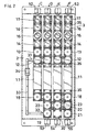
- FIG. 2 is a plan view showing a device layer of the fluid control apparatus of the invention;
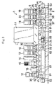
- FIG. 3 is a side elevation of the fluid control apparatus of the invention;
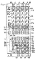
- FIG. 4 is a plan view showing an upper connecting layer;
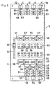
- FIG. 5 is a plan view showing a lower connecting layer;
- FIG. 6 is a side elevation showing the upper and lower connecting layers; and
- FIG. 7 is a view showing a block coupling for lateral communication.
- An embodiment of the present invention will be described below with reference to the drawings.
- FIG. 1 is a piping diagram (in common for conventional fluid control apparatus) corresponding to a fluid control apparatus of the invention. The fluid control apparatus 1 comprises four lines A1, A2, A3, A4 arranged in parallel.
- Each of the lines A1 to A4 is adapted to introduce a purge gas thereinto and comprises a massflow controller 11; an inlet-side first on-off
value 12, inlet-side second on-offvalve 13,pressure sensor 14,pressure regulator 15,filter 16 and inlet-side third on-offvalve 17 which are arranged at the inlet side of the massflow controller 11; and an outlet-side on-offvalve 18 disposed at the outlet side of the massflow controller 11. The lines A1 to A4 are provided at their outlet side with a purge gas inlet on-offvalve 19, purge gas outlet on-offvalve 20 and process gas outlet on-offvalve 21 which are in common for these lines. A purge gas inlet/outlet changeover on-offvalve 22 is interposed between the purge gas inlet on-offvalve 19 and the purge gas outlet on-offvalve 20, and a purge/process gas changeover on-offvalve 23 between the on-offvalve 20 and the process gas outlet on-offvalve 21. The gas piping indicated in solid lines includes purgegas dividing piping 24, purgegas inlet piping 25 and purge-processgas confluent piping 26. - In corresponding relation with the piping diagram of FIG. 1, the fluid control apparatus of the invention has a
device layer 3 shown in FIG. 2, and a connecting layer comprising an upper connectinglayer 4 shown in FIG. 4 and a lower connectinglayer 5 shown in FIG. 5. Thedevice layer 3 is provided by parallel rows each comprising a plurality offluid control devices layer 4 is provided by parallel rows each comprising a plurality ofblock couplings layer 5 comprisesblock couplings base plate 2 and connecting theblock couplings layer 4 in accordance with specifications. - The
device layer 3 is provided by the plurality of rows, i.e., a row C to a row F, in corresponding relation with the piping diagram of FIG. 1. The row C comprises a massflow controller 11; an inlet-side first on-offvalue 12, inlet-side second on-offvalve 13,pressure sensor 14,pressure regulator 15,filter 16 and inlet-side third on-offvalve 17 which are arranged at the inlet side of the massflow controller 11; and an outlet-side on-offvalve 18 disposed at the outlet side of the massflow controller 11. The row D comprises a purge gas inlet on-offvalve 19 and a purge gas inlet/outlet changeover on-offvalve 22 which are added to the components of the row C. The row E comprises a purge gas outlet on-offvalve 20 added to the components of the row C. The row F comprises a process gas outlet on-offvalve 21 and a purge/process gas changeover on-offvalve 23 which are added to the components of the row C. Provided between the inlet-side first on-offvalve 12 of the row C and the purge gas inlet on-offvalve 19 of the row D are acoupling 31 joined to the inlet-side lateralcommunication block coupling 56 of the lower connectinglayer 5, acoupling 32 joined to the outlet-side block coupling 44 of the upper connectinglayer 4, andpiping 33 having aseparable coupling 34 and interconnecting the twocouplings gas inlet piping 25. - The upper connecting
layer 4 is provided in corresponding relation with the rows of thedevice layer 3. A row C and a row F each comprise an inlet-side block coupling 41 and an outlet-side block coupling 42. A row D and a row E each comprise an inlet-side block coupling 41 and two outlet-side block couplings side block couplings 41 are used for the rows. The outlet-side block couplings side block coupling 43 in the row E has twice the length of theblock couplings block couplings shaped channels 61 for holding adjacent fluid control devices in communication with each other, and at least one vertical throughchannel 62. Thesechannels block couplings 41 to 44, as spaced apart by a predetermined distance longitudinally of the block coupling. In FIG. 4, the openings of the V-shaped channels are indicated at 61a, and the openings of thevertical channels 62 are indicated at 62a. Theopenings channels side block coupling 44 in the row E provides a channel for the purge gas outlet on-offvalve 20. The opening 61a not in communication with this on-offvalve 20 is closed with aclosing block 30 of thedevice layer 3. Among the openings provided on opposite sides of thechannels block coupling block coupling layer 5. Theopenings 66 indicated by small single circles are each an internally threaded bore for thescrew 35 to be driven in from above in fastening one of the fluid control devices 11 to 23. - The lower connecting
layer 5 comprises in combination inlet-sidecommunication block couplings 51 connected to inlet-side couplings 52, outlet-sidecommunication block couplings 51 connected to respective outlet-side couplings communication block couplings couplings 51 at opposite sides. The inlet-side couplings 52 and the outlet-side couplings side couplings 52 are used which correspond in number to the number of lines A1 to A4. Three outlet-side couplings are used which are a purgegas inlet coupling 53, purgegas outlet coupling 54 and processgas outlet coupling 55. The lower connectinglayer 5 further includes support blocks 59 having no channel but the same size as the inlet- and outlet-side communication blocks 51 and adapted to support theblock couplings layer 4. - With reference to FIGS. 3 and 6, the inlet-side and outlet-side
communication block couplings 51 of the lower connectinglayer 5 each have an L-shapedlongitudinal communication channel 63 for holding a vertical throughchannel 62 formed in an end portion of each of inlet-side and outlet-side block couplings layer 4 in communication with the inlet-side or outlet-side coupling - The lateral
communication block couplings layer 5 each have alateral channel 64 comprising amain channel 64a extending in a lateral direction, and a plurality ofsubchannels 64b branching out upward from the main channel and opened upward, as illustrated in FIG. 7 which shows an example. Arranged respectively at the inlet side and outlet side of the massflow controller 11 are lateralcommunication block couplings block coupling 56 at the inlet side of the massflow controller 11 corresponds to the purge gas dividing piping 24 of FIG. 1 and has an opening communicating with the purge gas inlet piping 25. Theblock coupling 57 at the outlet side of the massflow controller 11 corresponds to the purge-process gas confluent piping 26 of FIG. 1. Disposed between thisblock coupling 57 and the outlet-sidecommunication block couplings 51 is alateral communication block 58 having a length extending from the row D to the row F. Thisblock 58 serves to connect the purge gas inlet/outlet changeover on-offvalve 22 to the purge/process gas changeover on-offvalve 23. The support blocks 59 are arranged at each of the inlet side and outlet side of the massflow controller 11 and correspond in number to the number of rows. The inlet-side block couplings 41 and the outlet-side block couplings layer 4 are supported, each at the end portion thereof closer to the massflow controller 11, by the support blocks 59. - With reference to FIG. 5, the lateral
communication block couplings lateral communication channels 64 which are all designated by thesame reference numeral 64. The inlet-side and outlet-sidecommunication block couplings 51 have longitudinal communication channels which are all designated by thesame reference numeral 63. The openings of thesechannels channels openings 67 which are indicated by double circles are each a screw insertion bore having a spot facing for a screw to be inserted in for use in fastening the block coupling or thesupport block base plate 2. Theopenings 68 indicated by small single circles are each an internally threaded bore for a screw to be driven in from above in fastening theblock coupling layer 4. - As shown in FIG. 7, one end of each of the lateral
communication block couplings portion 69. If there is no need to attach the coupling, the internally threadedportion 69 is closed with an externally threaded member. - With the fluid control apparatus 1, process gas admitted into the
block coupling 51 of the lower connectinglayer 5 through the inlet-side coupling 52 of each row flows through the inlet-sidefluid control devices device layer 3 which are connected by the inlet-side block coupling 41 of the upper connectinglayer 4 to reach the mass flow controller 11, has its flow rate adjusted, is passed through the outlet-side fluid control devices of thedevice layer 3 which include the on-offvalve 18 and are connected by the outlet-side block coupling 42 of the upper connectinglayer 4, and is discharged toward a process chamber. At this time, the process gas portions through the rows are temporarily collected by the lateralcommunication block coupling 57 for the confluence of gas. The gas is then passed through the lateralcommunication block coupling 58 for a changeover and discharged through the process gas outlet on-offvalve 21 which is manipulated. Purge gas is admitted via the outlet-side coupling 53 in the row D, passed through the piping 33 and then through the lateralcommunication block coupling 56 of the lower connectinglayer 5, introduced into the row C at the position of the inlet-side first on-offvalve 12, thereafter passed through thefluid control devices device layer 3 in the same manner as the process gas and discharged. The purge gas is distributed also to the rows D to F by the lateralcommunication block coupling 56 of the lower connectinglayer 5, is passed through the massflow controllers 11, thereafter flows into the lateralcommunication block coupling 57 for confluence, then flows through the lateralcommunication block coupling 58 for a changeover and is discharged through the purge gas outlet on-offvalve 20 which is manipulated. - The fluid control apparatus of the present invention can be assembled by mounting the block couplings and the support blocks 51, 56, 57, 58, 59 of the lower connecting
layer 5 on thebase plate 2 with screws driven from above, attaching theblock couplings layer 4 to these block couplings and support blocks 51, 56, 57, 48, 59 of the lower connectinglayer 5 from above with screws, and attaching thefluid control devices block couplings layer 4 from above withscrews 35. The components can be assembled without using any horizontal screws or without resorting to welding. The apparatus can be disassembled by a procedure reverse to the above. Thus, the apparatus is easy to assemble and disassemble. The lines can be modified or components may be added by removing and mounting the fluid control devices 11 to 23 as one unit of line, while theblock couplings 41 to 44 of the upper connecting layer can also be removed and mounted as a unit for each line. Thus the apparatus can be modified with ease.
Claims (2)
- A fluid control apparatus comprising a device layer (3) provided by parallel rows each comprising a plurality of fluid control devices (11) (12) (13) (14) (15) (16) (17) (18) (19) (20) (21) (22) (23) arranged in series, and a connecting layer (4) (5) positioned under the device layer, interconnecting the fluid control devices of each of the rows in series and interconnecting the fluid control devices of the adjacent rows in parallel, wherein the connecting layer (4) (5) comprises a lower connecting layer (5) comprising a plurality of block couplings (51) (56) (57) (58) attached to a base plate (2) from above with screws, and an upper connecting layer (4) comprising a plurality of block couplings (41) (42) (43) (44) attached to the block couplings (51) (56) (57) (58) of the lower connecting layer (5) from above with screws (35), wherein the fluid control devices (11-23) are attached to the block couplings (41) (42) (43) (44) of the upper connecting layer (4) from above with screws, and wherein the upper connecting layer (4) is provided by parallel rows each comprising a plurality of block couplings (41) (42) (43) (44) arranged longitudinally of the apparatus, each of the block couplings (41) (42) (43) (44) of the upper connecting layer (4) having a longitudinal channel (61) for interconnecting the adjacent fluid control devices in the row and an upward or downward through channel (62) communicating with one of the fluid control device at a specified location, and the lower connecting layer (5) is provided by at least one lateral communication block coupling (56) (57) (58) having a lateral channel (64) for interconnecting the through channels (62) of the block couplings (41) (42) (43) (44) of the upper connecting layer (4) and by inlet-side and outlet-side communication block couplings (51) each adapted to cause the through channel (62) of the block coupling (41) (43) (44) of the upper connecting layer to communicate with an inlet-side or outlet-side coupling (52) (53) (54) (55) for connection to the outside, characterized in that the longitudinal channel (61) and the through channel (62) of each block coupling (41) (42) (43) (44) of the upper connecting layer (4) are not communicated with each other, the lateral communication block coupling (56) (57) (58) has no longitudinal channel, the lateral channel (64) of the lateral communication block couplings (56) (57) (58) is communicated with all of the through channels (62) of the block couplings (41) (42) (43) (44) of the upper connecting layer (4) associated to these and the lower connecting layer (5) has a support block (59) having the same shape as one of the block couplings (51) (56) (57) (58) of the lower connecting layer (5) and having no channel for supporting the block coupling (41) (42) (43) of the upper connecting layer (4).
- A fluid control apparatus according to claim 1 wherein the device layer (3) has a closing block (30) for closing an upward opening of one of the block coupling (44) included in the upper connecting layer (4).
Applications Claiming Priority (2)
| Application Number | Priority Date | Filing Date | Title |
|---|---|---|---|
| JP2001154359A JP2002349797A (en) | 2001-05-23 | 2001-05-23 | Fluid control device |
| JP2001154359 | 2001-05-23 |
Publications (3)
| Publication Number | Publication Date |
|---|---|
| EP1260743A2 EP1260743A2 (en) | 2002-11-27 |
| EP1260743A3 EP1260743A3 (en) | 2003-05-07 |
| EP1260743B1 true EP1260743B1 (en) | 2006-04-19 |
Family
ID=18998709
Family Applications (1)
| Application Number | Title | Priority Date | Filing Date |
|---|---|---|---|
| EP20020011274 Expired - Lifetime EP1260743B1 (en) | 2001-05-23 | 2002-05-22 | Fluid control apparatus |
Country Status (10)
| Country | Link |
|---|---|
| US (1) | US6868867B2 (en) |
| EP (1) | EP1260743B1 (en) |
| JP (1) | JP2002349797A (en) |
| KR (1) | KR20020090145A (en) |
| CN (1) | CN1386987A (en) |
| CA (1) | CA2387241A1 (en) |
| DE (1) | DE60210702T2 (en) |
| IL (1) | IL149796A0 (en) |
| SG (1) | SG115477A1 (en) |
| TW (1) | TW524945B (en) |
Families Citing this family (37)
| Publication number | Priority date | Publication date | Assignee | Title |
|---|---|---|---|---|
| US7196369B2 (en) * | 2002-07-15 | 2007-03-27 | Macronix International Co., Ltd. | Plasma damage protection circuit for a semiconductor device |
| JP2004183771A (en) * | 2002-12-03 | 2004-07-02 | Fujikin Inc | Fluid control device |
| WO2007017937A1 (en) * | 2005-08-10 | 2007-02-15 | Fujikin Incorporated | Fluid control device |
| US20060070400A1 (en) * | 2004-10-01 | 2006-04-06 | Hussmann Corporation | Modular header system |
| JP4677805B2 (en) * | 2005-03-22 | 2011-04-27 | 株式会社フジキン | Fluid control device |
| US7320339B2 (en) * | 2005-06-02 | 2008-01-22 | Ultra Clean Holdings, Inc. | Gas-panel assembly |
| JP2007046697A (en) * | 2005-08-10 | 2007-02-22 | Fujikin Inc | Jointed fluid controller |
| US7575616B2 (en) * | 2006-02-10 | 2009-08-18 | Entegris, Inc. | Low-profile surface mount filter |
| JP4818835B2 (en) * | 2006-07-04 | 2011-11-16 | 東京エレクトロン株式会社 | Gas supply unit |
| JP5037510B2 (en) * | 2006-08-23 | 2012-09-26 | 株式会社堀場エステック | Integrated gas panel device |
| US8074677B2 (en) * | 2007-02-26 | 2011-12-13 | Applied Materials, Inc. | Method and apparatus for controlling gas flow to a processing chamber |
| JP2008291941A (en) * | 2007-05-25 | 2008-12-04 | Surpass Kogyo Kk | Fluid apparatus unit structure |
| US7806143B2 (en) | 2007-06-11 | 2010-10-05 | Lam Research Corporation | Flexible manifold for integrated gas system gas panels |
| US20090137192A1 (en) * | 2007-11-28 | 2009-05-28 | Mks Instruments, Inc. | Multi-zone pressure control system |
| JP5727703B2 (en) * | 2010-01-27 | 2015-06-03 | 株式会社ダイヘン | Fluid supply device and fuel cell system provided with fluid supply device |
| JP5775696B2 (en) * | 2011-01-31 | 2015-09-09 | 株式会社フジキン | Fluid control device |
| JP5785813B2 (en) * | 2011-08-10 | 2015-09-30 | 株式会社フジキン | Fluid control device |
| WO2013046660A1 (en) | 2011-09-30 | 2013-04-04 | 株式会社フジキン | Gas supply device |
| KR101940325B1 (en) | 2011-10-05 | 2019-01-18 | 가부시키가이샤 호리바 에스텍 | Fluid mechanism, support member constituting fluid mechanism and fluid control system |
| JP6012247B2 (en) * | 2012-04-27 | 2016-10-25 | 株式会社フジキン | Fluid control device |
| JP5616416B2 (en) | 2012-11-02 | 2014-10-29 | 株式会社フジキン | Integrated gas supply device |
| US9454158B2 (en) | 2013-03-15 | 2016-09-27 | Bhushan Somani | Real time diagnostics for flow controller systems and methods |
| JP6147113B2 (en) | 2013-06-27 | 2017-06-14 | 株式会社フジキン | Fitting for fluid control device and fluid control device |
| TWI651486B (en) * | 2013-12-05 | 2019-02-21 | Ckd股份有限公司 | Fluid supply control device |
| JP6346551B2 (en) * | 2013-12-05 | 2018-06-20 | Ckd株式会社 | Flow path block and fluid supply control device |
| JP6486035B2 (en) * | 2014-08-28 | 2019-03-20 | 株式会社フジキン | Manifold valve and fluid control device |
| US9934956B2 (en) * | 2015-07-27 | 2018-04-03 | Lam Research Corporation | Time multiplexed chemical delivery system |
| JP6738095B2 (en) * | 2015-08-26 | 2020-08-12 | 株式会社フジキン | Shunt system |
| JP6082082B2 (en) * | 2015-10-29 | 2017-02-15 | 株式会社堀場エステック | Fluid mechanism and support member constituting the fluid mechanism |
| WO2017130850A1 (en) * | 2016-01-28 | 2017-08-03 | 株式会社フジキン | Fluid control device and method for attaching and detaching gas line section |
| US10983537B2 (en) | 2017-02-27 | 2021-04-20 | Flow Devices And Systems Inc. | Systems and methods for flow sensor back pressure adjustment for mass flow controller |
| JP7061808B2 (en) * | 2017-03-15 | 2022-05-02 | 株式会社フジキン | Fittings and fluid controls |
| US11346505B2 (en) * | 2018-10-26 | 2022-05-31 | Fujikin Incorporated | Fluid supply system, fluid control device, and semiconductor manufacturing device |
| JP7449571B2 (en) * | 2018-12-27 | 2024-03-14 | 株式会社フジキン | Fluid control device, coupling block, and method for manufacturing fluid control device |
| WO2020214616A1 (en) * | 2019-04-15 | 2020-10-22 | Lam Research Corporation | Modular-component system for gas delivery |
| CN112228420B (en) * | 2020-10-15 | 2022-07-19 | 河南恒创精密制造股份有限公司 | Hydraulic block with hydraulic structural element |
| US20220372997A1 (en) * | 2021-05-24 | 2022-11-24 | Festo Se & Co. Kg | Fluid control system |
Family Cites Families (10)
| Publication number | Priority date | Publication date | Assignee | Title |
|---|---|---|---|---|
| JP2731080B2 (en) | 1991-05-31 | 1998-03-25 | 株式会社本山製作所 | Gas control device |
| JPH11159649A (en) * | 1993-02-10 | 1999-06-15 | Ckd Corp | Cylindrical opening/closing valve mounting structure |
| KR100232112B1 (en) * | 1996-01-05 | 1999-12-01 | 아마노 시게루 | Gas supply unit |
| US5836355A (en) * | 1996-12-03 | 1998-11-17 | Insync Systems, Inc. | Building blocks for integrated gas panel |
| US6152175A (en) * | 1997-06-06 | 2000-11-28 | Ckd Corporation | Process gas supply unit |
| US6068016A (en) * | 1997-09-25 | 2000-05-30 | Applied Materials, Inc | Modular fluid flow system with integrated pump-purge |
| US6142164A (en) * | 1998-03-09 | 2000-11-07 | Ultra Clean Technology Systems & Service, Inc. | Method and apparatus for removing leaking gas in an integrated gas panel system |
| JP3780096B2 (en) * | 1998-04-27 | 2006-05-31 | シーケーディ株式会社 | Process gas supply unit |
| JP4244254B2 (en) * | 1999-04-30 | 2009-03-25 | 株式会社キッツエスシーティー | Integrated gas control device |
| US6186177B1 (en) * | 1999-06-23 | 2001-02-13 | Mks Instruments, Inc. | Integrated gas delivery system |
-
2001
- 2001-05-23 JP JP2001154359A patent/JP2002349797A/en active Pending
-
2002
- 2002-05-21 US US10/151,312 patent/US6868867B2/en not_active Expired - Fee Related
- 2002-05-22 KR KR1020020028376A patent/KR20020090145A/en not_active Application Discontinuation
- 2002-05-22 TW TW91110714A patent/TW524945B/en not_active IP Right Cessation
- 2002-05-22 EP EP20020011274 patent/EP1260743B1/en not_active Expired - Lifetime
- 2002-05-22 SG SG200203062A patent/SG115477A1/en unknown
- 2002-05-22 CN CN02120317A patent/CN1386987A/en active Pending
- 2002-05-22 DE DE2002610702 patent/DE60210702T2/en not_active Expired - Fee Related
- 2002-05-22 IL IL14979602A patent/IL149796A0/en unknown
- 2002-05-23 CA CA 2387241 patent/CA2387241A1/en not_active Abandoned
Also Published As
| Publication number | Publication date |
|---|---|
| IL149796A0 (en) | 2002-11-10 |
| DE60210702T2 (en) | 2006-11-09 |
| US20020185185A1 (en) | 2002-12-12 |
| TW524945B (en) | 2003-03-21 |
| US6868867B2 (en) | 2005-03-22 |
| CA2387241A1 (en) | 2002-11-23 |
| KR20020090145A (en) | 2002-11-30 |
| EP1260743A3 (en) | 2003-05-07 |
| JP2002349797A (en) | 2002-12-04 |
| EP1260743A2 (en) | 2002-11-27 |
| CN1386987A (en) | 2002-12-25 |
| DE60210702D1 (en) | 2006-05-24 |
| SG115477A1 (en) | 2005-10-28 |
Similar Documents
| Publication | Publication Date | Title |
|---|---|---|
| EP1260743B1 (en) | Fluid control apparatus | |
| EP0877170B1 (en) | Couplings for fluid controllers | |
| US6035893A (en) | Shutoff-opening devices and fluid control apparatus comprising such devices | |
| US8042573B2 (en) | Fluid control device | |
| EP0845623B1 (en) | Shutoff-opening device | |
| EP1132669B1 (en) | Fluid control apparatus | |
| EP0905383B1 (en) | Fixing means and fluid control apparatus incorporating same | |
| US6874538B2 (en) | Fluid delivery system | |
| US8434522B2 (en) | Fluid control apparatus | |
| US20010003287A1 (en) | Fluid control apparatus | |
| EP1990567B1 (en) | Fluid equipment unit structure | |
| WO2007086394A1 (en) | Pressure sensor device and fluid control device having built-in pressure sensor | |
| US6886599B2 (en) | Gas supply unit | |
| KR20080002914A (en) | Fluid control device | |
| EP0905391B1 (en) | Device for preventing bolt from slipping off | |
| JP3871438B2 (en) | Process gas supply unit | |
| KR102403885B1 (en) | valve apparatus and fluid control apparatus |
Legal Events
| Date | Code | Title | Description |
|---|---|---|---|
| PUAI | Public reference made under article 153(3) epc to a published international application that has entered the european phase |
Free format text: ORIGINAL CODE: 0009012 |
|
| AK | Designated contracting states |
Kind code of ref document: A2 Designated state(s): AT BE CH CY DE DK ES FI FR GB GR IE IT LI LU MC NL PT SE TR |
|
| AX | Request for extension of the european patent |
Free format text: AL;LT;LV;MK;RO;SI |
|
| PUAL | Search report despatched |
Free format text: ORIGINAL CODE: 0009013 |
|
| AK | Designated contracting states |
Designated state(s): AT BE CH CY DE DK ES FI FR GB GR IE IT LI LU MC NL PT SE TR |
|
| AX | Request for extension of the european patent |
Extension state: AL LT LV MK RO SI |
|
| 17P | Request for examination filed |
Effective date: 20030813 |
|
| AKX | Designation fees paid |
Designated state(s): CH DE FR GB IT LI NL |
|
| 17Q | First examination report despatched |
Effective date: 20040224 |
|
| GRAP | Despatch of communication of intention to grant a patent |
Free format text: ORIGINAL CODE: EPIDOSNIGR1 |
|
| GRAS | Grant fee paid |
Free format text: ORIGINAL CODE: EPIDOSNIGR3 |
|
| GRAA | (expected) grant |
Free format text: ORIGINAL CODE: 0009210 |
|
| AK | Designated contracting states |
Kind code of ref document: B1 Designated state(s): CH DE FR GB IT LI NL |
|
| REG | Reference to a national code |
Ref country code: GB Ref legal event code: FG4D |
|
| PGFP | Annual fee paid to national office [announced via postgrant information from national office to epo] |
Ref country code: DE Payment date: 20060422 Year of fee payment: 5 |
|
| PGFP | Annual fee paid to national office [announced via postgrant information from national office to epo] |
Ref country code: NL Payment date: 20060518 Year of fee payment: 5 |
|
| PGFP | Annual fee paid to national office [announced via postgrant information from national office to epo] |
Ref country code: FR Payment date: 20060519 Year of fee payment: 5 |
|
| PGFP | Annual fee paid to national office [announced via postgrant information from national office to epo] |
Ref country code: GB Payment date: 20060524 Year of fee payment: 5 Ref country code: CH Payment date: 20060524 Year of fee payment: 5 |
|
| REF | Corresponds to: |
Ref document number: 60210702 Country of ref document: DE Date of ref document: 20060524 Kind code of ref document: P |
|
| PGFP | Annual fee paid to national office [announced via postgrant information from national office to epo] |
Ref country code: IT Payment date: 20060531 Year of fee payment: 5 |
|
| ET | Fr: translation filed | ||
| PLBE | No opposition filed within time limit |
Free format text: ORIGINAL CODE: 0009261 |
|
| STAA | Information on the status of an ep patent application or granted ep patent |
Free format text: STATUS: NO OPPOSITION FILED WITHIN TIME LIMIT |
|
| 26N | No opposition filed |
Effective date: 20070122 |
|
| REG | Reference to a national code |
Ref country code: CH Ref legal event code: PL |
|
| GBPC | Gb: european patent ceased through non-payment of renewal fee |
Effective date: 20070522 |
|
| PG25 | Lapsed in a contracting state [announced via postgrant information from national office to epo] |
Ref country code: NL Free format text: LAPSE BECAUSE OF NON-PAYMENT OF DUE FEES Effective date: 20071201 |
|
| NLV4 | Nl: lapsed or anulled due to non-payment of the annual fee |
Effective date: 20071201 |
|
| PG25 | Lapsed in a contracting state [announced via postgrant information from national office to epo] |
Ref country code: CH Free format text: LAPSE BECAUSE OF NON-PAYMENT OF DUE FEES Effective date: 20070531 Ref country code: LI Free format text: LAPSE BECAUSE OF NON-PAYMENT OF DUE FEES Effective date: 20070531 |
|
| REG | Reference to a national code |
Ref country code: FR Ref legal event code: ST Effective date: 20080131 |
|
| PG25 | Lapsed in a contracting state [announced via postgrant information from national office to epo] |
Ref country code: DE Free format text: LAPSE BECAUSE OF NON-PAYMENT OF DUE FEES Effective date: 20071201 |
|
| PG25 | Lapsed in a contracting state [announced via postgrant information from national office to epo] |
Ref country code: GB Free format text: LAPSE BECAUSE OF NON-PAYMENT OF DUE FEES Effective date: 20070522 |
|
| PG25 | Lapsed in a contracting state [announced via postgrant information from national office to epo] |
Ref country code: FR Free format text: LAPSE BECAUSE OF NON-PAYMENT OF DUE FEES Effective date: 20070531 |
|
| PG25 | Lapsed in a contracting state [announced via postgrant information from national office to epo] |
Ref country code: IT Free format text: LAPSE BECAUSE OF NON-PAYMENT OF DUE FEES Effective date: 20070522 |