EP1260697A2 - Aufgeladene Brennkraftmaschine - Google Patents
Aufgeladene Brennkraftmaschine Download PDFInfo
- Publication number
- EP1260697A2 EP1260697A2 EP02006429A EP02006429A EP1260697A2 EP 1260697 A2 EP1260697 A2 EP 1260697A2 EP 02006429 A EP02006429 A EP 02006429A EP 02006429 A EP02006429 A EP 02006429A EP 1260697 A2 EP1260697 A2 EP 1260697A2
- Authority
- EP
- European Patent Office
- Prior art keywords
- charge air
- combustion engine
- internal combustion
- outer chamber
- air hose
- Prior art date
- Legal status (The legal status is an assumption and is not a legal conclusion. Google has not performed a legal analysis and makes no representation as to the accuracy of the status listed.)
- Granted
Links
- 238000002485 combustion reaction Methods 0.000 title claims description 21
- 230000008878 coupling Effects 0.000 claims abstract description 6
- 238000010168 coupling process Methods 0.000 claims abstract description 6
- 238000005859 coupling reaction Methods 0.000 claims abstract description 6
- 238000011144 upstream manufacturing Methods 0.000 claims description 3
- 230000003584 silencer Effects 0.000 abstract description 9
- 238000010348 incorporation Methods 0.000 abstract 1
- 238000013016 damping Methods 0.000 description 2
- 230000001419 dependent effect Effects 0.000 description 2
- 238000009434 installation Methods 0.000 description 2
- 230000000694 effects Effects 0.000 description 1
- 238000004519 manufacturing process Methods 0.000 description 1
- 238000007789 sealing Methods 0.000 description 1
Images
Classifications
-
- F—MECHANICAL ENGINEERING; LIGHTING; HEATING; WEAPONS; BLASTING
- F02—COMBUSTION ENGINES; HOT-GAS OR COMBUSTION-PRODUCT ENGINE PLANTS
- F02M—SUPPLYING COMBUSTION ENGINES IN GENERAL WITH COMBUSTIBLE MIXTURES OR CONSTITUENTS THEREOF
- F02M35/00—Combustion-air cleaners, air intakes, intake silencers, or induction systems specially adapted for, or arranged on, internal-combustion engines
- F02M35/12—Intake silencers ; Sound modulation, transmission or amplification
- F02M35/1255—Intake silencers ; Sound modulation, transmission or amplification using resonance
-
- F—MECHANICAL ENGINEERING; LIGHTING; HEATING; WEAPONS; BLASTING
- F02—COMBUSTION ENGINES; HOT-GAS OR COMBUSTION-PRODUCT ENGINE PLANTS
- F02M—SUPPLYING COMBUSTION ENGINES IN GENERAL WITH COMBUSTIBLE MIXTURES OR CONSTITUENTS THEREOF
- F02M35/00—Combustion-air cleaners, air intakes, intake silencers, or induction systems specially adapted for, or arranged on, internal-combustion engines
- F02M35/10—Air intakes; Induction systems
- F02M35/10091—Air intakes; Induction systems characterised by details of intake ducts: shapes; connections; arrangements
- F02M35/10144—Connections of intake ducts to each other or to another device
-
- F—MECHANICAL ENGINEERING; LIGHTING; HEATING; WEAPONS; BLASTING
- F02—COMBUSTION ENGINES; HOT-GAS OR COMBUSTION-PRODUCT ENGINE PLANTS
- F02M—SUPPLYING COMBUSTION ENGINES IN GENERAL WITH COMBUSTIBLE MIXTURES OR CONSTITUENTS THEREOF
- F02M35/00—Combustion-air cleaners, air intakes, intake silencers, or induction systems specially adapted for, or arranged on, internal-combustion engines
- F02M35/12—Intake silencers ; Sound modulation, transmission or amplification
- F02M35/1283—Manufacturing or assembly; Connectors; Fixations
-
- F—MECHANICAL ENGINEERING; LIGHTING; HEATING; WEAPONS; BLASTING
- F02—COMBUSTION ENGINES; HOT-GAS OR COMBUSTION-PRODUCT ENGINE PLANTS
- F02B—INTERNAL-COMBUSTION PISTON ENGINES; COMBUSTION ENGINES IN GENERAL
- F02B29/00—Engines characterised by provision for charging or scavenging not provided for in groups F02B25/00, F02B27/00 or F02B33/00 - F02B39/00; Details thereof
- F02B29/04—Cooling of air intake supply
Definitions
- the invention relates to an internal combustion engine, in particular for a motor vehicle a supercharger which compresses a charge air and which has a compressor pressure connection has, an intake tract, the compressor pressure port of the charger with the Intake tract connecting the charge air hose and one in the air flow of the charge air arranged silencer, according to the preamble of claim 1.
- a charge air hose for an internal combustion engine is used to conduct charge air a charger, for example an exhaust gas turbocharger, directly or via a Charge air cooler to an intake tract of the internal combustion engine.
- a charger for example an exhaust gas turbocharger
- Charge air cooler to an intake tract of the internal combustion engine.
- Such one Charge air hose is known from DE 195 06 584 C1 and consists of a flexible Material to measure relative movements between the charger and the charge air cooler To be able to compensate for the internal combustion engine.
- the well-known charge air hose is also provided with folds whose outer diameter is larger than the outer diameter of the charge air hose. In these folds there is one inside the charge air hose annular rigid insert introduced, whereby the axial elongation of the Charge air hose under internal pressure and thus the transfer of forces between the Components should be reduced.
- the present invention is therefore based on the object, a charged Internal combustion engine of the above type with improved charge air supply To make available.
- the noise damper in a clutch is integrated between the charge air hose and the compressor pressure port so that the Muffler on the one hand in the compressor discharge nozzle and on the other hand in the Charge air hose engages.
- the noise damper has an inner tube, which forms a first and a second outer chamber, the first chamber engages in the compressor pressure nozzle and with it via at least one first opening is connected and the second chamber engages in and with the charge air hose at least one second opening is connected, the inner tube also being in two parts is formed, wherein a first part of the first outer chamber and a second part forms the second outer chamber and the two parts at a joint each bent into a flange and connected to each other on the flange, in particular are welded together.
- the noise damper has an outer contour, which surrounds the inner tube and is located downstream of the second chamber in the Inner diameter narrowed and together with the charge air hose a third outer one Chamber trains.
- the outer contour comprises one upstream of the first chamber Faceplate.
- the charge air hose is in the area of the second outer chamber on the Outer contour and this spanned and the compressor discharge nozzle is in Area of the first outer chamber on the outer contour and overlapping this executed.
- the outer contour is also formed in two parts, with a first part first outer chamber and a second part encloses the second outer chamber and the two parts being bent and joined at a joint to form a flange the flange connected to each other and to the flange of the parts of the inner tube, in particular are welded together.
- the charger is an exhaust gas turbocharger, a pressure wave charger or a mechanical loader.
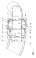
- Fig. 1 is the connection point between a compressor discharge nozzle 10 and a Charge air hose 12 of an internal combustion engine, which is otherwise not shown in detail shown.
- the compressor pressure nozzle 10 comes from a charger, not shown and the charge air hose 12 leads to an intake tract, not shown Internal combustion engine, optionally with an intercooler between the charge air hose 12 and intake tract is arranged.
- a noise damper formed which comprises: an inner tube 14 having a first part 16 and second part 18 and an outer contour 20, which is also a first part 22 and a has second part 24.
- the first part 16 of the inner tube 14 forms a first outer Chamber 26 out and is with the compressor discharge nozzle 10 via a first slot 28th connected.
- the second part 18 of the inner tube 14 forms a second outer chamber 30 and is connected to the charge air hose 12 via a second slot 32.
- On a joint 34 between the first and second parts 16, 18 are flange-like formed or molded and welded together.
- the first part 22 of the outer contour 20 surrounds the first chamber 26 and is a contour of the compressor pressure connector 10 following. Upstream of the first outer Chamber 26 has an end plate 36 arranged on the first part 22 of the outer contour 20. This end plate 36 is optionally also in one piece with the first part 22 of the outer contour 20 trained.
- the first part 22 of the outer contour 20 is also at the joint 34 formed like a flange and with corresponding flange sections 38 of the inner tube 14 welded. This section of the noise damper 16, 22 just described 26, 28, 36, which lies in the single figure to the right of the joint 34, projects completely into the compressor pressure connector 10 into it.
- the second part 24 of the outer contour 20 surrounds the second outer chamber 30 and narrows downstream of the second outer chamber 30 or the second slot 32 in Inner diameter such that between the narrowed part 40 of the outer contour 20 and the charge air hose 12 results in a third outer chamber 50.
- Section 40 the outer contour 20 surrounds an outlet 42 from the second outer chamber 30.
- the second part 24 of the outer contour 20 is also flange-like at the joint 34 formed and with the flange portions 38 of the inner tube 14 and with the Flange section of the first part 22 of the outer contour 20 welded. This just now described section of the silencer 18, 24, 30, 32, 40, 42, which in the only the left of the joint 34 protrudes completely into the charge air hose 12 into it.
- the silencer is except for the joint 34 within the charge air hose 12 or Compressor pressure connector 10 arranged and forms a coupling element. Consequently are the functions "internal coupling element between Compressor pressure nozzle 10 and charge air hose 12 "as well as” noise damper "in one integrated single component.
- At 48 are two recesses for one, not shown Clamp can be seen in which this clamp engages and which by means of Noise-damping coupling locked in the compressor discharge nozzle 10.
- the two outer chambers 26 and 30 are closed at the joint 34, so that no flow takes place here.
- the outer chambers 26 and 30 are closed at each of the joints 34 facing away.
- the third outer chamber 50 is only in the direction of Charge air hose open 12. In these chambers 26, 30, 50 it only happens vortex-like movements of the charge air. Overall, the system yields with the outer Chambers 26, 30, 50 in connection with the inner tube 14 a noise-damping Effect.
Landscapes
- Engineering & Computer Science (AREA)
- Chemical & Material Sciences (AREA)
- Combustion & Propulsion (AREA)
- Mechanical Engineering (AREA)
- General Engineering & Computer Science (AREA)
- Manufacturing & Machinery (AREA)
- Supercharger (AREA)
Abstract
Description
- 10
- Verdichterdruckstutzen
- 12
- Ladeluftschlauch
- 14
- Innenrohr
- 16
- erstes Teil des Innenrohrs
- 18
- zweites Teil des Innenrohrs
- 20
- Außenkontur
- 22
- erstes Teil des Außenkontur
- 24
- zweites Teil des Außenkontur
- 26
- erste äußere Kammer
- 28
- erster Schlitz
- 30
- zweite äußere Kammer
- 32
- zweiter Schlitz
- 34
- Stoßstelle
- 36
- Stirnplatte
- 38
- Flanschabschnitt
- 40
- verengter Teil der Außenkontur
- 42
- Austritt
- 44
- Dichtring
- 46
- Schelle
- 48
- Ausnehmung
- 50
- dritte äußere Kammer
Claims (11)
- Brennkraftmaschine, insbesondere für ein Kraftfahrzeug, mit einem eine Ladeluft verdichtenden Lader, welcher einen Verdichterdruckstutzen (10) aufweist, einem Ansaugtrakt, einem den Verdichterdruckstutzen (10) des Laders mit dem Ansaugtrakt verbindenden Ladeluftschlauch (12) und einem im Luftstrom der Ladeluft angeordneten Geräuschdämpfer, dadurch gekennzeichnet, daß der Geräuschdämpfer (14, 20) in eine Kupplung zwischen Ladeluftschlauch (12) und Verdichterdruckstutzen (10) derart integriert ist, daß der Geräuschdämpfer (14, 20) einerseits in den Verdichterdruckstutzen (10) und andererseits in den Ladeluftschlauch (12) eingreift.
- Brennkraftmaschine nach Anspruch 1, dadurch gekennzeichnet, daß der Geräuschdämpfer ein Innenrohr (14) aufweist, welches eine erste äußere Kammer (26) und eine zweite äußere Kammer (30) ausbildet, wobei die erste äußere Kammer (26) in den Verdichterdruckstutzen (10) greift und mit diesem über wenigstens eine erste Öffnung (28) verbunden ist und die zweite äußere Kammer (30) in den Ladeluftschlauch (12) greift und mit diesem über wenigstens eine zweite Öffnung (32) verbunden ist.
- Brennkraftmaschine nach Anspruch 2, dadurch gekennzeichnet, daß das Innenrohr (14) zweiteilig ausgebildet ist, wobei ein erstes Teil (16) die erste äußere Kammer (26) und ein zweites Teil (18) die zweite äußere Kammer (30) ausbildet und wobei die beiden Teile (16, 18) an einer Stoßstelle (34) jeweils zu einem Flansch (38) gebogen und an dem Flansch (38) miteinander verbunden, insbesondere miteinander verschweißt sind.
- Brennkraftmaschine nach Anspruch 2 oder 3, dadurch gekennzeichnet, daß der Geräuschdämpfer eine Außenkontur (20) aufweist, welche das Innenrohr (14) umschließt und sich stromab der zweiten äußeren Kammer (30) im Innendurchmesser verengt und zusammen mit dem Ladeluftschlauch (12) eine dritte äußere Kammer (50) ausbildet.
- Brennkraftmaschine nach Anspruch 4, dadurch gekennzeichnet, daß die Außenkontur (20) stromauf der ersten äußeren Kammer (26) eine Stirnplatte (36) aufweist.
- Brennkraftmaschine nach Anspruch 4 oder 5, dadurch gekennzeichnet, daß der Ladeluftschlauch (12) im Bereich der zweiten äußeren Kammer (30) auf der Außenkontur (20) und diese übergreifend befestigt ist.
- Brennkraftmaschine nach wenigstens einem der Ansprüche 4 bis 6, dadurch gekennzeichnet, daß der Verdichterdruckstutzen (10) im Bereich der ersten äußeren Kammer (26) die Außenkontur (20) übergreifend ausgebildet ist.
- Brennkraftmaschine nach Anspruch 3 und wenigstens einem der Ansprüche 4 bis 7, dadurch gekennzeichnet, daß die Außenkontur (20) zweiteilig ausgebildet ist, wobei ein erstes Teil (22) die erste äußere Kammer (26) und ein zweites Teil (24) die zweite äußere Kammer (30) umschließt und wobei die beiden Teile (22, 24) an einer Stoßstelle (34) jeweils zu einem Flansch (38) gebogen und an dem Flansch (38) miteinander und mit dem Flansch (38) der Teile (16, 18) des Innenrohres (14) verbunden, insbesondere miteinander verschweißt sind.
- Brennkraftmaschine nach Anspruch 8, dadurch gekennzeichnet, daß das erste Teil (22) der Außenkontur (20) einer Innenkontur des Verdichterdruckstutzens (10) folgend ausgebildet ist.
- Brennkraftmaschine nach wenigstens einem der vorhergehenden Ansprüche, dadurch gekennzeichnet, daß der Lader ein Abgasturbolader, ein Druckwellenlader oder ein mechanischer Lader ist.
- Brennkraftmaschine nach wenigstens einem der vorhergehenden Ansprüche, dadurch gekennzeichnet, daß zwischen Ladeluftschlauch (12) und Ansaugtrakt ein Ladeluftkühler angeordnet ist.
Applications Claiming Priority (2)
| Application Number | Priority Date | Filing Date | Title |
|---|---|---|---|
| DE2001125551 DE10125551A1 (de) | 2001-05-23 | 2001-05-23 | Aufgeladene Brennkraftmaschine |
| DE10125551 | 2001-05-23 |
Publications (3)
| Publication Number | Publication Date |
|---|---|
| EP1260697A2 true EP1260697A2 (de) | 2002-11-27 |
| EP1260697A3 EP1260697A3 (de) | 2003-11-12 |
| EP1260697B1 EP1260697B1 (de) | 2006-03-29 |
Family
ID=7686137
Family Applications (1)
| Application Number | Title | Priority Date | Filing Date |
|---|---|---|---|
| EP20020006429 Expired - Lifetime EP1260697B1 (de) | 2001-05-23 | 2002-03-22 | Aufgeladene Brennkraftmaschine |
Country Status (2)
| Country | Link |
|---|---|
| EP (1) | EP1260697B1 (de) |
| DE (2) | DE10125551A1 (de) |
Cited By (13)
| Publication number | Priority date | Publication date | Assignee | Title |
|---|---|---|---|---|
| GB2389149A (en) * | 2001-09-07 | 2003-12-03 | Avon Polymer Prod Ltd | Noise suppressor eg for vehicular turbocharger duct |
| US6983820B2 (en) | 2001-09-07 | 2006-01-10 | Avon Polymer Products Limited | Noise and vibration suppressors |
| DE102006038830A1 (de) * | 2006-08-18 | 2008-02-21 | Volkswagen Ag | Lader für eine Brennkraftmaschine und eine Brennkraftmaschine mit einem Lader |
| FR2912201A1 (fr) * | 2007-02-02 | 2008-08-08 | Trelleborg Fluid & Acoustic Solutions Tfas | Dispositif d'attenuation des bruits pour circuit d'admission de fluide gazeux |
| EP2128425A1 (de) * | 2008-05-30 | 2009-12-02 | Hutchinson | Vorrichtung zur Geräuschdämpfung für eine Ansaugleitung einer Brennkraftmaschine und Ansaugleitung, die diese Vorrichtung umfasst |
| DE102010020064A1 (de) * | 2010-05-11 | 2011-11-17 | Bayerische Motoren Werke Aktiengesellschaft | Schalldämpferanordnung für eine insbesondere aufgeladene Kraftfahrzeug-Brennkraftmaschine |
| DE102011002869A1 (de) * | 2011-01-19 | 2012-07-19 | Siemens Aktiengesellschaft | Reflektionsschalldämpfer |
| WO2013152793A1 (de) * | 2012-04-12 | 2013-10-17 | Siemens Aktiengesellschaft | Reflektionsschalldämpfer |
| CN106103964A (zh) * | 2014-03-07 | 2016-11-09 | 亨恩有限及两合股份公司 | 消声器 |
| EP3020955A4 (de) * | 2013-07-09 | 2017-03-01 | Nok Corporation | Dichtungsvorrichtung |
| US10495113B2 (en) | 2017-02-14 | 2019-12-03 | Garrett Transporation I Inc. | Acoustic damper with resonator members arranged in-parallel |
| CN110651114A (zh) * | 2017-05-22 | 2020-01-03 | 曼·胡默尔有限公司 | 用于降低内燃机的进气系统中的气体噪声的消声器及此消声器的制造方法 |
| US10533452B2 (en) | 2017-07-19 | 2020-01-14 | Garrett Transportation I Inc. | Acoustic damper with barrier member configured to dampen acoustic energy propogating upstream in gas flow |
Families Citing this family (1)
| Publication number | Priority date | Publication date | Assignee | Title |
|---|---|---|---|---|
| CN102644531B (zh) * | 2011-02-16 | 2015-02-25 | 曼·胡默尔有限公司 | 谐振系统 |
Citations (2)
| Publication number | Priority date | Publication date | Assignee | Title |
|---|---|---|---|---|
| DE19506584C1 (de) | 1995-02-24 | 1996-05-15 | Daimler Benz Ag | Flexible Schlauchleitung |
| DE19960427C1 (de) | 1999-12-15 | 2001-02-08 | Muendener Gummiwerk Gmbh | Ladeluftschlauch und Verfahren zur Herstellung eines Ladeluftschlauchs |
Family Cites Families (3)
| Publication number | Priority date | Publication date | Assignee | Title |
|---|---|---|---|---|
| DE3531353A1 (de) * | 1985-09-03 | 1987-03-12 | Audi Ag | Ladeluftkuehler fuer aufgeladene brennkraftmaschine |
| DE19855708B4 (de) * | 1998-12-03 | 2009-04-30 | Denker, Dietrich, Prof. Dr.-Ing. | Rohrkammerdämpfer |
| DE19943246B4 (de) * | 1999-09-10 | 2006-06-14 | Daimlerchrysler Ag | Schalldämpfer zur Herabminderung der Luftgeräusche im Ansaugstrang von Brennkraftmaschinen |
-
2001
- 2001-05-23 DE DE2001125551 patent/DE10125551A1/de not_active Withdrawn
-
2002
- 2002-03-22 EP EP20020006429 patent/EP1260697B1/de not_active Expired - Lifetime
- 2002-03-22 DE DE50206182T patent/DE50206182D1/de not_active Expired - Lifetime
Patent Citations (2)
| Publication number | Priority date | Publication date | Assignee | Title |
|---|---|---|---|---|
| DE19506584C1 (de) | 1995-02-24 | 1996-05-15 | Daimler Benz Ag | Flexible Schlauchleitung |
| DE19960427C1 (de) | 1999-12-15 | 2001-02-08 | Muendener Gummiwerk Gmbh | Ladeluftschlauch und Verfahren zur Herstellung eines Ladeluftschlauchs |
Cited By (21)
| Publication number | Priority date | Publication date | Assignee | Title |
|---|---|---|---|---|
| GB2389149A (en) * | 2001-09-07 | 2003-12-03 | Avon Polymer Prod Ltd | Noise suppressor eg for vehicular turbocharger duct |
| GB2389149B (en) * | 2001-09-07 | 2004-08-25 | Avon Polymer Prod Ltd | Noise and vibration suppressors |
| US6983820B2 (en) | 2001-09-07 | 2006-01-10 | Avon Polymer Products Limited | Noise and vibration suppressors |
| DE102006038830A1 (de) * | 2006-08-18 | 2008-02-21 | Volkswagen Ag | Lader für eine Brennkraftmaschine und eine Brennkraftmaschine mit einem Lader |
| DE102006038830B4 (de) * | 2006-08-18 | 2017-04-27 | Volkswagen Ag | Lader für eine Brennkraftmaschine und eine Brennkraftmaschine mit einem Lader |
| FR2912201A1 (fr) * | 2007-02-02 | 2008-08-08 | Trelleborg Fluid & Acoustic Solutions Tfas | Dispositif d'attenuation des bruits pour circuit d'admission de fluide gazeux |
| EP1956281A1 (de) | 2007-02-02 | 2008-08-13 | Trelleborg Fluid & Acoustic Solutions (TFAS) | Vorrichtung zur Schalldämpfung für Zuführkreislauf von gasförmigen Fluiden |
| EP2128425A1 (de) * | 2008-05-30 | 2009-12-02 | Hutchinson | Vorrichtung zur Geräuschdämpfung für eine Ansaugleitung einer Brennkraftmaschine und Ansaugleitung, die diese Vorrichtung umfasst |
| FR2931901A1 (fr) * | 2008-05-30 | 2009-12-04 | Hutchinson | Dispositif d'attenuation acoustique pour ligne d'admission d'un moteur thermique,et ligne d'admission l'incorporant. |
| DE102010020064A1 (de) * | 2010-05-11 | 2011-11-17 | Bayerische Motoren Werke Aktiengesellschaft | Schalldämpferanordnung für eine insbesondere aufgeladene Kraftfahrzeug-Brennkraftmaschine |
| DE102010020064B4 (de) * | 2010-05-11 | 2019-10-02 | Bayerische Motoren Werke Aktiengesellschaft | Schalldämpferanordnung für eine insbesondere aufgeladene Kraftfahrzeug-Brennkraftmaschine |
| DE102011002869A1 (de) * | 2011-01-19 | 2012-07-19 | Siemens Aktiengesellschaft | Reflektionsschalldämpfer |
| DE102011002869B4 (de) * | 2011-01-19 | 2014-08-07 | Siemens Aktiengesellschaft | Reflektionsschalldämpfer |
| WO2013152793A1 (de) * | 2012-04-12 | 2013-10-17 | Siemens Aktiengesellschaft | Reflektionsschalldämpfer |
| EP3020955A4 (de) * | 2013-07-09 | 2017-03-01 | Nok Corporation | Dichtungsvorrichtung |
| CN106103964B (zh) * | 2014-03-07 | 2019-08-23 | 亨恩有限及两合股份公司 | 消声器 |
| CN106103964A (zh) * | 2014-03-07 | 2016-11-09 | 亨恩有限及两合股份公司 | 消声器 |
| US10495113B2 (en) | 2017-02-14 | 2019-12-03 | Garrett Transporation I Inc. | Acoustic damper with resonator members arranged in-parallel |
| CN110651114A (zh) * | 2017-05-22 | 2020-01-03 | 曼·胡默尔有限公司 | 用于降低内燃机的进气系统中的气体噪声的消声器及此消声器的制造方法 |
| CN110651114B (zh) * | 2017-05-22 | 2022-09-09 | 曼·胡默尔有限公司 | 用于降低内燃机的进气系统中的气体噪声的消声器及此消声器的制造方法 |
| US10533452B2 (en) | 2017-07-19 | 2020-01-14 | Garrett Transportation I Inc. | Acoustic damper with barrier member configured to dampen acoustic energy propogating upstream in gas flow |
Also Published As
| Publication number | Publication date |
|---|---|
| DE50206182D1 (de) | 2006-05-18 |
| DE10125551A1 (de) | 2002-11-28 |
| EP1260697B1 (de) | 2006-03-29 |
| EP1260697A3 (de) | 2003-11-12 |
Similar Documents
| Publication | Publication Date | Title |
|---|---|---|
| EP1260697B1 (de) | Aufgeladene Brennkraftmaschine | |
| DE19830154B4 (de) | Kombinierter Betriebsbrems- und Federspeicherbremszylinder | |
| DE3529543C2 (de) | ||
| EP2501922B1 (de) | Saugrohrabschnitt und sauganlage | |
| DE102011110285A1 (de) | Ansaugrohrelement und Verdichteranordnung daraus | |
| EP2757235B1 (de) | Schalldämpfer und Verfahren zu seiner Herstellung | |
| EP1206633B1 (de) | Ansaugeinrichtung für eine brennkraftmaschine | |
| EP1788216A1 (de) | Übersprecher für eine Abgasanlage | |
| DE102010020064B4 (de) | Schalldämpferanordnung für eine insbesondere aufgeladene Kraftfahrzeug-Brennkraftmaschine | |
| EP1270917B1 (de) | Zwischenflanschsystem für eine direkteinspritzende Brennkraftmaschine | |
| DE102012020420A1 (de) | Verzweigungs- oder Zusammenführungselement für gasförmige Fluide | |
| DE20122620U1 (de) | Aufgeladene Brennkraftmaschine | |
| DE19846281A1 (de) | Luftführungssystem, insbesondere Saugsystem einer Verbrennungskraftmaschine | |
| EP0731258B1 (de) | Abgaskrümmer | |
| EP2496840B1 (de) | Ansauggehäuse | |
| DE10317224A1 (de) | Vorrichtung zur Reduzierung von Schallemissionen | |
| EP2818682B1 (de) | Anschlussanordnung | |
| EP1058782B1 (de) | Ansaugvorrichtung für eine brennkraftmaschine | |
| DE10216721B4 (de) | Verbindungssystem für die form-und/oder kraftschlüssige Verbindung zweier Bauteile | |
| DE10353431B4 (de) | Wellendurchführung an einem Luftansaugkanalsystem | |
| DE102020112870B4 (de) | Verdichtervorrichtung einer Aufladevorrichtung für eine Brennkraftmaschine | |
| DE102010044064B4 (de) | Katalysator und Abgasanlage | |
| DE102004053844B3 (de) | Unterdruck-Bremskraftverstärker für Kraftfahrzeuge | |
| DE102016111561A1 (de) | Verbindungseinrichtung zum gasdichten Verbinden von rohr- und/oder stutzenförmigen Bauteilen | |
| EP3268599A1 (de) | Saugmodul einer frischluftanlage |
Legal Events
| Date | Code | Title | Description |
|---|---|---|---|
| PUAI | Public reference made under article 153(3) epc to a published international application that has entered the european phase |
Free format text: ORIGINAL CODE: 0009012 |
|
| AK | Designated contracting states |
Kind code of ref document: A2 Designated state(s): AT BE CH CY DE DK ES FI FR GB GR IE IT LI LU MC NL PT SE TR |
|
| AX | Request for extension of the european patent |
Free format text: AL;LT;LV;MK;RO;SI |
|
| PUAL | Search report despatched |
Free format text: ORIGINAL CODE: 0009013 |
|
| AK | Designated contracting states |
Kind code of ref document: A3 Designated state(s): AT BE CH CY DE DK ES FI FR GB GR IE IT LI LU MC NL PT SE TR |
|
| AX | Request for extension of the european patent |
Extension state: AL LT LV MK RO SI |
|
| 17P | Request for examination filed |
Effective date: 20040512 |
|
| AKX | Designation fees paid |
Designated state(s): DE ES FR GB IT |
|
| 17Q | First examination report despatched |
Effective date: 20040701 |
|
| GRAP | Despatch of communication of intention to grant a patent |
Free format text: ORIGINAL CODE: EPIDOSNIGR1 |
|
| GRAS | Grant fee paid |
Free format text: ORIGINAL CODE: EPIDOSNIGR3 |
|
| GRAA | (expected) grant |
Free format text: ORIGINAL CODE: 0009210 |
|
| AK | Designated contracting states |
Kind code of ref document: B1 Designated state(s): DE ES FR GB IT |
|
| PG25 | Lapsed in a contracting state [announced via postgrant information from national office to epo] |
Ref country code: IT Free format text: LAPSE BECAUSE OF FAILURE TO SUBMIT A TRANSLATION OF THE DESCRIPTION OR TO PAY THE FEE WITHIN THE PRESCRIBED TIME-LIMIT;WARNING: LAPSES OF ITALIAN PATENTS WITH EFFECTIVE DATE BEFORE 2007 MAY HAVE OCCURRED AT ANY TIME BEFORE 2007. THE CORRECT EFFECTIVE DATE MAY BE DIFFERENT FROM THE ONE RECORDED. Effective date: 20060329 |
|
| REG | Reference to a national code |
Ref country code: GB Ref legal event code: FG4D Free format text: NOT ENGLISH |
|
| REF | Corresponds to: |
Ref document number: 50206182 Country of ref document: DE Date of ref document: 20060518 Kind code of ref document: P |
|
| PG25 | Lapsed in a contracting state [announced via postgrant information from national office to epo] |
Ref country code: ES Free format text: LAPSE BECAUSE OF FAILURE TO SUBMIT A TRANSLATION OF THE DESCRIPTION OR TO PAY THE FEE WITHIN THE PRESCRIBED TIME-LIMIT Effective date: 20060710 |
|
| GBT | Gb: translation of ep patent filed (gb section 77(6)(a)/1977) |
Effective date: 20060717 |
|
| PLBE | No opposition filed within time limit |
Free format text: ORIGINAL CODE: 0009261 |
|
| STAA | Information on the status of an ep patent application or granted ep patent |
Free format text: STATUS: NO OPPOSITION FILED WITHIN TIME LIMIT |
|
| 26N | No opposition filed |
Effective date: 20070102 |
|
| EN | Fr: translation not filed | ||
| PG25 | Lapsed in a contracting state [announced via postgrant information from national office to epo] |
Ref country code: FR Free format text: LAPSE BECAUSE OF FAILURE TO SUBMIT A TRANSLATION OF THE DESCRIPTION OR TO PAY THE FEE WITHIN THE PRESCRIBED TIME-LIMIT Effective date: 20070309 |
|
| PG25 | Lapsed in a contracting state [announced via postgrant information from national office to epo] |
Ref country code: FR Free format text: LAPSE BECAUSE OF FAILURE TO SUBMIT A TRANSLATION OF THE DESCRIPTION OR TO PAY THE FEE WITHIN THE PRESCRIBED TIME-LIMIT Effective date: 20060329 |
|
| REG | Reference to a national code |
Ref country code: DE Ref legal event code: R084 Ref document number: 50206182 Country of ref document: DE Effective date: 20111008 |
|
| PGFP | Annual fee paid to national office [announced via postgrant information from national office to epo] |
Ref country code: DE Payment date: 20140331 Year of fee payment: 13 |
|
| PGFP | Annual fee paid to national office [announced via postgrant information from national office to epo] |
Ref country code: GB Payment date: 20140331 Year of fee payment: 13 |
|
| REG | Reference to a national code |
Ref country code: DE Ref legal event code: R119 Ref document number: 50206182 Country of ref document: DE |
|
| GBPC | Gb: european patent ceased through non-payment of renewal fee |
Effective date: 20150322 |
|
| PG25 | Lapsed in a contracting state [announced via postgrant information from national office to epo] |
Ref country code: DE Free format text: LAPSE BECAUSE OF NON-PAYMENT OF DUE FEES Effective date: 20151001 Ref country code: GB Free format text: LAPSE BECAUSE OF NON-PAYMENT OF DUE FEES Effective date: 20150322 |