EP1260376A2 - Thermal transfer color printing method and apparatus - Google Patents
Thermal transfer color printing method and apparatus Download PDFInfo
- Publication number
- EP1260376A2 EP1260376A2 EP02356097A EP02356097A EP1260376A2 EP 1260376 A2 EP1260376 A2 EP 1260376A2 EP 02356097 A EP02356097 A EP 02356097A EP 02356097 A EP02356097 A EP 02356097A EP 1260376 A2 EP1260376 A2 EP 1260376A2
- Authority
- EP
- European Patent Office
- Prior art keywords
- ribbons
- block
- printing
- support
- ribbon
- Prior art date
- Legal status (The legal status is an assumption and is not a legal conclusion. Google has not performed a legal analysis and makes no representation as to the accuracy of the status listed.)
- Withdrawn
Links
Images


Classifications
-
- B—PERFORMING OPERATIONS; TRANSPORTING
- B41—PRINTING; LINING MACHINES; TYPEWRITERS; STAMPS
- B41J—TYPEWRITERS; SELECTIVE PRINTING MECHANISMS, i.e. MECHANISMS PRINTING OTHERWISE THAN FROM A FORME; CORRECTION OF TYPOGRAPHICAL ERRORS
- B41J35/00—Other apparatus or arrangements associated with, or incorporated in, ink-ribbon mechanisms
- B41J35/22—Mechanisms permitting the selective use of a plurality of ink ribbons
Definitions
- the present invention relates to the color printing technique of a printable support using a known thermal transfer process, consisting of to ensure, by localized heat supply, the transfer of dyes carried by a suitable substrate, towards a receiving support on which these dyes are fixed.
- the invention relates, more particularly, to the technical field in which this basic principle is implemented by means of technical provisions ensuring the transfer of points which, by color combination according to the principle of synthesis additive or subtractive synthesis, give rise to the formation of images composed, of multiple and varied colors.
- the technical field concerned is, more particularly, that of printing. supports in the form of boards, strips, sheets, in any suitable material compatible with receiving and fixing colored pigments and whose destination finish can be varied.
- Such a technique is widely used for the creation of billboards or advertising panels.
- the implementation of such a technique consists in unwinding, from a storage roll, a strip of suitable material constituting a support which is engaged in a device to bring back, on this support, a colored impression which is, generally, controlled, in its form, in the choice of colors, by through a computer center requiring the device to run a number of passes to form the pattern and obtain the combination of desired colors.
- thermal transfer of the dyes is carried out by passing successive, from a supply of dyes carried by a ribbon or the like, stored in a cake which should be changed for each pass and for each color.
- Another proposal of the prior art has been to provide a device color printing by thermal transfer of a single wafer or spool bearing a ribbon which is composed of successive series of segments of primary colors, such as three or four, which are thus renewed from series to series.
- the operating technique of such a device then consists in placing, under the print head, the segment of a series of ribbon corresponding to the color desired, then unroll the ribbon for the next pass, so as to route, under the head, the segment of the different or complementary color that is appropriate printing.
- the object of the invention is to meet the need to be able to have a printing technique on printable support by thermal transfer of dyes, which is able to involve an attractive acquisition cost for what relates to the technical means to be implemented and which allows obtaining of various colored patterns at a unit price per unit area which is also interesting.
- Another object of the invention is to offer a technique which allows a execution of patterns of large areas, of relative complexity, of good definition and various colors, at a production rate significantly faster than that of the devices currently available.
- the invention also relates to a spool for a ribbon for printing by heat transfer, of the type comprising a ribbon winding mandrel.
- this coil is characterized in that it comprises, in in addition, a hub for limiting the rotational torque of the mandrel.
- the torque limiting hub can be made in any suitable way and, by example, using viscous coupling means.
- the limiting hub of couple comprises a sleeve which is integral with the mandrel and produced in a compressible material and which defines the receiving bore of a drive axis of the coil.
- the sleeve is then made of cellular synthetic material, such as, for example but not exclusively, a crosslinked polyethylene foam which preferably, but not strictly necessary, has a density between 40 and 50 kg / m 3 .
- the torque limiting hub is, from preferably adapted to limit the drive torque to a value between 0.5 N / cm and 2 N / cm, so as to apply tension to the printing ribbon sufficient without risking damage to the latter.
- the coil comprises flanges.
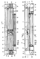
- Fig. 1 is a schematic perspective of the device according to the invention.
- Fig. 2 is a partial perspective, similar to FIG. 1, but illustrating a characteristic arrangement of the device.
- Fig. 3 is a sectional elevation taken substantially along the plane III-III of FIG. 1.
- Fig. 4 is a plan view in section taken along line IV-IV of FIG. 3.
- Fig. 5 is a cross section taken, on a larger scale, along the line VV of FIG. 3.
- Fig. 6 is a partial plan view taken along line VI-VI of FIG. 5.
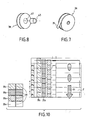
- Figs. 7 and 8 are partial perspectives showing, on a different scale, two constituent elements of the device.
- Fig. 9 is a partial schematic perspective view of a winding assembly for the printing ribbon of the device illustrated in FIG. 1.
- Fig. 10 is a schematic view illustrating, more particularly, an initial characteristic phase of implementing the method according to the invention.
- Figs. 11, 12 and 13 are schematic views illustrating three specific steps for implementing the method.
- Figs. 1 and 2 show , schematically, a device 1 for implementing the process for printing a support 2 by thermal transfer of dyes or pigments.
- the support 2 is constituted by a strip coming from a storage roller 3 and unwound in the direction of the arrow f 1 , denoted by convention in what follows "longitudinal direction".
- the device is placed, for its operation, under the dependence of a unit 4 for storing computer data and for controlling the various motor and active constituent parts of the device, in relation to a program for establishing a colored pattern, such as than that shown in dashed lines under the reference 5 in FIG. 1.
- the device comprises structurally, from FIGS. 1 to 4 , a frame 5 consisting of spacer members linked by parallel cheeks 6 , associated with cowls 7 with which they delimit two compartments 8 and 9 whose functions appear in the following.
- the frame 5 delimits a window or through passage 10 (fig. 5), reserved for the movement of the strip 2 and including, for this purpose, for example in relation to the face 1b, a duo of superposed rollers 11 and 12 whose ends are provided with drive means, of the type with perforations and pins for example.
- One of the rollers, such as the roller 12 is provided with a connection with a drive motor in translation in the longitudinal direction f 1 , such a motor, designated by the reference 14, being of any type suitable for ensuring, by successive increments, an intermittent longitudinal scrolling at a pitch p which is more particularly discussed in the following in connection with the printing process.
- the frame 5 comprises, consequently, although this is not shown, intermediate flanges delimiting support bearings for the ends of the rollers 11 and 12, as well as means allowing the temporary fixing of the motor 14 which may, if appropriate, be associated to a multiplier or multiplier system.
- the duo of rollers 11, 12 is situated, with respect to the direction of travel in the direction of the arrow f 1 , downstream of a printing table or platen 15 which also extends between the cheeks 6 on which this plate or table is fixed.
- the plate or printing table 15 can constitute a member constituting the frame 5.
- the device comprises a guide track 20 comprising, as can be seen more particularly of fig. 5, for example and preferably but not limited to, a slide 21 located near the introduction face 1a and a guide rail 22 placed in line with the face 1b.
- the constituent elements of the guideway can be an integral part of the frame 5 by being linked to the cheeks 6.
- the guideway 20 is reserved for the support of a printing block B which can be animated by alternating rectilinear displacements in a direction defined by track 20 and which is considered, by convention, as transverse and orthogonal with respect to the longitudinal direction f 1 .
- This transverse direction is materialized by a double arrow bearing the references f 2 and f 3 corresponding, by definition, to two directions of movement for the block, called "outward-printing stroke" and "return stroke", respectively
- the block B comprises a carriage 23 which cooperates with the slide 21 and the rail 22.
- the carriage 23 is linked to a command in translation in the direction of the arrows f 2 and f 3 , such a command, shown in FIG. 6, being, for example, constituted in the form of a strap or notched belt 26 established in a loop to surround two wheels or pulleys 27 which one is driven by coupling with a motor 28.
- a command shown in FIG. 6, being, for example, constituted in the form of a strap or notched belt 26 established in a loop to surround two wheels or pulleys 27 which one is driven by coupling with a motor 28.
- the assembly, driving pulley 27 and motor 28 is advantageously arranged in compartment 9 , the cover 7 of which provides accessibility for maintenance, adjustment and replacement operations, as illustrated. more precisely by fig. 1.
- the printing block B is held, by the guide track 20, in a horizontal plane, superimposed on the plate or printing table 15, reserving, as illustrated in FIG. 5, an interval or spacing E constant with respect to the latter and which is situated in the extension of the aperture 10.
- the carriage 23 of the printing block has two slides 30 established like vertical balusters and which are capable of ensuring the guiding a print head 31 which can be controlled in reciprocating movement along a vertical trajectory by a servo motor 32.
- the thermal head possibly returned to the high position by means of elastic members, can thus occupy a low position, so-called printing, in which it projects inside the interval E and a high position, called retraction, in which it is erased with respect to this interval E.
- the power conditions of the servo motor 32 are determined and controlled by the operation of the unit 4, as are the functional characteristics of the thermal head which is preferably of the needle type.
- the device implements heat transfer means which consist of ribbons of flexible material arranged to extend in the interval E by being placed in parallel and, preferably but not exclusively, in a non-contiguous manner with respect to each other, in exactly the direction f 2 , f 3 .
- the different ribbons thus occupy a plane which passes between the carriage 23 and the plate or table 15.
- ribbons made of flexible material, the face of which, facing the table or plate 15, has a coating based on thermally transferable dyes or pigments.
- Different possibilities can be retained within the meaning of the invention to constitute the heat transfer means and, in a first variant, it can be provided to constitute them on the basis of at least two ribbons or, again, three, reserving the characteristic that each ribbon is provided with a layer of uniform dye over its entire length, it being understood that this uniform color is different from one ribbon to another.
- the ribbons are four in number and are, respectively, coated with black, magenta, cyan and yellow dyes or pigments, for example arranged in this order starting from face 1b in the direction of face 1a.
- the ribbons 35 are delivered from reels or flanged wafers 36, called debitettes (fig. 7) which can be easily adapted in a support 37 disposed in the compartment 9.
- the ribbons 35 are, moreover, supported by wafers or coils 38 with flanges, called receivers, which are mounted on a continuous winding assembly 39 through a torque limiting mechanism.
- the assembly 39 is fixed to a housing, such as 40, disposed in the compartment 8, to which access is reserved by means of the removable cover 7 as illustrated in FIG. 2.
- the means for continuously rotating the receiving coils 38 are intended to maintain, in an implementation phase of the method, the tapes 35 stretched by a tensile stress.
- the assembly 39 comprises, as illustrated by FIGS.
- a motor 41 the single output shaft 41 a of which is common to the various take-up reels 38.
- Each take-up reel 28 comprises a mandrel 42 for winding the corresponding ribbon.
- the assembly 39 also involves for each coil 38 a friction-limiting torque coupling 43 cooperating with the mandrel and connecting the coil to the output shaft 41 a .
- the coupling forms a torque limiting hub 43 and is, preferably, constituted by a ring or a tubular sleeve forming the hub and then defining the receiving bore of the drive shaft 41 a .
- the material of the hub 43 is chosen for its coefficient of friction and for its ability to withstand a radial compression stress while being elastically deformable.
- the hub or sleeve 43 is produced in a crosslinked polyethylene foam chosen to have, preferably but not necessarily, a density of between 40 kg / m 3 and 50 kg / m 3 .
- the hub 43 is then preferably secured by bonding with the mandrel 42.
- the device according to the invention also comprises complementary means for ensuring the tensioning of the ribbons 35 .
- complementary means include, in line with the supply coils 36, a series of clamps 50 , each of which is specific to a ribbon, so as to be able to pinch and immobilize them.
- the clamps 50 are located in the compartment 9 and are formed by electromagnets with a closed rest position in which, apart from any supply, these electromagnets pinch and immobilize the ribbons 35 at the output of the coils 37, in such a way that these ribbons are then constrained in tension through the assembly 39.
- the device also comprises means carried by the block B to ensure the temporary connection of the latter during part of its movements with the ribbons 35.
- Such means illustrated in FIGS. 3, 4, 5 and 6, include clamps 51 which are carried by the carriage 23, so as to be able to act by pinching on each of the ribbons to immobilize the latter in relative displacement relative to the block B.
- the clamps 51 are constituted by electromagnets which have the characteristic of being in the open rest position, that is to say that in the absence of electrical supply they release the strips 35.
- the electromagnets 51 are controlled in supply via the unit 4.
- the process for printing in color of the support 2 by thermal transfer according to the invention involves the following operating steps.
- the various ribbons 35 After the various ribbons 35 have been put in place , they are put under relative tension by closing the electromagnets 50 which constitute blocking points capable of withstanding the tensile stress which results from the supply of the motor 41 and of the 'driving in rotation of the receiving coils 38 via the torque limiting hubs 43.
- the hubs 43 are then adapted to limit, preferably but not exclusively, the driving torque to a value between 0.5 N / cm and 2 N / cm.
- the drive shaft 41 has , preferably but not strictly necessary, at least one longitudinal rib 41 b projecting from its surface, as shown fig. 9.
- the bore of the hub 43 of each coil 38 then has a diameter less than the thickness or diameter of the axis 41 a at the level of the rib 41 b .
- the rib 41 b allows to impart to the axis 41 has a shape that is not a circular cylinder and which does not have rotational symmetry.
- the cylinder 41 a could, in the same direction, have, for example, an elliptical or oval cross section.
- the different ribbons are stretched to occupy a common plane above the plate 15, without it resulting from untimely unwinding from the supply coils 36.
- the motor 41 is therefore kept under tension at the same time as the electromagnets 51 are devoid of power, so as to free the free passage of the ribbons 35 relative to the carriage 23.
- the transverse translation drive member 28 is supplied with power to place the printing unit B in the starting standby position, that is to say substantially in line with the flange 6 corresponding to the compartment 8. In such a state, the control servo motor 32 maintains the thermal print head in the retracted position.
- the strip 2 unwound from the roller 3 is engaged in the window 10 to be brought to cross the interval E by passing between the table 15 and the carriage 23. In this state, the strip 2 is taken over by the duo of 11-12 cylinders responsible for ensuring the incremental drive of said strip in the longitudinal direction f 1 .
- a preparatory step consists in carrying out the real start-up of the device to take account of a particular structural characteristic due to the fact that the different ribbons 35 are established parallel to one another in the same plane, without be longitudinally contiguous.
- a first printing pass is made on the support 2 from an initial state and concerns for example only the first ribbon such as the ribbon 1 carrying for example the black dye.
- the first printing pass is carried out by controlling by the motor 28 the displacement of the block B in the direction of the arrow f 2 after having supplied the motor 32 to lower the heat transfer head 31 to the printing position. in which it applies the different ribbons to the support 2 in the interval E.
- the thermal head is supplied in such a way that only its part corresponding to the ribbon 35 1 is activated so as to transfer to the support 2 during the pass P1 the dye of the ribbon 35 1 over the entire width of the latter and possibly onto its useful length between the cheeks 6.
- FIG. 10 only appears, by way of explanation, only a printing part established locally over the width of the support 2, but it should be understood that printing over the entire width is possible.
- a second step takes place in substantially the same way, after longitudinal displacement in the direction of the arrow f 1 of the support 2 which is driven in scrolling in the corresponding direction with a pitch p whose width is at most equal to the width of the ribbons 35.
- the pass P2 makes it possible theoretically to carry out a second printing pass for the ribbon 35 1 , which is contiguous with the first. Taking into account the fact that the ribbons 35 are not contiguous, each longitudinal displacement of the support by a value equal to the width of a ribbon reduces the useful transverse range of the other ribbons, but the examination of FIG.
- an active printing function after commissioning as above, for obtaining a pattern such as 5, involves the thermal transfer of the dyes of one, more or all of the ribbons over all or part of their useful length depending on the pattern to be produced and the combination of colors that should be given to it, conditions which are controlled by unit 4.
- the print head transfers by its activated parts the dyes of the ribbons 35 1 and 35 2 which are applied by the head to the support 2, so that the thermal transfer takes place according to a known process. During this pass, the transfer head slides over the ribbons 35 1 to 35 4 which are stationary.
- the carriage 23 exerts a tensile force on the only two ribbons 35 1 and 35 2 which have just been used, so as to unwind them from the supply coils 36 to rewind them on the receiving coils 38 and replace thus above the support 2 portions of ribbons 35 1 and 35 2 which have not undergone any alteration of their layer of pigments or dyes, and therefore capable, during the next pass, of transferring any supports to the support 2 dyes they contain.
- each print pass involves use only parts of ribbon necessary for obtaining the colored image to be reproduced, so the expense or cost of getting the pattern is only limited to the use of the necessary dyes, without involving a loss of useful length active unused ribbons, as occurs with devices in the prior art.
- the unwinding after a go-print run during of the return race only takes place for the part actually used of each ribbon, and only concerns those ribbons that were used during the pass question.
- each pass or one-way print run makes it possible to involve the transfer for all or part of the four ribbons, in situations of contiguous prints, so that for a return trip of the printing block B the possible combination of the deposition by thermal transfer of four dyes can occur in a single operation.
- Another characteristic of the process is to limit each time the partial use of the tape or ribbons concerned and to ensure the unwinding and rewinding thereof only according to the length used, since the unwinding takes place during the return stroke of the printing unit 31 by means of the relevant clamp (s) 51 , the supply of which can be interrupted during the return stroke if it is necessary to limit the unwinding and rewinding only part of the useful length of the strip or strips extending between the cheeks 6 .
- a characteristic of the device of the invention also resides in the structure of the frame and in the presence of the two extreme lateral compartments 8 and 9 in which the supply coils, the receiving coils, as well as the servo motors 28 and 39 are housed . It thus becomes practical to change the supply coils when the latter are empty, and to extract the receiving coils when they are full, to replace them with new sets of coils or wafers 9.
- the carriage 23 could carry, via the slides 30 as many heat transfer heads as there are ribbons, so that each is assigned to one of the latter, and is therefore controlled in displacement towards the retracting position or towards the printing position in a clean and selective manner from the command instructions of the unit 4.
Landscapes
- Impression-Transfer Materials And Handling Thereof (AREA)
- Electronic Switches (AREA)
- Thermal Transfer Or Thermal Recording In General (AREA)
Abstract
Description
La présente invention est relative à la technique d'impression couleurs d'un support imprimable au moyen d'un procédé connu de transfert thermique, consistant à assurer, par apport localisé de chaleur, le transfert de colorants portés par un substrat approprié, en direction d'un support de réception sur lequel ces colorants sont fixés.The present invention relates to the color printing technique of a printable support using a known thermal transfer process, consisting of to ensure, by localized heat supply, the transfer of dyes carried by a suitable substrate, towards a receiving support on which these dyes are fixed.
L'invention concerne, plus particulièrement, le domaine technique dans lequel ce principe de base est mis en oeuvre au moyen de dispositions techniques assurant le transfert de points qui, par combinaison de couleurs selon le principe d'une synthèse additive ou d'une synthèse soustractive, donnent lieu à la formation d'images composées, de couleurs multiples et variées.The invention relates, more particularly, to the technical field in which this basic principle is implemented by means of technical provisions ensuring the transfer of points which, by color combination according to the principle of synthesis additive or subtractive synthesis, give rise to the formation of images composed, of multiple and varied colors.
Le domaine technique concerné est, plus particulièrement, celui de l'impression de supports en forme de planches, de bandes, de feuilles, en toute matière appropriée compatible avec la réception et la fixation des pigments colorés et dont la destination finale peut être variée.The technical field concerned is, more particularly, that of printing. supports in the form of boards, strips, sheets, in any suitable material compatible with receiving and fixing colored pigments and whose destination finish can be varied.
A titre d'exemple, il convient de citer l'impression en couleurs d'un support à base de matière plastique dont une face est adhésive, tout en étant protégés par une peau de protection pelable et dont la destination est de permettre l'impression de motifs susceptibles d'être ensuite détourés, de manière à constituer des motifs élémentaires imprimés fixables par adhésion sur des supports divers.As an example, it is worth mentioning the color printing of a medium to plastic base, one side of which is adhesive, while being protected by a peelable protective skin intended to allow the impression of motives which can then be cut out, so as to constitute motives printed elementary fixable by adhesion on various supports.
A titre d'exemple d'application, il convient de citer la mise en oeuvre d'une telle technique pour constituer des motifs colorés en remplacement de ceux exécutés, généralement, par la technique antérieure, au moyen d'apports de peintures ou analogues, effectués manuellement ou automatiquement.As an example of application, mention should be made of the implementation of such a technique to constitute colored patterns to replace those executed, generally, by the prior art, by means of contributions of paints or analogues, performed manually or automatically.
A titre d'exemple encore, une telle technique est largement mise en oeuvre pour la constitution de panneaux d'affichage ou panneaux publicitaires.As another example, such a technique is widely used for the creation of billboards or advertising panels.
La mise en oeuvre d'une telle technique consiste à dérouler, à partir d'un rouleau de stockage, une bande de matière appropriée constituant un support qui est engagé dans un dispositif pour rapporter, sur ce support, une impression colorée qui est, généralement, pilotée, dans sa forme, dans le choix des couleurs, par l'intermédiaire d'une centrale informatique imposant au dispositif le déroulement d'un certain nombre de passes pour constituer le motif et obtenir la combinaison de couleurs souhaitée.The implementation of such a technique consists in unwinding, from a storage roll, a strip of suitable material constituting a support which is engaged in a device to bring back, on this support, a colored impression which is, generally, controlled, in its form, in the choice of colors, by through a computer center requiring the device to run a number of passes to form the pattern and obtain the combination of desired colors.
La technique antérieure a proposé des dispositifs à cette fin, de tels dispositifs, bien que permettant d'obtenir le résultat recherché, ne pouvant être considérés comme satisfaisants sur un certain nombre de points.The prior art has proposed devices for this purpose, such devices, although allowing to obtain the desired result, which cannot be considered as satisfactory on a number of points.
Parmi les dispositifs de la technique antérieure, il convient de citer ceux dans lesquels le transfert thermique des colorants est effectué en procédant par passes successives, à partir d'une réserve de colorants portée par un ruban ou analogue, emmagasiné dans une galette qu'il convient de changer pour chaque passe et pour chaque couleur.Among the devices of the prior art, it is worth mentioning those in which the thermal transfer of the dyes is carried out by passing successive, from a supply of dyes carried by a ribbon or the like, stored in a cake which should be changed for each pass and for each color.
On conçoit qu'un tel dispositif soit d'une manipulation délicate, d'un rendement peu élevé et d'un fonctionnement lent et onéreux.We understand that such a device is a delicate manipulation, a yield low and slow and expensive to operate.
Une autre proposition de la technique antérieure a été de munir un dispositif d'impression couleurs par transfert thermique d'une seule galette ou bobine portant un ruban qui est composé de séries successives de segments de couleurs primaires, telles que trois ou quatre, qui se renouvellent ainsi de série en série.Another proposal of the prior art has been to provide a device color printing by thermal transfer of a single wafer or spool bearing a ribbon which is composed of successive series of segments of primary colors, such as three or four, which are thus renewed from series to series.
La technique de fonctionnement d'un tel dispositif consiste alors à placer, sous la tête d'impression, le segment d'une série du ruban correspondant à la couleur souhaitée, puis à dérouler le ruban pour la passe suivante, de manière à acheminer, sous la tête, le segment de la couleur différente ou complémentaire qu'il convient d'imprimer.The operating technique of such a device then consists in placing, under the print head, the segment of a series of ribbon corresponding to the color desired, then unroll the ribbon for the next pass, so as to route, under the head, the segment of the different or complementary color that is appropriate printing.
A supposer qu'un ruban soit composé de séries de quatre couleurs primaires se succédant invariablement, si la première passe doit faire intervenir la dernière couleur de chaque série correspondant au sens de déroulement, le recours à une autre couleur doit obligatoirement faire appel à la série suivante. Il en résulte une perte importante, voisine des trois-quarts de la matière colorée transférable, étant donné qu'après défilement des segments colorés d'une série le dispositif ne prévoit pas le ré-embobinage arrière pour rendre possible l'utilisation des segments colorés initialement défilés et non utilisés. Supposing that a ribbon is composed of series of four primary colors is invariably succeeding, if the first pass must involve the last color of each series corresponding to the direction of unfolding, the use of another color must use the following series. This results in a loss important, close to three-quarters of the transferable colored matter, given that after scrolling the colored segments of a series the device does not provide for rewinding back to make it possible to use the colored segments initially parades and unused.
Une telle technique est ainsi d'un coût élevé de mise en oeuvre et produit une masse importante de déchets qui ne peuvent faire l'objet d'aucun recyclage.Such a technique is thus of high cost of implementation and produces a large mass of waste which cannot be recycled.
Un inconvénient supplémentaire, qu'il convient de mettre au débit de cette technique, est celui de la lenteur d'exécution d'une image colorée à base de plusieurs couleurs, étant donné que chaque passe d'impression ne permet de transférer qu'une seule couleur.An additional disadvantage, which should be debited from this technique, is that of the slow execution of a colored image based on several colors, since each print pass only transfers one single color.
Les temps d'exécution d'un motif sont donc augmentés d'autant, ce qui constitue une pénalisation venant certainement grever le prix de mise en oeuvre et de fourniture de supports imprimés, qu'il s'agisse de supports unitaires ou de supports devant être détourés élémentairement.The execution times of a pattern are therefore increased correspondingly, which constitutes a penalty certainly encumbering the cost of implementation and supply of printed supports, whether unitary supports or supports to be cut out elementarily.
L'objet de l'invention est de répondre au besoin de pouvoir disposer d'une technique d'impression sur support imprimable par transfert thermique de colorants, qui soit à même de faire intervenir un coût d'acquisition intéressant pour ce qui concerne les moyens techniques devant être mis en oeuvre et qui permette l'obtention de motifs colorés variés à un prix unitaire à l'unité de surface qui soit également intéressant.The object of the invention is to meet the need to be able to have a printing technique on printable support by thermal transfer of dyes, which is able to involve an attractive acquisition cost for what relates to the technical means to be implemented and which allows obtaining of various colored patterns at a unit price per unit area which is also interesting.
Un autre objet de l'invention est d'offrir une technique qui permette une exécution de motifs de grandes surfaces, de relative complexité, de bonne définition et de couleurs variées, à une cadence de production sensiblement plus rapide que celle des dispositifs actuellement disponibles.Another object of the invention is to offer a technique which allows a execution of patterns of large areas, of relative complexity, of good definition and various colors, at a production rate significantly faster than that of the devices currently available.
Pour atteindre les objectifs ci-dessus, l'invention a pour objet un procédé d'impression en couleurs d'un support par transfert thermique du type consistant à :
- faire défiler par intermittence le support selon une direction longitudinale
- disposer au-dessus du support un bloc d'impression pourvu d'au moins une tête d'impression par transfert thermique et susceptible d'être animé de déplacements alternatifs selon une direction transversale, rectiligne, orthogonale à la direction longitudinale
- placer entre le support et le bloc des moyens de transfert thermique de colorants
- commander le fonctionnement du bloc en relation avec les moyens de transfert thermique et le support sur au moins une partie de la course dudit bloc pour transférer audit support le ou les colorants portés par les moyens de transfert thermique, un tel procédé d'impression étant caractérisé en ce que :
- on constitue les moyens de transfert thermique par une pluralité de rubans porteurs de colorants de couleur uniforme pour chacun d'eux, mais différente de l'un à l'autre, en les disposant parallèlement entre eux et à la direction de déplacement du bloc d'impression sous lequel lesdits rubans sont placés,
- on dote le bloc d'impression d'au moins une tête d'impression par transfert thermique, montée mobile sur le bloc,
- on soumet le bloc d'impression à des déplacements successifs en courses aller et retour,
- on commande, pour chaque course aller, le fonctionnement sélectif de la tête, en fonction des couleurs à transférer localement sur le support, à partir des rubans maintenus immobiles,
- on commande le déplacement du bloc en course retour en entraínant, dans le sens correspondant, le ou les rubans qui ont fait l'objet d'un transfert thermique de colorants lors de la course aller,
- et on procède ainsi par passes successives avec, à chaque fois, l'avancement du support d'une mesure correspondant à au plus la largeur d'un ruban.
- intermittently scroll the support in a longitudinal direction
- have a printing block above the support provided with at least one thermal transfer printing head and capable of being moved alternately in a transverse, rectilinear direction, orthogonal to the longitudinal direction
- place between the support and the block means of thermal transfer of dyes
- controlling the operation of the block in relation to the heat transfer means and the support over at least part of the travel of said block to transfer to the support the dye (s) carried by the heat transfer means, such a printing process being characterized in that :
- the heat transfer means are constituted by a plurality of ribbons carrying dyes of uniform color for each of them, but different from one to the other, by placing them parallel to each other and to the direction of movement of the block d impression under which said ribbons are placed,
- the printing unit is provided with at least one thermal transfer printing head, mounted movably on the block,
- the printing block is subjected to successive displacements in round trips,
- the selective operation of the head is controlled, for each outward stroke, as a function of the colors to be transferred locally to the support, from ribbons kept stationary,
- the movement of the block in the return stroke is controlled by driving, in the corresponding direction, the ribbon or ribbons which have undergone a thermal transfer of dyes during the outward race,
- and this is done by successive passes with, each time, the advancement of the support of a measurement corresponding to at most the width of a ribbon.
L'invention a encore pour objet un dispositif d'impression en couleurs d'un support par transfert thermique, du type comprenant un bâti :
- présentant une table, délimitant un guichet de passage et comportant des moyens d'entraínement en déplacement intermittent longitudinal d'un support imprimable au-dessus de la table,
- définissant, au-dessus de ladite table, une voie de guidage, transversale, rectiligne pour un bloc d'impression motorisé susceptible d'être animé de déplacements alternatifs en courses dites aller-impression et retour, respectivement,
- portant des moyens de transfert thermique de colorants, disposés au-dessus de la table pour être interposés entre le bloc d'impression et le support, un tel dispositif étant caractérisé en ce que :
- les moyens de transfert thermique sont constitués par au moins deux rubans parallèles s'étendant parallèlement à la voie de guidage et sous le bloc d'impression, entre des bobines débitrices et des bobines réceptrices,
- lesdits rubans sont porteurs d'une couche de pigments de couleur uniforme pour chaque ruban, mais différente d'un ruban à l'autre,
- le bloc d'impression comprend au moins une tête de transfert thermique, mobile entre une position d'escamotage durant la course retour et une position d'impression durant la course aller au cours de laquelle ladite tête applique, temporairement et localement, le ou les rubans immobiles sur ledit support,
- des moyens sont prévus pour :
- maintenir tendus le ou les rubans durant la course aller du bloc,
- assurer, durant la course retour du bloc, le rembobinage partiel du ou des rubans ayant servi lors de la course aller,
- et des moyens de commande en déplacement intermittent du support sont prévus pour déplacer ledit support avant chaque course aller du bloc d'une mesure au plus égale à la largeur des rubans.
- presenting a table, delimiting a passage window and comprising means for driving in intermittent longitudinal displacement of a printable support above the table,
- defining, above said table, a transverse, rectilinear guide track for a motorized printing unit capable of being driven by alternative movements in so-called round trips and returns, respectively,
- carrying means for thermal transfer of dyes, arranged above the table to be interposed between the printing block and the support, such a device being characterized in that:
- the heat transfer means consist of at least two parallel ribbons extending parallel to the guide track and under the printing unit, between supply coils and receiver coils,
- said ribbons carry a layer of pigments of uniform color for each ribbon, but different from one ribbon to another,
- the printing unit comprises at least one thermal transfer head, movable between a retracting position during the return stroke and a printing position during the forward stroke during which said head applies, temporarily and locally, the ribbons stationary on said support,
- means are provided for:
- keep the ribbon (s) stretched during the forward run of the block,
- ensure, during the return race of the block, the partial rewinding of the ribbon (s) used during the outward race,
- and means for controlling the intermittent movement of the support are provided for moving said support before each outward stroke of the block by a measurement at most equal to the width of the ribbons.
L'invention concerne, également, une bobine pour un ruban d'impression par transfert thermique, du type comprenant un mandrin d'enroulement du ruban.The invention also relates to a spool for a ribbon for printing by heat transfer, of the type comprising a ribbon winding mandrel.
Selon l'invention, cette bobine est caractérisée en ce qu'elle comprend, en outre, un moyeu de limitation du couple d'entraínement en rotation du mandrin. Le moyeu limitateur de couple peut être réalisé de toute façon appropriée et, par exemple, mettre en oeuvre des moyens d'accouplement visqueux.According to the invention, this coil is characterized in that it comprises, in in addition, a hub for limiting the rotational torque of the mandrel. The torque limiting hub can be made in any suitable way and, by example, using viscous coupling means.
Selon une caractéristique préférée de l'invention, le moyeu limitateur de couple comprend un manchon qui est solidaire du mandrin et réalisé dans un matériau compressible et qui définit l'alésage de réception d'un axe d'entraínement de la bobine.According to a preferred characteristic of the invention, the limiting hub of couple comprises a sleeve which is integral with the mandrel and produced in a compressible material and which defines the receiving bore of a drive axis of the coil.
Selon une caractéristique préférée de l'invention, le manchon est alors réalisé en matériau synthétique alvéolaire, tel que, par exemple mais non exclusivement, une mousse de polyéthylène réticulé qui présente, de manière préférée mais non strictement nécessaire, une masse volumique comprise entre 40 et 50 kg/ m3. According to a preferred characteristic of the invention, the sleeve is then made of cellular synthetic material, such as, for example but not exclusively, a crosslinked polyethylene foam which preferably, but not strictly necessary, has a density between 40 and 50 kg / m 3 .
Quel que soit son mode de réalisation, le moyeu limitateur de couple est, de préférence, adapté pour limiter le couple d'entraínement à une valeur comprise entre 0,5 N/cm et 2 N/cm, de façon à appliquer, sur le ruban d'impression, une tension suffisante sans toutefois risquer d'endommager ce dernier.Whatever its embodiment, the torque limiting hub is, from preferably adapted to limit the drive torque to a value between 0.5 N / cm and 2 N / cm, so as to apply tension to the printing ribbon sufficient without risking damage to the latter.
Selon une autre caractéristique de l'invention, la bobine comprend des flasques.According to another characteristic of the invention, the coil comprises flanges.
Diverses autres caractéristiques ressortent de la description faite ci-dessous en référence aux dessins annexés qui montrent, à titre d'exemple non limitatif, une forme de réalisation de l'objet de l'invention.Various other characteristics will emerge from the description given below in reference to the accompanying drawings which show, by way of nonlimiting example, a embodiment of the subject of the invention.
La fig. 1 est une perspective schématique du dispositif conforme à l'invention. Fig. 1 is a schematic perspective of the device according to the invention.
La fig. 2 est une perspective partielle, analogue à la fig. 1, mais illustrant une disposition caractéristique du dispositif. Fig. 2 is a partial perspective, similar to FIG. 1, but illustrating a characteristic arrangement of the device.
La fig. 3 est une coupe-élévation prise sensiblement selon le plan III-III de la fig. 1. Fig. 3 is a sectional elevation taken substantially along the plane III-III of FIG. 1.
La fig. 4 est une vue en plan en coupe prise selon la ligne IV-IV de la fig. 3. Fig. 4 is a plan view in section taken along line IV-IV of FIG. 3.
La fig. 5 est une coupe transversale prise, à plus grande échelle, selon la ligne V-V de la fig. 3. Fig. 5 is a cross section taken, on a larger scale, along the line VV of FIG. 3.
La fig. 6 est une vue en plan partielle prise selon la ligne VI-VI de la fig. 5. Fig. 6 is a partial plan view taken along line VI-VI of FIG. 5.
Les fig. 7 et 8 sont des perspectives partielles montrant, à échelle différente, deux éléments constitutifs du dispositif. Figs. 7 and 8 are partial perspectives showing, on a different scale, two constituent elements of the device.
La fig. 9 est une perspective schématique partielle d'un ensemble d'enroulement du ruban d'impression du dispositif illustré à la fig. 1. Fig. 9 is a partial schematic perspective view of a winding assembly for the printing ribbon of the device illustrated in FIG. 1.
La fig. 10 est une vue schématique illustrant, plus particulièrement, une phase caractéristique initiale de mise en oeuvre du procédé selon l'invention. Fig. 10 is a schematic view illustrating, more particularly, an initial characteristic phase of implementing the method according to the invention.
Les fig. 11, 12 et 13 sont des vues schématiques illustrant trois étapes spécifiques de mise en oeuvre du procédé. Figs. 11, 12 and 13 are schematic views illustrating three specific steps for implementing the method.
Les fig. 1 et 2 représentent, schématiquement, un dispositif 1 pour la mise en
oeuvre du procédé d'impression d'un support 2 par transfert thermique de colorants ou
pigments. Le support 2 est constitué par une bande issue d'un rouleau de stockage 3
et déroulée dans le sens de la flèche f1, dénommé par convention dans ce qui suit
"sens longitudinal". Figs. 1 and 2 show , schematically, a device 1 for implementing the process for printing a
Le dispositif est placé, pour son fonctionnement, sous la dépendance d'une
unité 4 de stockage de données informatiques et de pilotage des différents organes
constitutifs moteurs et actifs du dispositif, en relation avec un programme
d'établissement d'un motif coloré, tel que celui représenté en traits mixtes sous la
référence 5 à la fig. 1. The device is placed, for its operation, under the dependence of a unit 4 for storing computer data and for controlling the various motor and active constituent parts of the device, in relation to a program for establishing a colored pattern, such as than that shown in dashed lines under the
Il doit être considéré que les fonctions de mémorisation, de programmation, de stockage et de transmission informatique, relevant de l'unité 4, appartiennent aux connaissances de l'homme de l'art en la matière et ne font, en conséquence, pas directement partie de l'objet de l'invention.It must be considered that the functions of memorization, programming, storage and computer transmission, pertaining to unit 4 , belong to the knowledge of a person skilled in the art in the matter and therefore do not directly part of the subject of the invention.
Il en est de même pour ce qui concerne des moyens éventuels adaptés sur le
dispositif 1 pour assurer, par exemple, par l'intermédiaire d'un berceau approprié, le
support du rouleau 3 en relation avec la face 1a du dispositif considérée comme face
d'introduction, d'entrée, d'engagement de la bande 2, par opposition à la face 1b du
dispositif 1 considérée comme face de sortie de la partie de bande ayant reçu
l'impression en couleurs par transfert thermique.It is the same with regard to possible means adapted on the device 1 to ensure, for example, by means of an appropriate cradle, the support of the
Le dispositif comprend structurellement, à partir des fig. 1 à 4, un bâti 5
constitué de membrures entretoises liées par des joues 6 parallèles, associées à des
capots 7 avec lesquels elles délimitent deux compartiments 8 et 9 dont les fonctions
apparaissent dans ce qui suit.The device comprises structurally, from FIGS. 1 to 4 , a
Le bâti 5 délimite un guichet ou passage traversant 10 (fig. 5), réservé au
défilement de la bande 2 et incluant, à cette fin, par exemple en relation avec la
face 1b, un duo de rouleaux 11 et 12 superposés dont les extrémités sont pourvues de
moyens d'entraínement, du type à perforations et à picots par exemple. L'un des
rouleaux, tel que le rouleau 12 est pourvu d'une liaison avec un moteur
d'entraínement en translation selon la direction longitudinale f1, un tel moteur,
désigné par la référence 14, étant de tout type approprié pour assurer, par
incrémentations successives, un défilement longitudinal intermittent selon un pas p
dont il est plus particulièrement question dans ce qui suit en relation avec le procédé
d'impression.The
Le bâti 5 comprend, en conséquence, bien que cela ne soit pas représenté, des
flasques intermédiaires délimitant des paliers de support des embouts des rouleaux
11 et 12, ainsi que des moyens permettant la fixation temporaire du moteur 14 qui
peut, éventuellement, être associé à un système démultiplicateur ou multiplicateur.The
Comme cela apparaít plus particulièrement par la fig. 5, le duo de rouleaux 11,
12 est situé, par rapport au sens de défilement dans le sens de la flèche f1, en aval
d'une table ou platine d'impression 15 qui s'étend, également, entre les joues 6 sur
lesquelles cette platine ou table est fixée. Selon les modes de construction pouvant
être mis en oeuvre, la platine ou table d'impression 15 peut constituer une membrure
constitutive du bâti 5. As appears more particularly in FIG. 5, the duo of
Dans un plan superposé au plan de la surface supérieure de la platine 15 qui
constitue la surface support de glissement et de défilement de la bande 2 dans le sens
de la flèche f1, le dispositif comprend une voie de guidage 20 comportant, comme
cela ressort plus particulièrement de la fig. 5, par exemple et de façon préférée mais
non limitative, une glissière 21 située à proximité de la face d'introduction 1a et un
rail de guidage 22 placé au droit de la face 1b. In a plane superimposed on the plane of the upper surface of the
Les éléments constitutifs de la voie de guidage, savoir 21 et 22, peuvent faire
partie intégrante du bâti 5 en étant liés aux joues 6. La voie de guidage 20 est
réservée au support d'un bloc d'impression B qui peut être animé de déplacements
alternatifs rectilignes selon une direction définie par la voie 20 et qui est considérée,
par convention, comme transversale et orthogonale par rapport à la direction f1
longitudinale. Cette direction transversale est matérialisée par une double flèche
portant les références f2 et f3 correspondant, par définition, à deux sens de
déplacement pour le bloc, dénommés "course aller-impression" et "course retour",
respectivementThe constituent elements of the guideway, namely 21 and 22, can be an integral part of the
Le bloc B comprend un chariot 23 qui coopère avec la glissière 21 et le rail 22.
Le chariot 23 est lié à une commande en translation dans le sens des flèches f2 et f3,
une telle commande, matérialisée par la fig. 6, étant, par exemple, constituée sous la
forme d'une sangle ou courroie crantée 26 établie en boucle pour entourer deux roues
ou poulies de renvoi 27 dont l'une est rendue menante par accouplement avec un
moteur 28. Comme cela apparaít aux fig. 1, 3 et 4, l'ensemble, poulie menante 27 et
moteur 28, est, avantageusement, disposé dans le compartiment 9 dont le capot 7
offre une accessibilité pour les opérations d'entretien, de réglage, de remplacement,
comme cela est illustré plus précisément par la fig. 1. The block B comprises a
Le bloc d'impression B est maintenu, par la voie de guidage 20, dans un plan
horizontal, superposé à la platine ou table d'impression 15, en réservant, comme cela
est illustré par la fig. 5, un intervalle ou écartement E constant par rapport à cette
dernière et qui se situe dans le prolongement du guichet 10. Le chariot 23 du bloc
d'impression possède deux coulisses 30 établies comme des colonnettes verticales et
qui sont à même d'assurer le guidage d'une tête d'impression 31 pouvant être
commandée en déplacement alternatif selon une trajectoire verticale par un servo
moteur 32. La tête thermique, éventuellement rappelée en position haute par
l'intermédiaire d'organes élastiques, peut ainsi occuper une position basse, dite
d'impression, dans laquelle elle fait saillie à l'intérieur de l'intervalle E et une
position haute, dite d'escamotage, dans laquelle elle est effacée par rapport à cet
intervalle E. Les conditions d'alimentation du servo moteur 32 sont déterminés et
asservies au fonctionnement de l'unité 4, de même que les caractéristiques
fonctionnelles de la tête thermique qui est, de préférence, du type à aiguilles.The printing block B is held, by the
Selon une disposition constructive de l'invention, le dispositif met en oeuvre
des moyens de transfert thermique qui sont constitués par des rubans en matière
souple disposés pour s'étendre dans l'intervalle E en étant placés parallèlement et, de
préférence mais non exclusivement, de façon non jointive l'un par rapport à l'autre,
selon exactement la direction f2, f3. Les différents rubans occupent ainsi un plan qui
passe entre le chariot 23 et la platine ou table 15. According to a constructive arrangement of the invention, the device implements heat transfer means which consist of ribbons of flexible material arranged to extend in the interval E by being placed in parallel and, preferably but not exclusively, in a non-contiguous manner with respect to each other, in exactly the direction f 2 , f 3 . The different ribbons thus occupy a plane which passes between the
Selon une disposition de l'invention, il est prévu de recourir à des rubans en
matière souple dont la face, orientée vers la table ou platine 15, possède un
revêtement à base de colorants ou pigments transférables thermiquement. Différentes
possibilités peuvent être retenues au sens de l'invention pour constituer les moyens
de transfert thermique et, dans une première variante, il peut être prévu de les
constituer à base de deux rubans au moins ou, encore, de trois en réservant la
caractéristique que chaque ruban est pourvu d'une couche de colorant uniforme sur
toute sa longueur, étant entendu que cette couleur uniforme est différente d'un ruban
à l'autre.According to a provision of the invention, provision is made to use ribbons made of flexible material, the face of which, facing the table or
Ainsi, en fonction des objectifs à atteindre, il peut être prévu de choisir les couleurs de rubans de manière à rendre possible, par combinaison, et synthèse additive ou soustractive, l'obtention d'une gamme variée de couleurs pour la réalisation de motifs composés.Thus, depending on the objectives to be achieved, provision may be made to choose the colors of ribbons so as to make possible, by combination, and synthesis additive or subtractive, obtaining a varied range of colors for the creation of compound patterns.
Selon une disposition préférée, les rubans sont au nombre de quatre et sont,
respectivement, revêtus de colorants ou pigments noir, magenta, cyan et jaune, par
exemple disposés dans cet ordre en partant de la face 1b en direction de la face 1a. According to a preferred arrangement, the ribbons are four in number and are, respectively, coated with black, magenta, cyan and yellow dyes or pigments, for example arranged in this order starting from face 1b in the direction of
Les rubans 35 sont délivrés à partir de bobines ou galettes à flasques 36, dites
débitrices (fig. 7) qui peuvent être aisément adaptées dans un support 37 disposé
dans le compartiment 9. Les rubans 35 sont, par ailleurs, pris en charge par des
galettes ou bobines 38 à flasques, dites réceptrices, qui sont montées sur un
ensemble 39 d'enroulement continu à travers un mécanisme limiteur de couple.
L'ensemble 39 est fixé sur un boítier, tel que 40, disposé dans le compartiment 8,
auquel un accès est réservé par l'intermédiaire du capot 7 amovible comme cela est
illustré par la fig. 2. Les moyens d'entraínement en rotation continue des bobines
réceptrices 38 sont destinés à maintenir, dans une phase de mise en oeuvre du
procédé, les rubans 35 tendus par une contrainte de traction. A cet effet,
l'ensemble 39 comprend, comme cela est illustré par les fig. 1, 4 et 8, un moteur 41
dont l'arbre de sortie unique 41a est commun aux différentes bobines réceptrices 38.
Chaque bobine réceptrice 28 comprend un mandrin 42 d'enroulement du ruban
correspondant. L'ensemble 39 fait aussi intervenir pour chaque bobine 38 un
accouplement limiteur de couple à friction 43 coopérant avec le mandrin et liant la
bobine à l'arbre de sortie 41a. L'accouplement forme un moyeu limitateur de couple
43 et se trouve, préférentiellement, constitué par une bague ou un manchon tubulaire
formant le moyeu et définissant alors l'alésage de réception de l'arbre
d'entraínement 41a. La matière constitutive du moyeu 43 est choisie pour son
coefficient de friction et pour son aptitude à supporter une contrainte de compression
radiale en étant élastiquement déformable. De manière préférée mais non exclusive,
le moyeu ou manchon 43 est réalisé dans une mousse de polyéthylène réticulé
choisie pour présenter, de préférence mais non nécessairement, une densité comprise
entre 40 kg/m3 et 50 kg/m3. Le moyeu 43 est alors, de préférence, solidarisé par
collage avec le mandrin 42. The
Le dispositif selon l'invention comporte, également, des moyens
complémentaires pour assurer la mise sous contrainte de traction des rubans 35. De
tels moyens complémentaires comprennent, au droit des bobines débitrices 36, une
série de pinces 50 dont chacune est propre à un ruban, de façon à pouvoir en assurer
le pincement et l'immobilisation. De préférence, les pinces 50 sont situées dans le
compartiment 9 et sont formées par des électro-aimants à position de repos fermée
dans laquelle en dehors de toute alimentation, ces électro-aimants pincent et
immobilisent les rubans 35 à la sortie des bobines 37, de telle façon que ces rubans
soient alors contraints en traction par l'intermédiaire de l'ensemble 39. Il est évident
que, selon le nombre rubans entrant dans la constitution du dispositif, le nombre
d'électro-aimants 50 varie en proportion et que, dans tous les cas, l'alimentation de
ces électro-aimants est placée sous la dépendance fonctionnelle de l'unité 4, comme
cela sera vu dans ce qui suit.The device according to the invention also comprises complementary means for ensuring the tensioning of the
Le dispositif comprend, également, des moyens portés par le bloc B pour
assurer la liaison temporaire de ce dernier au cours d'une partie de ses déplacements
avec les rubans 35. De tels moyens, illustrés par les fig. 3, 4, 5 et 6, comprennent des
pinces 51 qui sont portées par le chariot 23, de manière à pouvoir agir par pincement
sur chacun des rubans pour immobiliser ces derniers en déplacement relatif par
rapport au bloc B. De préférence, les pinces 51 sont constituées par des électro-aimants
qui présentent la caractéristique d'être en position de repos ouverte, c'est-à-dire
qu'en l'absence d'alimentation électrique ils libèrent les rubans 35. Comme les
électro-aimants 50, les électro-aimants 51 sont pilotés en alimentation par
l'intermédiaire de l'unité 4. The device also comprises means carried by the block B to ensure the temporary connection of the latter during part of its movements with the
Le procédé d'impression en couleurs du support 2 par transfert thermique
conforme à l'invention, à partir des moyens techniques décrits ci-dessus, fait
intervenir les étapes opératoires suivantes.The process for printing in color of the
Après mise en place des différents rubans 35, ceux-ci sont mis sous tension
relative par fermeture des électro-aimants 50 qui constituent des points de blocage à
même de supporter la contrainte de traction qui résulte de l'alimentation du moteur
41 et de l'entraínement en rotation des bobines réceptrices 38 par l'intermédiaire des
moyeux limiteurs de couple 43. Les moyeux 43 sont alors adaptés pour limiter, de
préférence mais non exclusivement, le couple d'entraínement à une valeur comprise
entre 0,5 N/cm et 2 N/cm. After the
Par ailleurs, afin de réduire les risques de patinage au démarrage du moteur 41,
l'arbre d'entraínement 41a présente, de manière préférée mais non strictement
nécessaire, au moins une nervure longitudinale 41b faisant saillie à sa surface,
comme le montre la fig. 9. L'alésage du moyeu 43 de chaque bobine 38 présente
alors un diamètre inférieur à l'épaisseur ou diamètre de l'axe 41a au niveau de la
nervure 41b. Il doit être noté que la nervure 41b permet de conférer à l'axe 41a une
forme qui n'est pas un cylindre de révolution et qui ne possède pas de symétrie de
révolution. Le cylindre 41a pourrait, dans le même sens, présenter, par exemple, une
section droite transversale elliptique ou ovale.Furthermore, in order to reduce the risk of slippage when starting the
Dans un tel état, les différents rubans sont tendus pour occuper un plan
commun au-dessus de la platine 15, sans qu'il en résulte de déroulement intempestif à
partir des bobines débitrices 36. Conformément au programme d'instructions, élaboré
et transmis par l'unité 4, le moteur 41 est donc maintenu sous tension en même temps
que les électro-aimants 51 sont dépourvus d'alimentation, de manière à libérer le
libre passage des rubans 35 par rapport au chariot 23. In such a state, the different ribbons are stretched to occupy a common plane above the
L'organe moteur de translation transversale 28 est alimenté pour placer le bloc
d'impression B en position d'attente de départ, c'est-à-dire sensiblement au droit du
flasque 6 correspondant au compartiment 8. Dans un tel état, le servo-moteur de
commande 32 maintient la tête d'impression thermique en position escamotée.The transverse
La bande 2 déroulée à partir du rouleau 3 est engagée dans le guichet 10 pour
être amenée à traverser l'intervalle E en passant entre la table 15 et le chariot 23.
Dans cet état, la bande 2 est prise en charge par le duo de cylindres 11-12 chargé
d'assurer l'entraínement incrémenté de ladite bande dans le sens longitudinal f1. The
Lors d'une première mise en service, une étape préparatoire consiste à réaliser
la véritable mise en service du dispositif pour tenir compte d'une caractéristique
structurelle particulière tenant au fait que les différents rubans 35 sont établis
parallèlement entre eux dans un même plan, sans être longitudinalement jointifs.During a first start-up, a preparatory step consists in carrying out the real start-up of the device to take account of a particular structural characteristic due to the fact that the
Comme cela apparaít par la fig. 10, une première passe d'impression est
effectuée sur le support 2 à partir d'un état initial et intéresse par exemple
uniquement le premier ruban tel que le ruban 351 portant par exemple le colorant
noir. La passe première d'impression s'effectue en commandant par le moteur 28 le
déplacement du bloc B dans le sens de la flèche f2 après avoir assuré l'alimentation
du moteur 32 pour abaisser la tête de transfert thermique 31 en position d'impression
dans laquelle elle applique les différents rubans sur le support 2 dans l'intervalle E. As shown in fig. 10, a first printing pass is made on the
La tête thermique est alimentée de manière que seule sa partie correspondant
au ruban 351 soit activer de manière à transférer sur le support 2 lors de la passe P1
le colorant du ruban 351 sur toute la largeur de ce dernier et sur, éventuellement, sa
longueur utile comprise entre les joues 6. La fig. 10 ne fait apparaítre, à titre
explicatif, qu'une partie d'impression établie localement sur la largeur du support 2,
mais il doit être compris qu'une impression sur toute la largeur est possible.The thermal head is supplied in such a way that only its part corresponding to the
Une étape seconde se déroule sensiblement de la même façon, après
déplacement longitudinal dans le sens de la flèche f1 du support 2 qui est entraíné en
défilement dans le sens correspondant d'un pas p dont la largeur est au plus égale à la
largeur des rubans 35. Comme cela ressort de la comparaison de la fig. 10, la passe
P2 permet de réaliser théoriquement une seconde passe d'impression du ruban 351,
laquelle est jointive avec la première. Compte tenu du fait que les rubans 35 ne sont
pas jointifs, chaque déplacement longitudinal du support d'une valeur égale à la
largeur d'un ruban ampute la plage transversale utile des autres rubans, mais
l'examen de la fig. 10 permet de comprendre qu'après un nombre de passes égal au
nombre de rubans, soit quatre dans le présent exemple, toutes les autres passes
intéressent potentiellement toute la largeur utile des rubans et se réalisent de façon
jointive. Ceci permet, après cette étape préparatoire, de disposer ensuite d'une
continuité d'impression pour l'ensemble des rubans 351, 352, 353 et 354, malgré
l'intervalle transversal qui existe entre chacun d'eux.A second step takes place in substantially the same way, after longitudinal displacement in the direction of the arrow f 1 of the
En réalité, une fonction active d'impression après la mise en service telle que ci-dessus, pour l'obtention d'un motif tel que 5, fait intervenir le transfert thermique des colorants de l'un, de plusieurs ou de tous les rubans sur tout ou partie de leur longueur utile en fonction du motif à réaliser et de la combinaison de couleurs qu'il convient de lui conférer, conditions qui sont pilotées par l'unité 4. In reality, an active printing function after commissioning as above, for obtaining a pattern such as 5, involves the thermal transfer of the dyes of one, more or all of the ribbons over all or part of their useful length depending on the pattern to be produced and the combination of colors that should be given to it, conditions which are controlled by unit 4.
A supposer que dans la première passe après la phase préparatoire qui vient
d'être écrite, il convienne d'assurer une course de déplacement aller-impression du
bloc d'impression B dans le sens de la flèche f2 pour déposer sur toute la largeur du
support 2 simultanément les colorants appartenant au ruban 351 et 352 alors le
moteur 32 est alimenté pour provoquer l'abaissement de la tête d'impression 31,
tandis que le moteur 28 est alimenté pour commander le déplacement du bloc B dans
le sens de la flèche f2 sur la voie de guidage 20 (fig. 11). Assuming that in the first pass after the preparatory phase which has just been written, it is advisable to ensure an outward-printing displacement stroke of the printing block B in the direction of the arrow f 2 to deposit over the entire width of the
Les différents rubans étant immobiles, la tête d'impression transfère par ses
parties activées les colorants des rubans 351 et 352 qui sont appliqués par la tête sur
le support 2, de manière qu'intervienne le transfert thermique selon un processus
connu. Au cours de cette passe, la tête de transfert glisse sur les rubans 351 à 354 qui
sont immobiles.The different ribbons being stationary, the print head transfers by its activated parts the dyes of the
Lorsque le bloc d'impression 21 est amené en fin de course aller/impression et
vient alors à proximité du compartiment 9, selon le procédé de l'invention (fig. 12), il
est prévu tout d'abord de commander l'alimentation du moteur électrique 32 pour
relever la tête d'impression 31, puis d'alimenter les électro-aimants 50 correspondant
aux rubans 351 et 352 de manière à les libérer pour autoriser un dévidage par rapport
aux bobines 36. Simultanément, les électro-aimants 51 correspondant aux mêmes
rubans 351 et 352 sont alimentés de manière à lier les deux rubans avec le chariot 23
préalablement à l'inversion d'alimentation du moteur 28 chargé de ramener le
chariot 23 en course de retour, selon la flèche f3 à proximité du compartiment 8
(fig 13). When the
Lors de cette course de retour, le chariot 23 exerce un effort de traction sur les
deux seuls rubans 351 et 352 qui viennent d'être utilisés, de manière à les dévider des
bobines débitrices 36 pour les rembobiner sur les bobines réceptrices 38 et replacer
ainsi au-dessus du support 2 des parties de rubans 351 et 352 n'ayant subi aucune
altération de leur couche de pigments ou colorants, et par conséquent aptes, lors de la
passe suivante, à transférer sur le support 2 les éventuels colorants qu'ils comportent.During this return stroke, the
On procède ainsi simultanément pour les quatre rubans pour chaque passe en
assurant le transfert thermique localisé sur tout ou partie de la longueur des parties de
ruban recouvrant la platine 15, de manière que par la combinaison successive des
passes, on puisse obtenir le motif décoratif souhaité avec la présence des couleurs
combinées qu'il convient de faire apparaítre.This is done simultaneously for the four ribbons for each pass, ensuring localized heat transfer over all or part of the length of the parts of ribbon covering the
En d'autres termes, chaque passe d'impression ne fait intervenir l'utilisation que des parties de ruban nécessaires pour l'obtention de l'image colorée à reproduire, de sorte que la dépense ou le coût d'obtention du motif est uniquement limité à l'utilisation des colorants nécessaires, sans faire intervenir de perte de longueur utile active non utilisée des rubans, comme cela se produit avec les dispositifs de la technique antérieure. En effet, le débobinage après une course d'aller-impression lors de la course de retour n'intervient que pour la partie effectivement utilisée de chaque ruban, et ne concerne que ceux des rubans qui ont été utilisés au cours de la passe en question.In other words, each print pass involves use only parts of ribbon necessary for obtaining the colored image to be reproduced, so the expense or cost of getting the pattern is only limited to the use of the necessary dyes, without involving a loss of useful length active unused ribbons, as occurs with devices in the prior art. Indeed, the unwinding after a go-print run during of the return race only takes place for the part actually used of each ribbon, and only concerns those ribbons that were used during the pass question.
Comme il a été précisé ci-avant, après l'étape préparatoire de mise en service, chaque passe ou course aller-impression permet de faire intervenir le transfert pour tout ou partie des quatre rubans, dans des situations d'impressions jointives, de sorte que pour une course aller et retour du bloc d'impression B l'éventuelle combinaison du dépôt par transfert thermique de quatre colorants peut intervenir en une seule opération.As it was specified above, after the preparatory stage of putting into service, each pass or one-way print run makes it possible to involve the transfer for all or part of the four ribbons, in situations of contiguous prints, so that for a return trip of the printing block B the possible combination of the deposition by thermal transfer of four dyes can occur in a single operation.
Une autre caractéristique du procédé est de limiter à chaque fois l'utilisation
partielle du ou des rubans concernés et d'assurer le dévidage et ré-enroulement de
ceux-ci uniquement en fonction de la longueur utilisée, étant donné que le dévidage
s'effectue lors de la course de retour du bloc d'impression 31 par l'intermédiaire de la
ou des pinces concernées 51 dont l'alimentation peut être interrompue au cours de la
course de retour s'il convient de limiter le dévidage et le ré-embobinement à une
partie seulement de la longueur utile du ou des rubans s'étendant entre les joues 6.Another characteristic of the process is to limit each time the partial use of the tape or ribbons concerned and to ensure the unwinding and rewinding thereof only according to the length used, since the unwinding takes place during the return stroke of the
Une caractéristique du dispositif de l'invention réside aussi dans la structure du
bâti et dans la présence des deux compartiments latéraux extrêmes 8 et 9 dans
lesquels sont abritées les bobines débitrices, les bobines réceptrices, ainsi que les
moteurs d'asservissement 28 et 39. Il devient ainsi pratique de procéder au
changement des bobines débitrices lorsque ces dernières sont vides, et d'extraire les
bobines réceptrices lorsque celles-ci sont pleines, pour les remplacer par de
nouveaux jeux de bobines ou galettes 9. A characteristic of the device of the invention also resides in the structure of the frame and in the presence of the two
Bien que cela ne soit pas représenté, il doit être considéré que le chariot 23
pourrait porter, par l'intermédiaire des glissières 30 autant de têtes de transfert
thermique qu'il existe de rubans, de manière que chacune soit affectée à l'un de ces
derniers, et soit en conséquence commandée en déplacement vers la position
d'escamotage ou vers la position d'impression de façon propre et sélective à partir des
instructions de commande de l'unité 4.Although this is not shown, it should be considered that the
Claims (31)
Applications Claiming Priority (2)
| Application Number | Priority Date | Filing Date | Title |
|---|---|---|---|
| FR0106821A FR2825046B1 (en) | 2001-05-23 | 2001-05-23 | METHOD AND DEVICE FOR COLOR PRINTING OF A THERMAL TRANSFER MEDIUM |
| FR0106821 | 2001-05-23 |
Publications (2)
| Publication Number | Publication Date |
|---|---|
| EP1260376A2 true EP1260376A2 (en) | 2002-11-27 |
| EP1260376A3 EP1260376A3 (en) | 2003-11-12 |
Family
ID=8863602
Family Applications (1)
| Application Number | Title | Priority Date | Filing Date |
|---|---|---|---|
| EP02356097A Withdrawn EP1260376A3 (en) | 2001-05-23 | 2002-05-23 | Thermal transfer color printing method and apparatus |
Country Status (2)
| Country | Link |
|---|---|
| EP (1) | EP1260376A3 (en) |
| FR (1) | FR2825046B1 (en) |
Cited By (1)
| Publication number | Priority date | Publication date | Assignee | Title |
|---|---|---|---|---|
| EP1775135A1 (en) * | 2005-10-17 | 2007-04-18 | Sagem SA | Printing apparatus |
Citations (10)
| Publication number | Priority date | Publication date | Assignee | Title |
|---|---|---|---|---|
| JPS59152886A (en) * | 1983-02-21 | 1984-08-31 | Matsushita Electric Ind Co Ltd | Thermal transfer type serial printer |
| JPS60141583A (en) * | 1983-12-28 | 1985-07-26 | Canon Electronics Inc | Color recorder |
| JPS6127269A (en) * | 1984-07-18 | 1986-02-06 | Konishiroku Photo Ind Co Ltd | Thermal transfer printer |
| JPS61135770A (en) * | 1984-12-07 | 1986-06-23 | Fuji Xerox Co Ltd | Multicolor transfer type thermal recording apparatus |
| EP0450402A2 (en) * | 1990-03-20 | 1991-10-09 | Mita Industrial Co., Ltd. | Printer with a static electricity eliminator and a taking-up means for an ink ribbon slack |
| US5622440A (en) * | 1994-06-14 | 1997-04-22 | Minolta Co., Ltd. | Ink film cassette having a torque applying device therein |
| JPH10119399A (en) * | 1996-10-21 | 1998-05-12 | Nec Data Terminal Ltd | Preventing mechanism for white paper printing in heat transfer printer |
| GB2335163A (en) * | 1998-03-09 | 1999-09-15 | Marking Int Ltd | Thermal ribbon printer with clamp to grip and feed the ribbon during a printhead return stroke and ribbon take-up driven by the stroke |
| US6019529A (en) * | 1995-10-30 | 2000-02-01 | Minolta Co., Ltd. | Ink film cassette and reel |
| EP1138507A2 (en) * | 2000-03-31 | 2001-10-04 | Brother Kogyo Kabushiki Kaisha | Ink sheet cartridge and exchangeable ink-sheet set mounted on the ink sheet cartridge |
Family Cites Families (4)
| Publication number | Priority date | Publication date | Assignee | Title |
|---|---|---|---|---|
| JPH0655537B2 (en) * | 1983-05-25 | 1994-07-27 | シャープ株式会社 | Multicolor thermal transfer recorder |
| FR2584655B1 (en) * | 1985-07-15 | 1994-02-25 | Seikosha Co Ltd | MULTI-COLORED TAPE TRANSFER SYSTEM |
| JPH0710616B2 (en) * | 1986-09-02 | 1995-02-08 | 沖電気工業株式会社 | Color ribbon switching mechanism control method |
| US5468078A (en) * | 1991-12-25 | 1995-11-21 | Seiko Epson Corporation | Printer color ink ribbon positioning control |
-
2001
- 2001-05-23 FR FR0106821A patent/FR2825046B1/en not_active Expired - Fee Related
-
2002
- 2002-05-23 EP EP02356097A patent/EP1260376A3/en not_active Withdrawn
Patent Citations (10)
| Publication number | Priority date | Publication date | Assignee | Title |
|---|---|---|---|---|
| JPS59152886A (en) * | 1983-02-21 | 1984-08-31 | Matsushita Electric Ind Co Ltd | Thermal transfer type serial printer |
| JPS60141583A (en) * | 1983-12-28 | 1985-07-26 | Canon Electronics Inc | Color recorder |
| JPS6127269A (en) * | 1984-07-18 | 1986-02-06 | Konishiroku Photo Ind Co Ltd | Thermal transfer printer |
| JPS61135770A (en) * | 1984-12-07 | 1986-06-23 | Fuji Xerox Co Ltd | Multicolor transfer type thermal recording apparatus |
| EP0450402A2 (en) * | 1990-03-20 | 1991-10-09 | Mita Industrial Co., Ltd. | Printer with a static electricity eliminator and a taking-up means for an ink ribbon slack |
| US5622440A (en) * | 1994-06-14 | 1997-04-22 | Minolta Co., Ltd. | Ink film cassette having a torque applying device therein |
| US6019529A (en) * | 1995-10-30 | 2000-02-01 | Minolta Co., Ltd. | Ink film cassette and reel |
| JPH10119399A (en) * | 1996-10-21 | 1998-05-12 | Nec Data Terminal Ltd | Preventing mechanism for white paper printing in heat transfer printer |
| GB2335163A (en) * | 1998-03-09 | 1999-09-15 | Marking Int Ltd | Thermal ribbon printer with clamp to grip and feed the ribbon during a printhead return stroke and ribbon take-up driven by the stroke |
| EP1138507A2 (en) * | 2000-03-31 | 2001-10-04 | Brother Kogyo Kabushiki Kaisha | Ink sheet cartridge and exchangeable ink-sheet set mounted on the ink sheet cartridge |
Non-Patent Citations (5)
| Title |
|---|
| PATENT ABSTRACTS OF JAPAN vol. 008, no. 284 (M-348), 26 décembre 1984 (1984-12-26) & JP 59 152886 A (MATSUSHITA DENKI SANGYO KK), 31 août 1984 (1984-08-31) * |
| PATENT ABSTRACTS OF JAPAN vol. 009, no. 303 (M-434), 30 novembre 1985 (1985-11-30) & JP 60 141583 A (KIYANON DENSHI KK), 26 juillet 1985 (1985-07-26) * |
| PATENT ABSTRACTS OF JAPAN vol. 010, no. 176 (M-491), 20 juin 1986 (1986-06-20) & JP 61 027269 A (KONISHIROKU PHOTO IND CO LTD), 6 février 1986 (1986-02-06) * |
| PATENT ABSTRACTS OF JAPAN vol. 010, no. 331 (M-533), 11 novembre 1986 (1986-11-11) & JP 61 135770 A (FUJI XEROX CO LTD), 23 juin 1986 (1986-06-23) * |
| PATENT ABSTRACTS OF JAPAN vol. 1998, no. 10, 31 août 1998 (1998-08-31) & JP 10 119399 A (NEC DATA TERMINAL LTD), 12 mai 1998 (1998-05-12) * |
Cited By (1)
| Publication number | Priority date | Publication date | Assignee | Title |
|---|---|---|---|---|
| EP1775135A1 (en) * | 2005-10-17 | 2007-04-18 | Sagem SA | Printing apparatus |
Also Published As
| Publication number | Publication date |
|---|---|
| FR2825046B1 (en) | 2003-10-31 |
| EP1260376A3 (en) | 2003-11-12 |
| FR2825046A1 (en) | 2002-11-29 |
Similar Documents
| Publication | Publication Date | Title |
|---|---|---|
| EP0677392B1 (en) | Simultaneous two-sided printing machine | |
| EP1029792B1 (en) | Labelling process with double-faced labelling web | |
| FR2610611A1 (en) | METHOD AND APPARATUS FOR CONTROLLING AND / OR MAINTAINING VOLTAGE IN A TAPE WHICH PROGRESS ALONG AN ADVANCE PATH AND APPLICATION TO THE PRODUCTION OF A THERMAL TRANSFER PRINTING ELEMENT | |
| FR2525532A1 (en) | ||
| FR2716411A1 (en) | Printer machine in colors. | |
| FR2631892A1 (en) | ||
| FR2496010A1 (en) | RIBBON CASSETTE FOR USE WITH A PRINTING APPARATUS | |
| FR2549455A1 (en) | METHOD AND APPARATUS FOR INDEXING SHEET MATERIAL | |
| FR2560554A1 (en) | PRINTING TAPE CARTRIDGE FOR A PRINTER AND METHOD FOR MANUFACTURING THE SAME | |
| EP0184234A1 (en) | Multicolour printer | |
| EP0283339B1 (en) | Graphic machine with a device for receiving a continuous printing support | |
| EP1577219A1 (en) | Handle applicator | |
| EP1260376A2 (en) | Thermal transfer color printing method and apparatus | |
| FR2553340A1 (en) | MULTICOLOR POINT MATRIX PRINTER | |
| FR2749799A1 (en) | THERMAL TRANSFER PRINTER | |
| FR2783459A1 (en) | Thermal printer ribbon tensioner mechanism having paper feed with ink ribbon passing roller/print mechanism and ribbon tension measurement/ control. | |
| EP0490789B1 (en) | Process and apparatus for manufacturing bundles of hollow semipermeable fibres for membrane apparatus | |
| EP1147018B1 (en) | Method and installation for producing personalized coupons | |
| FR2614442A1 (en) | THERMAL HEAD AND THERMAL RECORDING APPARATUS USING THE SAME | |
| CA1261913A (en) | Impactless printer | |
| US5607245A (en) | Web supply with non-motorized automatic rewind for removing slack in the web | |
| LU87918A1 (en) | COLOR LABEL PRINTER | |
| BE1011594A3 (en) | Cutting method for posters and device for its implementation. | |
| FR2783460A1 (en) | Printer thermal color ribbon having color patches covering ribbon length formed using multiple single area sequenced monochrome patches. | |
| FR2870782A1 (en) | Strip printing machine for producing advertising posters, has print head moved with respect to support plate along feeding direction, extending along length of strip, to scan strip during printing phase, where strip is immobilized on plate |
Legal Events
| Date | Code | Title | Description |
|---|---|---|---|
| PUAI | Public reference made under article 153(3) epc to a published international application that has entered the european phase |
Free format text: ORIGINAL CODE: 0009012 |
|
| AK | Designated contracting states |
Kind code of ref document: A2 Designated state(s): AT BE CH CY DE DK ES FI FR GB GR IE IT LI LU MC NL PT SE TR |
|
| AX | Request for extension of the european patent |
Free format text: AL;LT;LV;MK;RO;SI |
|
| RIC1 | Information provided on ipc code assigned before grant |
Ipc: 7B 41J 33/382 B Ipc: 7B 41J 35/22 B Ipc: 7B 41J 2/325 A |
|
| PUAL | Search report despatched |
Free format text: ORIGINAL CODE: 0009013 |
|
| RIC1 | Information provided on ipc code assigned before grant |
Ipc: 7B 41J 35/08 B Ipc: 7B 41J 33/382 B Ipc: 7B 41J 35/22 B Ipc: 7B 41J 2/325 A |
|
| AK | Designated contracting states |
Kind code of ref document: A3 Designated state(s): AT BE CH CY DE DK ES FI FR GB GR IE IT LI LU MC NL PT SE TR |
|
| AX | Request for extension of the european patent |
Extension state: AL LT LV MK RO SI |
|
| 17P | Request for examination filed |
Effective date: 20040507 |
|
| AKX | Designation fees paid |
Designated state(s): AT BE CH CY DE DK ES FI FR GB GR IE IT LI LU MC NL PT SE TR |
|
| 17Q | First examination report despatched |
Effective date: 20041018 |
|
| STAA | Information on the status of an ep patent application or granted ep patent |
Free format text: STATUS: THE APPLICATION IS DEEMED TO BE WITHDRAWN |
|
| 18D | Application deemed to be withdrawn |
Effective date: 20050429 |