EP1259192B1 - Endovascular device having a stent - Google Patents
Endovascular device having a stent Download PDFInfo
- Publication number
- EP1259192B1 EP1259192B1 EP01918303A EP01918303A EP1259192B1 EP 1259192 B1 EP1259192 B1 EP 1259192B1 EP 01918303 A EP01918303 A EP 01918303A EP 01918303 A EP01918303 A EP 01918303A EP 1259192 B1 EP1259192 B1 EP 1259192B1
- Authority
- EP
- European Patent Office
- Prior art keywords
- stent
- expandable
- members
- vessel
- expandable members
- Prior art date
- Legal status (The legal status is an assumption and is not a legal conclusion. Google has not performed a legal analysis and makes no representation as to the accuracy of the status listed.)
- Expired - Lifetime
Links
Images


Classifications
-
- A—HUMAN NECESSITIES
- A61—MEDICAL OR VETERINARY SCIENCE; HYGIENE
- A61F—FILTERS IMPLANTABLE INTO BLOOD VESSELS; PROSTHESES; DEVICES PROVIDING PATENCY TO, OR PREVENTING COLLAPSING OF, TUBULAR STRUCTURES OF THE BODY, e.g. STENTS; ORTHOPAEDIC, NURSING OR CONTRACEPTIVE DEVICES; FOMENTATION; TREATMENT OR PROTECTION OF EYES OR EARS; BANDAGES, DRESSINGS OR ABSORBENT PADS; FIRST-AID KITS
- A61F2/00—Filters implantable into blood vessels; Prostheses, i.e. artificial substitutes or replacements for parts of the body; Appliances for connecting them with the body; Devices providing patency to, or preventing collapsing of, tubular structures of the body, e.g. stents
- A61F2/82—Devices providing patency to, or preventing collapsing of, tubular structures of the body, e.g. stents
- A61F2/86—Stents in a form characterised by the wire-like elements; Stents in the form characterised by a net-like or mesh-like structure
-
- A—HUMAN NECESSITIES
- A61—MEDICAL OR VETERINARY SCIENCE; HYGIENE
- A61B—DIAGNOSIS; SURGERY; IDENTIFICATION
- A61B17/00—Surgical instruments, devices or methods, e.g. tourniquets
- A61B17/12—Surgical instruments, devices or methods, e.g. tourniquets for ligaturing or otherwise compressing tubular parts of the body, e.g. blood vessels, umbilical cord
- A61B17/12022—Occluding by internal devices, e.g. balloons or releasable wires
- A61B17/12099—Occluding by internal devices, e.g. balloons or releasable wires characterised by the location of the occluder
- A61B17/12109—Occluding by internal devices, e.g. balloons or releasable wires characterised by the location of the occluder in a blood vessel
- A61B17/12113—Occluding by internal devices, e.g. balloons or releasable wires characterised by the location of the occluder in a blood vessel within an aneurysm
- A61B17/12118—Occluding by internal devices, e.g. balloons or releasable wires characterised by the location of the occluder in a blood vessel within an aneurysm for positioning in conjunction with a stent
-
- A—HUMAN NECESSITIES
- A61—MEDICAL OR VETERINARY SCIENCE; HYGIENE
- A61B—DIAGNOSIS; SURGERY; IDENTIFICATION
- A61B17/00—Surgical instruments, devices or methods, e.g. tourniquets
- A61B17/12—Surgical instruments, devices or methods, e.g. tourniquets for ligaturing or otherwise compressing tubular parts of the body, e.g. blood vessels, umbilical cord
- A61B17/12022—Occluding by internal devices, e.g. balloons or releasable wires
- A61B17/12131—Occluding by internal devices, e.g. balloons or releasable wires characterised by the type of occluding device
- A61B17/12136—Balloons
-
- A—HUMAN NECESSITIES
- A61—MEDICAL OR VETERINARY SCIENCE; HYGIENE
- A61F—FILTERS IMPLANTABLE INTO BLOOD VESSELS; PROSTHESES; DEVICES PROVIDING PATENCY TO, OR PREVENTING COLLAPSING OF, TUBULAR STRUCTURES OF THE BODY, e.g. STENTS; ORTHOPAEDIC, NURSING OR CONTRACEPTIVE DEVICES; FOMENTATION; TREATMENT OR PROTECTION OF EYES OR EARS; BANDAGES, DRESSINGS OR ABSORBENT PADS; FIRST-AID KITS
- A61F2/00—Filters implantable into blood vessels; Prostheses, i.e. artificial substitutes or replacements for parts of the body; Appliances for connecting them with the body; Devices providing patency to, or preventing collapsing of, tubular structures of the body, e.g. stents
- A61F2/02—Prostheses implantable into the body
- A61F2/04—Hollow or tubular parts of organs, e.g. bladders, tracheae, bronchi or bile ducts
- A61F2/06—Blood vessels
- A61F2/07—Stent-grafts
-
- A—HUMAN NECESSITIES
- A61—MEDICAL OR VETERINARY SCIENCE; HYGIENE
- A61F—FILTERS IMPLANTABLE INTO BLOOD VESSELS; PROSTHESES; DEVICES PROVIDING PATENCY TO, OR PREVENTING COLLAPSING OF, TUBULAR STRUCTURES OF THE BODY, e.g. STENTS; ORTHOPAEDIC, NURSING OR CONTRACEPTIVE DEVICES; FOMENTATION; TREATMENT OR PROTECTION OF EYES OR EARS; BANDAGES, DRESSINGS OR ABSORBENT PADS; FIRST-AID KITS
- A61F2/00—Filters implantable into blood vessels; Prostheses, i.e. artificial substitutes or replacements for parts of the body; Appliances for connecting them with the body; Devices providing patency to, or preventing collapsing of, tubular structures of the body, e.g. stents
- A61F2/82—Devices providing patency to, or preventing collapsing of, tubular structures of the body, e.g. stents
- A61F2/856—Single tubular stent with a side portal passage
-
- A—HUMAN NECESSITIES
- A61—MEDICAL OR VETERINARY SCIENCE; HYGIENE
- A61F—FILTERS IMPLANTABLE INTO BLOOD VESSELS; PROSTHESES; DEVICES PROVIDING PATENCY TO, OR PREVENTING COLLAPSING OF, TUBULAR STRUCTURES OF THE BODY, e.g. STENTS; ORTHOPAEDIC, NURSING OR CONTRACEPTIVE DEVICES; FOMENTATION; TREATMENT OR PROTECTION OF EYES OR EARS; BANDAGES, DRESSINGS OR ABSORBENT PADS; FIRST-AID KITS
- A61F2/00—Filters implantable into blood vessels; Prostheses, i.e. artificial substitutes or replacements for parts of the body; Appliances for connecting them with the body; Devices providing patency to, or preventing collapsing of, tubular structures of the body, e.g. stents
- A61F2/82—Devices providing patency to, or preventing collapsing of, tubular structures of the body, e.g. stents
- A61F2/86—Stents in a form characterised by the wire-like elements; Stents in the form characterised by a net-like or mesh-like structure
- A61F2/88—Stents in a form characterised by the wire-like elements; Stents in the form characterised by a net-like or mesh-like structure the wire-like elements formed as helical or spiral coils
-
- A—HUMAN NECESSITIES
- A61—MEDICAL OR VETERINARY SCIENCE; HYGIENE
- A61F—FILTERS IMPLANTABLE INTO BLOOD VESSELS; PROSTHESES; DEVICES PROVIDING PATENCY TO, OR PREVENTING COLLAPSING OF, TUBULAR STRUCTURES OF THE BODY, e.g. STENTS; ORTHOPAEDIC, NURSING OR CONTRACEPTIVE DEVICES; FOMENTATION; TREATMENT OR PROTECTION OF EYES OR EARS; BANDAGES, DRESSINGS OR ABSORBENT PADS; FIRST-AID KITS
- A61F2/00—Filters implantable into blood vessels; Prostheses, i.e. artificial substitutes or replacements for parts of the body; Appliances for connecting them with the body; Devices providing patency to, or preventing collapsing of, tubular structures of the body, e.g. stents
- A61F2/82—Devices providing patency to, or preventing collapsing of, tubular structures of the body, e.g. stents
- A61F2/86—Stents in a form characterised by the wire-like elements; Stents in the form characterised by a net-like or mesh-like structure
- A61F2/89—Stents in a form characterised by the wire-like elements; Stents in the form characterised by a net-like or mesh-like structure the wire-like elements comprising two or more adjacent rings flexibly connected by separate members
-
- A—HUMAN NECESSITIES
- A61—MEDICAL OR VETERINARY SCIENCE; HYGIENE
- A61F—FILTERS IMPLANTABLE INTO BLOOD VESSELS; PROSTHESES; DEVICES PROVIDING PATENCY TO, OR PREVENTING COLLAPSING OF, TUBULAR STRUCTURES OF THE BODY, e.g. STENTS; ORTHOPAEDIC, NURSING OR CONTRACEPTIVE DEVICES; FOMENTATION; TREATMENT OR PROTECTION OF EYES OR EARS; BANDAGES, DRESSINGS OR ABSORBENT PADS; FIRST-AID KITS
- A61F2/00—Filters implantable into blood vessels; Prostheses, i.e. artificial substitutes or replacements for parts of the body; Appliances for connecting them with the body; Devices providing patency to, or preventing collapsing of, tubular structures of the body, e.g. stents
- A61F2/95—Instruments specially adapted for placement or removal of stents or stent-grafts
- A61F2/958—Inflatable balloons for placing stents or stent-grafts
-
- A—HUMAN NECESSITIES
- A61—MEDICAL OR VETERINARY SCIENCE; HYGIENE
- A61F—FILTERS IMPLANTABLE INTO BLOOD VESSELS; PROSTHESES; DEVICES PROVIDING PATENCY TO, OR PREVENTING COLLAPSING OF, TUBULAR STRUCTURES OF THE BODY, e.g. STENTS; ORTHOPAEDIC, NURSING OR CONTRACEPTIVE DEVICES; FOMENTATION; TREATMENT OR PROTECTION OF EYES OR EARS; BANDAGES, DRESSINGS OR ABSORBENT PADS; FIRST-AID KITS
- A61F2/00—Filters implantable into blood vessels; Prostheses, i.e. artificial substitutes or replacements for parts of the body; Appliances for connecting them with the body; Devices providing patency to, or preventing collapsing of, tubular structures of the body, e.g. stents
- A61F2/02—Prostheses implantable into the body
- A61F2/04—Hollow or tubular parts of organs, e.g. bladders, tracheae, bronchi or bile ducts
- A61F2/06—Blood vessels
- A61F2002/065—Y-shaped blood vessels
-
- A—HUMAN NECESSITIES
- A61—MEDICAL OR VETERINARY SCIENCE; HYGIENE
- A61F—FILTERS IMPLANTABLE INTO BLOOD VESSELS; PROSTHESES; DEVICES PROVIDING PATENCY TO, OR PREVENTING COLLAPSING OF, TUBULAR STRUCTURES OF THE BODY, e.g. STENTS; ORTHOPAEDIC, NURSING OR CONTRACEPTIVE DEVICES; FOMENTATION; TREATMENT OR PROTECTION OF EYES OR EARS; BANDAGES, DRESSINGS OR ABSORBENT PADS; FIRST-AID KITS
- A61F2/00—Filters implantable into blood vessels; Prostheses, i.e. artificial substitutes or replacements for parts of the body; Appliances for connecting them with the body; Devices providing patency to, or preventing collapsing of, tubular structures of the body, e.g. stents
- A61F2/02—Prostheses implantable into the body
- A61F2/04—Hollow or tubular parts of organs, e.g. bladders, tracheae, bronchi or bile ducts
- A61F2/06—Blood vessels
- A61F2/07—Stent-grafts
- A61F2002/072—Encapsulated stents, e.g. wire or whole stent embedded in lining
-
- A—HUMAN NECESSITIES
- A61—MEDICAL OR VETERINARY SCIENCE; HYGIENE
- A61F—FILTERS IMPLANTABLE INTO BLOOD VESSELS; PROSTHESES; DEVICES PROVIDING PATENCY TO, OR PREVENTING COLLAPSING OF, TUBULAR STRUCTURES OF THE BODY, e.g. STENTS; ORTHOPAEDIC, NURSING OR CONTRACEPTIVE DEVICES; FOMENTATION; TREATMENT OR PROTECTION OF EYES OR EARS; BANDAGES, DRESSINGS OR ABSORBENT PADS; FIRST-AID KITS
- A61F2/00—Filters implantable into blood vessels; Prostheses, i.e. artificial substitutes or replacements for parts of the body; Appliances for connecting them with the body; Devices providing patency to, or preventing collapsing of, tubular structures of the body, e.g. stents
- A61F2/02—Prostheses implantable into the body
- A61F2/04—Hollow or tubular parts of organs, e.g. bladders, tracheae, bronchi or bile ducts
- A61F2/06—Blood vessels
- A61F2/07—Stent-grafts
- A61F2002/075—Stent-grafts the stent being loosely attached to the graft material, e.g. by stitching
-
- A—HUMAN NECESSITIES
- A61—MEDICAL OR VETERINARY SCIENCE; HYGIENE
- A61F—FILTERS IMPLANTABLE INTO BLOOD VESSELS; PROSTHESES; DEVICES PROVIDING PATENCY TO, OR PREVENTING COLLAPSING OF, TUBULAR STRUCTURES OF THE BODY, e.g. STENTS; ORTHOPAEDIC, NURSING OR CONTRACEPTIVE DEVICES; FOMENTATION; TREATMENT OR PROTECTION OF EYES OR EARS; BANDAGES, DRESSINGS OR ABSORBENT PADS; FIRST-AID KITS
- A61F2/00—Filters implantable into blood vessels; Prostheses, i.e. artificial substitutes or replacements for parts of the body; Appliances for connecting them with the body; Devices providing patency to, or preventing collapsing of, tubular structures of the body, e.g. stents
- A61F2/82—Devices providing patency to, or preventing collapsing of, tubular structures of the body, e.g. stents
- A61F2002/821—Ostial stents
-
- A—HUMAN NECESSITIES
- A61—MEDICAL OR VETERINARY SCIENCE; HYGIENE
- A61F—FILTERS IMPLANTABLE INTO BLOOD VESSELS; PROSTHESES; DEVICES PROVIDING PATENCY TO, OR PREVENTING COLLAPSING OF, TUBULAR STRUCTURES OF THE BODY, e.g. STENTS; ORTHOPAEDIC, NURSING OR CONTRACEPTIVE DEVICES; FOMENTATION; TREATMENT OR PROTECTION OF EYES OR EARS; BANDAGES, DRESSINGS OR ABSORBENT PADS; FIRST-AID KITS
- A61F2230/00—Geometry of prostheses classified in groups A61F2/00 - A61F2/26 or A61F2/82 or A61F9/00 or A61F11/00 or subgroups thereof
- A61F2230/0002—Two-dimensional shapes, e.g. cross-sections
- A61F2230/0028—Shapes in the form of latin or greek characters
- A61F2230/005—Rosette-shaped, e.g. star-shaped
-
- A—HUMAN NECESSITIES
- A61—MEDICAL OR VETERINARY SCIENCE; HYGIENE
- A61F—FILTERS IMPLANTABLE INTO BLOOD VESSELS; PROSTHESES; DEVICES PROVIDING PATENCY TO, OR PREVENTING COLLAPSING OF, TUBULAR STRUCTURES OF THE BODY, e.g. STENTS; ORTHOPAEDIC, NURSING OR CONTRACEPTIVE DEVICES; FOMENTATION; TREATMENT OR PROTECTION OF EYES OR EARS; BANDAGES, DRESSINGS OR ABSORBENT PADS; FIRST-AID KITS
- A61F2250/00—Special features of prostheses classified in groups A61F2/00 - A61F2/26 or A61F2/82 or A61F9/00 or A61F11/00 or subgroups thereof
- A61F2250/0003—Special features of prostheses classified in groups A61F2/00 - A61F2/26 or A61F2/82 or A61F9/00 or A61F11/00 or subgroups thereof having an inflatable pocket filled with fluid, e.g. liquid or gas
Definitions
- This relates to the field of medical devices and more particularly to endovascular devices having a stent.
- stent grafts that are emplaced within the vascular networks, and include one or more stents affixed to graft material.
- the stent grafts are secured at a treatment site by endovascular insertion utilizing introducers and catheters, whereafter they are enlarged radially and remain in place by self-attachment to the vessel wall.
- stent grafts are known for use in treating descending thoracic and abdominal aortic aneurysms where the stent graft at one end defines a single lumen for placement within the aorta and at the other end is bifurcated to define two lumens, for extending into the branch arteries.
- a stent graft is PCT Publication No. WO 98/53761 in which the stent graft includes a sleeve or tube of biocompatible graft material (such as Dacron or polytetrafluoroethylene) defining a lumen and several stents secured therealong, with the stent graft spanning the aneurysm extending along the aorta proximally from the two iliac arteries, and the reference also discloses the manner of deploying the stent graft in the patient utilizing an introducer assembly.
- biocompatible graft material such as Dacron or polytetrafluoroethylene
- the graft material-covered portion of the single-lumen proximal end of the stent graft bears against the wall of the aorta above the aneurysm to seal the aneurysm at a location that is distal of the entrances to the renal arteries.
- Thin wire struts of a proximal stent extension traverse the entrances without occluding them while securing the stent graft in position within the aorta when the stent self-expands, since no graft material is utilized along the proximal stent; an extension is affixed to one of the legs of the stent graft to extend along a respective iliac artery, and optionally extensions may be affixed to both legs.
- Another known stent graft is the Zenith AAA stent graft sold by William A. Cook Australia Pty., Brisbane, AU.
- Stent grafts are also known in which an inflatable balloon is positioned within the collapsed stent graft before and during placement of the stent graft in a patient using an introducer assembly; the balloon is then expanded to increase the diameters of the several stents and the graft material until the stent graft bears against the vessel wall at least at its distal and proximal ends.
- Such stent grafts are disclosed in U.S. Patent No. 5,639,278; No. 5,562,728 and No. 5,718,724.
- U.S. Patent No. 5,330,528 a plurality of expandible chambers is disclosed, with several supply pipes extending to respective chambers for inflation thereof.
- US Patent No. 5, 693, 088 discloses an intraluminal graft, structured to facilitate incorporation into a vessel wall, comprising a biocompatibel tube and a radially expandable frame attached to the said tube in a manner to prevent perigraft leakage.
- stent grafts Use of such stent grafts requires that the graft not close off or occlude or obstruct entrances to other branch arteries, such as the renal arteries. Placement of the single-lumen or proximal end of the stent graft, at least the portion having graft material, must be located spaced axially from branch arteries and toward the aneurysm neck.
- an endovascular device includes at least one stent and at least one inflatable portion or member which is affixed to the stent, with the stent generally having no graft material thereon.
- the inflatable portion is disposed about a lumen of the device to define a cuff and is utilized either to expand a stent or to define a seal externally to a stent or to a stent graft, and both may be found on a particular device of the present invention.
- the inflatable portion may be so oriented as to be annular, or may be spiral, or may be asymmetric in its inflated state. If a device includes more than one inflatable portion, each such portion may be inflatable by a dedicated discrete lumen, or a single lumen with multiple branches to the respective inflatable portions.
- the device of the present invention may be used with a stent graft and extend radially outwardly therefrom to enter a branch vessel.
- the device of the present invention would be affixable to the stent graft remote from the iliac legs thereof for placement at a proximal neck of the aneurysm, to enter one of the renal arteries and to define a lumen in communication with the stent graft lumen.
- the stent of the device would be expanded within the proximal portion of the renal artery.
- a plurality of such devices could be utilized with the stent graft for maintaining the patency of numerous branch arteries.
- the device of the present invention could be utilized to extend from the single-lumen end of a stent graft that otherwise would terminate only just adjacent to a branch artery; the device could be used for aneurysms having proximal necks of minimal length at the renal artery entrances, where conventional stent grafts could not generally be used.
- the stent of the device would comprise a plurality of spaced struts or legs and would traverse the branch artery entrance without occluding it since no graft material would be utilized on the stent, allowing blood perfusion through openings between the stent struts or legs.
- An inflatable portion of the device would surround the end portion of the stent graft and be inflatable to become pressed against the vessel wall, thereby sealing the aneurysm.
- a device of the present invention could comprise an elongate main stent either without graft material or with graft material at both the distal and proximal end portions. Additional stents could extend radially outwardly from the main stent for placement within branch vessels, each with one or more inflatable portions, and each defining a lumen in communication with the lumen of the main stent such as through openings between struts of the main stent.
- stent/balloon of the present invention could include a plurality of members affixed along the outer stent surface that are spaced apart when deflated providing spacings for instrumentation to extend therebetween and outwardly from the stent, but which press against each other and the vessel wall to seal about the stent when inflated.
- An additional embodiment provides an occlusion device wherein, for example, a pair of opposed inflatable portions are affixed to the inner surface of the stent such that upon inflation they press against each other and traverse the lumen of the stent.
- the device of the present invention could utilize stents with a pattern of spiral struts, or with a series of stent segments.
- a stent may be utilized that includes struts at one end that are expandable to rotate radially outwardly until in engagement with the wall of the aorta about the periphery of a branch vessel, for securing the placement of the device with respect to the branch artery.
- the present invention also includes a method comprising the steps of deploying a stent and an inflatable member at a deployment site within a vessel of a patient, and inflating the inflatable member to abut the vessel wall and define a seal between the stent and the vessel wall.
- FIG. 1 is illustrated an aneurysm 2 of the aorta 4 in the abdomen of a patient proximal to the iliac arteries 6, with the renal arteries 8 spaced proximally thereof.
- Stent grafts presently known, such as that disclosed in PCT Publication No.
- WO 98/53761 could not generally be utilized at least alone to treat such an aneurysm 2 since the wall of the stent graft main lumen formed by graft material would traverse the branch arteries thereby occluding flow, as the proximal end of the stent graft would have to be secured to healthy vessel wall spaced from the aneurysm to thereby seal off the aneurysm proximally, with the legs of the stent graft being secured to the iliac artery walls below the aneurysm, to seal the aneurysm distally.
- the endovascular device 10 of the present invention includes at least one stent 12 and at least one inflatable portion 14, with a lumen 16 extending axially therethrough.
- the stent frame structure is depicted generally as a cylindrical grid having struts that are oriented at an angle with respect to the longitudinal axis of the lumen, and the inflatable portions may be affixed to surfaces of the grid such as by adhesive bonding.
- device 10 utilizes second and third annular inflatable portions 18, 20 in addition to first inflatable portion 14.
- first and second inflatable portions 14,18 could expand the stent 10
- the third inflatable portion 20 could be a sealing balloon that surrounds the stent and expand to form a seal against the wall of the aorta surrounding the periphery to the entrance to a branch artery (as illustrated in FIG. 11).
- the several inflatable portions may have separate discrete inflation lumens (see FIG. 13).
- the device 20 of FIG. 4A includes several inflatable portions or members or balloons 22,24,26 that extend in spiral fashion about the stent outer surface spaced apart when not inflated, which would allow instrumentation to extend through and between the struts of the stent and spacings 28 between the deflated members.
- the members are shown inflated as they would be within a vessel to press against the vessel walls, and would also press against each other to define a seal between the stent and the vessel wall.
- FIG. 5 several inflatable members or balloons 32,34,36 of device 30 are shown in an asymmetric pattern selected to complement certain vasculatory anatomy such that spaces are defined between the balloons when they are deflated but which can seal against the vessel wall and each other after inflation except in the larger spacings 38 between balloons that may align with branch vessel entrances to permit blood flow thereinto.
- Device 40 of FIG. 6 includes a first inflatable portion 42 at a first end of stent graft 44, to establish a seal against healthy vessel wall adjacent the entrance to an aneurysm.
- a second inflatable portion 46 is larger, preferably thin-walled, for filling the aneurysm sac upon inflation thereof.
- FIG. 7 is illustrated another embodiment 50 of the endovascular device of the present invention.
- a main stent 52 includes a first end 54 and a second end 56.
- Second and third stents 58,60 are added in a modular fashion prior to inflation of any balloons or after selective inflations, to extend radially outwardly from main stent 52 remote from ends 54,56 to extend into and along branch arteries.
- Main stent 52 includes at least two inflatable portions 62 as shown, and each of second and third stents 58,60 is shown to include one or more inflatable portions 64.
- Graft material 66 is shown surrounding portions of main stent 52 adjacent to first and second ends 54,56; use of graft material 66 is optional, however, and may be combined with balloons.
- Lumens 68,70 of second and third stents 58,60 are in communication with central lumen 72 of main stent 52. Second and third stents 58,60 would extend outwardly from main stent 52 through openings between the struts thereof. Second and third stents 58,60 would provide a mechanism to preserve flow into branch vessels through the use of external balloons to seal the vessels off from the aneurysmal sac.
- FIGS. 8 to 10 illustrate types of stents useful with the present invention.
- stent 80 illustrates both an annular member 82 at one end, and another portion of the stent that is shown to be completely or partially affixed with members 84 in a pattern identical to the struts 86 of the stent.
- Stent 90 of FIG. 9 has spiral struts 92 and an associated member 94 oriented to expand against the outer diameter; this may add flexibility and improved sealing to the system.
- stent 100 is a button stent that has a greater expansile capacity at proximal end 102 with strut portions 104 that are expandable to deflect radially outwardly and rotate backwardly to become engaged with the vessel wall or with struts of another stent 106 surrounding the periphery of the entrance of a branch artery 108 to prevent movement of the stent into the branch artery 108; the inflatable portion 110 seals the branch artery from the aneurysm in which stent 106 is affixed to provide a sealing mechanism so that a stent assembly may be defined for multiple "branches".
- Strut portions 104 preferably are of the type to self expand upon release from within a retractable sheath (not shown) but may be balloon expandable and shapable by altering the balloon shape and expansion/inflation characteristics.
- FIGS. 11 to 13 depict placement of an endovascular device of the present invention in situ within an abdominal aortic aneurysm.
- a device 150 of the present invention is used in conjunction with an abdominal aortic stent graft 152 of conventional design, for use in treating an aneurysm 154 having an infrarenal neck 156 of minimal length adjacent to branch or renal arteries 158,160.
- Device 150 includes a stent 162 initially positioned (FIG. 12) to traverse the entrances 164,166 of renal arteries 158,160, with the stent being free of graft material and thereby not occluding the renal arteries.
- Device 150 may be of the type that is self-expandable, or is expandable by use of a stent-expanding balloon.
- Annular inflatable portion 168 of device 150 surrounds stent 162 and is located immediately adjacent to entrances 164,166 of renal arteries 158,160 and is shown inflated (FIG. 1 2) to seal against vessel wall to close off the entrance 156 to the aneurysm 154.
- device 150 When device 150 is so placed and inflatable portion 168 has been inflated, device 150 approximates an aneurysmal neck of substantial length enabling the use of a conventional stent graft.
- the proximal end of the stent graft 152 is insertable into the lumen of device 150 and attachable thereto following the same procedures as if it were being attached to the vessel wall.
- the device may be affixed about a distal end of the stent graft prior to placement, to simplify the procedure.
- an elongate stent graft 200 extends from legs 202,204 to a proximal end 206, and positioned in and along aneurysm 208 from iliac arteries 210,212 to healthy vessel wall 214 adjacent to entrance 216.
- Aneurysm 208 is of the type to encompass the entrances to branch arteries, such as renal arteries or superior mesenteric arteries (SMA), which of course can not be allowed to become occluded or blocked by the stent graft.
- branch arteries such as renal arteries or superior mesenteric arteries (SMA)
- FIG. 15 demonstrates potential pre-deployment access or inflation lumens 250 for the inflatable sealing members 252 each of the branch segments 254 of a stent graft assembly 256.
- the present invention also is useful in defining a detachable occluder 300.
- the inflatable member is mounted along the inside of the stent 302 and is uninflated when the stent is being placed; the member may be annular 304, or may comprise opposing portions 306,306.
- the inflatable portion(s) is (are) expanded by a diffusable solution, not only to fully expand the stent but also to completely traverse the lumen 308 of the stent and thereby completely occlude the artery.
- the inflatable portion(s) may be the length of the stent, and may be from 10 to 40 mm in length. After inflation, the inflation mechanism may be detached.
- One stent useful with the present invention is the Z-STENTTM, sold by Cook Incorporated of Bloomington, Indiana.
- a similar stent is disclosed in U.S. Patent No. 4,580,568.
- Another stent is disclosed in U.S. Patent No. 5,015,253 and having a spiral strut configuration.
- a stent useful with the present invention could comprise stainless steel, Nitinol, titanium alloy, tantalum or Elgiloy, among others.
- the stents could be lined with thin-walled material that is possibly biodegradable or dissolvable to prevent balloon intrusion into the lumen of the stent.
- the balloons defining the inflatable portions could comprise latex, silicone rubber, PET (polyethylene terephthalate) or nylon and so forth, and could be impermeable or semipermeable. Attachment of the inflatable member to the stent may be by use of an appropriate adhesive or bonding agent.
- the luminal inflation mechanism could be a single lumen connected to each inflatable portion, or a plurality of discrete lumens that are separately inflatable for selective and/or sequential inflation thereof.
- the filling mechanism can involve a series of detachable lumens that are detached by a trigger mechanism at the delivery device level, a sheath that is advanced over the balloon lumen to separate the devices, or a pressure type valve.
- the lumens of the balloons can be joined, in which case all the balloons can be filled off a single lumen, or there can be discrete filling chambers with separate lumens, involving separate disconnect mechanisms.
- the substance used to inflate the lumen can vary from standard saline or air, to a silicone based substance or something that will solidify over time.
- the mechanism of this can occur by coupling a balloon material that is selectively permeable with an inflation medium that solidifies with the diffusion of the substance to which the balloon material is permeable. This would allow the chemical constitution of the balloon contacts to vary, thus altering the physical properties over time.
- Another approach would be to provide a substance within the deflated member or balloon, that expands when exposed to ultraviolet or visible light that activates a catalyst within the substance, whereby the substance foams up to inflate the inflatable member; in such a case no inflation lumen is necessary, and the light energy can be transmitted by an optical fiber within the catheter such as being secured to the wire guide.
- An inflation lumen monitoring device (such as a wire or module that measures pressure) can be placed within, or just outside a balloon lumen such that when the balloon is inflated the device can register the pressure transmitted to the balloon lumen or the wall of the aneurysm/artery.
- the sensor will have to have a means of transmitting the data to a monitor placed on the patient in the proximity of the device or over the phone line. -- as some pacemakers do.
- the inflated member can either be big and bulky to fill the aneurysmal sac or, more likely, have properties to be sandwiched between stents, in such a way so that it becomes a "lining" like graft material over the lumen or outer stent scaffold upon inflation.
- an inflatable member may be utilized within the stent lumen and sufficiently affixed thereto along the inner surface when the stent is in its reduced dimension state, to be utilized for expansion of the stent upon deployment within a vessel whereafter the inflatable member may thereafter be deflated and removed.
Abstract
Description
- This relates to the field of medical devices and more particularly to endovascular devices having a stent.
- In recent years treatment of aneurysms has included the use of stent grafts that are emplaced within the vascular networks, and include one or more stents affixed to graft material. The stent grafts are secured at a treatment site by endovascular insertion utilizing introducers and catheters, whereafter they are enlarged radially and remain in place by self-attachment to the vessel wall. In particular, stent grafts are known for use in treating descending thoracic and abdominal aortic aneurysms where the stent graft at one end defines a single lumen for placement within the aorta and at the other end is bifurcated to define two lumens, for extending into the branch arteries.
- One example of such a stent graft is PCT Publication No. WO 98/53761 in which the stent graft includes a sleeve or tube of biocompatible graft material (such as Dacron or polytetrafluoroethylene) defining a lumen and several stents secured therealong, with the stent graft spanning the aneurysm extending along the aorta proximally from the two iliac arteries, and the reference also discloses the manner of deploying the stent graft in the patient utilizing an introducer assembly. The graft material-covered portion of the single-lumen proximal end of the stent graft bears against the wall of the aorta above the aneurysm to seal the aneurysm at a location that is distal of the entrances to the renal arteries. Thin wire struts of a proximal stent extension traverse the entrances without occluding them while securing the stent graft in position within the aorta when the stent self-expands, since no graft material is utilized along the proximal stent; an extension is affixed to one of the legs of the stent graft to extend along a respective iliac artery, and optionally extensions may be affixed to both legs. Another known stent graft is the Zenith AAA stent graft sold by William A. Cook Australia Pty., Brisbane, AU.
- Stent grafts are also known in which an inflatable balloon is positioned within the collapsed stent graft before and during placement of the stent graft in a patient using an introducer assembly; the balloon is then expanded to increase the diameters of the several stents and the graft material until the stent graft bears against the vessel wall at least at its distal and proximal ends. Such stent grafts are disclosed in U.S. Patent No. 5,639,278; No. 5,562,728 and No. 5,718,724. In U.S. Patent No. 5,330,528, a plurality of expandible chambers is disclosed, with several supply pipes extending to respective chambers for inflation thereof. US Patent No. 5, 693, 088 discloses an intraluminal graft, structured to facilitate incorporation into a vessel wall, comprising a biocompatibel tube and a radially expandable frame attached to the said tube in a manner to prevent perigraft leakage.
- Use of such stent grafts requires that the graft not close off or occlude or obstruct entrances to other branch arteries, such as the renal arteries. Placement of the single-lumen or proximal end of the stent graft, at least the portion having graft material, must be located spaced axially from branch arteries and toward the aneurysm neck.
- It is desired to provide an endovascular device that is useful for aneurysms that span the branch arteries, or that have intrarenal necks of minimal length.
- In accordance with the present invention, an endovascular device includes at least one stent and at least one inflatable portion or member which is affixed to the stent, with the stent generally having no graft material thereon.
- In one embodiment, the inflatable portion is disposed about a lumen of the device to define a cuff and is utilized either to expand a stent or to define a seal externally to a stent or to a stent graft, and both may be found on a particular device of the present invention. The inflatable portion may be so oriented as to be annular, or may be spiral, or may be asymmetric in its inflated state. If a device includes more than one inflatable portion, each such portion may be inflatable by a dedicated discrete lumen, or a single lumen with multiple branches to the respective inflatable portions.
- In another embodiment, the device of the present invention may be used with a stent graft and extend radially outwardly therefrom to enter a branch vessel. In one particular application where the stent graft is to be emplaced for treating an abdominal aortic aneurysm, the device of the present invention would be affixable to the stent graft remote from the iliac legs thereof for placement at a proximal neck of the aneurysm, to enter one of the renal arteries and to define a lumen in communication with the stent graft lumen. The stent of the device would be expanded within the proximal portion of the renal artery. A plurality of such devices could be utilized with the stent graft for maintaining the patency of numerous branch arteries.
- in another aspect, the device of the present invention could be utilized to extend from the single-lumen end of a stent graft that otherwise would terminate only just adjacent to a branch artery; the device could be used for aneurysms having proximal necks of minimal length at the renal artery entrances, where conventional stent grafts could not generally be used. The stent of the device would comprise a plurality of spaced struts or legs and would traverse the branch artery entrance without occluding it since no graft material would be utilized on the stent, allowing blood perfusion through openings between the stent struts or legs. An inflatable portion of the device would surround the end portion of the stent graft and be inflatable to become pressed against the vessel wall, thereby sealing the aneurysm.
- In a further embodiment, a device of the present invention could comprise an elongate main stent either without graft material or with graft material at both the distal and proximal end portions. Additional stents could extend radially outwardly from the main stent for placement within branch vessels, each with one or more inflatable portions, and each defining a lumen in communication with the lumen of the main stent such as through openings between struts of the main stent.
- Another embodiment of the stent/balloon of the present invention could include a plurality of members affixed along the outer stent surface that are spaced apart when deflated providing spacings for instrumentation to extend therebetween and outwardly from the stent, but which press against each other and the vessel wall to seal about the stent when inflated.
- An additional embodiment provides an occlusion device wherein, for example, a pair of opposed inflatable portions are affixed to the inner surface of the stent such that upon inflation they press against each other and traverse the lumen of the stent.
- In additional aspects, the device of the present invention could utilize stents with a pattern of spiral struts, or with a series of stent segments. A stent may be utilized that includes struts at one end that are expandable to rotate radially outwardly until in engagement with the wall of the aorta about the periphery of a branch vessel, for securing the placement of the device with respect to the branch artery.
- The present invention also includes a method comprising the steps of deploying a stent and an inflatable member at a deployment site within a vessel of a patient, and inflating the inflatable member to abut the vessel wall and define a seal between the stent and the vessel wall.
- Embodiments of the present invention will now be described by way of example with reference to the accompanying drawings.
-
- FIGURE 1 is a longitudinal section view of an aneurysm of the aorta adjacent to the iliac arteries and showing the renal arteries;
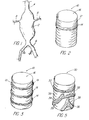
- FIGURES 2 and 3 are isometric views of first and second embodiments of the present invention having a stent and a single annular inflatable band or multiple annular bands;
- FIGURES 4A and 4B are isometric views of a third embodiment before and after balloon inflation, where the balloons have a nonannular pattern such as spiral;
- FIGURE 5 is similar to FIGS. 4A and 4B of a fourth embodiment where the balloons have an asymmetric pattern;
- FIGURE 6 is a fifth embodiment of the present invention having a first annular inflatable portion at one end to seal outwardly against the vessel wall, and a second annular inflatable portion proximate the other end that would expand to fill the aneurysm sac;
- FIGURES 7 and 8 are sixth and seventh embodiments of the present invention having a Z-type stent or a spiral stent, respectively, and multiple branches with stent balloons;
- FIGURE 9 is an eighth embodiment having a stent that is adapted to be secured at the entrance to a branch artery;
- FIGURE 10 is a ninth embodiment illustrating a main stent with two branch stents extending radially outwardly therefrom, each having two annular inflatable portions, with the main stent also having two annular inflatable portions positioned on either side of the pair of branch stents;
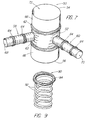
- FIGURE 11 is an isometric view illustrating an embodiment of the present invention in situ in the aorta extending from an end of an abdominal aortic stent graft proximally past entrances to opposed renal arteries, and having an inflatable portion sealing against the vessel wall to seal the aneurysm;
- FIGURES 13 and 14 illustrate the placement of the proximal neck device of FIG. 1 1 , with the device initially placed at a minimal-sized infrarenal neck, and subsequently inflated in FIG. 12 to approximate an extended proximal aneurysm neck to facilitate placement of the abdominal aortic stent graft;
- FIGURE 14 is an isometric view of the device of the present invention utilized with an elongate stent graft for an aneurysm that extends past the renal arteries, with devices of the present invention extending radially outwardly from the stent graft to enter the branch arteries to maintain the patency thereof, while the elongate stent graft proximal end is secured to the vessel wall above the branch arteries;
- FIGURE 15 is an isometric view similar to FIG. 14 with the several inflatable portions of a stent graft assembly having respective lumens for separate selective inflation thereof; and
- FIGURES 16 to 19 are end views of an additional embodiments of the present invention that comprise occluders.
-
- In FIG. 1 is illustrated an aneurysm 2 of the
aorta 4 in the abdomen of a patient proximal to the iliac arteries 6, with therenal arteries 8 spaced proximally thereof. Stent grafts presently known, such as that disclosed in PCT Publication No. WO 98/53761, could not generally be utilized at least alone to treat such an aneurysm 2 since the wall of the stent graft main lumen formed by graft material would traverse the branch arteries thereby occluding flow, as the proximal end of the stent graft would have to be secured to healthy vessel wall spaced from the aneurysm to thereby seal off the aneurysm proximally, with the legs of the stent graft being secured to the iliac artery walls below the aneurysm, to seal the aneurysm distally. - The
endovascular device 10 of the present invention, as shown in FIG. 2, includes at least onestent 12 and at least oneinflatable portion 14, with alumen 16 extending axially therethrough. In most Figures, the stent frame structure is depicted generally as a cylindrical grid having struts that are oriented at an angle with respect to the longitudinal axis of the lumen, and the inflatable portions may be affixed to surfaces of the grid such as by adhesive bonding. - In FIG. 3,
device 10 utilizes second and third annularinflatable portions inflatable portion 14. With this device, the first and secondinflatable portions stent 10, while the thirdinflatable portion 20 could be a sealing balloon that surrounds the stent and expand to form a seal against the wall of the aorta surrounding the periphery to the entrance to a branch artery (as illustrated in FIG. 11). The several inflatable portions may have separate discrete inflation lumens (see FIG. 13). - The
device 20 of FIG. 4A includes several inflatable portions or members or balloons 22,24,26 that extend in spiral fashion about the stent outer surface spaced apart when not inflated, which would allow instrumentation to extend through and between the struts of the stent andspacings 28 between the deflated members. In FIG. 4B, the members are shown inflated as they would be within a vessel to press against the vessel walls, and would also press against each other to define a seal between the stent and the vessel wall. - In FIG. 5, several inflatable members or balloons 32,34,36 of
device 30 are shown in an asymmetric pattern selected to complement certain vasculatory anatomy such that spaces are defined between the balloons when they are deflated but which can seal against the vessel wall and each other after inflation except in thelarger spacings 38 between balloons that may align with branch vessel entrances to permit blood flow thereinto. -
Device 40 of FIG. 6 includes a firstinflatable portion 42 at a first end ofstent graft 44, to establish a seal against healthy vessel wall adjacent the entrance to an aneurysm. A secondinflatable portion 46 is larger, preferably thin-walled, for filling the aneurysm sac upon inflation thereof. - In FIG. 7 is illustrated another
embodiment 50 of the endovascular device of the present invention. Amain stent 52 includes afirst end 54 and asecond end 56. Second andthird stents main stent 52 remote from ends 54,56 to extend into and along branch arteries.Main stent 52 includes at least twoinflatable portions 62 as shown, and each of second andthird stents inflatable portions 64.Graft material 66 is shown surrounding portions ofmain stent 52 adjacent to first and second ends 54,56; use ofgraft material 66 is optional, however, and may be combined with balloons.Lumens third stents central lumen 72 ofmain stent 52. Second andthird stents main stent 52 through openings between the struts thereof. Second andthird stents - FIGS. 8 to 10 illustrate types of stents useful with the present invention. In FIG. 8,
stent 80 illustrates both anannular member 82 at one end, and another portion of the stent that is shown to be completely or partially affixed withmembers 84 in a pattern identical to the struts 86 of the stent.Stent 90 of FIG. 9 has spiral struts 92 and an associatedmember 94 oriented to expand against the outer diameter; this may add flexibility and improved sealing to the system. - In FIG. 10, stent 100 is a button stent that has a greater expansile capacity at
proximal end 102 withstrut portions 104 that are expandable to deflect radially outwardly and rotate backwardly to become engaged with the vessel wall or with struts of anotherstent 106 surrounding the periphery of the entrance of abranch artery 108 to prevent movement of the stent into thebranch artery 108; theinflatable portion 110 seals the branch artery from the aneurysm in whichstent 106 is affixed to provide a sealing mechanism so that a stent assembly may be defined for multiple "branches".Strut portions 104 preferably are of the type to self expand upon release from within a retractable sheath (not shown) but may be balloon expandable and shapable by altering the balloon shape and expansion/inflation characteristics. - FIGS. 11 to 13 depict placement of an endovascular device of the present invention in situ within an abdominal aortic aneurysm. In FIG. 11, a
device 150 of the present invention is used in conjunction with an abdominalaortic stent graft 152 of conventional design, for use in treating ananeurysm 154 having aninfrarenal neck 156 of minimal length adjacent to branch or renal arteries 158,160.Device 150 includes astent 162 initially positioned (FIG. 12) to traverse the entrances 164,166 of renal arteries 158,160, with the stent being free of graft material and thereby not occluding the renal arteries.Device 150 may be of the type that is self-expandable, or is expandable by use of a stent-expanding balloon. Annularinflatable portion 168 ofdevice 150 surroundsstent 162 and is located immediately adjacent to entrances 164,166 of renal arteries 158,160 and is shown inflated (FIG. 1 2) to seal against vessel wall to close off theentrance 156 to theaneurysm 154. Whendevice 150 is so placed andinflatable portion 168 has been inflated,device 150 approximates an aneurysmal neck of substantial length enabling the use of a conventional stent graft. The proximal end of thestent graft 152 is insertable into the lumen ofdevice 150 and attachable thereto following the same procedures as if it were being attached to the vessel wall. Optionally, the device may be affixed about a distal end of the stent graft prior to placement, to simplify the procedure. - In FIG. 14, an
elongate stent graft 200 extends from legs 202,204 to aproximal end 206, and positioned in and alonganeurysm 208 from iliac arteries 210,212 tohealthy vessel wall 214 adjacent toentrance 216.Aneurysm 208 is of the type to encompass the entrances to branch arteries, such as renal arteries or superior mesenteric arteries (SMA), which of course can not be allowed to become occluded or blocked by the stent graft. - FIG. 15 demonstrates potential pre-deployment access or
inflation lumens 250 for theinflatable sealing members 252 each of thebranch segments 254 of astent graft assembly 256. - The present invention also is useful in defining a
detachable occluder 300. As seen in FIGS. 16 and 17, the inflatable member is mounted along the inside of thestent 302 and is uninflated when the stent is being placed; the member may be annular 304, or may comprise opposing portions 306,306. Then, as shown in FIGS. 18 and 19, the inflatable portion(s) is (are) expanded by a diffusable solution, not only to fully expand the stent but also to completely traverse thelumen 308 of the stent and thereby completely occlude the artery. The inflatable portion(s) may be the length of the stent, and may be from 10 to 40 mm in length. After inflation, the inflation mechanism may be detached. - One stent useful with the present invention is the Z-STENT™, sold by Cook Incorporated of Bloomington, Indiana. A similar stent is disclosed in U.S. Patent No. 4,580,568. Another stent is disclosed in U.S. Patent No. 5,015,253 and having a spiral strut configuration.
- A stent useful with the present invention could comprise stainless steel, Nitinol, titanium alloy, tantalum or Elgiloy, among others. The stents could be lined with thin-walled material that is possibly biodegradable or dissolvable to prevent balloon intrusion into the lumen of the stent. The balloons defining the inflatable portions could comprise latex, silicone rubber, PET (polyethylene terephthalate) or nylon and so forth, and could be impermeable or semipermeable. Attachment of the inflatable member to the stent may be by use of an appropriate adhesive or bonding agent. The luminal inflation mechanism could be a single lumen connected to each inflatable portion, or a plurality of discrete lumens that are separately inflatable for selective and/or sequential inflation thereof. The filling mechanism can involve a series of detachable lumens that are detached by a trigger mechanism at the delivery device level, a sheath that is advanced over the balloon lumen to separate the devices, or a pressure type valve. In addition, the lumens of the balloons can be joined, in which case all the balloons can be filled off a single lumen, or there can be discrete filling chambers with separate lumens, involving separate disconnect mechanisms.
- The substance used to inflate the lumen can vary from standard saline or air, to a silicone based substance or something that will solidify over time. The mechanism of this can occur by coupling a balloon material that is selectively permeable with an inflation medium that solidifies with the diffusion of the substance to which the balloon material is permeable. This would allow the chemical constitution of the balloon contacts to vary, thus altering the physical properties over time.
- Another approach would be to provide a substance within the deflated member or balloon, that expands when exposed to ultraviolet or visible light that activates a catalyst within the substance, whereby the substance foams up to inflate the inflatable member; in such a case no inflation lumen is necessary, and the light energy can be transmitted by an optical fiber within the catheter such as being secured to the wire guide.
- An inflation lumen monitoring device (such as a wire or module that measures pressure) can be placed within, or just outside a balloon lumen such that when the balloon is inflated the device can register the pressure transmitted to the balloon lumen or the wall of the aneurysm/artery. The sensor will have to have a means of transmitting the data to a monitor placed on the patient in the proximity of the device or over the phone line. -- as some pacemakers do.
- The inflated member can either be big and bulky to fill the aneurysmal sac or, more likely, have properties to be sandwiched between stents, in such a way so that it becomes a "lining" like graft material over the lumen or outer stent scaffold upon inflation.
- Additionally, an inflatable member may be utilized within the stent lumen and sufficiently affixed thereto along the inner surface when the stent is in its reduced dimension state, to be utilized for expansion of the stent upon deployment within a vessel whereafter the inflatable member may thereafter be deflated and removed.
Claims (11)
- Medical apparatus comprising a structure with at least one stent (10, 20, 30, 40, 50, 58, 60, 80, 90, 100, 150, 254, 256) having a lumen therethrough and being compressible to a relatively small dimension for placement into a delivery device for delivery to a deployment site in a vessel of a patient and for expansion to a relatively large dimension, and an expandable arrangement (14, 18, 19, 22, 24, 26, 32, 34, 36, 42, 46, 82, 84, 94) secured to said structure to expand so that the arrangement provides a seat between the said one stent and the wall of the vessel at the deployment site, characterized in that the expandable arrangement comprises a plurality of separate expandable members which when unexpanded are spaced apart but sufficienly closely so that, when expanded, abut one another to form the said seal.
- Medical apparatus according to claim 1, for treating a patient with an aortic aneurysm extending across a region embracing the renal arteries, said apparatus when deployed, serving to extend from upstream of the said region to a position downstream of the renal arteries, characterized in that the said expandable members (14, 18, 19, 22, 24, 26, 32, 34, 36, 42, 46, 82, 84, 94) are secured to said at least one stent and are expandable in an outward direction from the stent to provide a seal between the vessel in the region of the downstream position and the stent.
- Apparatus according to claim 1 or 2 wherein said expandable members (14, 18, 19, 42, 46, 82, 94) are disposed circumferentiatly around said at least one stent.
- Apparatus according to claim 3 wherein said expandable members (22, 24, 26, 84) are disposed in respective spiral configurations for example in parallel, around said at least one stent.
- Apparatus according to any one of the preceding claims, wherein another medical device extends radially outwardly through said one stent and between selected adjacent ones of said members such that said members are adapted to press against said another medical device or against each other or both, upon expansion.
- Apparatus according to any one of the preceding claims, wherein said stent (90) includes a plurality of spiral struts with several of said spiral struts having respective said expandable members affixed thereto.
- Apparatus according to any one of the preceding claims, wherein said stent further includes graft material affixed thereto.
- Apparatus according to claim 7, wherein certain parts of the said at least one stent are free of graft material whereby body fluid may pass through said certain parts to other vessels or said arteries.
- Apparatus according to claim 1 or 2, wherein at least a second stent (254) extends outwardly from an outer surface of said stent (256) to an end that is within a branch vessel upon deployment, said stem including a pair of annular ones of said expandable members affixed to said outer surface of said stent on distal and proximal sides of said second stent to seal said stent against said vessel wall distally and proximately of said branch vessel.
- Apparatus according to claim 9, wherein said second stent (254) includes at least one expandable member affixed thereto proximate said end of said second stent, and/or wherein a third stent extends outwardly from said outer surface of said stent between said pair of annular ones of said expandable members, to a respective end that is within another branch vessel upon deployment.
- Apparatus according to claim 1 or 2 wherein the plurality of said expandable members (32, 34, 36) are arranged in an asymmetric pattern selected to complement vascular anatomy and to define at least one space between said plurality of expandable members upon their expansion to permit blood flow through said at least one space.
Applications Claiming Priority (3)
| Application Number | Priority Date | Filing Date | Title |
|---|---|---|---|
| US18658600P | 2000-03-03 | 2000-03-03 | |
| US186586P | 2000-03-03 | ||
| PCT/US2001/006764 WO2001066038A2 (en) | 2000-03-03 | 2001-03-02 | Endovascular device having a stent |
Publications (2)
| Publication Number | Publication Date |
|---|---|
| EP1259192A2 EP1259192A2 (en) | 2002-11-27 |
| EP1259192B1 true EP1259192B1 (en) | 2003-12-10 |
Family
ID=22685520
Family Applications (1)
| Application Number | Title | Priority Date | Filing Date |
|---|---|---|---|
| EP01918303A Expired - Lifetime EP1259192B1 (en) | 2000-03-03 | 2001-03-02 | Endovascular device having a stent |
Country Status (12)
| Country | Link |
|---|---|
| US (1) | US6827735B2 (en) |
| EP (1) | EP1259192B1 (en) |
| JP (1) | JP4914957B2 (en) |
| KR (1) | KR20020082861A (en) |
| AT (1) | ATE255860T1 (en) |
| AU (1) | AU769900B2 (en) |
| CA (1) | CA2397980C (en) |
| DE (1) | DE60101455T2 (en) |
| DK (1) | DK1259192T3 (en) |
| ES (1) | ES2211791T3 (en) |
| PT (1) | PT1259192E (en) |
| WO (1) | WO2001066038A2 (en) |
Families Citing this family (227)
| Publication number | Priority date | Publication date | Assignee | Title |
|---|---|---|---|---|
| US7238197B2 (en) | 2000-05-30 | 2007-07-03 | Devax, Inc. | Endoprosthesis deployment system for treating vascular bifurcations |
| US6666883B1 (en) | 1996-06-06 | 2003-12-23 | Jacques Seguin | Endoprosthesis for vascular bifurcation |
| US8728143B2 (en) | 1996-06-06 | 2014-05-20 | Biosensors International Group, Ltd. | Endoprosthesis deployment system for treating vascular bifurcations |
| US7686846B2 (en) | 1996-06-06 | 2010-03-30 | Devax, Inc. | Bifurcation stent and method of positioning in a body lumen |
| US6599316B2 (en) | 1996-11-04 | 2003-07-29 | Advanced Stent Technologies, Inc. | Extendible stent apparatus |
| US7341598B2 (en) | 1999-01-13 | 2008-03-11 | Boston Scientific Scimed, Inc. | Stent with protruding branch portion for bifurcated vessels |
| US6835203B1 (en) | 1996-11-04 | 2004-12-28 | Advanced Stent Technologies, Inc. | Extendible stent apparatus |
| US7591846B2 (en) | 1996-11-04 | 2009-09-22 | Boston Scientific Scimed, Inc. | Methods for deploying stents in bifurcations |
| US8211167B2 (en) | 1999-12-06 | 2012-07-03 | Boston Scientific Scimed, Inc. | Method of using a catheter with attached flexible side sheath |
| US6692483B2 (en) | 1996-11-04 | 2004-02-17 | Advanced Stent Technologies, Inc. | Catheter with attached flexible side sheath |
| US6325826B1 (en) | 1998-01-14 | 2001-12-04 | Advanced Stent Technologies, Inc. | Extendible stent apparatus |
| US6395019B2 (en) | 1998-02-09 | 2002-05-28 | Trivascular, Inc. | Endovascular graft |
| US7335220B2 (en) | 2004-11-05 | 2008-02-26 | Access Closure, Inc. | Apparatus and methods for sealing a vascular puncture |
| US7655030B2 (en) | 2003-07-18 | 2010-02-02 | Boston Scientific Scimed, Inc. | Catheter balloon systems and methods |
| US8257425B2 (en) | 1999-01-13 | 2012-09-04 | Boston Scientific Scimed, Inc. | Stent with protruding branch portion for bifurcated vessels |
| US6454799B1 (en) | 2000-04-06 | 2002-09-24 | Edwards Lifesciences Corporation | Minimally-invasive heart valves and methods of use |
| CA2419811A1 (en) | 2000-08-18 | 2002-02-28 | Atritech, Inc. | Expandable implant devices for filtering blood flow from atrial appendages |
| US6942692B2 (en) * | 2000-11-16 | 2005-09-13 | Cordis Corporation | Supra-renal prosthesis and renal artery bypass |
| US20030097169A1 (en) | 2001-02-26 | 2003-05-22 | Brucker Gregory G. | Bifurcated stent and delivery system |
| WO2002076346A1 (en) * | 2001-03-23 | 2002-10-03 | Hassan Tehrani | Branched aortic arch stent graft |
| US8617231B2 (en) | 2001-05-18 | 2013-12-31 | Boston Scientific Scimed, Inc. | Dual guidewire exchange catheter system |
| GB0114918D0 (en) * | 2001-06-19 | 2001-08-08 | Vortex Innovation Ltd | Devices for repairing aneurysms |
| US7578841B2 (en) | 2001-09-24 | 2009-08-25 | Boston Scientific Scimed, Inc. | Stent with protruding branch portion for bifurcated vessels |
| JP2005505345A (en) * | 2001-10-09 | 2005-02-24 | ウイルアム クック,ユーロップ エイピーエス | Kanyo lestent |
| US7033389B2 (en) | 2001-10-16 | 2006-04-25 | Scimed Life Systems, Inc. | Tubular prosthesis for external agent delivery |
| US7192441B2 (en) * | 2001-10-16 | 2007-03-20 | Scimed Life Systems, Inc. | Aortic artery aneurysm endovascular prosthesis |
| AUPR847201A0 (en) * | 2001-10-26 | 2001-11-15 | Cook Incorporated | Endoluminal graft |
| US7209788B2 (en) | 2001-10-29 | 2007-04-24 | Duke University | Closed loop brain machine interface |
| US20060292206A1 (en) | 2001-11-26 | 2006-12-28 | Kim Steven W | Devices and methods for treatment of vascular aneurysms |
| US7147661B2 (en) | 2001-12-20 | 2006-12-12 | Boston Scientific Santa Rosa Corp. | Radially expandable stent |
| US7125464B2 (en) | 2001-12-20 | 2006-10-24 | Boston Scientific Santa Rosa Corp. | Method for manufacturing an endovascular graft section |
| AUPR969201A0 (en) | 2001-12-20 | 2002-01-24 | White, Geoffrey H. | A device for use in intraluminal grafting |
| US7399313B2 (en) * | 2002-06-07 | 2008-07-15 | Brown Peter S | Endovascular graft with separable sensors |
| US7025778B2 (en) * | 2002-06-07 | 2006-04-11 | Endovascular Technologies, Inc. | Endovascular graft with pressure, temperature, flow and voltage sensors |
| US6858038B2 (en) * | 2002-06-21 | 2005-02-22 | Richard R. Heuser | Stent system |
| AU2003272682C1 (en) | 2002-09-20 | 2009-07-16 | Nellix, Inc. | Stent-graft with positioning anchor |
| AU2002356575B2 (en) | 2002-11-08 | 2009-07-16 | Jean-Claude Laborde | Endoprosthesis for vascular bifurcation |
| US7481821B2 (en) | 2002-11-12 | 2009-01-27 | Thomas J. Fogarty | Embolization device and a method of using the same |
| US7407509B2 (en) | 2003-01-14 | 2008-08-05 | The Cleveland Clinic Foundation | Branched vessel endoluminal device with fenestration |
| US7105020B2 (en) * | 2003-01-14 | 2006-09-12 | The Cleveland Clinic Foundation | Branched vessel endoluminal device |
| US9125733B2 (en) | 2003-01-14 | 2015-09-08 | The Cleveland Clinic Foundation | Branched vessel endoluminal device |
| US20040260382A1 (en) | 2003-02-12 | 2004-12-23 | Fogarty Thomas J. | Intravascular implants and methods of using the same |
| US20040254627A1 (en) * | 2003-04-04 | 2004-12-16 | Thompson Paul J. | Stent with end adapted for flaring |
| US20050015110A1 (en) * | 2003-07-18 | 2005-01-20 | Fogarty Thomas J. | Embolization device and a method of using the same |
| US8298280B2 (en) | 2003-08-21 | 2012-10-30 | Boston Scientific Scimed, Inc. | Stent with protruding branch portion for bifurcated vessels |
| US9078780B2 (en) * | 2003-11-08 | 2015-07-14 | Cook Medical Technologies Llc | Balloon flareable branch vessel prosthesis and method |
| US7344557B2 (en) | 2003-11-12 | 2008-03-18 | Advanced Stent Technologies, Inc. | Catheter balloon systems and methods |
| EP1696828B1 (en) * | 2003-12-17 | 2010-08-25 | Cook Incorporated | Interconnected leg extensions for an endoluminal prostehsis |
| US11278398B2 (en) | 2003-12-23 | 2022-03-22 | Boston Scientific Scimed, Inc. | Methods and apparatus for endovascular heart valve replacement comprising tissue grasping elements |
| US8840663B2 (en) | 2003-12-23 | 2014-09-23 | Sadra Medical, Inc. | Repositionable heart valve method |
| US20120041550A1 (en) | 2003-12-23 | 2012-02-16 | Sadra Medical, Inc. | Methods and Apparatus for Endovascular Heart Valve Replacement Comprising Tissue Grasping Elements |
| US8343213B2 (en) | 2003-12-23 | 2013-01-01 | Sadra Medical, Inc. | Leaflet engagement elements and methods for use thereof |
| US7381219B2 (en) | 2003-12-23 | 2008-06-03 | Sadra Medical, Inc. | Low profile heart valve and delivery system |
| US8052749B2 (en) | 2003-12-23 | 2011-11-08 | Sadra Medical, Inc. | Methods and apparatus for endovascular heart valve replacement comprising tissue grasping elements |
| US7988724B2 (en) | 2003-12-23 | 2011-08-02 | Sadra Medical, Inc. | Systems and methods for delivering a medical implant |
| EP2745805B2 (en) | 2003-12-23 | 2022-05-18 | Boston Scientific Scimed, Inc. | Repositionable heart valve |
| PT2926766T (en) | 2003-12-23 | 2017-06-02 | Boston Scient Scimed Inc | Repositionable heart valve |
| US7803178B2 (en) | 2004-01-30 | 2010-09-28 | Trivascular, Inc. | Inflatable porous implants and methods for drug delivery |
| US20050228484A1 (en) * | 2004-03-11 | 2005-10-13 | Trivascular, Inc. | Modular endovascular graft |
| US8007528B2 (en) | 2004-03-17 | 2011-08-30 | Boston Scientific Scimed, Inc. | Bifurcated stent |
| US7799041B2 (en) * | 2004-03-23 | 2010-09-21 | Correx, Inc. | Apparatus and method for forming a hole in a hollow organ |
| EP1761202A4 (en) | 2004-03-23 | 2012-06-13 | Correx Inc | Apparatus and method for connecting a conduit to a hollow organ |
| US7674284B2 (en) * | 2004-03-31 | 2010-03-09 | Cook Incorporated | Endoluminal graft |
| US9358141B2 (en) | 2004-03-31 | 2016-06-07 | Cook Medical Technologies Llc | Stent deployment device |
| US8048140B2 (en) | 2004-03-31 | 2011-11-01 | Cook Medical Technologies Llc | Fenestrated intraluminal stent system |
| US7435257B2 (en) | 2004-05-05 | 2008-10-14 | Direct Flow Medical, Inc. | Methods of cardiac valve replacement using nonstented prosthetic valve |
| CA2565106C (en) | 2004-05-25 | 2013-11-05 | Chestnut Medical Technologies, Inc. | Flexible vascular occluding device |
| US8617234B2 (en) | 2004-05-25 | 2013-12-31 | Covidien Lp | Flexible vascular occluding device |
| US20060206200A1 (en) | 2004-05-25 | 2006-09-14 | Chestnut Medical Technologies, Inc. | Flexible vascular occluding device |
| SG175723A1 (en) | 2004-05-25 | 2011-12-29 | Tyco Healthcare | Vascular stenting for aneurysms |
| US8628564B2 (en) | 2004-05-25 | 2014-01-14 | Covidien Lp | Methods and apparatus for luminal stenting |
| US8048145B2 (en) | 2004-07-22 | 2011-11-01 | Endologix, Inc. | Graft systems having filling structures supported by scaffolds and methods for their use |
| EP1778131B1 (en) * | 2004-07-22 | 2012-01-11 | Nellix, Inc. | Systems for endovascular aneurysm treatment |
| US20060074481A1 (en) * | 2004-10-04 | 2006-04-06 | Gil Vardi | Graft including expandable cuff |
| US20070179600A1 (en) * | 2004-10-04 | 2007-08-02 | Gil Vardi | Stent graft including expandable cuff |
| US9427340B2 (en) | 2004-12-14 | 2016-08-30 | Boston Scientific Scimed, Inc. | Stent with protruding branch portion for bifurcated vessels |
| US8277465B2 (en) * | 2004-12-15 | 2012-10-02 | Correx, Inc. | Apparatus and method for connecting a conduit to a hollow vessel |
| US7588596B2 (en) * | 2004-12-29 | 2009-09-15 | Scimed Life Systems, Inc. | Endoluminal prosthesis adapted to resist migration and method of deploying the same |
| KR100614654B1 (en) * | 2005-01-04 | 2006-08-22 | 삼성전자주식회사 | RF transmitter for efficiently compensating output power variation due to temperature and process |
| US8287583B2 (en) * | 2005-01-10 | 2012-10-16 | Taheri Laduca Llc | Apparatus and method for deploying an implantable device within the body |
| US8128680B2 (en) * | 2005-01-10 | 2012-03-06 | Taheri Laduca Llc | Apparatus and method for deploying an implantable device within the body |
| US20060155366A1 (en) * | 2005-01-10 | 2006-07-13 | Laduca Robert | Apparatus and method for deploying an implantable device within the body |
| DE102005003632A1 (en) | 2005-01-20 | 2006-08-17 | Fraunhofer-Gesellschaft zur Förderung der angewandten Forschung e.V. | Catheter for the transvascular implantation of heart valve prostheses |
| US20060222596A1 (en) | 2005-04-01 | 2006-10-05 | Trivascular, Inc. | Non-degradable, low swelling, water soluble radiopaque hydrogel polymer |
| WO2006116725A2 (en) | 2005-04-28 | 2006-11-02 | Nellix, Inc. | Graft systems having filling structures supported by scaffolds and methods for their use |
| US8317855B2 (en) | 2005-05-26 | 2012-11-27 | Boston Scientific Scimed, Inc. | Crimpable and expandable side branch cell |
| US8480728B2 (en) | 2005-05-26 | 2013-07-09 | Boston Scientific Scimed, Inc. | Stent side branch deployment initiation geometry |
| JP5119148B2 (en) | 2005-06-07 | 2013-01-16 | ダイレクト フロウ メディカル、 インク. | Stentless aortic valve replacement with high radial strength |
| EP1903985A4 (en) * | 2005-07-07 | 2010-04-28 | Nellix Inc | Systems and methods for endovascular aneurysm treatment |
| US7955374B2 (en) * | 2005-09-02 | 2011-06-07 | Medtronic Vascular, Inc. | Modular branch vessel stent-graft assembly |
| US7731741B2 (en) | 2005-09-08 | 2010-06-08 | Boston Scientific Scimed, Inc. | Inflatable bifurcation stent |
| US8043366B2 (en) | 2005-09-08 | 2011-10-25 | Boston Scientific Scimed, Inc. | Overlapping stent |
| US8038706B2 (en) | 2005-09-08 | 2011-10-18 | Boston Scientific Scimed, Inc. | Crown stent assembly |
| US8140170B2 (en) | 2005-09-12 | 2012-03-20 | The Cleveland Clinic Foundation | Method and apparatus for renal neuromodulation |
| US7569071B2 (en) | 2005-09-21 | 2009-08-04 | Boston Scientific Scimed, Inc. | Venous valve, system, and method with sinus pocket |
| US20070112418A1 (en) | 2005-11-14 | 2007-05-17 | Boston Scientific Scimed, Inc. | Stent with spiral side-branch support designs |
| US8435284B2 (en) | 2005-12-14 | 2013-05-07 | Boston Scientific Scimed, Inc. | Telescoping bifurcated stent |
| US8343211B2 (en) | 2005-12-14 | 2013-01-01 | Boston Scientific Scimed, Inc. | Connectors for bifurcated stent |
| US7540881B2 (en) | 2005-12-22 | 2009-06-02 | Boston Scientific Scimed, Inc. | Bifurcation stent pattern |
| US20070213813A1 (en) | 2005-12-22 | 2007-09-13 | Symetis Sa | Stent-valves for valve replacement and associated methods and systems for surgery |
| WO2007100556A1 (en) | 2006-02-22 | 2007-09-07 | Ev3 Inc. | Embolic protection systems having radiopaque filter mesh |
| US8821561B2 (en) | 2006-02-22 | 2014-09-02 | Boston Scientific Scimed, Inc. | Marker arrangement for bifurcation catheter |
| US7833264B2 (en) | 2006-03-06 | 2010-11-16 | Boston Scientific Scimed, Inc. | Bifurcated stent |
| US8298278B2 (en) | 2006-03-07 | 2012-10-30 | Boston Scientific Scimed, Inc. | Bifurcated stent with improvement securement |
| US8795709B2 (en) | 2006-03-29 | 2014-08-05 | Incept Llc | Superabsorbent, freeze dried hydrogels for medical applications |
| US9707113B2 (en) | 2006-04-19 | 2017-07-18 | Cook Medical Technologies Llc | Twin bifurcated stent graft |
| US7790273B2 (en) * | 2006-05-24 | 2010-09-07 | Nellix, Inc. | Material for creating multi-layered films and methods for making the same |
| US7872068B2 (en) * | 2006-05-30 | 2011-01-18 | Incept Llc | Materials formable in situ within a medical device |
| WO2008002441A2 (en) | 2006-06-23 | 2008-01-03 | Boston Scientific Limited | Bifurcated stent with twisted hinges |
| US8216297B2 (en) | 2006-08-14 | 2012-07-10 | Trivascular, Inc. | Dual chamber cuff structure |
| US8216267B2 (en) | 2006-09-12 | 2012-07-10 | Boston Scientific Scimed, Inc. | Multilayer balloon for bifurcated stent delivery and methods of making and using the same |
| US7951191B2 (en) | 2006-10-10 | 2011-05-31 | Boston Scientific Scimed, Inc. | Bifurcated stent with entire circumferential petal |
| US8133213B2 (en) | 2006-10-19 | 2012-03-13 | Direct Flow Medical, Inc. | Catheter guidance through a calcified aortic valve |
| US7935144B2 (en) | 2006-10-19 | 2011-05-03 | Direct Flow Medical, Inc. | Profile reduction of valve implant |
| US8206429B2 (en) | 2006-11-02 | 2012-06-26 | Boston Scientific Scimed, Inc. | Adjustable bifurcation catheter incorporating electroactive polymer and methods of making and using the same |
| US7842082B2 (en) | 2006-11-16 | 2010-11-30 | Boston Scientific Scimed, Inc. | Bifurcated stent |
| US7959668B2 (en) | 2007-01-16 | 2011-06-14 | Boston Scientific Scimed, Inc. | Bifurcated stent |
| US20080188923A1 (en) * | 2007-02-01 | 2008-08-07 | Jack Fa-De Chu | Endovascular devices to protect aneurysmal wall |
| EP2114303A4 (en) | 2007-02-09 | 2012-08-08 | Taheri Laduca Llc | Vascular implants and methods of fabricating the same |
| BRPI0807261B8 (en) | 2007-02-09 | 2021-06-22 | Taheri Laduca Llc | stent-loaded catheter sets |
| US8118861B2 (en) | 2007-03-28 | 2012-02-21 | Boston Scientific Scimed, Inc. | Bifurcation stent and balloon assemblies |
| US8647376B2 (en) | 2007-03-30 | 2014-02-11 | Boston Scientific Scimed, Inc. | Balloon fold design for deployment of bifurcated stent petal architecture |
| US7896915B2 (en) | 2007-04-13 | 2011-03-01 | Jenavalve Technology, Inc. | Medical device for treating a heart valve insufficiency |
| US20090030502A1 (en) * | 2007-07-26 | 2009-01-29 | Jichao Sun | Socket For Fenestrated Tubular Prosthesis |
| US8486134B2 (en) | 2007-08-01 | 2013-07-16 | Boston Scientific Scimed, Inc. | Bifurcation treatment system and methods |
| US20090088836A1 (en) | 2007-08-23 | 2009-04-02 | Direct Flow Medical, Inc. | Translumenally implantable heart valve with formed in place support |
| US7959669B2 (en) | 2007-09-12 | 2011-06-14 | Boston Scientific Scimed, Inc. | Bifurcated stent with open ended side branch support |
| US8066755B2 (en) | 2007-09-26 | 2011-11-29 | Trivascular, Inc. | System and method of pivoted stent deployment |
| US8226701B2 (en) | 2007-09-26 | 2012-07-24 | Trivascular, Inc. | Stent and delivery system for deployment thereof |
| US8663309B2 (en) | 2007-09-26 | 2014-03-04 | Trivascular, Inc. | Asymmetric stent apparatus and method |
| EP3443938B1 (en) | 2007-09-26 | 2024-01-24 | St. Jude Medical, LLC | Collapsible prosthetic heart valves |
| US9532868B2 (en) | 2007-09-28 | 2017-01-03 | St. Jude Medical, Inc. | Collapsible-expandable prosthetic heart valves with structures for clamping native tissue |
| JP2010540190A (en) | 2007-10-04 | 2010-12-24 | トリバスキュラー・インコーポレイテッド | Modular vascular graft for low profile transdermal delivery |
| US8328861B2 (en) | 2007-11-16 | 2012-12-11 | Trivascular, Inc. | Delivery system and method for bifurcated graft |
| US8083789B2 (en) | 2007-11-16 | 2011-12-27 | Trivascular, Inc. | Securement assembly and method for expandable endovascular device |
| US7833266B2 (en) | 2007-11-28 | 2010-11-16 | Boston Scientific Scimed, Inc. | Bifurcated stent with drug wells for specific ostial, carina, and side branch treatment |
| US8277501B2 (en) | 2007-12-21 | 2012-10-02 | Boston Scientific Scimed, Inc. | Bi-stable bifurcated stent petal geometry |
| US8002816B2 (en) * | 2007-12-21 | 2011-08-23 | Cleveland Clinic Foundation | Prosthesis for implantation in aorta and method of using same |
| US20090164001A1 (en) * | 2007-12-21 | 2009-06-25 | Biggs David P | Socket For Fenestrated Tubular Prosthesis |
| EP2242456A2 (en) | 2007-12-31 | 2010-10-27 | Boston Scientific Scimed, Inc. | Bifurcation stent delivery system and methods |
| US7862538B2 (en) | 2008-02-04 | 2011-01-04 | Incept Llc | Surgical delivery system for medical sealant |
| CA2714570A1 (en) * | 2008-02-13 | 2009-08-20 | Nellix, Inc. | Graft endoframe having axially variable characteristics |
| US8221494B2 (en) | 2008-02-22 | 2012-07-17 | Endologix, Inc. | Apparatus and method of placement of a graft or graft system |
| ES2903231T3 (en) | 2008-02-26 | 2022-03-31 | Jenavalve Tech Inc | Stent for positioning and anchoring a valve prosthesis at an implantation site in a patient's heart |
| US9044318B2 (en) | 2008-02-26 | 2015-06-02 | Jenavalve Technology Gmbh | Stent for the positioning and anchoring of a valvular prosthesis |
| JP5663471B2 (en) | 2008-04-25 | 2015-02-04 | ネリックス・インコーポレーテッド | Stent / graft delivery system |
| US8932340B2 (en) | 2008-05-29 | 2015-01-13 | Boston Scientific Scimed, Inc. | Bifurcated stent and delivery system |
| US8377108B2 (en) | 2008-06-02 | 2013-02-19 | Boston Scientific Scimed, Inc. | Staggered two balloon bifurcation catheter assembly and methods |
| JP2011522615A (en) | 2008-06-04 | 2011-08-04 | ネリックス・インコーポレーテッド | Sealing device and method of use |
| JP5662310B2 (en) | 2008-06-05 | 2015-01-28 | ボストン サイエンティフィック サイムド,インコーポレイテッドBoston Scientific Scimed,Inc. | Shrinkable branch device and method of manufacturing the same |
| EP2299945B1 (en) | 2008-06-05 | 2016-03-23 | Boston Scientific Scimed, Inc. | Balloon bifurcated lumen treatment |
| LT3476367T (en) | 2008-06-06 | 2020-01-27 | Edwards Lifesciences Corporation | Low profile transcatheter heart valve |
| US8454679B2 (en) * | 2008-07-10 | 2013-06-04 | Atrial Systems, Llc | Endovascular conduit device for increasing safety of cardiac lead extraction and other vascular procedures |
| US8454680B2 (en) * | 2008-07-10 | 2013-06-04 | Atrial Systems, Llc | Endovascular conduit device with low profile occlusion members |
| ES2616743T3 (en) | 2008-07-15 | 2017-06-14 | St. Jude Medical, Llc | Collapsible and re-expandable prosthetic heart valve sleeve designs and complementary technological applications |
| US8353943B2 (en) * | 2008-08-29 | 2013-01-15 | Cook Medical Technologies Llc | Variable weave graft with metal strand reinforcement for in situ fenestration |
| EP2340075B1 (en) | 2008-10-10 | 2013-03-06 | Sadra Medical, Inc. | Medical devices and delivery systems for delivering medical devices |
| WO2010062604A2 (en) * | 2008-10-27 | 2010-06-03 | Baxter International Inc. | Models of thrombotic thrombocytopenic purpura and methods of use thereof |
| WO2010124095A1 (en) * | 2009-04-23 | 2010-10-28 | Samuels Shaun L W | Endovascular router device and method |
| WO2010127040A1 (en) | 2009-04-28 | 2010-11-04 | Endologix, Inc. | Apparatus and method of placement of a graft or graft system |
| EP2424447A2 (en) | 2009-05-01 | 2012-03-07 | Endologix, Inc. | Percutaneous method and device to treat dissections |
| US10772717B2 (en) | 2009-05-01 | 2020-09-15 | Endologix, Inc. | Percutaneous method and device to treat dissections |
| JP5684239B2 (en) | 2009-05-04 | 2015-03-11 | インセプト・リミテッド・ライアビリティ・カンパニーIncept Llc | Biomaterial for track and puncture closure |
| US8409269B2 (en) | 2009-12-21 | 2013-04-02 | Covidien Lp | Procedures for vascular occlusion |
| WO2011017123A2 (en) | 2009-07-27 | 2011-02-10 | Endologix, Inc. | Stent graft |
| US20110276078A1 (en) | 2009-12-30 | 2011-11-10 | Nellix, Inc. | Filling structure for a graft system and methods of use |
| US8696738B2 (en) | 2010-05-20 | 2014-04-15 | Maquet Cardiovascular Llc | Composite prosthesis with external polymeric support structure and methods of manufacturing the same |
| CN103002833B (en) | 2010-05-25 | 2016-05-11 | 耶拿阀门科技公司 | Artificial heart valve and comprise artificial heart valve and support through conduit carry interior prosthese |
| CN103108611B (en) | 2010-09-10 | 2016-08-31 | 西美蒂斯股份公司 | Valve replacement device |
| US8961501B2 (en) | 2010-09-17 | 2015-02-24 | Incept, Llc | Method for applying flowable hydrogels to a cornea |
| ES2834106T3 (en) | 2010-10-05 | 2021-06-16 | Edwards Lifesciences Corp | Prosthetic heart valve |
| JP6261339B2 (en) | 2010-11-02 | 2018-01-17 | エンドロジックス、インク | Apparatus and method for placement of a graft or graft system |
| US9393100B2 (en) | 2010-11-17 | 2016-07-19 | Endologix, Inc. | Devices and methods to treat vascular dissections |
| US8801768B2 (en) | 2011-01-21 | 2014-08-12 | Endologix, Inc. | Graft systems having semi-permeable filling structures and methods for their use |
| US9415195B2 (en) | 2011-04-06 | 2016-08-16 | Engologix, Inc. | Method and system for treating aneurysms |
| EP2517671B1 (en) | 2011-04-28 | 2016-05-11 | Cook Medical Technologies LLC | Apparatus for facilitating deployment of an endoluminal prosthesis |
| EP2520251A1 (en) | 2011-05-05 | 2012-11-07 | Symetis SA | Method and Apparatus for Compressing Stent-Valves |
| CN102824198B (en) * | 2011-06-13 | 2016-03-30 | 上海市第六人民医院 | One can/directly paste blood vessel covered |
| US8992595B2 (en) | 2012-04-04 | 2015-03-31 | Trivascular, Inc. | Durable stent graft with tapered struts and stable delivery methods and devices |
| US9498363B2 (en) | 2012-04-06 | 2016-11-22 | Trivascular, Inc. | Delivery catheter for endovascular device |
| US9883941B2 (en) | 2012-06-19 | 2018-02-06 | Boston Scientific Scimed, Inc. | Replacement heart valve |
| US9301831B2 (en) | 2012-10-30 | 2016-04-05 | Covidien Lp | Methods for attaining a predetermined porosity of a vascular device |
| US9452070B2 (en) | 2012-10-31 | 2016-09-27 | Covidien Lp | Methods and systems for increasing a density of a region of a vascular device |
| US9943427B2 (en) | 2012-11-06 | 2018-04-17 | Covidien Lp | Shaped occluding devices and methods of using the same |
| US9157174B2 (en) | 2013-02-05 | 2015-10-13 | Covidien Lp | Vascular device for aneurysm treatment and providing blood flow into a perforator vessel |
| WO2014134348A1 (en) * | 2013-02-28 | 2014-09-04 | Boston Scientific Scimed, Inc. | Stent with balloon for repair of anastomosis surgery leaks |
| CN105120910B (en) | 2013-03-14 | 2019-04-12 | 恩朵罗杰克斯股份有限公司 | Method for material to be formed in situ in medical instrument |
| CN105050614B (en) | 2013-03-15 | 2019-04-05 | 加利福尼亚大学董事会 | Stimulate the peptide with reduced toxicity of Cholesterol Efflux |
| US9867694B2 (en) | 2013-08-30 | 2018-01-16 | Jenavalve Technology Inc. | Radially collapsible frame for a prosthetic valve and method for manufacturing such a frame |
| US9913715B2 (en) | 2013-11-06 | 2018-03-13 | St. Jude Medical, Cardiology Division, Inc. | Paravalvular leak sealing mechanism |
| US10154904B2 (en) | 2014-04-28 | 2018-12-18 | Edwards Lifesciences Corporation | Intravascular introducer devices |
| US10195025B2 (en) | 2014-05-12 | 2019-02-05 | Edwards Lifesciences Corporation | Prosthetic heart valve |
| JP6539678B2 (en) * | 2014-05-30 | 2019-07-03 | エンドロジックス、インク | Modular stent-graft system with expandable filling structure and method of using the same |
| EP3733129A1 (en) * | 2014-12-31 | 2020-11-04 | Endologix, Inc. | Dual inflatable arterial prosthesis |
| US10201417B2 (en) | 2015-02-03 | 2019-02-12 | Boston Scientific Scimed Inc. | Prosthetic heart valve having tubular seal |
| US10426617B2 (en) | 2015-03-06 | 2019-10-01 | Boston Scientific Scimed, Inc. | Low profile valve locking mechanism and commissure assembly |
| EP3267950A4 (en) | 2015-03-11 | 2018-03-21 | Board of Regents of the University of Nebraska | Automated retrievable hemorrhage control system |
| US10232564B2 (en) | 2015-04-29 | 2019-03-19 | Edwards Lifesciences Corporation | Laminated sealing member for prosthetic heart valve |
| CN107530168B (en) | 2015-05-01 | 2020-06-09 | 耶拿阀门科技股份有限公司 | Device and method with reduced pacemaker ratio in heart valve replacement |
| WO2017004265A1 (en) | 2015-06-30 | 2017-01-05 | Endologix, Inc. | Locking assembly for coupling guidewire to delivery system |
| US9974650B2 (en) | 2015-07-14 | 2018-05-22 | Edwards Lifesciences Corporation | Prosthetic heart valve |
| US20170042551A1 (en) | 2015-08-13 | 2017-02-16 | The Brain Protection Company PTY LTD | Implantable damping devices for treating dementia and associated systems and methods of use |
| US10631977B2 (en) | 2015-08-24 | 2020-04-28 | Edwards Lifesciences Corporation | Covering and assembly method for transcatheter valve |
| JP6967004B2 (en) * | 2015-12-31 | 2021-11-17 | エンドーロジックス リミテッド ライアビリティ カンパニー | Systems and Methods Using Windowed Grafts and Filled Structures |
| US10179043B2 (en) | 2016-02-12 | 2019-01-15 | Edwards Lifesciences Corporation | Prosthetic heart valve having multi-level sealing member |
| US10441407B2 (en) | 2016-04-12 | 2019-10-15 | Medtronic Vascular, Inc. | Gutter filling stent-graft and method |
| WO2017195125A1 (en) | 2016-05-13 | 2017-11-16 | Jenavalve Technology, Inc. | Heart valve prosthesis delivery system and method for delivery of heart valve prosthesis with introducer sheath and loading system |
| US10201416B2 (en) | 2016-05-16 | 2019-02-12 | Boston Scientific Scimed, Inc. | Replacement heart valve implant with invertible leaflets |
| US20170360993A1 (en) | 2016-06-21 | 2017-12-21 | Medtronic Vascular, Inc. | Coated endovascular prostheses for aneurism treatment |
| US10813749B2 (en) | 2016-12-20 | 2020-10-27 | Edwards Lifesciences Corporation | Docking device made with 3D woven fabric |
| CN110392557A (en) | 2017-01-27 | 2019-10-29 | 耶拿阀门科技股份有限公司 | Heart valve simulation |
| US11446168B2 (en) | 2017-04-25 | 2022-09-20 | Cook Medical Technologies Llc | Prosthesis with side branch and method of making the same |
| EP3634311A1 (en) | 2017-06-08 | 2020-04-15 | Boston Scientific Scimed, Inc. | Heart valve implant commissure support structure |
| US10898325B2 (en) | 2017-08-01 | 2021-01-26 | Boston Scientific Scimed, Inc. | Medical implant locking mechanism |
| WO2019035966A1 (en) | 2017-08-16 | 2019-02-21 | Boston Scientific Scimed, Inc. | Replacement heart valve commissure assembly |
| US10893929B2 (en) * | 2018-01-10 | 2021-01-19 | Cook Medical Technologies Llc | Vascular graft with compartments for compliance matching |
| US10517713B2 (en) | 2018-01-10 | 2019-12-31 | Cook Medical Technologies Llc | Vascular graft with helical flow compliance compartments |
| EP3740160A2 (en) | 2018-01-19 | 2020-11-25 | Boston Scientific Scimed Inc. | Inductance mode deployment sensors for transcatheter valve system |
| JP7047106B2 (en) | 2018-01-19 | 2022-04-04 | ボストン サイエンティフィック サイムド,インコーポレイテッド | Medical device delivery system with feedback loop |
| WO2019157156A1 (en) | 2018-02-07 | 2019-08-15 | Boston Scientific Scimed, Inc. | Medical device delivery system with alignment feature |
| WO2019165394A1 (en) | 2018-02-26 | 2019-08-29 | Boston Scientific Scimed, Inc. | Embedded radiopaque marker in adaptive seal |
| WO2019222367A1 (en) | 2018-05-15 | 2019-11-21 | Boston Scientific Scimed, Inc. | Replacement heart valve commissure assembly |
| US11241310B2 (en) | 2018-06-13 | 2022-02-08 | Boston Scientific Scimed, Inc. | Replacement heart valve delivery device |
| US11241312B2 (en) | 2018-12-10 | 2022-02-08 | Boston Scientific Scimed, Inc. | Medical device delivery system including a resistance member |
| AU2020242051A1 (en) | 2019-03-20 | 2021-11-04 | inQB8 Medical Technologies, LLC | Aortic dissection implant |
| US11439504B2 (en) | 2019-05-10 | 2022-09-13 | Boston Scientific Scimed, Inc. | Replacement heart valve with improved cusp washout and reduced loading |
| CN115670763B (en) * | 2022-12-30 | 2023-04-07 | 艾柯医疗器械(北京)股份有限公司 | Stent delivery member, stent delivery system, and stent system |
Family Cites Families (32)
| Publication number | Priority date | Publication date | Assignee | Title |
|---|---|---|---|---|
| US4183102A (en) * | 1977-09-08 | 1980-01-15 | Jacques Guiset | Inflatable prosthetic device for lining a body duct |
| US5669936A (en) * | 1983-12-09 | 1997-09-23 | Endovascular Technologies, Inc. | Endovascular grafting system and method for use therewith |
| US4580568A (en) * | 1984-10-01 | 1986-04-08 | Cook, Incorporated | Percutaneous endovascular stent and method for insertion thereof |
| US5015253A (en) * | 1989-06-15 | 1991-05-14 | Cordis Corporation | Non-woven endoprosthesis |
| US5035706A (en) | 1989-10-17 | 1991-07-30 | Cook Incorporated | Percutaneous stent and method for retrieval thereof |
| GB8927282D0 (en) * | 1989-12-01 | 1990-01-31 | Univ Strathclyde | Vascular surgical devices |
| US5035106A (en) * | 1989-12-12 | 1991-07-30 | Ccl Industries | Method of sealing a valve to an aerosol container |
| US5578071A (en) * | 1990-06-11 | 1996-11-26 | Parodi; Juan C. | Aortic graft |
| US5197978B1 (en) * | 1991-04-26 | 1996-05-28 | Advanced Coronary Tech | Removable heat-recoverable tissue supporting device |
| EP0680733B1 (en) * | 1993-08-20 | 2003-01-15 | Kanji Inoue | Implant and method of collapsing it |
| US5639278A (en) | 1993-10-21 | 1997-06-17 | Corvita Corporation | Expandable supportive bifurcated endoluminal grafts |
| AU1091095A (en) * | 1993-11-08 | 1995-05-29 | Harrison M. Lazarus | Intraluminal vascular graft and method |
| DE9319267U1 (en) | 1993-12-15 | 1994-02-24 | Vorwerk Dierk Dr | Aortic endoprosthesis |
| US5609627A (en) | 1994-02-09 | 1997-03-11 | Boston Scientific Technology, Inc. | Method for delivering a bifurcated endoluminal prosthesis |
| US5415664A (en) * | 1994-03-30 | 1995-05-16 | Corvita Corporation | Method and apparatus for introducing a stent or a stent-graft |
| EP0792627B2 (en) | 1994-06-08 | 2003-10-29 | Cardiovascular Concepts, Inc. | System for forming a bifurcated graft |
| US5534024A (en) * | 1994-11-04 | 1996-07-09 | Aeroquip Corporation | Intraluminal stenting graft |
| NL9500094A (en) | 1995-01-19 | 1996-09-02 | Industrial Res Bv | Y-shaped stent and method of deployment. |
| US5609628A (en) * | 1995-04-20 | 1997-03-11 | Keranen; Victor J. | Intravascular graft and catheter |
| US5769882A (en) | 1995-09-08 | 1998-06-23 | Medtronic, Inc. | Methods and apparatus for conformably sealing prostheses within body lumens |
| US5824036A (en) | 1995-09-29 | 1998-10-20 | Datascope Corp | Stent for intraluminal grafts and device and methods for delivering and assembling same |
| US5824040A (en) * | 1995-12-01 | 1998-10-20 | Medtronic, Inc. | Endoluminal prostheses and therapies for highly variable body lumens |
| US5871537A (en) | 1996-02-13 | 1999-02-16 | Scimed Life Systems, Inc. | Endovascular apparatus |
| EP1723931B1 (en) * | 1996-11-04 | 2012-01-04 | Advanced Stent Technologies, Inc. | Extendible stent apparatus and method for deploying the same |
| GR970100134A (en) | 1997-04-10 | 1998-12-31 | Bifurcated inravascular implant for the intravascular treatment of aneurysms of the abdominal aorta and implanting technique | |
| AUPO700897A0 (en) | 1997-05-26 | 1997-06-19 | William A Cook Australia Pty Ltd | A method and means of deploying a graft |
| CA2424551A1 (en) * | 1997-05-27 | 1998-11-27 | Schneider (Usa) Inc. | Stent and stent-graft for treating branched vessels |
| US6007575A (en) * | 1997-06-06 | 1999-12-28 | Samuels; Shaun Laurence Wilkie | Inflatable intraluminal stent and method for affixing same within the human body |
| US6030414A (en) * | 1997-11-13 | 2000-02-29 | Taheri; Syde A. | Variable stent and method for treatment of arterial disease |
| US6013190A (en) * | 1998-01-21 | 2000-01-11 | Vascular Science Inc. | Catheters with integrated lumen and methods of their manufacture and use |
| US6395019B2 (en) * | 1998-02-09 | 2002-05-28 | Trivascular, Inc. | Endovascular graft |
| US6312462B1 (en) * | 1999-09-22 | 2001-11-06 | Impra, Inc. | Prosthesis for abdominal aortic aneurysm repair |
-
2001
- 2001-03-02 KR KR1020027011471A patent/KR20020082861A/en not_active Application Discontinuation
- 2001-03-02 PT PT01918303T patent/PT1259192E/en unknown
- 2001-03-02 AU AU45394/01A patent/AU769900B2/en not_active Expired
- 2001-03-02 DE DE60101455T patent/DE60101455T2/en not_active Expired - Lifetime
- 2001-03-02 JP JP2001564693A patent/JP4914957B2/en not_active Expired - Lifetime
- 2001-03-02 DK DK01918303T patent/DK1259192T3/en active
- 2001-03-02 WO PCT/US2001/006764 patent/WO2001066038A2/en active IP Right Grant
- 2001-03-02 ES ES01918303T patent/ES2211791T3/en not_active Expired - Lifetime
- 2001-03-02 EP EP01918303A patent/EP1259192B1/en not_active Expired - Lifetime
- 2001-03-02 AT AT01918303T patent/ATE255860T1/en not_active IP Right Cessation
- 2001-03-02 US US09/798,489 patent/US6827735B2/en not_active Expired - Lifetime
- 2001-03-02 CA CA002397980A patent/CA2397980C/en not_active Expired - Lifetime
Also Published As
| Publication number | Publication date |
|---|---|
| JP2003525692A (en) | 2003-09-02 |
| JP4914957B2 (en) | 2012-04-11 |
| KR20020082861A (en) | 2002-10-31 |
| CA2397980C (en) | 2009-08-04 |
| DE60101455T2 (en) | 2004-09-23 |
| AU4539401A (en) | 2001-09-17 |
| DE60101455D1 (en) | 2004-01-22 |
| WO2001066038A3 (en) | 2002-03-28 |
| WO2001066038A2 (en) | 2001-09-13 |
| AU769900B2 (en) | 2004-02-05 |
| EP1259192A2 (en) | 2002-11-27 |
| CA2397980A1 (en) | 2001-09-13 |
| ATE255860T1 (en) | 2003-12-15 |
| PT1259192E (en) | 2004-04-30 |
| US6827735B2 (en) | 2004-12-07 |
| DK1259192T3 (en) | 2004-03-29 |
| ES2211791T3 (en) | 2004-07-16 |
| US20010027338A1 (en) | 2001-10-04 |
Similar Documents
| Publication | Publication Date | Title |
|---|---|---|
| EP1259192B1 (en) | Endovascular device having a stent | |
| US7481836B2 (en) | Prosthesis with coupling zone and methods | |
| US10874502B2 (en) | Stent graft | |
| US20200069412A1 (en) | Modular stent graft systems and methods with inflatable fill structures | |
| US6015431A (en) | Endolumenal stent-graft with leak-resistant seal | |
| EP1180001B1 (en) | Implantable lumen prosthesis | |
| AU750657B2 (en) | An aortic graft having a precursor gasket for repairing an abdominal aortic aneurysm | |
| RU2179421C2 (en) | Method for setting intralumen transplant by using guiding wire and catheter | |
| US7229472B2 (en) | Thoracic aneurysm repair prosthesis and system | |
| US20020198585A1 (en) | System and method for edoluminal grafting of bifurcated or branched vessels | |
| JP5503001B2 (en) | One piece branch graft | |
| WO1997019653A1 (en) | Endovascular prosthesis with improved sealing means for aneurysmal arterial disease and method of use | |
| JP2001514044A (en) | Short body endoprosthesis | |
| WO2012068298A1 (en) | Devices and methods to treat vascular dissections | |
| EP3849468A1 (en) | Stent graft systems and methods with inflatable fill structure and fillable cuff | |
| WO2017117068A1 (en) | Systems and methods with fenestrated graft and filling structure | |
| US20210401566A1 (en) | Stent graft systems and methods with cuff and limb |
Legal Events
| Date | Code | Title | Description |
|---|---|---|---|
| PUAI | Public reference made under article 153(3) epc to a published international application that has entered the european phase |
Free format text: ORIGINAL CODE: 0009012 |
|
| 17P | Request for examination filed |
Effective date: 20020801 |
|
| AK | Designated contracting states |
Kind code of ref document: A2 Designated state(s): AT BE CH CY DE DK ES FI FR GB GR IE IT LI LU MC NL PT SE TR |
|
| AX | Request for extension of the european patent |
Free format text: AL;LT;LV;MK;RO;SI |
|
| RIN1 | Information on inventor provided before grant (corrected) |
Inventor name: GREENBERG, ROY K. |
|
| GRAH | Despatch of communication of intention to grant a patent |
Free format text: ORIGINAL CODE: EPIDOS IGRA |
|
| GRAS | Grant fee paid |
Free format text: ORIGINAL CODE: EPIDOSNIGR3 |
|
| GRAA | (expected) grant |
Free format text: ORIGINAL CODE: 0009210 |
|
| AK | Designated contracting states |
Kind code of ref document: B1 Designated state(s): AT BE CH CY DE DK ES FI FR GB GR IE IT LI LU MC NL PT SE TR |
|
| PG25 | Lapsed in a contracting state [announced via postgrant information from national office to epo] |
Ref country code: TR Free format text: LAPSE BECAUSE OF FAILURE TO SUBMIT A TRANSLATION OF THE DESCRIPTION OR TO PAY THE FEE WITHIN THE PRESCRIBED TIME-LIMIT Effective date: 20031210 Ref country code: CY Free format text: LAPSE BECAUSE OF FAILURE TO SUBMIT A TRANSLATION OF THE DESCRIPTION OR TO PAY THE FEE WITHIN THE PRESCRIBED TIME-LIMIT Effective date: 20031210 |
|
| REG | Reference to a national code |
Ref country code: GB Ref legal event code: FG4D |
|
| REG | Reference to a national code |
Ref country code: CH Ref legal event code: EP |
|
| REG | Reference to a national code |
Ref country code: IE Ref legal event code: FG4D |
|
| REF | Corresponds to: |
Ref document number: 60101455 Country of ref document: DE Date of ref document: 20040122 Kind code of ref document: P |
|
| REG | Reference to a national code |
Ref country code: SE Ref legal event code: TRGR |
|
| REG | Reference to a national code |
Ref country code: DK Ref legal event code: T3 |
|
| REG | Reference to a national code |
Ref country code: GR Ref legal event code: EP Ref document number: 20040400873 Country of ref document: GR |
|
| REG | Reference to a national code |
Ref country code: PT Ref legal event code: SC4A Free format text: AVAILABILITY OF NATIONAL TRANSLATION Effective date: 20040220 |
|
| LTIE | Lt: invalidation of european patent or patent extension |
Effective date: 20031210 |
|
| REG | Reference to a national code |
Ref country code: ES Ref legal event code: FG2A Ref document number: 2211791 Country of ref document: ES Kind code of ref document: T3 |
|
| ET | Fr: translation filed | ||
| PLBE | No opposition filed within time limit |
Free format text: ORIGINAL CODE: 0009261 |
|
| STAA | Information on the status of an ep patent application or granted ep patent |
Free format text: STATUS: NO OPPOSITION FILED WITHIN TIME LIMIT |
|
| 26N | No opposition filed |
Effective date: 20040913 |
|
| PGFP | Annual fee paid to national office [announced via postgrant information from national office to epo] |
Ref country code: LU Payment date: 20061219 Year of fee payment: 7 |
|
| PGFP | Annual fee paid to national office [announced via postgrant information from national office to epo] |
Ref country code: PT Payment date: 20070103 Year of fee payment: 7 |
|
| PGFP | Annual fee paid to national office [announced via postgrant information from national office to epo] |
Ref country code: CH Payment date: 20070110 Year of fee payment: 7 |
|
| PGFP | Annual fee paid to national office [announced via postgrant information from national office to epo] |
Ref country code: AT Payment date: 20070202 Year of fee payment: 7 |
|
| PGFP | Annual fee paid to national office [announced via postgrant information from national office to epo] |
Ref country code: MC Payment date: 20070216 Year of fee payment: 7 |
|
| PGFP | Annual fee paid to national office [announced via postgrant information from national office to epo] |
Ref country code: SE Payment date: 20070305 Year of fee payment: 7 |
|
| PGFP | Annual fee paid to national office [announced via postgrant information from national office to epo] |
Ref country code: FI Payment date: 20070312 Year of fee payment: 7 |
|
| PGFP | Annual fee paid to national office [announced via postgrant information from national office to epo] |
Ref country code: ES Payment date: 20070320 Year of fee payment: 7 |
|
| PGFP | Annual fee paid to national office [announced via postgrant information from national office to epo] |
Ref country code: BE Payment date: 20070329 Year of fee payment: 7 |
|
| PGFP | Annual fee paid to national office [announced via postgrant information from national office to epo] |
Ref country code: GR Payment date: 20070123 Year of fee payment: 7 |
|
| REG | Reference to a national code |
Ref country code: PT Ref legal event code: MM4A Free format text: LAPSE DUE TO NON-PAYMENT OF FEES Effective date: 20080902 |
|
| BERE | Be: lapsed |
Owner name: *COOK INC. Effective date: 20080331 |
|
| PG25 | Lapsed in a contracting state [announced via postgrant information from national office to epo] |
Ref country code: FI Free format text: LAPSE BECAUSE OF NON-PAYMENT OF DUE FEES Effective date: 20080302 Ref country code: MC Free format text: LAPSE BECAUSE OF NON-PAYMENT OF DUE FEES Effective date: 20080331 Ref country code: PT Free format text: LAPSE BECAUSE OF NON-PAYMENT OF DUE FEES Effective date: 20080902 |
|
| REG | Reference to a national code |
Ref country code: CH Ref legal event code: PL |
|
| EUG | Se: european patent has lapsed | ||
| PG25 | Lapsed in a contracting state [announced via postgrant information from national office to epo] |
Ref country code: AT Free format text: LAPSE BECAUSE OF NON-PAYMENT OF DUE FEES Effective date: 20080302 |
|
| PG25 | Lapsed in a contracting state [announced via postgrant information from national office to epo] |
Ref country code: SE Free format text: LAPSE BECAUSE OF NON-PAYMENT OF DUE FEES Effective date: 20080303 Ref country code: CH Free format text: LAPSE BECAUSE OF NON-PAYMENT OF DUE FEES Effective date: 20080331 Ref country code: LI Free format text: LAPSE BECAUSE OF NON-PAYMENT OF DUE FEES Effective date: 20080331 |
|
| PG25 | Lapsed in a contracting state [announced via postgrant information from national office to epo] |
Ref country code: BE Free format text: LAPSE BECAUSE OF NON-PAYMENT OF DUE FEES Effective date: 20080331 |
|
| REG | Reference to a national code |
Ref country code: ES Ref legal event code: FD2A Effective date: 20080303 |
|
| PG25 | Lapsed in a contracting state [announced via postgrant information from national office to epo] |
Ref country code: GR Free format text: LAPSE BECAUSE OF NON-PAYMENT OF DUE FEES Effective date: 20081002 |
|
| PG25 | Lapsed in a contracting state [announced via postgrant information from national office to epo] |
Ref country code: ES Free format text: LAPSE BECAUSE OF NON-PAYMENT OF DUE FEES Effective date: 20080303 |
|
| PG25 | Lapsed in a contracting state [announced via postgrant information from national office to epo] |
Ref country code: LU Free format text: LAPSE BECAUSE OF NON-PAYMENT OF DUE FEES Effective date: 20080302 |
|
| REG | Reference to a national code |
Ref country code: GB Ref legal event code: 732E Free format text: REGISTERED BETWEEN 20110929 AND 20111005 |
|
| REG | Reference to a national code |
Ref country code: FR Ref legal event code: PLFP Year of fee payment: 16 |
|
| REG | Reference to a national code |
Ref country code: FR Ref legal event code: PLFP Year of fee payment: 17 |
|
| REG | Reference to a national code |
Ref country code: FR Ref legal event code: PLFP Year of fee payment: 18 |
|
| PGFP | Annual fee paid to national office [announced via postgrant information from national office to epo] |
Ref country code: DK Payment date: 20200226 Year of fee payment: 20 Ref country code: NL Payment date: 20200227 Year of fee payment: 20 Ref country code: DE Payment date: 20200214 Year of fee payment: 20 Ref country code: IE Payment date: 20200225 Year of fee payment: 20 Ref country code: IT Payment date: 20200316 Year of fee payment: 20 Ref country code: GB Payment date: 20200228 Year of fee payment: 20 |
|
| PGFP | Annual fee paid to national office [announced via postgrant information from national office to epo] |
Ref country code: FR Payment date: 20200219 Year of fee payment: 20 |
|
| REG | Reference to a national code |
Ref country code: DE Ref legal event code: R071 Ref document number: 60101455 Country of ref document: DE |
|
| REG | Reference to a national code |
Ref country code: NL Ref legal event code: MK Effective date: 20210301 |
|
| REG | Reference to a national code |
Ref country code: DK Ref legal event code: EUP Expiry date: 20210302 |
|
| REG | Reference to a national code |
Ref country code: GB Ref legal event code: PE20 Expiry date: 20210301 |
|
| REG | Reference to a national code |
Ref country code: IE Ref legal event code: MK9A |
|
| PG25 | Lapsed in a contracting state [announced via postgrant information from national office to epo] |
Ref country code: GB Free format text: LAPSE BECAUSE OF EXPIRATION OF PROTECTION Effective date: 20210301 |
|
| PG25 | Lapsed in a contracting state [announced via postgrant information from national office to epo] |
Ref country code: IE Free format text: LAPSE BECAUSE OF EXPIRATION OF PROTECTION Effective date: 20210302 |