EP1258833A2 - Anordnung zur Verarbeitung von Videosignalen - Google Patents
Anordnung zur Verarbeitung von Videosignalen Download PDFInfo
- Publication number
- EP1258833A2 EP1258833A2 EP02007904A EP02007904A EP1258833A2 EP 1258833 A2 EP1258833 A2 EP 1258833A2 EP 02007904 A EP02007904 A EP 02007904A EP 02007904 A EP02007904 A EP 02007904A EP 1258833 A2 EP1258833 A2 EP 1258833A2
- Authority
- EP
- European Patent Office
- Prior art keywords
- filter
- filters
- pass
- linear
- output signal
- Prior art date
- Legal status (The legal status is an assumption and is not a legal conclusion. Google has not performed a legal analysis and makes no representation as to the accuracy of the status listed.)
- Granted
Links
- 238000012545 processing Methods 0.000 title claims abstract description 7
- 230000002123 temporal effect Effects 0.000 claims description 11
- 230000003111 delayed effect Effects 0.000 claims description 8
- 230000009467 reduction Effects 0.000 abstract description 10
- 230000006835 compression Effects 0.000 abstract description 2
- 238000007906 compression Methods 0.000 abstract description 2
- 238000003909 pattern recognition Methods 0.000 abstract description 2
- 238000005070 sampling Methods 0.000 abstract description 2
- 238000010586 diagram Methods 0.000 description 8
- 230000000694 effects Effects 0.000 description 5
- 230000004044 response Effects 0.000 description 5
- 238000011161 development Methods 0.000 description 3
- 238000000034 method Methods 0.000 description 2
- 230000000737 periodic effect Effects 0.000 description 2
- 230000008569 process Effects 0.000 description 2
- 230000007704 transition Effects 0.000 description 2
- 241001261630 Abies cephalonica Species 0.000 description 1
- 238000012935 Averaging Methods 0.000 description 1
- 238000003491 array Methods 0.000 description 1
- 238000013461 design Methods 0.000 description 1
- 230000006872 improvement Effects 0.000 description 1
- 239000000463 material Substances 0.000 description 1
- 239000000203 mixture Substances 0.000 description 1
Images


Classifications
-
- G—PHYSICS
- G06—COMPUTING; CALCULATING OR COUNTING
- G06T—IMAGE DATA PROCESSING OR GENERATION, IN GENERAL
- G06T5/00—Image enhancement or restoration
- G06T5/20—Image enhancement or restoration using local operators
Definitions
- the invention relates to an arrangement for processing video signals.
- filters For processing video signals different types of filters are known. Often used are filters wherein different numbers of samples or pixels respectively form a filter window. In linear filters the value of these samples are evaluated by filter coefficients and added. The samples can be taken from one line or different lines within the same frame. Such filters are called spatial filters. Temporal filters use samples from different frames. Linear filters can be FIR filters (finite response filters) or recursive filters.
- a further group of filters comprises non-linear filters whereby the combination of the values of the samples is not performed by a linear operation.
- One of these filters is the median filter, which outputs the value which ranks in the middle of all values in the window.
- Other non-linear filters produce the maximum or the minimum value or non-linear combinations of values covered by the window.
- the known filters have different properties and are used for different purposes. Besides the property, which is used for a special purpose other properties of the same filter may cause disturbances.
- FIR filters can be used as low-pass filter without generating alias frequencies. However they introduce a certain rise time to edges, so sharp transitions will be blurred.
- the at least one linear filter and the at least one non-linear filter are high-pass filters.
- an advantageous embodiment of the invention is arranged so that the high-pass filters are formed by low-pass filters and means for subtracting the output signal of the respective low-pass filter and a delayed input signal.
- the inventive arrangement can be used in various video signal processing applications, especially image restoration or noise reduction, image or pattern recognition, image compression, image enhancement (contour sharpening or softening), image interpolation (up or down sampling), and flicker compensation.
- the linear filter is an FIR filter and the non-linear filter is a median filter and wherein the output signals of the subtracting means are supplied to the selection means which generates a selected output signal corresponding to that of the output signals of the subtracting means which has the lowest absolute value at the time.
- This arrangement provides a high-pass output signal. If an output signal with low-pass characteristic is wanted the arrangement can be designed so that the selected output signal and the delayed input signal are subtracted in order to form a selected low-pass output signal.
- said filters are spatial filters having taps corresponding to horizontally and/or vertically displaced pixels.
- this arrangement can comprise temporal filter components too.
- the linear filter is an FIR filter and the non-linear filter is a median filter and wherein the output signals of the subtracting means are supplied to the selection means which generates a selected output signal corresponding to that of the output signals of the subtracting means which has the highest absolute value at the time.
- the output of this arrangement provides a signal, which represents the flicker effects.
- the selected output signal and the delayed input signal are subtracted in order to form a selected low-pass output signal with reduced flicker components.
- said filters temporal filters having taps corresponding to different frames of the video signals.
- a further temporal FIR filter which has two taps spaced by two frames. This measure improves the flicker reduction at low frequencies.
- the arrangement according to Fig. 1 comprises one input 1 being connected to inputs of a plurality of high-pass filters 21, 22 to 2n and delay means 3.
- the filters 21 to 2n comprise at least one linear filter and one non-linear filter.
- the outputs of the high-pass filters 21 to 2n are connected to inputs of a rank order selector 4, the output of which forms an output 5 of the arrangement.
- the output signal of the rank order selector 4 and the delayed input signal are subtracted at 6.
- the difference is a low-pass output signal LP_OUT at a further output 7.
- the rank order selector can be based on different rank orders, e.g. as a minimum filter, a median filter or a maximum filter.
- the arrangement according to Fig. 2 comprises look-up tables 81 to 8n, 9 in order to introduce specific amplitude characteristics such as a coring characteristic, whereby lower amplitudes pass unchanged whereas larger amplitudes are rejected, or - to the contrary - characteristics where lower amplitudes are suppressed and larger amplitudes are transmitted linear.
- specific amplitude characteristics such as a coring characteristic, whereby lower amplitudes pass unchanged whereas larger amplitudes are rejected, or - to the contrary - characteristics where lower amplitudes are suppressed and larger amplitudes are transmitted linear.
- the high-pass signal HP_OUT can be added instead of subtracted as shown in Fig. 2.
- Fig. 3 shows an embodiment where a first high-pass filter is formed by an FIR filter, which has low-pass characteristic and subtracting means 12 and a second high-pass filter is formed by a median filter 30 and further subtracting means 14.
- the output signals of the subtracting means 12, 14 are supplied to a rank order selector 15 which selects that one of the signals HP_FIR and HP_MED which has the minimum absolute value.
- the output of the selector 15 is connected to an output 16, which carries the output signal HP_OUT and to further subtracting means 17 which form a low-pass output signal LP_OUT at a further output 18.
- the output signal LP_FIR of the FIR filter 11 shows the typical low-pass response especially blurring of edges.
- the corresponding high-pass signal HP_FIR is the difference of the input signal and LP_FIR.
- the median filter outputs the input signal unchanged in the cases A and C, while in the case B the single pulse is suppressed and in case D one of the three pulses is suppressed.
- the signal HP_MED is zero in the cases A and C corresponds to the input signal in case B and shows a typically high-pass characteristic in case D.
- HP_OUT The operation of the selector 15 results in a HP_OUT signal, which is zero for cases A and C.
- HP_OUT constitutes a mixture of the signals HP_FIR and HP_MED in so far that the signal form in this example corresponds to HP_MED whilst the amplitudes are taken from HP_FIR.
- the last line of the diagrams of Fig. 4 shows the low-pass output signal LP_OUT where the signal edges are unchanged in the cases A, B, and C. In the cases B and C the amplitude is reduced.
- the input signal according to case D is filtered in such a way that LP_OUT has only one pulse with the total length of the three pulses including the intervals between the pulses of the input signal.
- the inventive arrangement behaves like a median filter if the input signal is a sharp transition (case A).
- the edge is not blurred and no over or under shorts are introduced.
- the double pulse (case C, two sample intervals wide) passes the filter unchanged.
- the inventive arrangement behaves like the basic median filter 13 (Fig. 3).
- Fig. 5 shows an arrangement according to the invention for reducing flicker effects in a sequence of moving images.
- Flicker is an overlaying modulation in brightness of the whole picture or larger parts of the picture. It can be introduced by flickering lamps during shooting the film, or during the process of copying, or by improper archiving the film material.
- a temporal low-pass filter is suited for reducing this kind of artifact.
- An averaging over three subsequent frames has proved to give a significant improvement in picture quality.
- a 3 tap median filter 32 and a 3 tap FIR filter 31 are used.
- the maximum absolute value of the signals HP_FIR and HP_MED is produced.
- the output signal of the selector 35 is the high-pass output signal HP_OUT at 36 and is subtracted from the delayed input signal at 37 forming a low-pass output signal LP_OUT at 38.
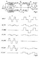
- Fig. 6 shows diagrams of signals occurring in the arrangement according to Fig. 5 for a higher and a lower flicker frequency (case A and B).
- the flicker component INPUT has the amplitudes zero, positive, zero, negative a.s.o. for one frame each.
- the flicker component remains on each amplitude level for two frames.
- the picture content is assumed to be zero (or constant), and only the variation of the brightness from frame to frame is shown in the diagram.
- the image signal should split into a spatial low-pass and high-pass component, and only the low-pass signal is processed by the arrangement of Fig. 5.
- the arrangement shown in Fig. 3 could be used advantageously for splitting the image signal into a high frequency and a low frequency (or low detail) component.
- the temporal high-pass signals HP_FIR and HP_MED are derived by subtracting the individual low-pass components LP_FIR and LP_MED from the input signal. The maximum of both results in the high-pass output HP_OUT of the arrangement.
- the high-pass output isolates the flicker components, which are to be subtracted from the input signal in order to perform the desired flicker reduction.
- Fig. 6 shows that flicker with a high frequency can be reduced better with a median filter, whereas the FIR filter performs better with a lower flicker component.
- the 3 tap median filter is able to cancel single frames (case A) with either positive or negative variations of the intensity, whereas the FIR filter just gives a reduction of 66%.
- the median filter stops working as soon as two subsequent frames have the same intensity of flicker (case B). But the FIR filter still produces a mean intensity LP_FIR, which is still 33% below the original value. So the FIR high-pass filter isolates more low frequency flicker HP_FIR than the median filter HP_MED.
- the inventive arrangement is always able to perform the best reduction by either the median or the FIR filter.
Landscapes
- Physics & Mathematics (AREA)
- General Physics & Mathematics (AREA)
- Engineering & Computer Science (AREA)
- Theoretical Computer Science (AREA)
- Picture Signal Circuits (AREA)
Priority Applications (1)
| Application Number | Priority Date | Filing Date | Title |
|---|---|---|---|
| EP20020007904 EP1258833B1 (de) | 2001-04-20 | 2002-04-08 | Anordnung zur Verarbeitung von Videosignalen |
Applications Claiming Priority (3)
| Application Number | Priority Date | Filing Date | Title |
|---|---|---|---|
| EP01109747 | 2001-04-20 | ||
| EP01109747A EP1251463A1 (de) | 2001-04-20 | 2001-04-20 | Anordnung zur Verarbeitung von Videosignalen |
| EP20020007904 EP1258833B1 (de) | 2001-04-20 | 2002-04-08 | Anordnung zur Verarbeitung von Videosignalen |
Publications (3)
| Publication Number | Publication Date |
|---|---|
| EP1258833A2 true EP1258833A2 (de) | 2002-11-20 |
| EP1258833A3 EP1258833A3 (de) | 2004-08-18 |
| EP1258833B1 EP1258833B1 (de) | 2008-09-17 |
Family
ID=26076555
Family Applications (1)
| Application Number | Title | Priority Date | Filing Date |
|---|---|---|---|
| EP20020007904 Expired - Fee Related EP1258833B1 (de) | 2001-04-20 | 2002-04-08 | Anordnung zur Verarbeitung von Videosignalen |
Country Status (1)
| Country | Link |
|---|---|
| EP (1) | EP1258833B1 (de) |
Cited By (1)
| Publication number | Priority date | Publication date | Assignee | Title |
|---|---|---|---|---|
| EP1489742A2 (de) * | 2003-06-18 | 2004-12-22 | Micronas GmbH | Verfahren und Vorrichtung zur Filterung eines Signals |
Citations (2)
| Publication number | Priority date | Publication date | Assignee | Title |
|---|---|---|---|---|
| US5412432A (en) * | 1992-11-30 | 1995-05-02 | Goldstar Co., Ltd. | Apparatus and method for enhancing transient edge of video signal |
| US5434627A (en) * | 1991-01-24 | 1995-07-18 | British Broadcasting Corporation | Codec for weston clean pal television system |
-
2002
- 2002-04-08 EP EP20020007904 patent/EP1258833B1/de not_active Expired - Fee Related
Patent Citations (2)
| Publication number | Priority date | Publication date | Assignee | Title |
|---|---|---|---|---|
| US5434627A (en) * | 1991-01-24 | 1995-07-18 | British Broadcasting Corporation | Codec for weston clean pal television system |
| US5412432A (en) * | 1992-11-30 | 1995-05-02 | Goldstar Co., Ltd. | Apparatus and method for enhancing transient edge of video signal |
Cited By (2)
| Publication number | Priority date | Publication date | Assignee | Title |
|---|---|---|---|---|
| EP1489742A2 (de) * | 2003-06-18 | 2004-12-22 | Micronas GmbH | Verfahren und Vorrichtung zur Filterung eines Signals |
| EP1489742A3 (de) * | 2003-06-18 | 2006-01-18 | Micronas GmbH | Verfahren und Vorrichtung zur Filterung eines Signals |
Also Published As
| Publication number | Publication date |
|---|---|
| EP1258833B1 (de) | 2008-09-17 |
| EP1258833A3 (de) | 2004-08-18 |
Similar Documents
| Publication | Publication Date | Title |
|---|---|---|
| EP2249556A2 (de) | Verfahren und Vorrichtung zur Bildverarbeitung | |
| US6614944B1 (en) | Image enhancement filter with adaptive threshold | |
| US4951144A (en) | Recursive video blur effect | |
| US7061546B2 (en) | Arrangement for processing video signals | |
| JP3879543B2 (ja) | 画像処理装置 | |
| EP0114961A2 (de) | Nichtlineares Filtern von graustufigen Bildern | |
| US20030007100A1 (en) | Electronic circuit and method for enhancing an image | |
| NL8002699A (nl) | Inrichting voor het verwerken van vertikale detail- signalen van een videobeeld. | |
| Mohapatra et al. | Histogram equalization and noise removal process for enhancement of image | |
| US5828366A (en) | Non-linear interline flicker reducer | |
| JP4768510B2 (ja) | 画質改善装置および画質改善方法 | |
| KR20020033095A (ko) | 원래 이미지 픽셀을 n 차원 필터링하는 n 차원 필터 및방법 | |
| EP1258833B1 (de) | Anordnung zur Verarbeitung von Videosignalen | |
| JPH02272894A (ja) | カラー映像信号エンコード方法 | |
| US6201582B1 (en) | Circuit for moiré suppression | |
| EP1766994A1 (de) | Vorverarbeitungseinrichtung und verfahren vor der codierung einer videobildsequenz | |
| US20030021475A1 (en) | Image resizing using short asymmetric FIR filters | |
| JPS63312791A (ja) | 映像デコード方法 | |
| JP2003032513A (ja) | 画像信号処理装置 | |
| JPH06319129A (ja) | 時空間画像フィルタ | |
| JPH09312788A (ja) | 雑音低減回路 | |
| US20040012334A1 (en) | Video signal processing | |
| JPH11346320A (ja) | 映像信号処理装置 | |
| EP0546469A1 (de) | Verfahren und Vorrichtung zur vertikalen Interpolation | |
| EP0683605B1 (de) | Verfahren und Vorrichtung zum verbessern der Übergänge von Videosignalkomponenten |
Legal Events
| Date | Code | Title | Description |
|---|---|---|---|
| PUAI | Public reference made under article 153(3) epc to a published international application that has entered the european phase |
Free format text: ORIGINAL CODE: 0009012 |
|
| AK | Designated contracting states |
Kind code of ref document: A2 Designated state(s): AT BE CH CY DE DK ES FI FR GB GR IE IT LI LU MC NL PT SE TR |
|
| AX | Request for extension of the european patent |
Free format text: AL;LT;LV;MK;RO;SI |
|
| PUAL | Search report despatched |
Free format text: ORIGINAL CODE: 0009013 |
|
| AK | Designated contracting states |
Kind code of ref document: A3 Designated state(s): AT BE CH CY DE DK ES FI FR GB GR IE IT LI LU MC NL PT SE TR |
|
| AX | Request for extension of the european patent |
Extension state: AL LT LV MK RO SI |
|
| 17P | Request for examination filed |
Effective date: 20050211 |
|
| AKX | Designation fees paid |
Designated state(s): DE FR GB |
|
| 17Q | First examination report despatched |
Effective date: 20070807 |
|
| GRAP | Despatch of communication of intention to grant a patent |
Free format text: ORIGINAL CODE: EPIDOSNIGR1 |
|
| GRAS | Grant fee paid |
Free format text: ORIGINAL CODE: EPIDOSNIGR3 |
|
| GRAA | (expected) grant |
Free format text: ORIGINAL CODE: 0009210 |
|
| AK | Designated contracting states |
Kind code of ref document: B1 Designated state(s): DE FR GB |
|
| REG | Reference to a national code |
Ref country code: GB Ref legal event code: FG4D |
|
| REG | Reference to a national code |
Ref country code: GB Ref legal event code: 746 Effective date: 20080908 |
|
| REF | Corresponds to: |
Ref document number: 60228913 Country of ref document: DE Date of ref document: 20081030 Kind code of ref document: P |
|
| PLBE | No opposition filed within time limit |
Free format text: ORIGINAL CODE: 0009261 |
|
| STAA | Information on the status of an ep patent application or granted ep patent |
Free format text: STATUS: NO OPPOSITION FILED WITHIN TIME LIMIT |
|
| 26N | No opposition filed |
Effective date: 20090618 |
|
| REG | Reference to a national code |
Ref country code: FR Ref legal event code: PLFP Year of fee payment: 15 |
|
| REG | Reference to a national code |
Ref country code: FR Ref legal event code: PLFP Year of fee payment: 16 |
|
| REG | Reference to a national code |
Ref country code: FR Ref legal event code: PLFP Year of fee payment: 17 |
|
| REG | Reference to a national code |
Ref country code: DE Ref legal event code: R082 Ref document number: 60228913 Country of ref document: DE Representative=s name: DEHNS, DE Ref country code: DE Ref legal event code: R081 Ref document number: 60228913 Country of ref document: DE Owner name: INTERDIGITAL CE PATENT HOLDINGS, FR Free format text: FORMER OWNER: BTS MEDIA SOLUTIONS GMBH, 64331 WEITERSTADT, DE Ref country code: DE Ref legal event code: R082 Ref document number: 60228913 Country of ref document: DE Representative=s name: DEHNS PATENT AND TRADEMARK ATTORNEYS, DE |
|
| REG | Reference to a national code |
Ref country code: GB Ref legal event code: 732E Free format text: REGISTERED BETWEEN 20200611 AND 20200617 |
|
| PGFP | Annual fee paid to national office [announced via postgrant information from national office to epo] |
Ref country code: DE Payment date: 20200430 Year of fee payment: 19 Ref country code: FR Payment date: 20200429 Year of fee payment: 19 |
|
| PGFP | Annual fee paid to national office [announced via postgrant information from national office to epo] |
Ref country code: GB Payment date: 20200429 Year of fee payment: 19 |
|
| REG | Reference to a national code |
Ref country code: DE Ref legal event code: R119 Ref document number: 60228913 Country of ref document: DE |
|
| GBPC | Gb: european patent ceased through non-payment of renewal fee |
Effective date: 20210408 |
|
| PG25 | Lapsed in a contracting state [announced via postgrant information from national office to epo] |
Ref country code: GB Free format text: LAPSE BECAUSE OF NON-PAYMENT OF DUE FEES Effective date: 20210408 Ref country code: FR Free format text: LAPSE BECAUSE OF NON-PAYMENT OF DUE FEES Effective date: 20210430 Ref country code: DE Free format text: LAPSE BECAUSE OF NON-PAYMENT OF DUE FEES Effective date: 20211103 |