EP1257443B1 - Sensoranordnung - Google Patents
Sensoranordnung Download PDFInfo
- Publication number
- EP1257443B1 EP1257443B1 EP01905719A EP01905719A EP1257443B1 EP 1257443 B1 EP1257443 B1 EP 1257443B1 EP 01905719 A EP01905719 A EP 01905719A EP 01905719 A EP01905719 A EP 01905719A EP 1257443 B1 EP1257443 B1 EP 1257443B1
- Authority
- EP
- European Patent Office
- Prior art keywords
- sensor arrangement
- carrier board
- arrangement according
- sensor
- sensor element
- Prior art date
- Legal status (The legal status is an assumption and is not a legal conclusion. Google has not performed a legal analysis and makes no representation as to the accuracy of the status listed.)
- Expired - Lifetime
Links
Images

Classifications
-
- B—PERFORMING OPERATIONS; TRANSPORTING
- B60—VEHICLES IN GENERAL
- B60S—SERVICING, CLEANING, REPAIRING, SUPPORTING, LIFTING, OR MANOEUVRING OF VEHICLES, NOT OTHERWISE PROVIDED FOR
- B60S1/00—Cleaning of vehicles
- B60S1/02—Cleaning windscreens, windows or optical devices
- B60S1/04—Wipers or the like, e.g. scrapers
- B60S1/06—Wipers or the like, e.g. scrapers characterised by the drive
- B60S1/08—Wipers or the like, e.g. scrapers characterised by the drive electrically driven
- B60S1/0818—Wipers or the like, e.g. scrapers characterised by the drive electrically driven including control systems responsive to external conditions, e.g. by detection of moisture, dirt or the like
- B60S1/0822—Wipers or the like, e.g. scrapers characterised by the drive electrically driven including control systems responsive to external conditions, e.g. by detection of moisture, dirt or the like characterized by the arrangement or type of detection means
- B60S1/0825—Capacitive rain sensor
-
- B—PERFORMING OPERATIONS; TRANSPORTING
- B32—LAYERED PRODUCTS
- B32B—LAYERED PRODUCTS, i.e. PRODUCTS BUILT-UP OF STRATA OF FLAT OR NON-FLAT, e.g. CELLULAR OR HONEYCOMB, FORM
- B32B17/00—Layered products essentially comprising sheet glass, or glass, slag, or like fibres
- B32B17/06—Layered products essentially comprising sheet glass, or glass, slag, or like fibres comprising glass as the main or only constituent of a layer, next to another layer of a specific material
- B32B17/10—Layered products essentially comprising sheet glass, or glass, slag, or like fibres comprising glass as the main or only constituent of a layer, next to another layer of a specific material of synthetic resin
- B32B17/10005—Layered products essentially comprising sheet glass, or glass, slag, or like fibres comprising glass as the main or only constituent of a layer, next to another layer of a specific material of synthetic resin laminated safety glass or glazing
- B32B17/10009—Layered products essentially comprising sheet glass, or glass, slag, or like fibres comprising glass as the main or only constituent of a layer, next to another layer of a specific material of synthetic resin laminated safety glass or glazing characterized by the number, the constitution or treatment of glass sheets
- B32B17/10018—Layered products essentially comprising sheet glass, or glass, slag, or like fibres comprising glass as the main or only constituent of a layer, next to another layer of a specific material of synthetic resin laminated safety glass or glazing characterized by the number, the constitution or treatment of glass sheets comprising only one glass sheet
-
- B—PERFORMING OPERATIONS; TRANSPORTING
- B32—LAYERED PRODUCTS
- B32B—LAYERED PRODUCTS, i.e. PRODUCTS BUILT-UP OF STRATA OF FLAT OR NON-FLAT, e.g. CELLULAR OR HONEYCOMB, FORM
- B32B17/00—Layered products essentially comprising sheet glass, or glass, slag, or like fibres
- B32B17/06—Layered products essentially comprising sheet glass, or glass, slag, or like fibres comprising glass as the main or only constituent of a layer, next to another layer of a specific material
- B32B17/10—Layered products essentially comprising sheet glass, or glass, slag, or like fibres comprising glass as the main or only constituent of a layer, next to another layer of a specific material of synthetic resin
- B32B17/10005—Layered products essentially comprising sheet glass, or glass, slag, or like fibres comprising glass as the main or only constituent of a layer, next to another layer of a specific material of synthetic resin laminated safety glass or glazing
- B32B17/1055—Layered products essentially comprising sheet glass, or glass, slag, or like fibres comprising glass as the main or only constituent of a layer, next to another layer of a specific material of synthetic resin laminated safety glass or glazing characterized by the resin layer, i.e. interlayer
-
- B—PERFORMING OPERATIONS; TRANSPORTING
- B60—VEHICLES IN GENERAL
- B60H—ARRANGEMENTS OF HEATING, COOLING, VENTILATING OR OTHER AIR-TREATING DEVICES SPECIALLY ADAPTED FOR PASSENGER OR GOODS SPACES OF VEHICLES
- B60H1/00—Heating, cooling or ventilating devices
- B60H1/00642—Control systems or circuits; Control members or indication devices for heating, cooling or ventilating devices
- B60H1/00735—Control systems or circuits characterised by their input, i.e. by the detection, measurement or calculation of particular conditions, e.g. signal treatment, dynamic models
- B60H1/00785—Control systems or circuits characterised by their input, i.e. by the detection, measurement or calculation of particular conditions, e.g. signal treatment, dynamic models by the detection of humidity or frost
-
- B—PERFORMING OPERATIONS; TRANSPORTING
- B60—VEHICLES IN GENERAL
- B60S—SERVICING, CLEANING, REPAIRING, SUPPORTING, LIFTING, OR MANOEUVRING OF VEHICLES, NOT OTHERWISE PROVIDED FOR
- B60S1/00—Cleaning of vehicles
- B60S1/02—Cleaning windscreens, windows or optical devices
- B60S1/04—Wipers or the like, e.g. scrapers
- B60S1/06—Wipers or the like, e.g. scrapers characterised by the drive
- B60S1/08—Wipers or the like, e.g. scrapers characterised by the drive electrically driven
- B60S1/0818—Wipers or the like, e.g. scrapers characterised by the drive electrically driven including control systems responsive to external conditions, e.g. by detection of moisture, dirt or the like
- B60S1/0822—Wipers or the like, e.g. scrapers characterised by the drive electrically driven including control systems responsive to external conditions, e.g. by detection of moisture, dirt or the like characterized by the arrangement or type of detection means
-
- B—PERFORMING OPERATIONS; TRANSPORTING
- B60—VEHICLES IN GENERAL
- B60S—SERVICING, CLEANING, REPAIRING, SUPPORTING, LIFTING, OR MANOEUVRING OF VEHICLES, NOT OTHERWISE PROVIDED FOR
- B60S1/00—Cleaning of vehicles
- B60S1/02—Cleaning windscreens, windows or optical devices
- B60S1/04—Wipers or the like, e.g. scrapers
- B60S1/06—Wipers or the like, e.g. scrapers characterised by the drive
- B60S1/08—Wipers or the like, e.g. scrapers characterised by the drive electrically driven
- B60S1/0818—Wipers or the like, e.g. scrapers characterised by the drive electrically driven including control systems responsive to external conditions, e.g. by detection of moisture, dirt or the like
- B60S1/0822—Wipers or the like, e.g. scrapers characterised by the drive electrically driven including control systems responsive to external conditions, e.g. by detection of moisture, dirt or the like characterized by the arrangement or type of detection means
- B60S1/0874—Wipers or the like, e.g. scrapers characterised by the drive electrically driven including control systems responsive to external conditions, e.g. by detection of moisture, dirt or the like characterized by the arrangement or type of detection means characterized by the position of the sensor on the windshield
- B60S1/0888—Wipers or the like, e.g. scrapers characterised by the drive electrically driven including control systems responsive to external conditions, e.g. by detection of moisture, dirt or the like characterized by the arrangement or type of detection means characterized by the position of the sensor on the windshield characterized by the attachment of the elements in a unit
-
- G—PHYSICS
- G01—MEASURING; TESTING
- G01K—MEASURING TEMPERATURE; MEASURING QUANTITY OF HEAT; THERMALLY-SENSITIVE ELEMENTS NOT OTHERWISE PROVIDED FOR
- G01K1/00—Details of thermometers not specially adapted for particular types of thermometer
- G01K1/16—Special arrangements for conducting heat from the object to the sensitive element
-
- B—PERFORMING OPERATIONS; TRANSPORTING
- B60—VEHICLES IN GENERAL
- B60S—SERVICING, CLEANING, REPAIRING, SUPPORTING, LIFTING, OR MANOEUVRING OF VEHICLES, NOT OTHERWISE PROVIDED FOR
- B60S1/00—Cleaning of vehicles
- B60S1/02—Cleaning windscreens, windows or optical devices
- B60S1/04—Wipers or the like, e.g. scrapers
- B60S1/06—Wipers or the like, e.g. scrapers characterised by the drive
- B60S1/08—Wipers or the like, e.g. scrapers characterised by the drive electrically driven
- B60S1/0818—Wipers or the like, e.g. scrapers characterised by the drive electrically driven including control systems responsive to external conditions, e.g. by detection of moisture, dirt or the like
- B60S1/0822—Wipers or the like, e.g. scrapers characterised by the drive electrically driven including control systems responsive to external conditions, e.g. by detection of moisture, dirt or the like characterized by the arrangement or type of detection means
- B60S1/0874—Wipers or the like, e.g. scrapers characterised by the drive electrically driven including control systems responsive to external conditions, e.g. by detection of moisture, dirt or the like characterized by the arrangement or type of detection means characterized by the position of the sensor on the windshield
- B60S1/0881—Wipers or the like, e.g. scrapers characterised by the drive electrically driven including control systems responsive to external conditions, e.g. by detection of moisture, dirt or the like characterized by the arrangement or type of detection means characterized by the position of the sensor on the windshield characterized by the attachment means on the windshield
Definitions
- the present invention relates to a sensor arrangement, in particular suitable for detecting fogging on the inside of a car window is.
- the object of the present invention is therefore to provide a simple structure Specify sensor arrangement that is suitable for fogging a support surface, especially a motor vehicle window, reliably to detect.
- the proposed measures ensure that with the help of a single sensor arrangement according to the invention, fogging of a support surface, e.g. the inside of a car window, reliably detected and thus can be prevented.
- a support surface e.g. the inside of a car window
- the output signals of the Sensor arrangement according to the invention of a corresponding climate control or a regulated air conditioning system. It is recorded via the invention Sensor arrangement now only the relative humidity the support surface. This ensures that the sensor element used precisely detects the actual relative humidity on the carrier surface, since the sensor element has almost the same temperature in measuring mode as the support surface has.
- About various measures ensures that there is only a slight temperature difference between the support surface and the sensor element is present.
- the sensor arrangement according to the invention thus enables a reliable Solution of the fitting problem discussed above, which is only a minor one requires sensory effort.
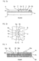
- Figure 1 a part of the inside of a motor vehicle window 1 is shown, which in this embodiment serves as a support surface and their fogging should be prevented.
- the sensor arrangement 10 On the side facing the passenger compartment of the Automotive window 1, the sensor arrangement 10 according to the invention is arranged; Figure 1 shows a first embodiment of such a sensor arrangement.
- the output signals of the sensor arrangement 10 are via a Connection cable 20 of a regulated automotive air conditioning system, not shown fed.
- the air conditioner prevents on the basis of the supplied moisture-dependent Sensor signals fogging up the inside of the vehicle window 1 and thus a possible visual impairment. This can be done via the vehicle air conditioning system the heating temperature in a known manner and / or the ventilation throughput can be changed in a defined manner, etc.
- the carrier board 11 is a commercially available printed circuit board Made of FR4 material and contains electrical conductor tracks for Contacting the components arranged on it.
- the sensor arrangement is connected via the connecting cable 20 10 with the downstream signal processing unit, for example one corresponding climate control of the vehicle air conditioning system.
- the connection cable 20 releasably connected to the carrier board 11, for example with the help of a suitable plug connection.
- the sensor element 12 is known as a capacitive one Thin-film moisture sensor, which is located between two electrodes a dielectric, e.g. a suitable polymer material, which its capacity changes depending on the humidity. Electrodes and dielectric are usually on a suitable carrier substrate, for example glass, arranged. On the output side, the sensor element 12 accordingly delivers in a known manner Way electrical signals that are a measure of relative Display humidity in the respective environment.
- a dielectric e.g. a suitable polymer material
- the sensor element 12 has a rectangular shape Recess 15 of the carrier board 11 arranged. About the Recess 15 in the carrier plate 11 is a certain air circulation in the Sensor area ensured. The longitudinal axis of the rectangular recess 15 is also perpendicular to the longitudinal axis of the sensor element 12 aligned. In this embodiment of the present invention, this is Sensor element 12 arranged on that side of the carrier board 11 that facing away from disc 1. For this reason, the sensor element 12, as well as the other components 13a - 13e on the carrier board 11, designed as an SMD component. The sensor element 12 thus has on that side in the area of the contact surface on the carrier board 11 electrically conductive contacts, which face the carrier board 11. Such is in particular a simple, rational manufacture of the invention Sensor arrangement 10 ensured because the carrier board 11 can be equipped automatically.
- the sensor element 12 is rectangular Has shape and a longer length in at least one dimension has as the recess 15, so that the sensor element 12 in two support areas rests on the carrier board 11.
- the further provided components 13a-13e on the carrier board 11 are used to process the output signals of the sensor element 12.
- Such signal processing can take the form of signal amplification, for example can also be carried out, the conversion into an easily transferable and further processable signal can be provided; other components can protect the sensor assembly 10 from electrical surges and disturbing electromagnetic interference, etc.
- the various electronic components 13a are advantageous - 13e provided on the carrier board 11 with a protective coating, the same protects against mechanical influences as well as against moisture and Contamination etc.
- a protective lacquer from Grace is suitable for this, which is sold under the type designation Eccocoat.
- FIGS. 2a and 2b each a partial sectional view of the sensor arrangement 10 from FIG. 1 in the area the recess 15 of the carrier board 11 shows. It is shown here again the motor vehicle window 1 with the sensor arrangement arranged above it 10th
- the carrier board 11 is in this embodiment via a heat-conducting layer 14 designed as an adhesive layer the car window 1, or the support surface, attached.
- the thermal layer 14 has various functions in the illustrated embodiment. The best possible heat conduction is of primary importance here Layer 14; furthermore, the heat-conducting layer 14 functions in this variant also as a fastening means for the carrier board arranged thereon 11 and the sensor element 12.
- the heat-conducting layer or adhesive layer formed as a double-sided adhesive adhesive film such as from available from 3M under the type designations 9882, 9885 or 9890 is. It is essential for the selection of a suitable adhesive layer that that it has the best possible heat conduction properties.
- the usual The thickness of the adhesive layer varies depending on the type used 0.05mm and 0.25mm.
- the moisture-sensitive sensor element 12 of which no further details can be seen in this illustration, is arranged above the recess 15. Suitable sensor elements 12 are sold, for example, by the applicant under the type designations HC102 or HC103 .
- the reference numerals 12a, 12b schematically indicate the electrically conductive contacts on the underside of the sensor element 12, via which the electrical contacting and connection thereof to the conductor tracks in the carrier board 11 takes place.
- the contacts 12a, 12b are located in the sensor element 12 in the support area in which it rests on the carrier board 11 outside the recess 15.
- the sensor element 12 used which in this embodiment as SMD component is formed, has a moisture-sensitive surface, as well how the contacts 12a, 12b are oriented toward the carrier board 11.
- the contacts 12a, 12b and the moisture sensitive surface are in this embodiment of a moisture-sensitive sensor element 12 accordingly arranged on the same side.
- the diameters of the bores 16a-16h are preferably identical to the diameters otherwise provided on the carrier board 11 Vias or holes selected, i.e. there are diameters chosen between 0.3mm and 0.8mm. It is also preferable - as in Figure 2b recognizable - several separate bores 16a - 16h with smaller ones Diameters instead of fewer holes with larger diameters in to mount the carrier board 11.
- the different bores 16a-16h point in this embodiment furthermore a coating which is as good a heat conductor as possible in the bore area on, for example a copper coating that has good heat conduction between the support surface 1 and the sensor element 12 via the Ensures bores 16a - 16h.
- the thermally conductive coating in the bore area is preferably as thick as possible, approximately thicker than 30 .mu.m. An additional tinning of such a copper coating again contributes to the improvement of the heat conduction properties.
- thermally conductive coatings on the bores 16a, 16b on the side of the carrier board 11 connected to one another in a heat-conducting manner be oriented in the direction of the sensor element 12. This can about a corresponding coating 17 of the carrier board 11 in one Area around the sensor element 12 and its connection contacts 12a, 12b can be provided, as can be seen in Figure 2b. This is how a thermally conductive connection between the different holes 16a - 16h.
- the holes 16a - 16h in the carrier board 11 and the use of Thermal layer 14 with good thermal conductivity properties provide in this Embodiment ensures that the sensor element 12 and the support surface 1 or the inside of the pane in measurement mode is largely identical Own temperature. This contributes to good thermal coupling Embodiment of the sensor arrangement according to the invention in the rest also the formation of the sensor element 12 as an SMD component, since such an intimate thermal contact with those upstream of the sensor element 12 Layers is ensured.
- the best possible thermal contact between the side of the disc 1, on which fogging is to be prevented and the sensor element 12, is thus essential for the sensor arrangement 10 according to the invention. At least however, it must be ensured that a certain - as low as possible - Temperature difference between carrier surface 1 and sensor element 12 in Measuring operation is not exceeded. In the present example the result is approximately a maximum temperature difference of approx. 0.5 ° C between that of the sensor element 12 facing side of the disc 1 and sensor element 12. Such a temperature gradient is still considered with respect to the measurement to be assessed uncritically.
- the sensor arrangement 110 On the inside of the vehicle window 100 or the corresponding support surface, whose fogging is to be prevented the sensor arrangement 110 is arranged.
- a heat-conducting layer 114 designed as an adhesive layer, and a carrier board 111 arranged above it, the one Has recess 115. In the area of the recess 115, this is sensitive to moisture Sensor element 112 arranged on the heat conducting layer 114.
- An electronic one is also indicated schematically in FIG Component 113a, which is used for further signal processing and on the Side of the carrier board 111 is arranged, which faces away from the car window 100 is oriented.
- the arrangement or Placement of the sensor element 112 in the sensor arrangement 110 is the sensor element 112 in the area of the recess 115 now directly on the formed as an adhesive layer Thermally conductive layer 114 arranged, the moisture sensitive surface of the sensor element 112 is oriented away from the motor vehicle window.
- an SMD thin-film moisture sensor is in turn directly on a double-sided adhesive film, the moisture sensitive Surface of the sensor element 112 towards the carrier board 111 is oriented.
- the electrical contacting of the sensor element 112 takes place from that Side of the sensor element 112, which faces away from the vehicle window or carrier surface 100 is oriented.
- Side of the sensor element 112 contacts 112a, 112b arranged through which the connection with the electrical conductor tracks in the carrier board 111.
- the sensor arrangement 110 consequently used the same moisture sensitive SMD sensor element become like in the previous example; only the orientation of the moisture sensitive Surface or the contacts 112a, 112b is now turned away chosen by the disc.
- electrical contacting is also possible in principle, the use of bond wires over which the contacts are possible of the sensor element with the conductor tracks in the carrier board electrically get connected.
Landscapes
- Engineering & Computer Science (AREA)
- Mechanical Engineering (AREA)
- Automation & Control Theory (AREA)
- Physics & Mathematics (AREA)
- Thermal Sciences (AREA)
- General Physics & Mathematics (AREA)
- Investigating Or Analyzing Materials By The Use Of Electric Means (AREA)
- Air-Conditioning For Vehicles (AREA)
- Investigating Or Analyzing Materials By The Use Of Ultrasonic Waves (AREA)
- Pressure Sensors (AREA)
- Measuring Fluid Pressure (AREA)
- Investigating Or Analyzing Materials By The Use Of Fluid Adsorption Or Reactions (AREA)
- Investigating Or Analyzing Materials Using Thermal Means (AREA)
Description
- Figur 1
- eine perspektivische Ansicht einer KFZ-Scheibe mit einer Ausführungsform der erfindungsgemäßen Sensoranordnung;
- Figur 2a und 2b
- je eine Teil-Schnittansicht der Sensoranordnung aus Figur 1;
- Figur 3
- eine Teil-Schnittansicht, jedoch keine Ausführungsform der erfindungsgemäßen Sensoranordnung.
Claims (14)
- Sensoranordnung zur Anordnung auf einer Trägerfläche, bestehend ausdadurch gekennzeichnet,einer auf der Trägerfläche (1) anordbaren Wärmeleitschicht (14), die eine gute Wärmeleitfähigkeit aufweist,einer Trägerplatine (11) auf der Wärmeleitschicht (14), wobei die Trägerplatine (11) mindestens eine Ausnehmung (15) sowie mehrere elektrische Leiterbahnen umfasst,einem feuchteempfindlichen Sensorelement (12), das im Bereich der Ausnehmung (15) der Trägerplatine (11) angeordnet ist und welches mit den Leiterbahnen auf der Trägerplatine (11) elektrisch leitend verbunden ist,dass das Sensorelement (12) auf derjenigen Seite der Trägerplatine (11) über der Ausnehmung angeordnet ist, welche dazu vorgesehen ist, abgewandt zur Trägerfläche (1) orientiert zu sein und die Trägerplatine (11) benachbart zur Ausnehmung (15) ein oder mehrere Bohrungen (16a - h) aufweist, wobei die Bohrungen (16a - h) mit einer wärmeleitfähigen Beschichtung versehen sind, so dass sichergestellt ist, dass zwischen dem Sensorelement (12) und der Trägerfläche (1) eine vorgegebene Temperaturdifferenz im Messbetrieb nicht überschritten wird unddass Befestigungsmittel zur Befestigung der Trägerplatine (11) und des Sensorelementes (12) auf der Trägerfläche (1) vorhanden sind.
- Sensoranordnung nach Anspruch 1, wobei als Trägerfläche (1) die dem Fahrgastraum zugewandte Innenseite einer KFZ-Scheibe fungiert.
- Sensoranordnung nach Anspruch 1, wobei auf der Trägerplatine (11) weitere Bauelemente (13a,..13e) zur Verarbeitung von Ausgangssignalen des Sensorelementes (12) angeordnet sind.
- Sensoranordnung nach Anspruch 3, wobei die Bauelemente (13a,..13e) mit einem Schutzüberzug versehen sind.
- Sensoranordnung nach Anspruch 1, wobei die Trägerplatine (11) eine lösbare Verbindung zu einem Anschlusskabel (20) aufweist.
- Sensoranordnung nach Anspruch 1, wobei die Trägerplatine (11) aus FR4-Material besteht.
- Sensoranordnung nach Anspruch 1, wobei die Wärmeleitschicht (14) als doppelseitig klebender Klebstofffilm ausgebildet ist, der gleichzeitig als Befestigungsmittel dient.
- Sensoranordnung nach Anspruch 1, wobei das Sensorelement (12) als kapazitiver Dünnschicht-Feuchtesensor ausgebildet ist, der ein zwischen mehreren Elektroden angeordnetes feuchteempfindliches Dielektrikum umfasst und eine feuchteempfindliche Fläche besitzt, die zur Trägerplatine (11) hin orientiert ist.
- Sensoranordnung nach Anspruch 1, wobei durch die Anordnung und Ausbildung der verschiedenen Elemente der Sensoranordnung (10) sichergestellt ist, dass zwischen dem Sensorelement (12) und der Trägerfläche (1) eine Temperaturdifferenz von 0.5°C im Messbetrieb nicht überschritten wird.
- Sensoranordnung nach Anspruch 1, wobei das Sensorelement (12) als SMD-Bauteil ausgebildet ist und auf derjenigen Seite elektrisch leitfähige Kontakte (12a, 12b) zur Verbindung mit den Leiterbahnen der Trägerplatine (11) aufweist, die der Trägerplatine (11) zugewandt ist.
- Sensoranordnung nach Anspruch 10, wobei das Sensorelement (12) zumindest in einer Dimension größer als die Ausnehmung (15) ausgebildet ist und in den Auflagebereichen außerhalb der Ausnehmung (15) die elektrisch leitfähigen Kontakte (12a, 12b) angeordnet sind.
- Sensoranordnung nach Anspruch 1, wobei die wärmeleitfähige Beschichtung aus Kupfer besteht.
- Sensoranordnung nach Anspruch 1, wobei die Beschichtung (17) auch in einem bestimmten Flächenbereich auf mindestens einer Seite der Trägerplatine (11) angeordnet ist und zwischen den verschiedenen Bohrungen (16a -16h) eine thermisch leitende Verbindung herstellt.
- Sensoranordnung nach Anspruch 1, wobei die Befestigungsmittel als mechanische Befestigungsmittel ausgebildet sind.
Priority Applications (1)
| Application Number | Priority Date | Filing Date | Title |
|---|---|---|---|
| EP03022704A EP1380481B1 (de) | 2000-02-11 | 2001-02-01 | Sensoranordnung |
Applications Claiming Priority (3)
| Application Number | Priority Date | Filing Date | Title |
|---|---|---|---|
| DE10006219 | 2000-02-11 | ||
| DE10006219 | 2000-02-11 | ||
| PCT/EP2001/001052 WO2001058731A1 (de) | 2000-02-11 | 2001-02-01 | Sensoranordnung |
Related Child Applications (1)
| Application Number | Title | Priority Date | Filing Date |
|---|---|---|---|
| EP03022704A Division EP1380481B1 (de) | 2000-02-11 | 2001-02-01 | Sensoranordnung |
Publications (2)
| Publication Number | Publication Date |
|---|---|
| EP1257443A1 EP1257443A1 (de) | 2002-11-20 |
| EP1257443B1 true EP1257443B1 (de) | 2004-01-07 |
Family
ID=7630665
Family Applications (2)
| Application Number | Title | Priority Date | Filing Date |
|---|---|---|---|
| EP03022704A Expired - Lifetime EP1380481B1 (de) | 2000-02-11 | 2001-02-01 | Sensoranordnung |
| EP01905719A Expired - Lifetime EP1257443B1 (de) | 2000-02-11 | 2001-02-01 | Sensoranordnung |
Family Applications Before (1)
| Application Number | Title | Priority Date | Filing Date |
|---|---|---|---|
| EP03022704A Expired - Lifetime EP1380481B1 (de) | 2000-02-11 | 2001-02-01 | Sensoranordnung |
Country Status (6)
| Country | Link |
|---|---|
| US (1) | US7028531B2 (de) |
| EP (2) | EP1380481B1 (de) |
| JP (1) | JP2003522334A (de) |
| AT (2) | ATE273816T1 (de) |
| DE (3) | DE50103364D1 (de) |
| WO (1) | WO2001058731A1 (de) |
Families Citing this family (31)
| Publication number | Priority date | Publication date | Assignee | Title |
|---|---|---|---|---|
| DE10051558C2 (de) * | 2000-10-18 | 2003-04-17 | Sitronic Elektrotech Ausruest | Sensoreinheit mit einem Luftfeuchte-Sensor und mit einem Lufttemperatur-Sensor |
| DE10152999C2 (de) * | 2001-10-26 | 2003-12-24 | Preh Elektro Feinmechanik | Sensor und Sensoreinheit zur Detektion einer Beschlagneigung |
| DE10243562B4 (de) * | 2002-09-19 | 2006-04-06 | J. Eberspächer GmbH & Co. KG | Temperiersystem für ein Fahrzeug |
| AU2004225188B2 (en) * | 2003-03-31 | 2010-04-15 | The General Hospital Corporation | Speckle reduction in optical coherence tomography by path length encoded angular compounding |
| DE10316933A1 (de) | 2003-04-12 | 2004-10-21 | E+E Elektronik Gmbh | Sensorsystem und Verfahren zu dessen Herstellung |
| DE10325971A1 (de) | 2003-06-07 | 2004-12-23 | E + E Elektronik Ges.M.B.H. | Basismodul für mehrere Sensoreinheiten |
| DE102004007341A1 (de) | 2004-02-16 | 2005-09-08 | Sitronic Gesellschaft für elektrotechnische Ausrüstung mbH. & Co. KG | Sensoreinrichtung zur Bestimmung einer Innenraumfeuchte und einer Feuchtigkeitsbeschlagsneigung und Befestigungsvorrichtung der Sensoreinrichtung |
| DE102004023156A1 (de) * | 2004-05-07 | 2005-12-15 | Siemens Ag | Sensor zur Bestimmung von Messgrößen, die zur Steuerung einer Klimaanlage und anderer ein Raumklima beeinflussenden Vorrichtungen geeignet sind |
| DE102004025010B3 (de) * | 2004-05-21 | 2006-02-16 | Behr-Hella Thermocontrol Gmbh | Vorrichtung zur Ermittlung von Beschlag auf einer Fläche eines Fahrzeuges |
| JP2006010547A (ja) * | 2004-06-28 | 2006-01-12 | Denso Corp | 湿度センサモジュールおよび湿度センサの実装構造 |
| DE102005003046A1 (de) | 2005-01-22 | 2006-07-27 | E + E Elektronik Ges.M.B.H. | Sensoranordnung |
| KR101170575B1 (ko) * | 2005-05-17 | 2012-08-01 | 한라공조주식회사 | 자동차의 디포깅 장치 및 그 제어방법 |
| DE102006032372A1 (de) * | 2005-07-19 | 2007-02-15 | Preh Gmbh | Kapazitiver Regensensor |
| ATE459496T1 (de) * | 2005-07-21 | 2010-03-15 | Preh Gmbh | Beschlagsensor |
| DE102005038466B4 (de) * | 2005-08-13 | 2007-12-13 | Sitronic Gesellschaft für elektrotechnische Ausrüstung mbH. & Co. KG | Sensoranordnung zur Temperaturmessung |
| US7373819B2 (en) * | 2005-09-30 | 2008-05-20 | Honeywell International Inc. | Stress sensitive humidity sensor based on a MEMS structure |
| DE102005062968B3 (de) * | 2005-12-28 | 2007-06-21 | Siemens Ag | Sensorelement für einen Kondensatsensor, Kondensatsensor, Klimaanlage und Halterung |
| DE102006004244B3 (de) * | 2006-01-30 | 2007-07-26 | Siemens Ag | Anordnung und Verfahren zur Überwachung der Betauung einer Fensterfläche |
| EP1700724B1 (de) | 2006-07-19 | 2009-09-02 | Sensirion Holding AG | Feuchtigkeitsfühler zur Ermittlung von Beschlag auf einem Fenster |
| DE102007047888A1 (de) | 2007-11-28 | 2009-08-13 | Sitronic Gesellschaft für elektrotechnische Ausrüstung mbH. & Co. KG | Sensoranordnung |
| DE102008014938B9 (de) | 2008-02-29 | 2015-10-29 | Stahlwerk Ergste Westig Gmbh | Verfahren zum Herstellen von Federschienen für Scheibenwischer |
| US8791532B2 (en) | 2009-11-18 | 2014-07-29 | Sensirion Ag | Sensor mounted in flip-chip technology on a substrate |
| US8736002B2 (en) | 2009-11-18 | 2014-05-27 | Sensirion Ag | Sensor mounted in flip-chip technology at a substrate edge |
| JP6641701B2 (ja) * | 2014-03-14 | 2020-02-05 | 株式会社リコー | 雰囲気センサとその製造方法、及び印刷物の製造方法 |
| DE102016007297A1 (de) * | 2016-06-16 | 2017-12-21 | Michael Salewski | Vorrichtung zur Erfassung von Meßwertänderungen an einem Einsatzort, aufweisend mindestens ein elektrisch leitendes Element |
| DE102016122428A1 (de) * | 2016-11-22 | 2018-05-24 | Valeo Schalter Und Sensoren Gmbh | Regensensoranordnung mit Temperatursensor |
| US11137314B2 (en) * | 2018-03-07 | 2021-10-05 | Steering Solutions Ip Holding Corporation | Water intrusion detection |
| US11738716B2 (en) * | 2019-03-20 | 2023-08-29 | Littelfuse, Inc. | Automobile rain and temperature sensor module with transparent compound contacts the transparent cover plate of a housing and particularly encases the light emitter and light receiver disposed within |
| CN112578003A (zh) * | 2019-09-30 | 2021-03-30 | 浙江三花智能控制股份有限公司 | 传感元件 |
| CN112109847B (zh) * | 2020-08-27 | 2021-11-16 | 上海外高桥造船有限公司 | 一种客船驾驶室窗除雾末端装置 |
| CN115997478B (zh) * | 2020-08-28 | 2026-03-17 | 旭硝子欧洲玻璃公司 | 嵌装玻璃热传感器 |
Citations (1)
| Publication number | Priority date | Publication date | Assignee | Title |
|---|---|---|---|---|
| US5189902A (en) * | 1990-01-08 | 1993-03-02 | E. G. & G. | Humidity sensor, and a measurement installation including a plurality of such sensors |
Family Cites Families (16)
| Publication number | Priority date | Publication date | Assignee | Title |
|---|---|---|---|---|
| FR2218710B1 (de) | 1973-02-16 | 1976-04-30 | Saint Gobain | |
| FR2268425B1 (de) | 1974-04-19 | 1977-10-14 | Saint Gobain | |
| JPS5660715A (en) | 1979-10-20 | 1981-05-25 | Diesel Kiki Co Ltd | Defrosting control method and apparatus for air conditioner of automobile |
| FR2601913B1 (fr) * | 1986-07-24 | 1988-12-02 | Manzoni Bouchot Sa | Dispositif de chauffage pour sonde hygrometrique de commande d'essuie-glace pour vehicules. |
| DE3721659A1 (de) | 1987-06-26 | 1989-01-05 | Siemens Ag | Anordnung zum belueften des innenraumes eines kraftfahrzeuges |
| US4942364A (en) * | 1988-02-19 | 1990-07-17 | Asahi Kasei Kogyo Kabushiki Kaisha | Moisture and dew-detection sensor |
| JP2717424B2 (ja) | 1988-10-29 | 1998-02-18 | 富士重工業株式会社 | 車両用ウィンドシールドの着霜防止装置 |
| JPH02216347A (ja) | 1989-02-15 | 1990-08-29 | Fuji Heavy Ind Ltd | 車両用着霜防止装置 |
| WO1994018701A1 (en) * | 1993-02-05 | 1994-08-18 | W.L. Gore & Associates, Inc. | Stress-resistant semiconductor chip-circuit board interconnect |
| FR2729894A1 (fr) * | 1995-01-26 | 1996-08-02 | Saint Gobain Vitrage | Vitrage feuillete equipe d'un detecteur |
| US5798909A (en) * | 1995-02-15 | 1998-08-25 | International Business Machines Corporation | Single-tiered organic chip carriers for wire bond-type chips |
| AT1469U1 (de) * | 1996-04-10 | 1997-05-26 | E & E Elektronik Gmbh | Verfahren zum ermitteln der absoluten luftfeuchtigkeit |
| DE19616715A1 (de) | 1996-04-26 | 1997-11-06 | Hoersch Guenter | Feuchtigkeitssensor |
| FR2751593B1 (fr) * | 1996-07-24 | 1998-09-04 | Saint Gobain Vitrage | Vitrage feuillete equipe d'un detecteur |
| US5708566A (en) * | 1996-10-31 | 1998-01-13 | Motorola, Inc. | Solder bonded electronic module |
| US6466113B1 (en) * | 1999-01-22 | 2002-10-15 | Spectrian Corporation | Multi-layer RF printed circuit architecture with low-inductance interconnection and low thermal resistance for wide-lead power devices |
-
2001
- 2001-02-01 EP EP03022704A patent/EP1380481B1/de not_active Expired - Lifetime
- 2001-02-01 WO PCT/EP2001/001052 patent/WO2001058731A1/de not_active Ceased
- 2001-02-01 DE DE50103364T patent/DE50103364D1/de not_active Expired - Lifetime
- 2001-02-01 JP JP2001558299A patent/JP2003522334A/ja not_active Withdrawn
- 2001-02-01 EP EP01905719A patent/EP1257443B1/de not_active Expired - Lifetime
- 2001-02-01 US US10/203,600 patent/US7028531B2/en not_active Expired - Fee Related
- 2001-02-01 DE DE50101290T patent/DE50101290D1/de not_active Expired - Lifetime
- 2001-02-01 DE DE10104942A patent/DE10104942A1/de not_active Withdrawn
- 2001-02-01 AT AT03022704T patent/ATE273816T1/de active
- 2001-02-01 AT AT01905719T patent/ATE257440T1/de active
Patent Citations (1)
| Publication number | Priority date | Publication date | Assignee | Title |
|---|---|---|---|---|
| US5189902A (en) * | 1990-01-08 | 1993-03-02 | E. G. & G. | Humidity sensor, and a measurement installation including a plurality of such sensors |
Also Published As
| Publication number | Publication date |
|---|---|
| ATE257440T1 (de) | 2004-01-15 |
| US7028531B2 (en) | 2006-04-18 |
| EP1380481A2 (de) | 2004-01-14 |
| DE50103364D1 (de) | 2004-09-23 |
| US20030140681A1 (en) | 2003-07-31 |
| DE10104942A1 (de) | 2001-08-16 |
| WO2001058731A1 (de) | 2001-08-16 |
| EP1257443A1 (de) | 2002-11-20 |
| DE50101290D1 (de) | 2004-02-12 |
| EP1380481A3 (de) | 2004-01-21 |
| JP2003522334A (ja) | 2003-07-22 |
| ATE273816T1 (de) | 2004-09-15 |
| EP1380481B1 (de) | 2004-08-18 |
Similar Documents
| Publication | Publication Date | Title |
|---|---|---|
| EP1380481B1 (de) | Sensoranordnung | |
| EP1306242B1 (de) | Sensor zur Detektion einer Beschlagsneigung sowie Sensormodul | |
| EP1875180B1 (de) | Sensoranordnung zur temperaturmessung | |
| DE102007009672B4 (de) | Klimabedienteil mit einer Sensoranordnung | |
| DE102010030769B4 (de) | Temperaturfühler zur Messung einer Fahrzeuginnentemperatur | |
| EP1328796B1 (de) | Sensoreinheit mit einem luftfeuchte-sensor und mit einem lufttemperatur-sensor | |
| DE102009026439A1 (de) | Sensorelement und Verfahren zur Herstellung eines solchen | |
| EP1636055B1 (de) | Basismodul für mehrere sensoreinheiten | |
| EP1564044B1 (de) | Befestigungsvorrichtung mit einer Sensoreinrichtung zur Bestimmung einer Innenraumfeuchte und einer Feuchtigkeitsbeschlagsneigung | |
| EP1915599B1 (de) | Sensoranordnung zur temperaturmessung | |
| EP1683665B1 (de) | Sensoranordnung | |
| EP1951535B1 (de) | Beschlagsensor | |
| DE102020212435A1 (de) | Platinensystem mit auflaminierten Lagen | |
| WO2006072492A1 (de) | Gassensormodul | |
| EP2098845B1 (de) | Keramischer Drucksensor | |
| DE102016200267A1 (de) | Mikromechanische Vorrichtung und Verfahren zum Detektieren eines Gases | |
| DE10343793A1 (de) | Heissfilmluftmassensensor mit Kontaktierung mittels anisotropem Leitkleber | |
| EP1859259B1 (de) | Vorrichtung, insbesondere zur messung der feuchte, mit korrosionsgeschützten anschlüssen | |
| DE102005006772A1 (de) | Sensorelement mit Verbindungsleitung | |
| DE29814196U1 (de) | Differenzdrucksensor | |
| DE20023161U1 (de) | Sensoreinheit mit einem Luftfeuchte-Sensor und mit einem Lufttemperatur-Sensor |
Legal Events
| Date | Code | Title | Description |
|---|---|---|---|
| PUAI | Public reference made under article 153(3) epc to a published international application that has entered the european phase |
Free format text: ORIGINAL CODE: 0009012 |
|
| 17P | Request for examination filed |
Effective date: 20020911 |
|
| AK | Designated contracting states |
Kind code of ref document: A1 Designated state(s): AT BE CH CY DE DK ES FI FR GB GR IE IT LI LU MC NL PT SE TR |
|
| GRAP | Despatch of communication of intention to grant a patent |
Free format text: ORIGINAL CODE: EPIDOSNIGR1 |
|
| GRAS | Grant fee paid |
Free format text: ORIGINAL CODE: EPIDOSNIGR3 |
|
| GRAA | (expected) grant |
Free format text: ORIGINAL CODE: 0009210 |
|
| AK | Designated contracting states |
Kind code of ref document: B1 Designated state(s): AT DE FR GB IT |
|
| REG | Reference to a national code |
Ref country code: GB Ref legal event code: FG4D Free format text: NOT ENGLISH |
|
| REG | Reference to a national code |
Ref country code: IE Ref legal event code: FG4D Free format text: GERMAN |
|
| REF | Corresponds to: |
Ref document number: 50101290 Country of ref document: DE Date of ref document: 20040212 Kind code of ref document: P |
|
| GBT | Gb: translation of ep patent filed (gb section 77(6)(a)/1977) |
Effective date: 20040225 |
|
| REG | Reference to a national code |
Ref country code: IE Ref legal event code: FD4D |
|
| ET | Fr: translation filed | ||
| PLBE | No opposition filed within time limit |
Free format text: ORIGINAL CODE: 0009261 |
|
| STAA | Information on the status of an ep patent application or granted ep patent |
Free format text: STATUS: NO OPPOSITION FILED WITHIN TIME LIMIT |
|
| 26N | No opposition filed |
Effective date: 20041008 |
|
| PGFP | Annual fee paid to national office [announced via postgrant information from national office to epo] |
Ref country code: FR Payment date: 20120227 Year of fee payment: 12 |
|
| PGFP | Annual fee paid to national office [announced via postgrant information from national office to epo] |
Ref country code: DE Payment date: 20120221 Year of fee payment: 12 |
|
| PGFP | Annual fee paid to national office [announced via postgrant information from national office to epo] |
Ref country code: GB Payment date: 20120221 Year of fee payment: 12 Ref country code: IT Payment date: 20120223 Year of fee payment: 12 |
|
| PGFP | Annual fee paid to national office [announced via postgrant information from national office to epo] |
Ref country code: AT Payment date: 20120213 Year of fee payment: 12 |
|
| REG | Reference to a national code |
Ref country code: AT Ref legal event code: MM01 Ref document number: 257440 Country of ref document: AT Kind code of ref document: T Effective date: 20130228 |
|
| GBPC | Gb: european patent ceased through non-payment of renewal fee |
Effective date: 20130201 |
|
| PG25 | Lapsed in a contracting state [announced via postgrant information from national office to epo] |
Ref country code: AT Free format text: LAPSE BECAUSE OF NON-PAYMENT OF DUE FEES Effective date: 20130228 |
|
| REG | Reference to a national code |
Ref country code: FR Ref legal event code: ST Effective date: 20131031 |
|
| REG | Reference to a national code |
Ref country code: DE Ref legal event code: R119 Ref document number: 50101290 Country of ref document: DE Effective date: 20130903 |
|
| PG25 | Lapsed in a contracting state [announced via postgrant information from national office to epo] |
Ref country code: IT Free format text: LAPSE BECAUSE OF NON-PAYMENT OF DUE FEES Effective date: 20130201 |
|
| PG25 | Lapsed in a contracting state [announced via postgrant information from national office to epo] |
Ref country code: GB Free format text: LAPSE BECAUSE OF NON-PAYMENT OF DUE FEES Effective date: 20130201 Ref country code: DE Free format text: LAPSE BECAUSE OF NON-PAYMENT OF DUE FEES Effective date: 20130903 Ref country code: FR Free format text: LAPSE BECAUSE OF NON-PAYMENT OF DUE FEES Effective date: 20130228 |