EP1257342B1 - Filter cartridge and combination of blower wheel and filter cartridge - Google Patents
Filter cartridge and combination of blower wheel and filter cartridge Download PDFInfo
- Publication number
- EP1257342B1 EP1257342B1 EP00947174A EP00947174A EP1257342B1 EP 1257342 B1 EP1257342 B1 EP 1257342B1 EP 00947174 A EP00947174 A EP 00947174A EP 00947174 A EP00947174 A EP 00947174A EP 1257342 B1 EP1257342 B1 EP 1257342B1
- Authority
- EP
- European Patent Office
- Prior art keywords
- filter cartridge
- filter
- compartments
- mesh
- blower wheel
- Prior art date
- Legal status (The legal status is an assumption and is not a legal conclusion. Google has not performed a legal analysis and makes no representation as to the accuracy of the status listed.)
- Expired - Lifetime
Links
- OKTJSMMVPCPJKN-UHFFFAOYSA-N Carbon Chemical compound [C] OKTJSMMVPCPJKN-UHFFFAOYSA-N 0.000 claims description 32
- 229910052799 carbon Inorganic materials 0.000 claims description 28
- 238000001914 filtration Methods 0.000 claims description 19
- 239000000463 material Substances 0.000 claims description 16
- 239000002594 sorbent Substances 0.000 claims description 6
- YXFVVABEGXRONW-UHFFFAOYSA-N Toluene Chemical compound CC1=CC=CC=C1 YXFVVABEGXRONW-UHFFFAOYSA-N 0.000 description 18
- 238000012360 testing method Methods 0.000 description 13
- 239000007789 gas Substances 0.000 description 9
- 239000002245 particle Substances 0.000 description 8
- 238000013461 design Methods 0.000 description 6
- 238000000034 method Methods 0.000 description 6
- 230000009467 reduction Effects 0.000 description 6
- 239000007787 solid Substances 0.000 description 5
- 230000000694 effects Effects 0.000 description 4
- 239000000835 fiber Substances 0.000 description 4
- 229910052751 metal Inorganic materials 0.000 description 4
- 239000002184 metal Substances 0.000 description 4
- 230000000717 retained effect Effects 0.000 description 4
- 230000007423 decrease Effects 0.000 description 3
- 230000007613 environmental effect Effects 0.000 description 3
- 230000035699 permeability Effects 0.000 description 3
- 229920001944 Plastisol Polymers 0.000 description 2
- 239000000853 adhesive Substances 0.000 description 2
- 230000001070 adhesive effect Effects 0.000 description 2
- 239000000443 aerosol Substances 0.000 description 2
- 230000015572 biosynthetic process Effects 0.000 description 2
- 239000000356 contaminant Substances 0.000 description 2
- 230000000873 masking effect Effects 0.000 description 2
- 239000004999 plastisol Substances 0.000 description 2
- 238000009420 retrofitting Methods 0.000 description 2
- 230000035945 sensitivity Effects 0.000 description 2
- 238000012546 transfer Methods 0.000 description 2
- 230000008016 vaporization Effects 0.000 description 2
- UGFAIRIUMAVXCW-UHFFFAOYSA-N Carbon monoxide Chemical compound [O+]#[C-] UGFAIRIUMAVXCW-UHFFFAOYSA-N 0.000 description 1
- 229920001410 Microfiber Polymers 0.000 description 1
- CBENFWSGALASAD-UHFFFAOYSA-N Ozone Chemical compound [O-][O+]=O CBENFWSGALASAD-UHFFFAOYSA-N 0.000 description 1
- 241000555745 Sciuridae Species 0.000 description 1
- 230000009471 action Effects 0.000 description 1
- 238000013459 approach Methods 0.000 description 1
- 230000008901 benefit Effects 0.000 description 1
- 230000000903 blocking effect Effects 0.000 description 1
- 229910002091 carbon monoxide Inorganic materials 0.000 description 1
- 239000003054 catalyst Substances 0.000 description 1
- 239000002801 charged material Substances 0.000 description 1
- 238000001816 cooling Methods 0.000 description 1
- 238000012888 cubic function Methods 0.000 description 1
- 238000000151 deposition Methods 0.000 description 1
- 239000013536 elastomeric material Substances 0.000 description 1
- 239000004744 fabric Substances 0.000 description 1
- 239000006260 foam Substances 0.000 description 1
- 239000006261 foam material Substances 0.000 description 1
- 239000008187 granular material Substances 0.000 description 1
- 238000010438 heat treatment Methods 0.000 description 1
- 230000006872 improvement Effects 0.000 description 1
- 230000014759 maintenance of location Effects 0.000 description 1
- 238000004519 manufacturing process Methods 0.000 description 1
- 230000007246 mechanism Effects 0.000 description 1
- 239000000155 melt Substances 0.000 description 1
- 239000003658 microfiber Substances 0.000 description 1
- 238000005065 mining Methods 0.000 description 1
- 235000019645 odor Nutrition 0.000 description 1
- 238000005457 optimization Methods 0.000 description 1
- 230000035515 penetration Effects 0.000 description 1
- 239000011148 porous material Substances 0.000 description 1
- 230000008569 process Effects 0.000 description 1
- 230000000750 progressive effect Effects 0.000 description 1
- 230000003134 recirculating effect Effects 0.000 description 1
- 229920006395 saturated elastomer Polymers 0.000 description 1
- 238000007493 shaping process Methods 0.000 description 1
- 230000035943 smell Effects 0.000 description 1
- 238000009987 spinning Methods 0.000 description 1
- 230000003068 static effect Effects 0.000 description 1
- 229920001169 thermoplastic Polymers 0.000 description 1
- 229920001187 thermosetting polymer Polymers 0.000 description 1
- 239000004416 thermosoftening plastic Substances 0.000 description 1
- 238000009834 vaporization Methods 0.000 description 1
- 238000009423 ventilation Methods 0.000 description 1
- 238000003466 welding Methods 0.000 description 1
Images




Classifications
-
- B—PERFORMING OPERATIONS; TRANSPORTING
- B01—PHYSICAL OR CHEMICAL PROCESSES OR APPARATUS IN GENERAL
- B01D—SEPARATION
- B01D46/00—Filters or filtering processes specially modified for separating dispersed particles from gases or vapours
- B01D46/24—Particle separators, e.g. dust precipitators, using rigid hollow filter bodies
- B01D46/26—Particle separators, e.g. dust precipitators, using rigid hollow filter bodies rotatable
-
- B—PERFORMING OPERATIONS; TRANSPORTING
- B01—PHYSICAL OR CHEMICAL PROCESSES OR APPARATUS IN GENERAL
- B01D—SEPARATION
- B01D46/00—Filters or filtering processes specially modified for separating dispersed particles from gases or vapours
- B01D46/24—Particle separators, e.g. dust precipitators, using rigid hollow filter bodies
- B01D46/2403—Particle separators, e.g. dust precipitators, using rigid hollow filter bodies characterised by the physical shape or structure of the filtering element
- B01D46/2411—Filter cartridges
- B01D46/2414—End caps including additional functions or special forms
-
- B—PERFORMING OPERATIONS; TRANSPORTING
- B01—PHYSICAL OR CHEMICAL PROCESSES OR APPARATUS IN GENERAL
- B01D—SEPARATION
- B01D46/00—Filters or filtering processes specially modified for separating dispersed particles from gases or vapours
- B01D46/0039—Filters or filtering processes specially modified for separating dispersed particles from gases or vapours with flow guiding by feed or discharge devices
- B01D46/0041—Filters or filtering processes specially modified for separating dispersed particles from gases or vapours with flow guiding by feed or discharge devices for feeding
- B01D46/0045—Filters or filtering processes specially modified for separating dispersed particles from gases or vapours with flow guiding by feed or discharge devices for feeding by using vanes
-
- B—PERFORMING OPERATIONS; TRANSPORTING
- B01—PHYSICAL OR CHEMICAL PROCESSES OR APPARATUS IN GENERAL
- B01D—SEPARATION
- B01D46/00—Filters or filtering processes specially modified for separating dispersed particles from gases or vapours
- B01D46/0052—Filters or filtering processes specially modified for separating dispersed particles from gases or vapours with filtering elements moving during filtering operation
- B01D46/0056—Filters or filtering processes specially modified for separating dispersed particles from gases or vapours with filtering elements moving during filtering operation with rotational movement
-
- B—PERFORMING OPERATIONS; TRANSPORTING
- B60—VEHICLES IN GENERAL
- B60H—ARRANGEMENTS OF HEATING, COOLING, VENTILATING OR OTHER AIR-TREATING DEVICES SPECIALLY ADAPTED FOR PASSENGER OR GOODS SPACES OF VEHICLES
- B60H3/00—Other air-treating devices
- B60H3/06—Filtering
- B60H3/0658—Filter elements specially adapted for their arrangement in vehicles
-
- F—MECHANICAL ENGINEERING; LIGHTING; HEATING; WEAPONS; BLASTING
- F04—POSITIVE - DISPLACEMENT MACHINES FOR LIQUIDS; PUMPS FOR LIQUIDS OR ELASTIC FLUIDS
- F04D—NON-POSITIVE-DISPLACEMENT PUMPS
- F04D29/00—Details, component parts, or accessories
- F04D29/26—Rotors specially for elastic fluids
- F04D29/28—Rotors specially for elastic fluids for centrifugal or helico-centrifugal pumps for radial-flow or helico-centrifugal pumps
- F04D29/281—Rotors specially for elastic fluids for centrifugal or helico-centrifugal pumps for radial-flow or helico-centrifugal pumps for fans or blowers
- F04D29/282—Rotors specially for elastic fluids for centrifugal or helico-centrifugal pumps for radial-flow or helico-centrifugal pumps for fans or blowers the leading edge of each vane being substantially parallel to the rotation axis
-
- F—MECHANICAL ENGINEERING; LIGHTING; HEATING; WEAPONS; BLASTING
- F04—POSITIVE - DISPLACEMENT MACHINES FOR LIQUIDS; PUMPS FOR LIQUIDS OR ELASTIC FLUIDS
- F04D—NON-POSITIVE-DISPLACEMENT PUMPS
- F04D29/00—Details, component parts, or accessories
- F04D29/70—Suction grids; Strainers; Dust separation; Cleaning
- F04D29/701—Suction grids; Strainers; Dust separation; Cleaning especially adapted for elastic fluid pumps
- F04D29/703—Suction grids; Strainers; Dust separation; Cleaning especially adapted for elastic fluid pumps specially for fans, e.g. fan guards
-
- B—PERFORMING OPERATIONS; TRANSPORTING
- B01—PHYSICAL OR CHEMICAL PROCESSES OR APPARATUS IN GENERAL
- B01D—SEPARATION
- B01D2275/00—Filter media structures for filters specially adapted for separating dispersed particles from gases or vapours
- B01D2275/10—Multiple layers
-
- B—PERFORMING OPERATIONS; TRANSPORTING
- B60—VEHICLES IN GENERAL
- B60H—ARRANGEMENTS OF HEATING, COOLING, VENTILATING OR OTHER AIR-TREATING DEVICES SPECIALLY ADAPTED FOR PASSENGER OR GOODS SPACES OF VEHICLES
- B60H3/00—Other air-treating devices
- B60H3/06—Filtering
- B60H3/0658—Filter elements specially adapted for their arrangement in vehicles
- B60H2003/0666—Filter elements specially adapted for their arrangement in vehicles the filter element having non-rectangular shape
Definitions
- the present invention relates to a filtration system releasably attachable to a blower wheel in an HVAC system, and in particular, to a filter cartridge having a plurality of compartments containing a filter medium and a plurality of substantially unimpeded air flow passages that maintain a high flow rate even when the filter medium is in a fully loaded state.
- HVAC heating, ventilation, and cooling systems
- the HVAC systems in most vehicles do not include air filters.
- Minimal space is generally available for retrofitting a filter to the HVAC system.
- space within the HVAC system is at a premium and it is difficult for some manufacturers to provide a location for an appropriate filter.
- U.S. Patent No. 5,265,348 discloses the use of a rotating foam material on a rotary fan to reduce noise.
- the present invention is directed to a filtration system attachable to a blower wheel in an HVAC system.
- the present filtration system is particularly useful to provide cabin air filtration to vehicles, which currently do not have a filter designed in the HVAC system. Movement of the filter cartridge with the blower wheel increases filtration efficiency during blower operation.
- the present moving filter cartridge can be retrofitted to most existing blower wheels.
- the filter cartridge releasably attaches to either the outside perimeter or the inside perimeter of the blower wheel.
- An advantage of the present filtration system is that it is retrofittable into most existing vehicles. Since most cars have a blower wheel, a space exists to place the present filter cartridge. On the other hand, it is not feasible to easily retrofit a vehicle with a conventional cabin air filter since little additional space is available. Locating the filter cartridge at the blower wheel provides filtration of both outside air entering the HVAC system and air being recirculated within the system. Most cabin air filters only filter the air as it enters the vehicle.
- the present filter cartridge includes both compartments containing a filter medium and flow passages of a size, density and shape such that a high flow rate is maintained even when the filter media is fully loaded.
- the spinning action of the filter cartridge causes the filter medium contained in the compartments to impact air as it passes through the flow passages.
- the filtration system rotates in conjunction with a blower wheel.
- the blower wheel has a plurality of fan blades arranged in a spaced relationship radially around a blower cavity.
- the blower wheel defines a flow path extending radially outward from the blower cavity and through the fan blades when the blower wheel is rotating.
- the present filtration system can reduce the airflow through the blower wheel, thereby reducing the power consumption of the motor.
- the relationship between power and flow is a cubic function. By reducing the load (i.e., power consumption), the life of the motor is extended.
- the filter cartridge comprises a mesh structure forming a generally annular cylinder comprising a center opening, a plurality of compartments containing a filter medium, and spaces between the compartments.
- the spaces between the compartments comprise substantially unimpeded airflow passages that permit airflow even when the filter medium is fully loaded.
- the compartments may extend radially into the center opening.
- the compartments comprise one of corrugations or pleats in one or more of the mesh layers.
- the compartments can be shaped to operate as fan blades.
- the compartments are typically discrete pockets.
- the mesh typically comprises an expanded metal screen.
- a mesh material extends across a top opening of the annular cylinder.
- the filter medium can be selected from a group consisting of electret charged medium, particulate medium, sorbents medium, agglomerated carbon or combinations thereof.
- the filter cartridge comprises at least one end cap.
- An air flow passage can optionally extends through the at least one end cap.
- the end cap can also include weight balancing cavities and/or removable weight balancing tabs.
- the filter cartridge comprises a first mesh layer having a plurality of raised portions and a second mesh layer engaged with the first mesh layer such that the raised portions comprise compartments.
- a filter medium is retained in the compartments. Spaces between the compartments comprise substantially unimpeded airflow passages that permit airflow even when the filter medium is fully loaded.
- the filter medium is preferably agglomerated carbon or other filter medium such as activated carbon or other sorbents materials that remove odors and gases from the air, such as diesel exhaust, car exhaust, urban or farm smells, carbon monoxide, and ozone.
- FIGs 1, 1a and 2a illustrate a filter cartridge 20 in accordance with the present invention.
- the filter cartridge 20 includes a first mesh layer 22 defining an inner filter surface 24 and a second mesh layer 26 defining an outer filter surface 28.
- the first mesh layer 22 includes a plurality of raised portions 30 that protrude into center opening 32 of the filter cartridge 20. Gaps or spaces 34 located between the raised portions 30 on the first mesh layer 22 are abutted against the second mesh layer 26 so that the raised portions 30 define a plurality of compartments 40.
- the compartments 40 are preferably filled with a filter medium 42 (see e.g., Figure 1a).
- each of the compartments 40 define a discrete pocket that does not communicate with the adjacent compartments.
- the compartments 40 can be formed in a single mesh layer, obviating the second mesh layer.
- the gaps or spaces 34 between the compartments 40 comprise air flow passages 44 that allow for high initial air flow through the filter cartridge 20, that does not decrease over time. That is, the air flow passages 44 are substantially unimpeded when the filter medium 42 is fully loaded.
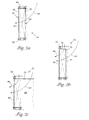
- the filter cartridge 20 includes a top cap 50 and a bottom cap 52. As best illustrated in Figure 2a, the caps 50, 52 serve to secure the first and second mesh layers 22, 26 together. The caps 50, 52 can also be used to retain the filter medium 42 in the filter cartridge 20.
- the caps 50, 52 can be constructed from a variety of materials, such as plastisol. Flexible caps constructed from plastisol or other clastomeric material enhance conformability of the filter cartridge 20 and provide a friction fit with a blower wheel.
- the first and second mesh layers 22, 26 can be constructed from a variety of polymeric or metal screens or scrims. In the embodiment illustrated in Figure 1, the first and second mesh layers 22, 26 are constructed from expanded metal. The mesh layers 22, 26 have a substantial open area of about 70% or greater. The interface 33 between the gaps 34 on the first mesh layer 22 with the second mesh layer 26 may be held together by adhesives, spot welding or a variety of other techniques.
- the size or diameter of the openings in the mesh layers 22, 26 is preferably smaller than the smallest dimension of the particles.
- agglomerated carbon can be located in the compartments 40 and heat set to form a unitized sorbent mass. Consequently, the open area of the first and second mesh layers 22, 26 can be dramatically increased. Molded carbon particle agglomerate suitable for use in the present filter cartridge 20 are disclosed in U.S. Patent No. 5,332,426 (Tang et al.).
- Figure 1b illustrates an alternate embodiment of the filter cartridge 20' having a web 35' that follows the contour of the first mesh layer 22'.
- the web 35' may be a particle filter or a scrim to assist in retaining the filter medium 42' in the compartments 40'.
- the web 35' may be useful to retain loose carbon in the compartments 40'. Preventing the filter medium 42' from escaping from the compartments 40' is important to prevent weight imbalances in the filter cartridge 22' from forming during usage.
- the web 35' is a particle filter located generally in the center of the compartments 40' and substantially surrounded by filter medium 42'
- the web 35' is located on the outer surface of mesh layer 22'.
- the filter cartridge 20' can be constructed using a variety of techniques.
- the web 35' can be bonded or laminated to the first mesh layer 22' either before or after formation of the raised portions 30'. Once the raised portions 30' are formed, the portion of the web 35' located along the gaps 34' is removed using mechanical or thermal processes. Consequently, the second mesh layer 26' is positioned directly against the first mesh layer 22' so that the flow passages 44' are substantially unimpeded by the web 35'.
- the portions of the web 35' along the gaps 34' are not removed provided the web 35' is sufficiently porous. That is, the web 35' can form a continuous layer around the filter 20'.
- FIG. 2b is a sectional view of an alternate filter cartridge 70 with a top cap 72 having one or more air flow passages 80, 81.
- Air flow passage 80 extends though the top mesh material 74 and outer mesh layer 84 of the filter cartridge 70.
- Air flow passage 81 extends through the inner mesh 77 and the outer mesh 84.
- the top cap 72 is constructed from an elastomeric material that secures outer mesh layer 84 to top mesh material 74.
- the top mesh material 74 includes a tab 75 that wraps around and is optionally attached to the inner mesh layer 77 to give the filter cartridge 70 additional structural integrity.
- FIG. 2c is a sectional view of an alternate filter cartridge 70' with a top cap 72' having one or more air flow passages 80', 81', substantially as shown in Figure 2b.
- Air flow passage 80 extend though the top mesh material 74' and outer mesh layer 84' of the filter cartridge 70'.
- the top cap 72' secures outer mesh layer 84' to top mesh material 74'.
- the top mesh material 74' extends across the center opening 86 to prevent debris from collecting in the filter cartridge 70'.
- FIG 3 is an exploded view of a filter cartridge 100 in accordance with the present invention and schematic blower system 104.
- the filter cartridge includes an inner mesh layer 112 and an outer mesh layer 114, but no end caps.
- the filter medium (not shown) is retained in the compartments by friction, adhesives and/or a variety of other mechanisms.
- the filter medium can be retained in a pouch or bag constructed from a scrim or other porous material.
- the filter cartridge 100 can be located in blower cavity 106 so that the outer filter surface 108 forms a friction fit with fan blades 110 on the blower wheel 102.
- the filter cartridge 100 may be retained to the blower wheel 102 by a variety of active removable fastening techniques including mechanical fasteners, such as clips, hooks and hook and loop fasteners, and/or retaining tabs.
- the fan blades 110 As the blower wheel 102 and attached filter cartridge 100 rotate, the fan blades 110 generate a reduced pressure condition that draws air along flow path 116 into center opening 118. The pressure differential draws air through the filter cartridge 100 and ejects it radially outward through the fan blades 110 into housing 120. As pressure within the housing 120 increases, air continues along flow path 116' through air outlet 122.
- the present filter cartridge 100 may be used as a conventional in-line filter for an HVAC system, such as disclosed in U.S. Patent No. 5,683,478 (Anonychuk).
- the filter cartridge 100 may be attached to a blower wheel 102 such as illustrated in Figure 3.
- Blower wheel 102 refers generically to any squirrel cage rotors, centrifugal rotors and the like. Clips or fasteners may be used to attached the filter cartridge 100 to the blower wheel 102, such as disclosed in commonly assigned U.S. Patent Serial No. 09/126,189, entitled Filtration System for HVAC Applications, filed June 30, 1998.
- the filter cartridge 100 preferably has a height generally equal to the height of the blower wheel 102. In an embodiment where the filter cartridge 100 has a height less than the height of the blower wheel 102, the gap defines a flow passage that permits a portion of the air flowing through the blower system 104 to bypass the filter cartridge 100.
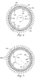
- FIG. 4 is a sectional view of a filter cartridge 130 engaged with a blower wheel 132 in accordance with the present invention.
- the arrow 131 shows the direction of rotation of the assembly 130, 132.
- Shaped inner mesh layer 134 has a series of raised portions 136 separated by gaps 140.
- Outer mesh layer 138 is positioned against the inner mesh layer 134 to form radial compartments 144.
- Filter media 142 is deposited in the radial compartments 144 formed by the raised portions 136 abutted against the outer mesh layer 138.
- the number of compartments 144 can be greater than, less than or equal to the number of blades on the blower wheel 132.
- the gaps 140 form air flow passages 146 through the filter cartridge 130. Consequently, when the filter media 142 is fully loaded, the substantially unimpeded air flow passages 146 maintain adequate air flow through the filter cartridge 130.
- the filter cartridge 130 releasably attaches to either the outside perimeter or the inside perimeter of the blower wheel 132 (see Figures 6 and 6a).
- FIG. 5 is a sectional view of an alternate filter cartridge 160 engaged with a blower wheel 162 in accordance with the present invention.
- the arrow 161 shows the direction of rotation of the assembly 160, 162.
- the raised portions 164 formed in the inner mesh layer 166 are canted or inclined so that the compartments 165 act as a extensions of the fan blades 168.
- the raised portions 164 can be canted or inclined at an angle of inclination 167 of less than about 45 degrees relative to an axis 163 normal to the filter cartridge 160.
- a cant of -45 degrees relative to axis 163 is also possible for some applications.
- the angle of inclination 167 is reversed (the filter cartridge 160 is flipped over).
- the shaping or inclination of the raised portions 164 increases the airflow though the filter cartridge 160 and blower wheel 162.
- the raised portions 164 are aligned and in-sync with the fan blades 168. As discussed in Example 4, locating the raised portions 164 out of sync with, or offset from, the fan blades 168 does not significantly diminish airflow.
- Figure 6 is a sectional view of an alternate filter cartridge 180 engaged with blower wheel 182 in accordance with the present invention.
- the embodiment of Figure 6 corresponds generally with Figure 4, except that the raised portions 184 are formed on the outer mesh layer 186.
- the inner mesh layer 188 that encloses raised portions 184 to form compartments 189 is cylindrical.
- the inner mesh layer 188 may include raised portions that may or may not be aligned with the raised portions 184 on the outer mesh layer 186.
- Figure 6a is a sectional view of an alternate filter cartridge 180' engaged with an outer perimeter of blower wheel 182' in accordance with the present invention.
- Raised portions 184' are formed on outer mesh layer 186'.
- Inner mesh layer 188' encloses raised portions 184' to form compartments 189' and engages with the outer perimeter of the blower wheel 182'.
- FIG. 7 is a top view of a filter cartridge 190 engaged with a blower wheel 192 in accordance with the present invention.
- Top cap 194 includes a series of removable weight balancing tabs 196 that can be trimmed or removed entirely to balance the blower wheel/filter cartridge assembly.
- top cap 194 may include a plurality of gaps 198 of known volume. By depositing a material of known density in the gaps 198, the same balancing procedure can be performed.
- the filter media is preferably a material having a useful level of resistance to penetration or transfer of particles and/or aerosols while retaining a desirable level of gas transport through the material. Resistance to permeation or transfer of particles and/or aerosols may be measured by determining the retention (filtration) of particles and can be expressed as clean air delivery rate (CADR), as defined in ANSI Standard AC-1-1988.
- ACR clean air delivery rate
- the filter media may be paper, porous films of thermoplastic or thermoset materials, nonwoven webs of synthetic or natural fibers, scrims, woven or knitted materials, foams, or electret or electrostatically charged materials.
- the filter media may also include sorbents, catalysts, and/or activated carbon (granules, fibers, fabric, and molded shapes).
- Electret filter webs can be formed of the split fibrillated charged fibers as described in U.S. Pat. No. Re. 30,782. These charged fibers can be formed into a nonwoven web by conventional means and optionally joined to a supporting scrim such as disclosed in U.S. Pat. No. 5,230,800 forming an outer support layer.
- the support scrim can be a spunbond web, a netting, a Claf web, or the like.
- the nonwoven fibrous filter web can be a melt blown microfiber nonwoven web, such as disclosed in U.S. Pat. No. 4,817,942 which can be joined to a support layer during web formation as disclosed in that patent, or subsequently joined to a support web in any conventional manner.
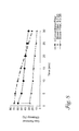
- Figure 8 shows a comparison of the gas removal efficiency of a conventional filter and two filter cartridges according to the present invention compared to a conventional cabin air filter.
- the conventional filter had about 82 grams of carbon.
- the blower filter with a diameter of about 12.95 centimeters (5.1-inches) had about 55 grams of carbon and the 11.4 centimeters (4.5-inches) diameter blower filter had about 20 grams of carbon.
- Each of the blower filters had the carbon generally equally divided among about 44 compartments (equal to the number of fan blades on the blower wheel). The compartments extended radially into the center opening of the blower wheel, as generally illustrated in Figure 4.
- the test was carried out by vaporizing toluene in a vaporization chamber and delivering the vaporized toluene in a carrier stream to a blower system without a filter cartridge.
- the amount of toluene required to deliver a concentration of 80 parts per million at a flow rate of about 200 cubic meters/hour (117 cubic feet/minute) through the blower wheel was determined.
- one of the filter cartridge described above was inserted into the blower wheel.
- Each of the filter cartridges was subjected to a toluene challenge of about 80 parts per million concentration with a flow rate of about 200 cubic meters/hour (117 cubic feet/minute). In this accelerated test about 15 minutes is roughly equal to one year of use in a car.
- the initial airflow reduction due to the blower filter is roughly equal to the 22% flow reduction of the conventional cabin air filter.
- the conventional filter airflow decreases with time, while the blower filter did not due to the non-plugging airflow passages. That is, the failure mode of the conventional air filter is a reduction in airflow, whereas the present blower filters maintain airflow even when the filter media is saturated.
- the size of the filter and the amount of media in it largely effect filter performance.
- performance matching traditional cabin air filters can be achieved.
- several other factors were found to effect performance, including the use of shaped pockets to improve airflow and an open top that improves airflow and gas removal efficiency.
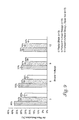
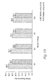
- FIG. 9 A comparison of airflow using the radial shape carbon blades and inclined or canted carbon blade is shown in the Figure 9 for various blower voltages.
- the angle of inclination for the shaped blades was about 25 degrees from an axis normal to the filter cartridge (radially inward along the flow passage).
- the Statistical bars showing the range of values are provided at the top of each bar.
- forward inclined shaped carbon blades resulted in greater airflow through the present filtration system than either the radial shaped carbon blades or backward curved shaped carbon blades.
- the greatest air flow was achieved using a filter cartridge having flow passages extending through the top cap, such as discussed in connection with Figures 2 and 2a.
- Figure 10 illustrates the result of a test to determine the effect of the incline or cant direction of the shaped carbon blades on airflow.
- the angle of inclination of the shaped blades was about 25 degrees from an axis normal to the filter cartridge. Statistical bars showing the range of values are provided at the top of each bar.
- the same filter was used for both tests. The filter was placed in the blower wheel such that the carbon pockets inclined in a backward curved (BC) configuration. The same filter was then turned over such that the carbon pockets formed a forward curved (FC) configuration. The forward curved configuration showed about an 18% improvement in airflow compared to the backward curved configuration (33% reduction vs. 27%). This test clearly shows the sensitivity of the airflow to the orientation of the carbon blades.
- a test to determine the sensitivity of the airflow to the alignment of the carbon blades with the blower wheel was carried out.
- the angle of inclination of the shaped blades was about 25 degrees from an axis normal to the filter cartridge.
- the carbon blades of the filter were aligned and in-sync with the blades of the blower wheel.
- the blades of the filter were offset about 1/88 th of a revolution to the blower wheel blades.
- the aligned in-sync case improved the airflow by about 1%. This test established that it is not necessary to provide a feature to align the filter cartridge with the blower wheel blades.
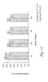
- FIG 11 illustrates the respective airflow reduction using a perforated cap and a solid cap on the filter cartridge.
- the filter cartridge had a 11.4 centimeters (4.5-inches) diameter and contained about 20 grams of carbon.
- the angle of inclination of the shaped blades was about 25 degrees from an axis normal to the filter cartridge.
- Statistical bars showing the range of values are provided at the top of each bar.
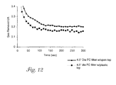
- Example 6 is directed to evaluating the gas removal efficiency of the filter cartridges tested in Example 5. As illustrated in Figure 12, the gas removal efficiency of the perforated cap design was about 4-7% higher than that of the solid cap design.
- the gas test used toluene a concentration of about 80 parts per million and a flow rate of about 200 cubic meters/hour (117 cubic feet per minute) as described in Example 1. This test was carried out several times with the same result.
Landscapes
- Chemical Kinetics & Catalysis (AREA)
- Chemical & Material Sciences (AREA)
- Engineering & Computer Science (AREA)
- Mechanical Engineering (AREA)
- General Engineering & Computer Science (AREA)
- Geometry (AREA)
- Physics & Mathematics (AREA)
- Filtering Of Dispersed Particles In Gases (AREA)
- Air-Conditioning For Vehicles (AREA)
- Automatic Disk Changers (AREA)
- Steering Control In Accordance With Driving Conditions (AREA)
- Structures Of Non-Positive Displacement Pumps (AREA)
- Cigarettes, Filters, And Manufacturing Of Filters (AREA)
- Separation Of Gases By Adsorption (AREA)
- Electrostatic Separation (AREA)
Abstract
Description
- The present invention relates to a filtration system releasably attachable to a blower wheel in an HVAC system, and in particular, to a filter cartridge having a plurality of compartments containing a filter medium and a plurality of substantially unimpeded air flow passages that maintain a high flow rate even when the filter medium is in a fully loaded state.
- With increased concern over environmental air quality, innovative solutions have been sought for adding filtration capacity to new and existing air circulation systems, such as heating, ventilation, and cooling systems (HVAC) for buildings and vehicles. For example, the HVAC systems in most vehicles do not include air filters. Minimal space is generally available for retrofitting a filter to the HVAC system. Moreover, it may be necessary to provide one filter for incoming air and a second filter for air recirculating within the passenger compartment. Even on new vehicles, space within the HVAC system is at a premium and it is difficult for some manufacturers to provide a location for an appropriate filter.
- In addition to the difficulty of finding sufficient space for a filter, the failure mode of most filter media also raises concerns. Over time, environmental contaminants accumulate in filters, typically resulting in a reduced flow rate through the air circulation system. Failure to replace the filter media periodically can result in an increased static air pressure drop across the filter and reduced efficiency for the air circulation system. The reduced flow rate through a loaded filter can also create safety hazards, such as allowing insufficient airflow for operating the defrost system of an HVAC system.
- One approach to retrofitting an air filter to an HVAC system of a vehicle is disclosed in U.S. Patent No. 5,683,478 (Anonychuk). The air filter is sized and shaped to fit into a cavity located within a blower motor assembly. An outwardly extended lip is provided on the base of the air filter for rigid attachment to a rim located below the fan on the automobile. The fan in the blower motor assembly rotates around the stationary filter. Although the '478 patent recognizes the need to provide filtration efficiency without impeding airflow, air flow will inevitably be reduced as the filter becomes loaded with environmental contaminants. The failure mode of the filter element may be an unacceptable reduction in airflow through the blower motor assembly.
- U.S. Patent No. 5,265,348 (Fleishman et al.) discloses the use of a rotating foam material on a rotary fan to reduce noise.
- Various filters for blower wheels are disclosed in commonly assigned U.S. Patent Applications Nos. 09/126,189, entitled Filtration System for HVAC Applications; 09/126,190, entitled Moving Sorbent Filter Device; and 09/126,181, entitled Moving Filter Device having Filter Elements with Flow Passages and Method of Filtering Air, all filed on July 30, 1998.
- The present invention is directed to a filtration system attachable to a blower wheel in an HVAC system. The present filtration system is particularly useful to provide cabin air filtration to vehicles, which currently do not have a filter designed in the HVAC system. Movement of the filter cartridge with the blower wheel increases filtration efficiency during blower operation. The present moving filter cartridge can be retrofitted to most existing blower wheels. The filter cartridge releasably attaches to either the outside perimeter or the inside perimeter of the blower wheel.
- An advantage of the present filtration system is that it is retrofittable into most existing vehicles. Since most cars have a blower wheel, a space exists to place the present filter cartridge. On the other hand, it is not feasible to easily retrofit a vehicle with a conventional cabin air filter since little additional space is available. Locating the filter cartridge at the blower wheel provides filtration of both outside air entering the HVAC system and air being recirculated within the system. Most cabin air filters only filter the air as it enters the vehicle.
- The present filter cartridge includes both compartments containing a filter medium and flow passages of a size, density and shape such that a high flow rate is maintained even when the filter media is fully loaded. The spinning action of the filter cartridge causes the filter medium contained in the compartments to impact air as it passes through the flow passages. Some loss of filtration efficiency due the flow passages is offset by increased efficiency due to the movement of the filter cartridge with the blower wheel.
- The filtration system rotates in conjunction with a blower wheel. The blower wheel has a plurality of fan blades arranged in a spaced relationship radially around a blower cavity. The blower wheel defines a flow path extending radially outward from the blower cavity and through the fan blades when the blower wheel is rotating. The present filtration system can reduce the airflow through the blower wheel, thereby reducing the power consumption of the motor. The relationship between power and flow is a cubic function. By reducing the load (i.e., power consumption), the life of the motor is extended.
- In one embodiment, the filter cartridge comprises a mesh structure forming a generally annular cylinder comprising a center opening, a plurality of compartments containing a filter medium, and spaces between the compartments. The spaces between the compartments comprise substantially unimpeded airflow passages that permit airflow even when the filter medium is fully loaded.
- The compartments may extend radially into the center opening. In one embodiment, the compartments comprise one of corrugations or pleats in one or more of the mesh layers. The compartments can be shaped to operate as fan blades. The compartments are typically discrete pockets. The mesh typically comprises an expanded metal screen. In one embodiment, a mesh material extends across a top opening of the annular cylinder. The filter medium can be selected from a group consisting of electret charged medium, particulate medium, sorbents medium, agglomerated carbon or combinations thereof.
- The filter cartridge comprises at least one end cap. An air flow passage can optionally extends through the at least one end cap. The end cap can also include weight balancing cavities and/or removable weight balancing tabs.
- In another embodiment, the filter cartridge comprises a first mesh layer having a plurality of raised portions and a second mesh layer engaged with the first mesh layer such that the raised portions comprise compartments. A filter medium is retained in the compartments. Spaces between the compartments comprise substantially unimpeded airflow passages that permit airflow even when the filter medium is fully loaded. The filter medium is preferably agglomerated carbon or other filter medium such as activated carbon or other sorbents materials that remove odors and gases from the air, such as diesel exhaust, car exhaust, urban or farm smells, carbon monoxide, and ozone.
-
- Figure 1 is a perspective view of a filter cartridge in accordance with the present invention.
- Figure 1a is a sectional top view of the filter cartridge of Figure 1.
- Figure 1b is a sectional top view of an alternate filter cartridge in accordance with the present invention.
- Figure 2a is a sectional view of the filter cartridge of Figure 1.
- Figure 2b is a sectional view of an alternate filter cartridge in accordance with the present invention.
- Figure 2c is a sectional view of another alternate filter cartridge in accordance with the present invention.
- Figure 3 is a perspective view of a filter cartridge engaged with a blower wheel in accordance with the present invention.
- Figure 4 is a sectional view of a filter cartridge engaged with a blower wheel in accordance with the present invention.
- Figure 5 is a sectional view of an alternate filter cartridge engaged with a blower wheel in accordance with the present invention.
- Figure 6 is a sectional view of another alternate filter cartridge engaged with a blower wheel in accordance with the present invention.
- Figure 6a is a sectional view of a filter cartridge engaged with an outer perimeter of a blower wheel in accordance with the present invention.
- Figure 7 is a top view of a filter cartridge engaged with a blower wheel in accordance with the present invention.
- Figure 8 is a graphic representation of data relating to gas removal efficiency of the present filter cartridges and a conventional filter cartridge.
- Figure 9 is a graphic representation of data relating to shaped blade inclination on airflow performance.
- Figure 10 is a graphic representation of data relating to shaped blade orientation on airflow performance.
- Figure 11 is a graphic representation of data relating to permeability of the filter cartridge cap on airflow performance.
- Figure 12 is a graphic representation of data relating to permeability of the filter cartridge cap on gas removal efficiency.
- Figure 13 is a graphic representation of data relating to permeability of the filter cartridge cap on airflow performance.
-
- Figures 1, 1a and 2a illustrate a
filter cartridge 20 in accordance with the present invention. Thefilter cartridge 20 includes afirst mesh layer 22 defining aninner filter surface 24 and asecond mesh layer 26 defining anouter filter surface 28. Thefirst mesh layer 22 includes a plurality of raisedportions 30 that protrude into center opening 32 of thefilter cartridge 20. Gaps orspaces 34 located between the raisedportions 30 on thefirst mesh layer 22 are abutted against thesecond mesh layer 26 so that the raisedportions 30 define a plurality ofcompartments 40. Thecompartments 40 are preferably filled with a filter medium 42 (see e.g., Figure 1a). In the illustrated embodiment, each of thecompartments 40 define a discrete pocket that does not communicate with the adjacent compartments. In an alternate embodiment, thecompartments 40 can be formed in a single mesh layer, obviating the second mesh layer. - The gaps or
spaces 34 between thecompartments 40 compriseair flow passages 44 that allow for high initial air flow through thefilter cartridge 20, that does not decrease over time. That is, theair flow passages 44 are substantially unimpeded when thefilter medium 42 is fully loaded. - The
filter cartridge 20 includes atop cap 50 and abottom cap 52. As best illustrated in Figure 2a, thecaps caps filter medium 42 in thefilter cartridge 20. Thecaps filter cartridge 20 and provide a friction fit with a blower wheel. - The first and second mesh layers 22, 26 can be constructed from a variety of polymeric or metal screens or scrims. In the embodiment illustrated in Figure 1, the first and second mesh layers 22, 26 are constructed from expanded metal. The mesh layers 22, 26 have a substantial open area of about 70% or greater. The
interface 33 between thegaps 34 on thefirst mesh layer 22 with thesecond mesh layer 26 may be held together by adhesives, spot welding or a variety of other techniques. - When using loose
particle filter media 42, the size or diameter of the openings in the mesh layers 22, 26 is preferably smaller than the smallest dimension of the particles. Alternatively, agglomerated carbon can be located in thecompartments 40 and heat set to form a unitized sorbent mass. Consequently, the open area of the first and second mesh layers 22, 26 can be dramatically increased. Molded carbon particle agglomerate suitable for use in thepresent filter cartridge 20 are disclosed in U.S. Patent No. 5,332,426 (Tang et al.). - Figure 1b illustrates an alternate embodiment of the filter cartridge 20' having a web 35' that follows the contour of the first mesh layer 22'. The web 35' may be a particle filter or a scrim to assist in retaining the filter medium 42' in the compartments 40'. For example, the web 35' may be useful to retain loose carbon in the compartments 40'. Preventing the filter medium 42' from escaping from the compartments 40' is important to prevent weight imbalances in the filter cartridge 22' from forming during usage. In another embodiment, the web 35' is a particle filter located generally in the center of the compartments 40' and substantially surrounded by filter medium 42' In yet another embodiment, the web 35' is located on the outer surface of mesh layer 22'.
- The filter cartridge 20' can be constructed using a variety of techniques. For example, the web 35' can be bonded or laminated to the first mesh layer 22' either before or after formation of the raised portions 30'. Once the raised portions 30' are formed, the portion of the web 35' located along the gaps 34' is removed using mechanical or thermal processes. Consequently, the second mesh layer 26' is positioned directly against the first mesh layer 22' so that the flow passages 44' are substantially unimpeded by the web 35'. In another embodiment, the portions of the web 35' along the gaps 34' are not removed provided the web 35' is sufficiently porous. That is, the web 35' can form a continuous layer around the filter 20'.
- Figure 2b is a sectional view of an
alternate filter cartridge 70 with atop cap 72 having one or moreair flow passages Air flow passage 80 extends though thetop mesh material 74 andouter mesh layer 84 of thefilter cartridge 70.Air flow passage 81 extends through theinner mesh 77 and theouter mesh 84. Thetop cap 72 is constructed from an elastomeric material that securesouter mesh layer 84 totop mesh material 74. Thetop mesh material 74 includes atab 75 that wraps around and is optionally attached to theinner mesh layer 77 to give thefilter cartridge 70 additional structural integrity. - Figure 2c is a sectional view of an alternate filter cartridge 70' with a top cap 72' having one or more air flow passages 80', 81', substantially as shown in Figure 2b.
Air flow passage 80 extend though the top mesh material 74' and outer mesh layer 84' of the filter cartridge 70'. The top cap 72' secures outer mesh layer 84' to top mesh material 74'. In the embodiment of Figure 2c, the top mesh material 74' extends across the center opening 86 to prevent debris from collecting in the filter cartridge 70'. - Figure 3 is an exploded view of a
filter cartridge 100 in accordance with the present invention andschematic blower system 104. The filter cartridge includes aninner mesh layer 112 and an outer mesh layer 114, but no end caps. In the embodiment of Figure 3, the filter medium (not shown) is retained in the compartments by friction, adhesives and/or a variety of other mechanisms. For example, the filter medium can be retained in a pouch or bag constructed from a scrim or other porous material. - The
filter cartridge 100 can be located inblower cavity 106 so that theouter filter surface 108 forms a friction fit withfan blades 110 on theblower wheel 102. Alternatively, thefilter cartridge 100 may be retained to theblower wheel 102 by a variety of active removable fastening techniques including mechanical fasteners, such as clips, hooks and hook and loop fasteners, and/or retaining tabs. - As the
blower wheel 102 and attachedfilter cartridge 100 rotate, thefan blades 110 generate a reduced pressure condition that draws air alongflow path 116 intocenter opening 118. The pressure differential draws air through thefilter cartridge 100 and ejects it radially outward through thefan blades 110 intohousing 120. As pressure within thehousing 120 increases, air continues along flow path 116' throughair outlet 122. - The
present filter cartridge 100 may be used as a conventional in-line filter for an HVAC system, such as disclosed in U.S. Patent No. 5,683,478 (Anonychuk). Alternatively, thefilter cartridge 100 may be attached to ablower wheel 102 such as illustrated in Figure 3.Blower wheel 102 refers generically to any squirrel cage rotors, centrifugal rotors and the like. Clips or fasteners may be used to attached thefilter cartridge 100 to theblower wheel 102, such as disclosed in commonly assigned U.S. Patent Serial No. 09/126,189, entitled Filtration System for HVAC Applications, filed June 30, 1998. Thefilter cartridge 100 preferably has a height generally equal to the height of theblower wheel 102. In an embodiment where thefilter cartridge 100 has a height less than the height of theblower wheel 102, the gap defines a flow passage that permits a portion of the air flowing through theblower system 104 to bypass thefilter cartridge 100. - Figure 4 is a sectional view of a
filter cartridge 130 engaged with ablower wheel 132 in accordance with the present invention. Thearrow 131 shows the direction of rotation of theassembly inner mesh layer 134 has a series of raisedportions 136 separated bygaps 140.Outer mesh layer 138 is positioned against theinner mesh layer 134 to form radial compartments 144.Filter media 142 is deposited in theradial compartments 144 formed by the raisedportions 136 abutted against theouter mesh layer 138. The number ofcompartments 144 can be greater than, less than or equal to the number of blades on theblower wheel 132. - The
gaps 140 formair flow passages 146 through thefilter cartridge 130. Consequently, when thefilter media 142 is fully loaded, the substantially unimpededair flow passages 146 maintain adequate air flow through thefilter cartridge 130. Thefilter cartridge 130 releasably attaches to either the outside perimeter or the inside perimeter of the blower wheel 132 (see Figures 6 and 6a). - Figure 5 is a sectional view of an
alternate filter cartridge 160 engaged with ablower wheel 162 in accordance with the present invention. Thearrow 161 shows the direction of rotation of theassembly portions 164 formed in theinner mesh layer 166 are canted or inclined so that thecompartments 165 act as a extensions of thefan blades 168. The raisedportions 164 can be canted or inclined at an angle ofinclination 167 of less than about 45 degrees relative to anaxis 163 normal to thefilter cartridge 160. A cant of -45 degrees relative toaxis 163 is also possible for some applications. In an embodiment where thefilter cartridge 160 is attached to the outside perimeter of theblower wheel 162, the angle ofinclination 167 is reversed (thefilter cartridge 160 is flipped over). - Maintaining high airflow in the blower system is critical to effectively heat and cool the cabin of a vehicle. The shaping or inclination of the raised
portions 164 increases the airflow though thefilter cartridge 160 andblower wheel 162. In the embodiment of Figure 5, the raisedportions 164 are aligned and in-sync with thefan blades 168. As discussed in Example 4, locating the raisedportions 164 out of sync with, or offset from, thefan blades 168 does not significantly diminish airflow. - Figure 6 is a sectional view of an
alternate filter cartridge 180 engaged withblower wheel 182 in accordance with the present invention. The embodiment of Figure 6 corresponds generally with Figure 4, except that the raisedportions 184 are formed on theouter mesh layer 186. Theinner mesh layer 188 that encloses raisedportions 184 to formcompartments 189 is cylindrical. In an alternate embodiment, theinner mesh layer 188 may include raised portions that may or may not be aligned with the raisedportions 184 on theouter mesh layer 186. - Figure 6a is a sectional view of an alternate filter cartridge 180' engaged with an outer perimeter of blower wheel 182' in accordance with the present invention. Raised portions 184' are formed on outer mesh layer 186'. Inner mesh layer 188' encloses raised portions 184' to form compartments 189' and engages with the outer perimeter of the blower wheel 182'.
- Figure 7 is a top view of a
filter cartridge 190 engaged with a blower wheel 192 in accordance with the present invention.Top cap 194 includes a series of removableweight balancing tabs 196 that can be trimmed or removed entirely to balance the blower wheel/filter cartridge assembly. Alternatively,top cap 194 may include a plurality ofgaps 198 of known volume. By depositing a material of known density in thegaps 198, the same balancing procedure can be performed. - The filter media is preferably a material having a useful level of resistance to penetration or transfer of particles and/or aerosols while retaining a desirable level of gas transport through the material. Resistance to permeation or transfer of particles and/or aerosols may be measured by determining the retention (filtration) of particles and can be expressed as clean air delivery rate (CADR), as defined in ANSI Standard AC-1-1988.
- The filter media may be paper, porous films of thermoplastic or thermoset materials, nonwoven webs of synthetic or natural fibers, scrims, woven or knitted materials, foams, or electret or electrostatically charged materials. The filter media may also include sorbents, catalysts, and/or activated carbon (granules, fibers, fabric, and molded shapes). Electret filter webs can be formed of the split fibrillated charged fibers as described in U.S. Pat. No. Re. 30,782. These charged fibers can be formed into a nonwoven web by conventional means and optionally joined to a supporting scrim such as disclosed in U.S. Pat. No. 5,230,800 forming an outer support layer. The support scrim can be a spunbond web, a netting, a Claf web, or the like. Alternatively, the nonwoven fibrous filter web can be a melt blown microfiber nonwoven web, such as disclosed in U.S. Pat. No. 4,817,942 which can be joined to a support layer during web formation as disclosed in that patent, or subsequently joined to a support web in any conventional manner.
- The performance of the present filter cartridge was tested and compared to a conventional stationary cabin air filter made by Minnesota Mining and Manufacturing Company. Figure 8 shows a comparison of the gas removal efficiency of a conventional filter and two filter cartridges according to the present invention compared to a conventional cabin air filter. The conventional filter had about 82 grams of carbon. The blower filter with a diameter of about 12.95 centimeters (5.1-inches) had about 55 grams of carbon and the 11.4 centimeters (4.5-inches) diameter blower filter had about 20 grams of carbon. Each of the blower filters had the carbon generally equally divided among about 44 compartments (equal to the number of fan blades on the blower wheel). The compartments extended radially into the center opening of the blower wheel, as generally illustrated in Figure 4.
- The test was carried out by vaporizing toluene in a vaporization chamber and delivering the vaporized toluene in a carrier stream to a blower system without a filter cartridge. The amount of toluene required to deliver a concentration of 80 parts per million at a flow rate of about 200 cubic meters/hour (117 cubic feet/minute) through the blower wheel was determined. After the concentration of toluene was determined, one of the filter cartridge described above was inserted into the blower wheel.
- Each of the filter cartridges was subjected to a toluene challenge of about 80 parts per million concentration with a flow rate of about 200 cubic meters/hour (117 cubic feet/minute). In this accelerated test about 15 minutes is roughly equal to one year of use in a car. The initial airflow reduction due to the blower filter is roughly equal to the 22% flow reduction of the conventional cabin air filter. However, the conventional filter airflow decreases with time, while the blower filter did not due to the non-plugging airflow passages. That is, the failure mode of the conventional air filter is a reduction in airflow, whereas the present blower filters maintain airflow even when the filter media is saturated.
- The size of the filter and the amount of media in it largely effect filter performance. By using a slightly larger diameter blower filter, performance matching traditional cabin air filters can be achieved. However, during the design or optimization of the blower filter several other factors were found to effect performance, including the use of shaped pockets to improve airflow and an open top that improves airflow and gas removal efficiency.
- A comparison of airflow using the radial shape carbon blades and inclined or canted carbon blade is shown in the Figure 9 for various blower voltages. The angle of inclination for the shaped blades was about 25 degrees from an axis normal to the filter cartridge (radially inward along the flow passage). The Statistical bars showing the range of values are provided at the top of each bar. At all blower voltages, forward inclined shaped carbon blades resulted in greater airflow through the present filtration system than either the radial shaped carbon blades or backward curved shaped carbon blades. The greatest air flow was achieved using a filter cartridge having flow passages extending through the top cap, such as discussed in connection with Figures 2 and 2a.
- Figure 10 illustrates the result of a test to determine the effect of the incline or cant direction of the shaped carbon blades on airflow. The angle of inclination of the shaped blades was about 25 degrees from an axis normal to the filter cartridge. Statistical bars showing the range of values are provided at the top of each bar. The same filter was used for both tests. The filter was placed in the blower wheel such that the carbon pockets inclined in a backward curved (BC) configuration. The same filter was then turned over such that the carbon pockets formed a forward curved (FC) configuration. The forward curved configuration showed about an 18% improvement in airflow compared to the backward curved configuration (33% reduction vs. 27%). This test clearly shows the sensitivity of the airflow to the orientation of the carbon blades.
- A test to determine the sensitivity of the airflow to the alignment of the carbon blades with the blower wheel was carried out. The angle of inclination of the shaped blades was about 25 degrees from an axis normal to the filter cartridge. In one case the carbon blades of the filter were aligned and in-sync with the blades of the blower wheel. In the second case the blades of the filter were offset about 1/88th of a revolution to the blower wheel blades. The aligned in-sync case improved the airflow by about 1%. This test established that it is not necessary to provide a feature to align the filter cartridge with the blower wheel blades.
- Although some type of top cap is typically required to locate the filter in the blower and to hold the carbon in place, it does not necessarily need to be a closed ring. Figure 11 illustrates the respective airflow reduction using a perforated cap and a solid cap on the filter cartridge. The filter cartridge had a 11.4 centimeters (4.5-inches) diameter and contained about 20 grams of carbon. The angle of inclination of the shaped blades was about 25 degrees from an axis normal to the filter cartridge. Statistical bars showing the range of values are provided at the top of each bar. By using a perforated metal cap (about 70% open), the airflow of the filter was increased about 4% at various blower voltages.
- Example 6 is directed to evaluating the gas removal efficiency of the filter cartridges tested in Example 5. As illustrated in Figure 12, the gas removal efficiency of the perforated cap design was about 4-7% higher than that of the solid cap design. The gas test used toluene a concentration of about 80 parts per million and a flow rate of about 200 cubic meters/hour (117 cubic feet per minute) as described in Example 1. This test was carried out several times with the same result.
- One possible explanation for the lower efficiency of the solid cap design is that the carbon located directly beneath the solid cap is not subject to much airflow. To determine if this was true, a test was conducted on a 11.4 centimeters (4.5-inches) diameter filter with 20 grams of carbon. The angle of inclination of the shaped blades was about 25 degrees from an axis normal to the filter cartridge. The same filter was used for tests with and without top caps. The filter was first tested without a top cap. A series of masking tape strips, about 2.54 millimeters (0.10 inches) in width were wrapped around the circumference of the filter beginning at the top. The open top filter showed a linear decrease in flow as progressive widths of tape masked the filter. The results are presented in Figure 13.
- The same filter was then capped and the test was repeated. This test showed that masking off about the top 5.1 millimeters (0.20 inches) of the filter with a cap did not effect the airflow, indicating that the cap was preventing air from passing through this region of the filter (see Figure 13). Carbon located in the region below the cap filter was apparently not filtering due to the lack of flow. In a filter with about 20 grams of carbon, the cap may be blocking as much as about 2.5 grams (more than 10%) of the carbon. Consequently, it appears that the open cap design has both higher airflow and efficiency than the equivalent design with a solid cap.
Claims (13)
- A filter cartridge comprising a mesh structure forming a generally annular cylinder comprising a center opening, the mesh structure further forming a plurality of compartments, which compartments contain a filter medium, and spaces between the compartments, the spaces between the compartments comprising substantially unimpeded air flow passages that permit airflow even when the filter medium is fully loaded.
- The filter cartridge of claim 1 wherein the compartments extend generally radially toward the center opening.
- The filter cartridge of claim 1 wherein the compartments are shaped to operate as fan blades.
- The filter cartridge of claim 1 wherein the compartments comprise discrete pockets.
- The filter cartridge of claim 1 wherein the filter cartridge comprises at least one end cap with an air flow passage extending through the at least one end cap and at least one end cap comprises weight balancing cavities.
- The filter cartridge of claim 5 wherein the at least one end cap comprises removable weight balancing tabs.
- The filter cartridge of claim 1 wherein the filter medium is selected from a group consisting of electret charged medium, particulate medium, sorbents medium, agglomerated carbon or combinations thereof.
- The filter cartridge of claim 1 comprising a mesh material extending across a top opening of the annular cylinder.
- A filter cartridge of claim 1
wherein the mesh structure, comprises a first mesh layer having a plurality of raised portions and a second mesh layer engaged with the first mesh layer such that the raised portions comprise compartments; and
spaces between the raised portions forming the substantially unimpeded air flow passages that permit airflow even when the filter medium is fully loaded. - A filtration system comprising a filter cartridge that rotates in conjunction with a blower wheel, the blower wheel having a plurality of fan blades arranged in a spaced relationship radially around a blower cavity to define a flow path extending radially outward from the blower cavity through the fan blades when the blower wheel is rotating,
the filter cartridge being releasably attachable to the blower wheel in an engaged configuration, the filter cartridge comprising a mesh structure having a center opening and a mesh surface configured to be generally adjacent to the fan blades and to extend across at least a portion of the flow path when in the engaged configuration, the mesh structure comprising a plurality of compartments containing a filter medium and a plurality of substantially unimpeded air flow passages that permit airflow even when the filter medium is fully loaded. - The system of claim 10 wherein the mesh structure comprises a first mesh layer having a plurality of raised portions and a second mesh layer engaged with the first mesh layer such that the raised portions comprise the compartments and spaces between the raised portions comprise the air flow passages.
- The system of claim 10 wherein the filter cartridge comprises an annular cylinder with at least one end cap with an air flow passage extending through the at least one end cap.
- The system of claim 12 wherein the at least one end cap comprises weight balancing cavities.
Applications Claiming Priority (3)
| Application Number | Priority Date | Filing Date | Title |
|---|---|---|---|
| US504474 | 2000-02-16 | ||
| US09/504,474 US6348086B1 (en) | 2000-02-16 | 2000-02-16 | Combination blower wheel and filter cartridge system for HVAC applications |
| PCT/US2000/018783 WO2001060497A1 (en) | 2000-02-16 | 2000-07-10 | Filter cartridge and combination of blower wheel and filter cartridge |
Publications (2)
| Publication Number | Publication Date |
|---|---|
| EP1257342A1 EP1257342A1 (en) | 2002-11-20 |
| EP1257342B1 true EP1257342B1 (en) | 2004-06-09 |
Family
ID=24006431
Family Applications (1)
| Application Number | Title | Priority Date | Filing Date |
|---|---|---|---|
| EP00947174A Expired - Lifetime EP1257342B1 (en) | 2000-02-16 | 2000-07-10 | Filter cartridge and combination of blower wheel and filter cartridge |
Country Status (11)
| Country | Link |
|---|---|
| US (1) | US6348086B1 (en) |
| EP (1) | EP1257342B1 (en) |
| JP (1) | JP2003523820A (en) |
| KR (1) | KR100760058B1 (en) |
| AT (1) | ATE268632T1 (en) |
| AU (1) | AU2000260829A1 (en) |
| CA (1) | CA2399430A1 (en) |
| DE (1) | DE60011476T2 (en) |
| ES (1) | ES2220494T3 (en) |
| TW (1) | TW527207B (en) |
| WO (1) | WO2001060497A1 (en) |
Cited By (1)
| Publication number | Priority date | Publication date | Assignee | Title |
|---|---|---|---|---|
| CN110523153A (en) * | 2019-09-29 | 2019-12-03 | 新昌县大菠萝农业发展有限公司 | A kind of removable easy clean filter core of spinning |
Families Citing this family (49)
| Publication number | Priority date | Publication date | Assignee | Title |
|---|---|---|---|---|
| AU761797B2 (en) * | 2000-05-29 | 2003-06-12 | Heru Prasanta Wijaya | Air guided filter for internal combustion engine |
| JP2003001028A (en) * | 2001-06-22 | 2003-01-07 | Bridgestone Corp | Filter material |
| US6517612B1 (en) * | 2001-10-29 | 2003-02-11 | Gore Enterprise Holdings, Inc. | Centrifugal filtration device |
| JP3942887B2 (en) * | 2001-12-26 | 2007-07-11 | 株式会社日本自動車部品総合研究所 | Evaporative fuel adsorbent and air cleaner |
| US20040163372A1 (en) * | 2003-02-25 | 2004-08-26 | Nguyen Ledu Q. | Environmentally friendly air filter for an internal combustion engine |
| US6905536B2 (en) * | 2003-06-11 | 2005-06-14 | Arvin Technologies, Inc. | Increased surface area hydrocarbon adsorber |
| US7070641B1 (en) * | 2003-12-03 | 2006-07-04 | Fleetguard, Inc. | Carbon media filter element |
| DE102004000050B4 (en) * | 2004-11-17 | 2008-07-31 | Mann + Hummel Gmbh | Filter element, in particular cabin filter, to the frontal flow |
| SE528750C2 (en) * | 2005-06-27 | 2007-02-06 | 3Nine Ab | Method and apparatus for separating particles from a gas stream |
| US20070148051A1 (en) * | 2005-09-09 | 2007-06-28 | Dainihon Jochugiku Co., Ltd. | Chemical volatilization device |
| US20070112418A1 (en) | 2005-11-14 | 2007-05-17 | Boston Scientific Scimed, Inc. | Stent with spiral side-branch support designs |
| US7455504B2 (en) * | 2005-11-23 | 2008-11-25 | Hill Engineering | High efficiency fluid movers |
| US7914263B2 (en) * | 2007-05-14 | 2011-03-29 | Vladimir Berger | Ejector-type rotary device |
| JP2009011760A (en) * | 2007-07-12 | 2009-01-22 | Soft99 Corporation | Aroma deodorization device |
| US7833303B1 (en) | 2007-08-08 | 2010-11-16 | Charles George Higgins | Sifting apparatus with filter rotation and particle collection |
| CN101347699B (en) * | 2008-09-01 | 2011-08-17 | 丁琳 | Dry dust collector for soot cleaning with disrotatory filter drum and exterior air sword |
| KR100912712B1 (en) * | 2009-04-01 | 2009-08-19 | 유미소 | Centrifugal Filtration Device |
| US9795913B1 (en) * | 2009-06-26 | 2017-10-24 | Exact Corporation | System for removing particles from an air stream |
| USD652497S1 (en) * | 2010-04-30 | 2012-01-17 | R2C Performance Products, LLC. | Air filter for vehicle motor |
| CN102397841B (en) * | 2011-11-28 | 2013-08-21 | 河南省康星药业股份有限公司 | Bidirectional airflow submicron powder sorting machine |
| EP2614870B1 (en) | 2012-01-11 | 2014-03-19 | ABB Oy | Apparatus and method for removing dirt from gas flow |
| JP5899417B2 (en) * | 2012-01-19 | 2016-04-06 | パナソニックIpマネジメント株式会社 | Range food |
| US9700821B2 (en) | 2013-03-15 | 2017-07-11 | Illinois Tool Works Inc. | Portable industrial air filtration device |
| USD737945S1 (en) * | 2013-03-15 | 2015-09-01 | Illinois Tool Works Inc. | Filter |
| USD737946S1 (en) * | 2013-03-15 | 2015-09-01 | Illinois Tool Works Inc. | Filter for an air filtration device |
| USD732647S1 (en) | 2013-03-15 | 2015-06-23 | Illinois Tool Works Inc. | Air filtration device |
| AU2014262583B2 (en) * | 2013-05-09 | 2017-03-16 | The Procter & Gamble Company | Air filtering device |
| US9970351B2 (en) * | 2013-11-19 | 2018-05-15 | Cummins Filtration Ip, Inc. | High frequency silencer for an air induction system |
| KR101442071B1 (en) * | 2013-12-10 | 2014-11-04 | 코리아에프티 주식회사 | Adsorption means of gas for vehicles |
| USD758558S1 (en) | 2014-03-10 | 2016-06-07 | Illinois Tool Works Inc. | Air filtration device |
| US9517428B2 (en) | 2014-09-12 | 2016-12-13 | Illinois Tool Works Inc. | Filter for a portable industrial air filtration device |
| USD761946S1 (en) | 2014-09-12 | 2016-07-19 | Illinois Tool Works Inc. | Filter for an air filtration device |
| USD768277S1 (en) * | 2015-07-14 | 2016-10-04 | The Sy-Klone Company | Filter cartridge for air cleaner |
| USD768833S1 (en) * | 2015-07-14 | 2016-10-11 | The Sy-Klone Company | Filter cartridge for air cleaner |
| USD767746S1 (en) * | 2015-07-14 | 2016-09-27 | The Sy-Klone Company | Filter cartridge for air cleaner |
| CN105398285B (en) * | 2015-12-16 | 2018-04-10 | 王晓佩 | A kind of wheel hub and method for cutting down particulate in air content |
| DE102017115753A1 (en) * | 2017-07-13 | 2019-01-17 | Makita Corporation | Carburetor assembly, arrangement with an air filter and a carburetor assembly and internal combustion engine and engine tool |
| CN107990475A (en) * | 2017-11-23 | 2018-05-04 | 成都欧林生物科技股份有限公司 | A kind of indoor ventilation system |
| USD992710S1 (en) * | 2019-05-02 | 2023-07-18 | Dyson Technology Limited | Evaporator for a humidifier |
| CN110227311B (en) * | 2019-05-17 | 2024-01-09 | 美埃(中国)环境科技股份有限公司 | Filter |
| US11395984B2 (en) | 2019-05-24 | 2022-07-26 | Flory Industries | Dust control system and related methods |
| KR102171046B1 (en) * | 2020-05-12 | 2020-10-28 | 아이투엠 주식회사 | An Air Purifying Device |
| DE102020131838A1 (en) | 2020-12-01 | 2022-06-02 | Erich Buhl | air purification device |
| TWI728943B (en) * | 2020-12-21 | 2021-05-21 | 濾能股份有限公司 | Filter mesh frame, filter mesh structure and method for using the same |
| KR102588387B1 (en) * | 2021-02-17 | 2023-10-11 | 현대트랜시스 주식회사 | Air conditioning assembly of vehicle seat |
| WO2022231045A1 (en) * | 2021-04-30 | 2022-11-03 | 아이투엠 주식회사 | Fan blade for air purification |
| WO2022265122A1 (en) * | 2021-06-14 | 2022-12-22 | 아이투엠 주식회사 | Air purifier having fan blade installed therein |
| TWI825681B (en) * | 2022-04-19 | 2023-12-11 | 宏碁股份有限公司 | Centrifugal heat dissipation fan |
| KR102869989B1 (en) * | 2022-12-21 | 2025-10-22 | 주식회사 이엠솔루션 | Voc absorption-desorption apparatus for volatile organic compound condessing system |
Family Cites Families (30)
| Publication number | Priority date | Publication date | Assignee | Title |
|---|---|---|---|---|
| FR1500667A (en) * | 1965-11-24 | 1967-11-03 | Knecht Filterwerke Gmbh | Ventilation device for ventilating the interior of motor vehicles |
| DE2219846A1 (en) * | 1972-04-22 | 1973-10-31 | Haas & Sohn Ernst W | AIR PURIFIER, PRESENTLY FOR ROOM AIR CLEANING |
| NL160303C (en) * | 1974-03-25 | 1979-10-15 | Verto Nv | METHOD FOR MANUFACTURING A FIBER FILTER |
| US3877907A (en) * | 1974-06-13 | 1975-04-15 | Howard E Elliff | Air swirling unit for air filters on internal combustion engines |
| US3941034A (en) * | 1974-07-11 | 1976-03-02 | Carl Helwig | Filter attachment for automobile passenger compartment air intake |
| US4130487A (en) * | 1976-04-05 | 1978-12-19 | Process Scientific Innovations Ltd. | Filters for liquids or gases |
| DE2844770A1 (en) * | 1978-10-13 | 1980-04-24 | Hoelter Heinz | Flexible automobile dashboard filter - with shaped sections of catalyst material in pad of chemisorbent filling |
| US4589892A (en) * | 1983-04-07 | 1986-05-20 | Bry-Air, Inc. | Sequenced modular bed carousel dehumidifier |
| FR2581744B1 (en) * | 1985-05-10 | 1987-07-24 | Begon Jean | SAFETY FENCING BLADE |
| JPS63162022A (en) * | 1986-12-26 | 1988-07-05 | Kaken Pharmaceut Co Ltd | Material for dehumidification |
| JPS63205115A (en) * | 1987-02-21 | 1988-08-24 | Matsushita Electric Works Ltd | Air cleaner |
| GB2232094B (en) * | 1989-05-26 | 1994-01-26 | Pall Corp | Sorbent filtration device |
| JP2820729B2 (en) * | 1989-08-30 | 1998-11-05 | 大阪瓦斯株式会社 | Laminated adsorbent and filter using the same |
| JP2902414B2 (en) * | 1989-09-09 | 1999-06-07 | 松下電工株式会社 | Filter for air purifier |
| US5120331A (en) * | 1990-02-06 | 1992-06-09 | Keith Landy | Composite gas filtering unit |
| US5188644A (en) * | 1990-02-06 | 1993-02-23 | Keith Landy | Filter, bag and method |
| JPH0496516U (en) * | 1991-01-30 | 1992-08-20 | ||
| DE4118129A1 (en) * | 1991-06-03 | 1992-12-10 | Kimmerle Hans Joachim | AIR FILTER |
| US5230800A (en) * | 1992-02-20 | 1993-07-27 | Minnesota Mining And Manufacturing Company | Scrim inserted electrostatic fibrous filter web |
| US5332426A (en) * | 1992-07-29 | 1994-07-26 | Minnesota Mining And Manufacturing Company | Agglomerated activated carbon air filter |
| US5265348A (en) * | 1992-08-12 | 1993-11-30 | Fleishman Roc V | Porous rotor |
| DE4233062A1 (en) * | 1992-10-01 | 1994-04-07 | Electrolux Leisure Appliances | Sorption apparatus for use in a cooling system |
| US5350444A (en) * | 1993-01-25 | 1994-09-27 | The Healthwise Auto Filter Inc. | Passenger vehicle with a filtered air intake |
| US5354365A (en) * | 1993-04-22 | 1994-10-11 | Youn Kun C | Air filter assembly |
| US5683478A (en) * | 1994-08-01 | 1997-11-04 | Anonychuk; Lawrence | Occupant air filter for vehicles |
| US6004365A (en) * | 1997-10-17 | 1999-12-21 | Fiacco; Paul | Air filtering device |
| US5878590A (en) * | 1998-02-25 | 1999-03-09 | General Motors Corporation | Dehumidifying mechanism for auto air conditioner with improved space utilization and thermal efficiency |
| US5879230A (en) * | 1998-05-01 | 1999-03-09 | General Motors Corporation | Low profile air inlet assembly for vehicle air conditioning system |
| US6099609A (en) * | 1998-07-30 | 2000-08-08 | 3M Innovative Properties Company | Moving sorbent filter device |
| US6099608A (en) * | 1998-07-30 | 2000-08-08 | 3M Innovative Properties Company | Rotating filtration cartridge and blower for HVAC applications |
-
2000
- 2000-02-16 US US09/504,474 patent/US6348086B1/en not_active Expired - Fee Related
- 2000-07-10 KR KR1020027010525A patent/KR100760058B1/en not_active Expired - Fee Related
- 2000-07-10 WO PCT/US2000/018783 patent/WO2001060497A1/en not_active Ceased
- 2000-07-10 ES ES00947174T patent/ES2220494T3/en not_active Expired - Lifetime
- 2000-07-10 AU AU2000260829A patent/AU2000260829A1/en not_active Abandoned
- 2000-07-10 CA CA002399430A patent/CA2399430A1/en not_active Abandoned
- 2000-07-10 AT AT00947174T patent/ATE268632T1/en not_active IP Right Cessation
- 2000-07-10 EP EP00947174A patent/EP1257342B1/en not_active Expired - Lifetime
- 2000-07-10 JP JP2001559586A patent/JP2003523820A/en not_active Withdrawn
- 2000-07-10 DE DE60011476T patent/DE60011476T2/en not_active Expired - Fee Related
-
2001
- 2001-02-15 TW TW090103405A patent/TW527207B/en not_active IP Right Cessation
Cited By (1)
| Publication number | Priority date | Publication date | Assignee | Title |
|---|---|---|---|---|
| CN110523153A (en) * | 2019-09-29 | 2019-12-03 | 新昌县大菠萝农业发展有限公司 | A kind of removable easy clean filter core of spinning |
Also Published As
| Publication number | Publication date |
|---|---|
| KR100760058B1 (en) | 2007-09-18 |
| ES2220494T3 (en) | 2004-12-16 |
| TW527207B (en) | 2003-04-11 |
| DE60011476T2 (en) | 2005-07-07 |
| CA2399430A1 (en) | 2001-08-23 |
| KR20020073590A (en) | 2002-09-27 |
| WO2001060497A1 (en) | 2001-08-23 |
| AU2000260829A1 (en) | 2001-08-27 |
| ATE268632T1 (en) | 2004-06-15 |
| DE60011476D1 (en) | 2004-07-15 |
| US6348086B1 (en) | 2002-02-19 |
| EP1257342A1 (en) | 2002-11-20 |
| JP2003523820A (en) | 2003-08-12 |
Similar Documents
| Publication | Publication Date | Title |
|---|---|---|
| US6348086B1 (en) | Combination blower wheel and filter cartridge system for HVAC applications | |
| EP1102620B1 (en) | Moving sorbent filter device | |
| EP1101069B1 (en) | Filtration system for hvac applications | |
| AU694656B2 (en) | Air filtration arrangement and method | |
| EP0553255B1 (en) | Filtration arrangement and method | |
| US5622537A (en) | Filtration arrangement | |
| CN1458855B (en) | Air filtering device with grooved media structure and filtering method thereof | |
| US6277176B1 (en) | Moving filter device having filter elements with flow passages and method of filtering air | |
| JP2000514356A (en) | Filter structure having a removable filter with first and second filter means fixed to each other | |
| EP1204454B1 (en) | Moving filter device | |
| US6159258A (en) | Air filter elements with foam pre-cleaners | |
| PL127169B1 (en) | Apparatus for aspiration and purification of contaminated air |
Legal Events
| Date | Code | Title | Description |
|---|---|---|---|
| PUAI | Public reference made under article 153(3) epc to a published international application that has entered the european phase |
Free format text: ORIGINAL CODE: 0009012 |
|
| 17P | Request for examination filed |
Effective date: 20020801 |
|
| AK | Designated contracting states |
Kind code of ref document: A1 Designated state(s): AT BE CH CY DE DK ES FI FR GB GR IE IT LI LU MC NL PT SE |
|
| AX | Request for extension of the european patent |
Free format text: AL;LT;LV;MK;RO;SI |
|
| GRAP | Despatch of communication of intention to grant a patent |
Free format text: ORIGINAL CODE: EPIDOSNIGR1 |
|
| GRAS | Grant fee paid |
Free format text: ORIGINAL CODE: EPIDOSNIGR3 |
|
| GRAA | (expected) grant |
Free format text: ORIGINAL CODE: 0009210 |
|
| AK | Designated contracting states |
Kind code of ref document: B1 Designated state(s): AT BE CH CY DE DK ES FI FR GB GR IE IT LI LU MC NL PT SE |
|
| PG25 | Lapsed in a contracting state [announced via postgrant information from national office to epo] |
Ref country code: CH Free format text: LAPSE BECAUSE OF FAILURE TO SUBMIT A TRANSLATION OF THE DESCRIPTION OR TO PAY THE FEE WITHIN THE PRESCRIBED TIME-LIMIT Effective date: 20040609 Ref country code: FI Free format text: LAPSE BECAUSE OF FAILURE TO SUBMIT A TRANSLATION OF THE DESCRIPTION OR TO PAY THE FEE WITHIN THE PRESCRIBED TIME-LIMIT Effective date: 20040609 Ref country code: LI Free format text: LAPSE BECAUSE OF FAILURE TO SUBMIT A TRANSLATION OF THE DESCRIPTION OR TO PAY THE FEE WITHIN THE PRESCRIBED TIME-LIMIT Effective date: 20040609 Ref country code: CY Free format text: LAPSE BECAUSE OF FAILURE TO SUBMIT A TRANSLATION OF THE DESCRIPTION OR TO PAY THE FEE WITHIN THE PRESCRIBED TIME-LIMIT Effective date: 20040609 Ref country code: BE Free format text: LAPSE BECAUSE OF FAILURE TO SUBMIT A TRANSLATION OF THE DESCRIPTION OR TO PAY THE FEE WITHIN THE PRESCRIBED TIME-LIMIT Effective date: 20040609 Ref country code: AT Free format text: LAPSE BECAUSE OF FAILURE TO SUBMIT A TRANSLATION OF THE DESCRIPTION OR TO PAY THE FEE WITHIN THE PRESCRIBED TIME-LIMIT Effective date: 20040609 Ref country code: NL Free format text: LAPSE BECAUSE OF FAILURE TO SUBMIT A TRANSLATION OF THE DESCRIPTION OR TO PAY THE FEE WITHIN THE PRESCRIBED TIME-LIMIT Effective date: 20040609 |
|
| REG | Reference to a national code |
Ref country code: GB Ref legal event code: FG4D |
|
| REG | Reference to a national code |
Ref country code: CH Ref legal event code: EP |
|
| PG25 | Lapsed in a contracting state [announced via postgrant information from national office to epo] |
Ref country code: LU Free format text: LAPSE BECAUSE OF NON-PAYMENT OF DUE FEES Effective date: 20040710 |
|
| PG25 | Lapsed in a contracting state [announced via postgrant information from national office to epo] |
Ref country code: IE Free format text: LAPSE BECAUSE OF NON-PAYMENT OF DUE FEES Effective date: 20040712 |
|
| REF | Corresponds to: |
Ref document number: 60011476 Country of ref document: DE Date of ref document: 20040715 Kind code of ref document: P |
|
| REG | Reference to a national code |
Ref country code: IE Ref legal event code: FG4D |
|
| PG25 | Lapsed in a contracting state [announced via postgrant information from national office to epo] |
Ref country code: MC Free format text: LAPSE BECAUSE OF NON-PAYMENT OF DUE FEES Effective date: 20040731 |
|
| PG25 | Lapsed in a contracting state [announced via postgrant information from national office to epo] |
Ref country code: SE Free format text: LAPSE BECAUSE OF FAILURE TO SUBMIT A TRANSLATION OF THE DESCRIPTION OR TO PAY THE FEE WITHIN THE PRESCRIBED TIME-LIMIT Effective date: 20040909 Ref country code: DK Free format text: LAPSE BECAUSE OF FAILURE TO SUBMIT A TRANSLATION OF THE DESCRIPTION OR TO PAY THE FEE WITHIN THE PRESCRIBED TIME-LIMIT Effective date: 20040909 Ref country code: GR Free format text: LAPSE BECAUSE OF FAILURE TO SUBMIT A TRANSLATION OF THE DESCRIPTION OR TO PAY THE FEE WITHIN THE PRESCRIBED TIME-LIMIT Effective date: 20040909 |
|
| LTIE | Lt: invalidation of european patent or patent extension |
Effective date: 20040609 |
|
| NLV1 | Nl: lapsed or annulled due to failure to fulfill the requirements of art. 29p and 29m of the patents act | ||
| REG | Reference to a national code |
Ref country code: CH Ref legal event code: PL |
|
| REG | Reference to a national code |
Ref country code: ES Ref legal event code: FG2A Ref document number: 2220494 Country of ref document: ES Kind code of ref document: T3 |
|
| ET | Fr: translation filed | ||
| REG | Reference to a national code |
Ref country code: IE Ref legal event code: MM4A |
|
| PLBE | No opposition filed within time limit |
Free format text: ORIGINAL CODE: 0009261 |
|
| STAA | Information on the status of an ep patent application or granted ep patent |
Free format text: STATUS: NO OPPOSITION FILED WITHIN TIME LIMIT |
|
| 26N | No opposition filed |
Effective date: 20050310 |
|
| PGFP | Annual fee paid to national office [announced via postgrant information from national office to epo] |
Ref country code: ES Payment date: 20070726 Year of fee payment: 8 |
|
| PGFP | Annual fee paid to national office [announced via postgrant information from national office to epo] |
Ref country code: DE Payment date: 20070831 Year of fee payment: 8 |
|
| PG25 | Lapsed in a contracting state [announced via postgrant information from national office to epo] |
Ref country code: PT Free format text: LAPSE BECAUSE OF NON-PAYMENT OF DUE FEES Effective date: 20041109 |
|
| PGFP | Annual fee paid to national office [announced via postgrant information from national office to epo] |
Ref country code: GB Payment date: 20070727 Year of fee payment: 8 |
|
| PGFP | Annual fee paid to national office [announced via postgrant information from national office to epo] |
Ref country code: IT Payment date: 20070725 Year of fee payment: 8 |
|
| PGFP | Annual fee paid to national office [announced via postgrant information from national office to epo] |
Ref country code: FR Payment date: 20070717 Year of fee payment: 8 |
|
| GBPC | Gb: european patent ceased through non-payment of renewal fee |
Effective date: 20080710 |
|
| PG25 | Lapsed in a contracting state [announced via postgrant information from national office to epo] |
Ref country code: DE Free format text: LAPSE BECAUSE OF NON-PAYMENT OF DUE FEES Effective date: 20090203 |
|
| REG | Reference to a national code |
Ref country code: FR Ref legal event code: ST Effective date: 20090331 |
|
| PG25 | Lapsed in a contracting state [announced via postgrant information from national office to epo] |
Ref country code: GB Free format text: LAPSE BECAUSE OF NON-PAYMENT OF DUE FEES Effective date: 20080710 |
|
| PG25 | Lapsed in a contracting state [announced via postgrant information from national office to epo] |
Ref country code: IT Free format text: LAPSE BECAUSE OF NON-PAYMENT OF DUE FEES Effective date: 20080710 Ref country code: FR Free format text: LAPSE BECAUSE OF NON-PAYMENT OF DUE FEES Effective date: 20080731 |
|
| REG | Reference to a national code |
Ref country code: ES Ref legal event code: FD2A Effective date: 20080711 |
|
| PG25 | Lapsed in a contracting state [announced via postgrant information from national office to epo] |
Ref country code: ES Free format text: LAPSE BECAUSE OF NON-PAYMENT OF DUE FEES Effective date: 20080711 |