EP1256994A2 - Alkaline rechargeable battery - Google Patents
Alkaline rechargeable battery Download PDFInfo
- Publication number
- EP1256994A2 EP1256994A2 EP02253305A EP02253305A EP1256994A2 EP 1256994 A2 EP1256994 A2 EP 1256994A2 EP 02253305 A EP02253305 A EP 02253305A EP 02253305 A EP02253305 A EP 02253305A EP 1256994 A2 EP1256994 A2 EP 1256994A2
- Authority
- EP
- European Patent Office
- Prior art keywords
- separators
- battery
- electrode plate
- volume
- plate group
- Prior art date
- Legal status (The legal status is an assumption and is not a legal conclusion. Google has not performed a legal analysis and makes no representation as to the accuracy of the status listed.)
- Granted
Links
Images

Classifications
-
- H—ELECTRICITY
- H01—ELECTRIC ELEMENTS
- H01M—PROCESSES OR MEANS, e.g. BATTERIES, FOR THE DIRECT CONVERSION OF CHEMICAL ENERGY INTO ELECTRICAL ENERGY
- H01M10/00—Secondary cells; Manufacture thereof
- H01M10/24—Alkaline accumulators
- H01M10/28—Construction or manufacture
-
- H—ELECTRICITY
- H01—ELECTRIC ELEMENTS
- H01M—PROCESSES OR MEANS, e.g. BATTERIES, FOR THE DIRECT CONVERSION OF CHEMICAL ENERGY INTO ELECTRICAL ENERGY
- H01M10/00—Secondary cells; Manufacture thereof
- H01M10/34—Gastight accumulators
- H01M10/345—Gastight metal hydride accumulators
-
- H—ELECTRICITY
- H01—ELECTRIC ELEMENTS
- H01M—PROCESSES OR MEANS, e.g. BATTERIES, FOR THE DIRECT CONVERSION OF CHEMICAL ENERGY INTO ELECTRICAL ENERGY
- H01M50/00—Constructional details or processes of manufacture of the non-active parts of electrochemical cells other than fuel cells, e.g. hybrid cells
- H01M50/40—Separators; Membranes; Diaphragms; Spacing elements inside cells
- H01M50/409—Separators, membranes or diaphragms characterised by the material
- H01M50/411—Organic material
- H01M50/414—Synthetic resins, e.g. thermoplastics or thermosetting resins
- H01M50/417—Polyolefins
-
- H—ELECTRICITY
- H01—ELECTRIC ELEMENTS
- H01M—PROCESSES OR MEANS, e.g. BATTERIES, FOR THE DIRECT CONVERSION OF CHEMICAL ENERGY INTO ELECTRICAL ENERGY
- H01M10/00—Secondary cells; Manufacture thereof
- H01M10/42—Methods or arrangements for servicing or maintenance of secondary cells or secondary half-cells
- H01M2010/4292—Aspects relating to capacity ratio of electrodes/electrolyte or anode/cathode
-
- H—ELECTRICITY
- H01—ELECTRIC ELEMENTS
- H01M—PROCESSES OR MEANS, e.g. BATTERIES, FOR THE DIRECT CONVERSION OF CHEMICAL ENERGY INTO ELECTRICAL ENERGY
- H01M50/00—Constructional details or processes of manufacture of the non-active parts of electrochemical cells other than fuel cells, e.g. hybrid cells
- H01M50/40—Separators; Membranes; Diaphragms; Spacing elements inside cells
- H01M50/409—Separators, membranes or diaphragms characterised by the material
- H01M50/44—Fibrous material
-
- Y—GENERAL TAGGING OF NEW TECHNOLOGICAL DEVELOPMENTS; GENERAL TAGGING OF CROSS-SECTIONAL TECHNOLOGIES SPANNING OVER SEVERAL SECTIONS OF THE IPC; TECHNICAL SUBJECTS COVERED BY FORMER USPC CROSS-REFERENCE ART COLLECTIONS [XRACs] AND DIGESTS
- Y02—TECHNOLOGIES OR APPLICATIONS FOR MITIGATION OR ADAPTATION AGAINST CLIMATE CHANGE
- Y02E—REDUCTION OF GREENHOUSE GAS [GHG] EMISSIONS, RELATED TO ENERGY GENERATION, TRANSMISSION OR DISTRIBUTION
- Y02E60/00—Enabling technologies; Technologies with a potential or indirect contribution to GHG emissions mitigation
- Y02E60/10—Energy storage using batteries
-
- Y—GENERAL TAGGING OF NEW TECHNOLOGICAL DEVELOPMENTS; GENERAL TAGGING OF CROSS-SECTIONAL TECHNOLOGIES SPANNING OVER SEVERAL SECTIONS OF THE IPC; TECHNICAL SUBJECTS COVERED BY FORMER USPC CROSS-REFERENCE ART COLLECTIONS [XRACs] AND DIGESTS
- Y02—TECHNOLOGIES OR APPLICATIONS FOR MITIGATION OR ADAPTATION AGAINST CLIMATE CHANGE
- Y02P—CLIMATE CHANGE MITIGATION TECHNOLOGIES IN THE PRODUCTION OR PROCESSING OF GOODS
- Y02P70/00—Climate change mitigation technologies in the production process for final industrial or consumer products
- Y02P70/50—Manufacturing or production processes characterised by the final manufactured product
Definitions
- the present invention relates to an alkaline rechargeable battery, and more particularly to an alkaline rechargeable battery having an extended life by improving separators.
- a nickel-metal hydride rechargeable battery including positive electrode plates having nickel hydroxide as its active material, negative electrode plates having hydrogen-absorption alloy, and separators interposed therebetween, has been known and widely used.
- the separators are made as thin as possible to the extent that they are able to absorb a necessary quantity of electrolyte while functioning properly to prevent a short-circuit.
- a volume of the separators is set to less than 30% of a volume of the electrode plate group.
- the electrode plates gradually expand while the battery is charged and discharged repetitively, and when the volume of the separators is set to less than 30% of the volume of the electrode plate group, the expanded electrode plates crush the separators, and a quantity of the electrolyte retained in the separators is reduced. As a result, an internal resistance of the battery increases, which causes heat generation. Accordingly, an internal pressure increases and the safety vent operates to release a generated gas to the outside of the battery, whereby the electrolyte dries up and the battery becomes unusable in a short period.
- an object of the present invention is to provide an alkaline rechargeable battery having an extended life by improving separators.
- An alkaline rechargeable battery includes an electrode plate group including positive electrode plates and negative electrode plates being superimposed with separators interposed therebetween, wherein a volume of the separators at least before initial charge and discharge (a period from assemblage to an initial charge of the battery) accounts for 30 to 60% of a volume of the electrode plate group.
- a plurality of voids of the separators before the initial charge and discharge to account for 50 to 70% of the separators.
- a proportion of the voids exceeds 70%, a short-circuit readily occurs.
- the proportion of the voids is lower than 50%, a volume for retaining an electrolyte is reduced, and the life characteristics are deteriorated.
- a percentage of the volume of the electrode plate group before the initial charge and discharge in a capacity of a battery case is set to 85 to 95%.
- the percentage is lower than 85%, an interval between the electrode plates becomes so large that the output characteristics are deteriorated, which increases an internal resistance and the life characteristics are deteriorated.
- the percentage exceeds 95%, the separators are compressed, which makes it difficult for the separators to retain an electrolyte, and the life characteristics are deteriorated.
- the nickel-metal hydride rechargeable battery 1 includes a battery case 2 accommodating, together with an electrolyte, an electrode plate group 3 serving as an element for electromotive force and formed by alternately stacking positive electrode plates having nickel hydroxide as its active material and negative electrode plates having hydrogen-absorption alloy with separators interposed therebetween.
- An opening of the battery case 2 is closed with a lid 5 having a safety vent 4.
- Leads 6 are extended upward from an upper edge of each positive electrode plate on one side, and are connected to a positive electrode terminal 7.
- leads 6 are extended upward from an upper edge of each negative electrode plate on the other side, and are connected to a negative electrode terminal 8.
- the positive electrode terminal 7 and the negative electrode terminal 8 are attached to the lid 5.
- a foamed nickel provided with a 5-mm-wide unfilled portion at the end is filled with a positive electrode material mainly including nickel hydroxide, and a nickel lead is attached to the unfilled portion, whereby a positive electrode plate having a capacity of 1 Ah and a reaction area of 39.3 cm 2 is produced.
- a punched metal provided with a 5-mm-wide uncoated portion at the end is coated with a negative electrode material mainly including hydrogen-absorption alloy of 20 ⁇ m in average particle diameter, and a nickel lead is attached to the uncoated portion, whereby a negative electrode plate having a capacity of 1.25 Ah and a reaction area of 39.3 cm 2 is produced.
- the positive electrode plate is covered with a pouchshaped separator made of a 0.18-mm-thick non-woven fabric made of polypropylene fibers having a specific gravity of 0.91.
- the electrode plate group 3 is formed by alternately stacking the positive electrode plates and the negative electrode plates, which is accommodated in the battery case 2 made of synthetic resin.
- a connection with the external terminals is established by collecting the leads 6 and bonding their respective top portions to the positive electrode terminal 7 and the negative electrode terminal 8 by means of resistance welding.
- the battery case 2 is filled with 20 g of an electrolyte mainly including potassium hydroxide, and then is sealed with the lid 5, whereby a nickel-metal hydride rechargeable battery 1 is produced.
- the battery 1 is then charged and discharged at 0.1 C for activation.
- the battery 1 thus produced has a capacity of about 7 Ah.
- a life test was conducted by using nickel-metal hydride rechargeable batteries produced as above. Conditions of the life test were as follows: the battery was initially charged for 5 hours at 1 A, and in the second cycle and thereafter, the battery was discharged for four hours at 1 A, and charged for four hours and four minutes at 1 A.
- Batteries were produced with separators respectively having a thickness of 0.10, 0.14, 0.18, 0.27, 0.41, 0.62, and 0.96 mm.
- a volume of the separators in the respective batteries accounted for 20, 25, 30, 40, 50, 60, and 70% of a volume of the electrode plate group before the initial charge and discharge.
- a proportion of the separators in the electrode plate group in volume was calculated based on a thickness of the separators at the cross section measured by cutting the battery before the initial charge and discharge in a direction perpendicular to the electrode plate group. Then, the life characteristics of the respective batteries were measured.
- the life characteristics were evaluated in terms of a percentage of a capacity, and more specifically, the expiration of the life was judged when a percentage of the battery capacity dropped to 65% or below of the initial capacity of the respective batteries, and the life characteristics were evaluated relatively on a basis of 100 with respect to those of the battery designed to have a percentage of the separators in volume of 30%.
- the results are set forth in Fig. 1.
- the capacity density of the battery is also set forth in Fig. 1.
- Batteries were produced by setting a thickness of the separators to 0.18 mm and a percentage of the separators in the electrode plate group in volume before the initial charge and discharge to 30%, and by changing a proportion of voids to 45, 50, 60, 70, and 75%.
- the life test was conducted in the same manner as was in Experiment 1. Also, the output characteristics of the respective batteries were measured. Herein, after SOC in each battery was adjusted to 60%, each was discharged at a large current, and a current value at which a time required that a voltage of the battery decreased to 1 V was 10 seconds or longer was multiplied by 1 V and outputted as the output characteristics in a unit of W. Each measured value is an average of ten batteries.
- the test results are set forth in Table 1 below. Proportion of Voids (%) Life Characteristics (Cycles) Output Characteristics (W) 45 1000 100 50 5000 130 60 6000 140 70 5000 150 75 Short-circuit Short-circuit
- Batteries were produced each with an electrode plate group formed by combining positive electrode plates, negative electrode plates, and separators by setting a thickness of the separators to 0.18 mm and a percentage of the separators in the electrode plate group in volume before the initial charge and discharge to 30%, and by changing a percentage of a volume of the electrode plate group in a capacity of the battery case to 83, 85, 90, 95, and 97%.
- the life test was conducted in the same manner as was in Experiment 1. Also, the output characteristics of the respective batteries were measured in the same manner as were in Experiment 2. The test results are set forth in Table 2 below. Percentage of Electrode Plate Group Volume in Battery Case Capacity Life Characteristics (Cycles) Output Characteristics (W) 83 1000 80 85 5000 120 90 6000 130 95 5000 130 97 1000 130
- the present invention is not limited to a nickel-metal hydride rechargeable battery, and can be applied to a nickel-cadmium battery as well. Also, the invention is applicable not only to a prismatic battery, but also to a cylindrical battery.
- the alkaline rechargeable battery of the invention it is possible to prevent compression of the separators that shortens the life of the battery. Also, it prevents the life characteristics from being deteriorated due to difficulty of releasing heat generated inside the battery to the outside. Hence, a total quantity of electricity that the battery can be charged and discharged is increased and the life characteristics of the battery are enhanced. As a result, a battery maintaining a high reliability over a long period is provided.
Landscapes
- Chemical & Material Sciences (AREA)
- Chemical Kinetics & Catalysis (AREA)
- Electrochemistry (AREA)
- General Chemical & Material Sciences (AREA)
- Engineering & Computer Science (AREA)
- Manufacturing & Machinery (AREA)
- Secondary Cells (AREA)
- Battery Electrode And Active Subsutance (AREA)
- Cell Separators (AREA)
Abstract
Description
- The present invention relates to an alkaline rechargeable battery, and more particularly to an alkaline rechargeable battery having an extended life by improving separators.
- As an example of an alkaline rechargeable battery, a nickel-metal hydride rechargeable battery including positive electrode plates having nickel hydroxide as its active material, negative electrode plates having hydrogen-absorption alloy, and separators interposed therebetween, has been known and widely used.
- With the alkaline rechargeable battery of this type, in order to increase a battery capacity, the separators are made as thin as possible to the extent that they are able to absorb a necessary quantity of electrolyte while functioning properly to prevent a short-circuit. In general, a volume of the separators is set to less than 30% of a volume of the electrode plate group.
- However, the electrode plates gradually expand while the battery is charged and discharged repetitively, and when the volume of the separators is set to less than 30% of the volume of the electrode plate group, the expanded electrode plates crush the separators, and a quantity of the electrolyte retained in the separators is reduced. As a result, an internal resistance of the battery increases, which causes heat generation. Accordingly, an internal pressure increases and the safety vent operates to release a generated gas to the outside of the battery, whereby the electrolyte dries up and the battery becomes unusable in a short period.
- In light of the conventional problems as discussed above, an object of the present invention is to provide an alkaline rechargeable battery having an extended life by improving separators.
- An alkaline rechargeable battery according to the present invention includes an electrode plate group including positive electrode plates and negative electrode plates being superimposed with separators interposed therebetween, wherein a volume of the separators at least before initial charge and discharge (a period from assemblage to an initial charge of the battery) accounts for 30 to 60% of a volume of the electrode plate group. By setting a proportion of the separators in the electrode plate group in volume to 30% or higher, compression of the separators that shortens the service life of the battery is prevented. When the proportion is raised to more than 60%, it becomes difficult to release heat generated inside the battery to the outside, which deteriorates the life characteristics. Hence, by setting the proportion to 30 to 60%, a total quantity of electricity that the battery can be charged and discharged is increased and the life characteristics are enhanced, thereby providing a battery maintaining a high reliability over a long period.
- In addition, it is preferable to set a plurality of voids of the separators before the initial charge and discharge to account for 50 to 70% of the separators. When a proportion of the voids exceeds 70%, a short-circuit readily occurs. When the proportion of the voids is lower than 50%, a volume for retaining an electrolyte is reduced, and the life characteristics are deteriorated.
- Further, it is preferable to set a percentage of the volume of the electrode plate group before the initial charge and discharge in a capacity of a battery case to 85 to 95%. When the percentage is lower than 85%, an interval between the electrode plates becomes so large that the output characteristics are deteriorated, which increases an internal resistance and the life characteristics are deteriorated. When the percentage exceeds 95%, the separators are compressed, which makes it difficult for the separators to retain an electrolyte, and the life characteristics are deteriorated.
- Preferred embodiments of the present invention will be hereinafter described with reference to the accompanying drawings, in which:
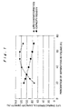
- Fig. 1 is a graph showing life test results of an alkaline rechargeable battery according to an embodiment of the present invention and of a conventional example;
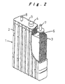
- Fig. 2 is a partially broken perspective view of an alkaline rechargeable battery; and
- Fig. 3 is a half cross-sectional perspective view of another alkaline rechargeable battery.
-
- Fig. 2 shows an arrangement of a nickel-metal hydride rechargeable battery 1, and Fig. 3 shows an arrangement of an alkaline
rechargeable battery 9 having acylindrical battery case 10. In Fig. 2, the nickel-metal hydride rechargeable battery 1 includes abattery case 2 accommodating, together with an electrolyte, an electrode plate group 3 serving as an element for electromotive force and formed by alternately stacking positive electrode plates having nickel hydroxide as its active material and negative electrode plates having hydrogen-absorption alloy with separators interposed therebetween. An opening of thebattery case 2 is closed with a lid 5 having a safety vent 4. Leads 6 are extended upward from an upper edge of each positive electrode plate on one side, and are connected to apositive electrode terminal 7. Similarly, leads 6 are extended upward from an upper edge of each negative electrode plate on the other side, and are connected to anegative electrode terminal 8. Thepositive electrode terminal 7 and thenegative electrode terminal 8 are attached to the lid 5. - In an embodiment, a foamed nickel provided with a 5-mm-wide unfilled portion at the end is filled with a positive electrode material mainly including nickel hydroxide, and a nickel lead is attached to the unfilled portion, whereby a positive electrode plate having a capacity of 1 Ah and a reaction area of 39.3 cm2 is produced. Also, a punched metal provided with a 5-mm-wide uncoated portion at the end is coated with a negative electrode material mainly including hydrogen-absorption alloy of 20 µm in average particle diameter, and a nickel lead is attached to the uncoated portion, whereby a negative electrode plate having a capacity of 1.25 Ah and a reaction area of 39.3 cm2 is produced.
- The positive electrode plate is covered with a pouchshaped separator made of a 0.18-mm-thick non-woven fabric made of polypropylene fibers having a specific gravity of 0.91. The electrode plate group 3 is formed by alternately stacking the positive electrode plates and the negative electrode plates, which is accommodated in the
battery case 2 made of synthetic resin. A connection with the external terminals is established by collecting the leads 6 and bonding their respective top portions to thepositive electrode terminal 7 and thenegative electrode terminal 8 by means of resistance welding. Thebattery case 2 is filled with 20 g of an electrolyte mainly including potassium hydroxide, and then is sealed with the lid 5, whereby a nickel-metal hydride rechargeable battery 1 is produced. The battery 1 is then charged and discharged at 0.1 C for activation. The battery 1 thus produced has a capacity of about 7 Ah. - A life test was conducted by using nickel-metal hydride rechargeable batteries produced as above. Conditions of the life test were as follows: the battery was initially charged for 5 hours at 1 A, and in the second cycle and thereafter, the battery was discharged for four hours at 1 A, and charged for four hours and four minutes at 1 A.
- Batteries were produced with separators respectively having a thickness of 0.10, 0.14, 0.18, 0.27, 0.41, 0.62, and 0.96 mm. A volume of the separators in the respective batteries accounted for 20, 25, 30, 40, 50, 60, and 70% of a volume of the electrode plate group before the initial charge and discharge. A proportion of the separators in the electrode plate group in volume was calculated based on a thickness of the separators at the cross section measured by cutting the battery before the initial charge and discharge in a direction perpendicular to the electrode plate group. Then, the life characteristics of the respective batteries were measured. The life characteristics were evaluated in terms of a percentage of a capacity, and more specifically, the expiration of the life was judged when a percentage of the battery capacity dropped to 65% or below of the initial capacity of the respective batteries, and the life characteristics were evaluated relatively on a basis of 100 with respect to those of the battery designed to have a percentage of the separators in volume of 30%. The results are set forth in Fig. 1. The capacity density of the battery is also set forth in Fig. 1.
- The results reveal that the life characteristics were deteriorated extremely when the percentage of the separators in volume was 20 or 25%. The reason why is assumed that the separators were compressed by the electrode plates expanded while the battery was charged and discharged, and were not able to retain the electrolyte. When the percentage was 70%, the volume of the separators was so large that the capacity density of the battery dropped as low as 80% or below compared with the capacity density when the percentage of the separators in volume was 30%. Also, it became difficult to release heat generated inside the battery to the outside, and the life characteristics were deteriorated compared with those when the percentage was 60%. Hence, it is understood that a preferable percentage of the separators in volume is 30 to 60%.
- Batteries were produced by setting a thickness of the separators to 0.18 mm and a percentage of the separators in the electrode plate group in volume before the initial charge and discharge to 30%, and by changing a proportion of voids to 45, 50, 60, 70, and 75%. The life test was conducted in the same manner as was in Experiment 1. Also, the output characteristics of the respective batteries were measured. Herein, after SOC in each battery was adjusted to 60%, each was discharged at a large current, and a current value at which a time required that a voltage of the battery decreased to 1 V was 10 seconds or longer was multiplied by 1 V and outputted as the output characteristics in a unit of W. Each measured value is an average of ten batteries. The test results are set forth in Table 1 below.
Proportion of Voids (%) Life Characteristics (Cycles) Output Characteristics (W) 45 1000 100 50 5000 130 60 6000 140 70 5000 150 75 Short-circuit Short-circuit - The results reveal that when the proportion of voids was 75% or higher, a short-circuit occurred during the test, which made it impossible to ensure the reliability. when the proportion of voids was 45% or lower, a volume of retained electrolyte was reduced, and what is worse, the separators were compressed by the expanded electrode plates and a quantity of the retained electrolyte was further reduced, which resulted in deterioration of the life characteristics. Consequently, it is understood that an adequate proportion of voids of the separators is 50 to 70%.
- Batteries were produced each with an electrode plate group formed by combining positive electrode plates, negative electrode plates, and separators by setting a thickness of the separators to 0.18 mm and a percentage of the separators in the electrode plate group in volume before the initial charge and discharge to 30%, and by changing a percentage of a volume of the electrode plate group in a capacity of the battery case to 83, 85, 90, 95, and 97%. The life test was conducted in the same manner as was in Experiment 1. Also, the output characteristics of the respective batteries were measured in the same manner as were in
Experiment 2. The test results are set forth in Table 2 below.Percentage of Electrode Plate Group Volume in Battery Case Capacity Life Characteristics (Cycles) Output Characteristics (W) 83 1000 80 85 5000 120 90 6000 130 95 5000 130 97 1000 130 - The results reveal that when the percentage of the volume of the electrode plate group in the capacity of the battery case was 97% or higher, the separators were compressed by the expanded electrode plates, and it became difficult for the separators to retain the electrolyte, which shortened the service life. When the percentage was 83%, the separators were not crushed after the electrode plates expanded due to charging and discharging of the battery. Thereby, an interval between the electrode plates did not reduce, so that smooth migration of electrons was not achieved. Thus, the output characteristics were deteriorated and an internal resistance was increased, whereby the life characteristics were deteriorated. Based on the foregoing, it is understood that an adequate percentage of the volume of the electrode plate group in the capacity of the battery case is 85 to 95%.
- It should be noted that the present invention is not limited to a nickel-metal hydride rechargeable battery, and can be applied to a nickel-cadmium battery as well. Also, the invention is applicable not only to a prismatic battery, but also to a cylindrical battery.
- According to the alkaline rechargeable battery of the invention, it is possible to prevent compression of the separators that shortens the life of the battery. Also, it prevents the life characteristics from being deteriorated due to difficulty of releasing heat generated inside the battery to the outside. Hence, a total quantity of electricity that the battery can be charged and discharged is increased and the life characteristics of the battery are enhanced. As a result, a battery maintaining a high reliability over a long period is provided.
Claims (3)
- An alkaline rechargeable battery comprising an electrode plate group (3) formed by superimposing a positive electrode plate and a negative electrode plate with a separator interposed therebetween; and
a battery case (2, 10) for accommodating the electrode plate group (3),
characterized in that a volume of the separators before initial charge and discharge accounts for 30 to 60% of a volume of the electrode plate group (3). - The alkaline rechargeable battery according to claim 1, wherein a proportion of voids of the separators before the initial charge and discharge is 50 to 70%.
- The alkaline rechargeable battery according to claim 1, wherein a percentage of the volume of the electrode plate group (3) before the initial charge and discharge in a capacity of the battery case (2, 10) is 85 to 95%.
Applications Claiming Priority (2)
| Application Number | Priority Date | Filing Date | Title |
|---|---|---|---|
| JP2001140964A JP4126684B2 (en) | 2001-05-11 | 2001-05-11 | Nickel metal hydride secondary battery |
| JP2001140964 | 2001-05-11 |
Publications (3)
| Publication Number | Publication Date |
|---|---|
| EP1256994A2 true EP1256994A2 (en) | 2002-11-13 |
| EP1256994A3 EP1256994A3 (en) | 2004-11-17 |
| EP1256994B1 EP1256994B1 (en) | 2006-10-11 |
Family
ID=18987482
Family Applications (1)
| Application Number | Title | Priority Date | Filing Date |
|---|---|---|---|
| EP02253305A Expired - Lifetime EP1256994B1 (en) | 2001-05-11 | 2002-05-10 | Alkaline rechargeable battery |
Country Status (5)
| Country | Link |
|---|---|
| US (1) | US6835501B2 (en) |
| EP (1) | EP1256994B1 (en) |
| JP (1) | JP4126684B2 (en) |
| CN (1) | CN1303704C (en) |
| DE (1) | DE60215253T2 (en) |
Families Citing this family (7)
| Publication number | Priority date | Publication date | Assignee | Title |
|---|---|---|---|---|
| JP4031620B2 (en) | 2001-04-09 | 2008-01-09 | 松下電器産業株式会社 | Nickel metal hydride storage battery and method of using the same |
| JP3709197B2 (en) * | 2003-08-25 | 2005-10-19 | 松下電器産業株式会社 | Cylindrical battery and manufacturing method thereof |
| CA2610266A1 (en) * | 2005-06-08 | 2006-12-14 | Powercast Corporation | Powering devices using rf energy harvesting |
| US20090102296A1 (en) * | 2007-01-05 | 2009-04-23 | Powercast Corporation | Powering cell phones and similar devices using RF energy harvesting |
| KR101084909B1 (en) * | 2009-12-07 | 2011-11-17 | 삼성에스디아이 주식회사 | Electrode assembly bluck and method for manufacturing thereof, secondary battery and method for manufacturing thereof |
| JP7232820B2 (en) | 2017-09-01 | 2023-03-03 | パワーキャスト コーポレイション | Methods, systems and apparatus for automatic RF power transfer and single antenna energy collection |
| US10763687B2 (en) | 2017-12-04 | 2020-09-01 | Powercast Corporation | Methods, systems, and apparatus for wireless recharging of battery-powered devices |
Citations (6)
| Publication number | Priority date | Publication date | Assignee | Title |
|---|---|---|---|---|
| US3377201A (en) * | 1964-03-24 | 1968-04-09 | Yardney International Corp | Spiral battery cell |
| US3716411A (en) * | 1970-02-02 | 1973-02-13 | Matsushita Electric Ind Co Ltd | Rechargeable alkaline manganese cell |
| US4190707A (en) * | 1977-10-03 | 1980-02-26 | Asahi Kasei Kogyo Kabushiki Kaisha | Alkaline battery separator |
| WO2000011732A1 (en) * | 1998-08-21 | 2000-03-02 | Eveready Battery Company, Inc. | Battery constructions having increased internal volume for active components |
| WO2000036667A2 (en) * | 1998-12-15 | 2000-06-22 | Duracell Inc. | Electrochemical cell closure |
| JP2001006748A (en) * | 1999-06-22 | 2001-01-12 | Sony Corp | Nonelectrolyte battery |
Family Cites Families (6)
| Publication number | Priority date | Publication date | Assignee | Title |
|---|---|---|---|---|
| US5318866A (en) * | 1993-04-23 | 1994-06-07 | Pall Corporation | Battery separators |
| JPH06333552A (en) | 1993-05-21 | 1994-12-02 | Japan Storage Battery Co Ltd | Nonaqueous secondary battery |
| US5492781A (en) * | 1994-01-18 | 1996-02-20 | Pall Corporation | Battery separators |
| JP3519775B2 (en) | 1994-03-16 | 2004-04-19 | 三洋電機株式会社 | Sealed nickel-hydrogen storage battery |
| DK1092243T3 (en) * | 1998-06-05 | 2003-06-30 | Dsm Nv | Process for making a microporous film |
| JP4659187B2 (en) * | 1999-09-14 | 2011-03-30 | 日本バイリーン株式会社 | Battery separator |
-
2001
- 2001-05-11 JP JP2001140964A patent/JP4126684B2/en not_active Expired - Lifetime
-
2002
- 2002-05-10 US US10/142,157 patent/US6835501B2/en not_active Expired - Lifetime
- 2002-05-10 DE DE60215253T patent/DE60215253T2/en not_active Expired - Lifetime
- 2002-05-10 EP EP02253305A patent/EP1256994B1/en not_active Expired - Lifetime
- 2002-05-10 CN CNB021189773A patent/CN1303704C/en not_active Expired - Lifetime
Patent Citations (6)
| Publication number | Priority date | Publication date | Assignee | Title |
|---|---|---|---|---|
| US3377201A (en) * | 1964-03-24 | 1968-04-09 | Yardney International Corp | Spiral battery cell |
| US3716411A (en) * | 1970-02-02 | 1973-02-13 | Matsushita Electric Ind Co Ltd | Rechargeable alkaline manganese cell |
| US4190707A (en) * | 1977-10-03 | 1980-02-26 | Asahi Kasei Kogyo Kabushiki Kaisha | Alkaline battery separator |
| WO2000011732A1 (en) * | 1998-08-21 | 2000-03-02 | Eveready Battery Company, Inc. | Battery constructions having increased internal volume for active components |
| WO2000036667A2 (en) * | 1998-12-15 | 2000-06-22 | Duracell Inc. | Electrochemical cell closure |
| JP2001006748A (en) * | 1999-06-22 | 2001-01-12 | Sony Corp | Nonelectrolyte battery |
Non-Patent Citations (1)
| Title |
|---|
| PATENT ABSTRACTS OF JAPAN vol. 2000, no. 16, 8 May 2001 (2001-05-08) -& JP 2001 006748 A (SONY CORP), 12 January 2001 (2001-01-12) * |
Also Published As
| Publication number | Publication date |
|---|---|
| JP2002343417A (en) | 2002-11-29 |
| DE60215253D1 (en) | 2006-11-23 |
| CN1303704C (en) | 2007-03-07 |
| JP4126684B2 (en) | 2008-07-30 |
| CN1385909A (en) | 2002-12-18 |
| EP1256994A3 (en) | 2004-11-17 |
| DE60215253T2 (en) | 2007-01-18 |
| EP1256994B1 (en) | 2006-10-11 |
| US6835501B2 (en) | 2004-12-28 |
| US20030003366A1 (en) | 2003-01-02 |
Similar Documents
| Publication | Publication Date | Title |
|---|---|---|
| JP3943822B2 (en) | Battery spiral electrode group and battery | |
| US7560188B2 (en) | Nickel-metal hydride rechargeable battery | |
| US6835501B2 (en) | Alkaline rechargeable battery | |
| US7435511B2 (en) | Nickel-metal hydride storage battery | |
| CN112018456A (en) | Method for manufacturing secondary battery and nickel-hydrogen secondary battery | |
| CN112117501A (en) | Method for manufacturing nickel-hydrogen secondary battery | |
| US6268083B1 (en) | Alkaline storage battery | |
| US6893771B2 (en) | Battery assembly | |
| CN110419138B (en) | Nickel-metal hydride battery and method for manufacturing same | |
| CN114300759B (en) | Method for manufacturing nickel-hydrogen storage battery | |
| CN112886075B (en) | Method for manufacturing nickel-hydrogen storage battery | |
| JPH05283071A (en) | Activation of metal hydride storage battery | |
| WO2008085001A1 (en) | Negative plate for nickel/metal hydride secondary battery and fabrication method thereof | |
| JP4235805B2 (en) | Cylindrical nickel metal hydride storage battery and battery module using the same | |
| JPH11329372A (en) | Rectangular sealed alkaline storage battery | |
| JPH09199162A (en) | Sealed alkaline storage battery | |
| JPH10149807A (en) | Assembled battery | |
| CN114975896A (en) | Method for manufacturing nickel-metal hydride storage battery | |
| CN114079058A (en) | Nickel-hydrogen storage battery and method for manufacturing nickel-hydrogen storage battery | |
| JP2856855B2 (en) | Method for manufacturing prismatic nickel-metal hydride storage battery | |
| JP2001176540A (en) | Nickel hydrogen secondary battery | |
| JPH11149938A (en) | Nickel hydrogen secondary battery | |
| JPH08339821A (en) | Metal-hydrogen alkaline storage battery | |
| JPH0642375B2 (en) | Metal-hydrogen alkaline battery | |
| JPH10162856A (en) | Nickel hydrogen square battery |
Legal Events
| Date | Code | Title | Description |
|---|---|---|---|
| PUAI | Public reference made under article 153(3) epc to a published international application that has entered the european phase |
Free format text: ORIGINAL CODE: 0009012 |
|
| AK | Designated contracting states |
Kind code of ref document: A2 Designated state(s): AT BE CH CY DE DK ES FI FR GB GR IE IT LI LU MC NL PT SE TR |
|
| AX | Request for extension of the european patent |
Free format text: AL;LT;LV;MK;RO;SI |
|
| PUAL | Search report despatched |
Free format text: ORIGINAL CODE: 0009013 |
|
| AK | Designated contracting states |
Kind code of ref document: A3 Designated state(s): AT BE CH CY DE DK ES FI FR GB GR IE IT LI LU MC NL PT SE TR |
|
| AX | Request for extension of the european patent |
Extension state: AL LT LV MK RO SI |
|
| 17P | Request for examination filed |
Effective date: 20050429 |
|
| AKX | Designation fees paid |
Designated state(s): DE FR GB |
|
| GRAP | Despatch of communication of intention to grant a patent |
Free format text: ORIGINAL CODE: EPIDOSNIGR1 |
|
| GRAS | Grant fee paid |
Free format text: ORIGINAL CODE: EPIDOSNIGR3 |
|
| GRAA | (expected) grant |
Free format text: ORIGINAL CODE: 0009210 |
|
| AK | Designated contracting states |
Kind code of ref document: B1 Designated state(s): DE FR GB |
|
| REG | Reference to a national code |
Ref country code: GB Ref legal event code: FG4D |
|
| REF | Corresponds to: |
Ref document number: 60215253 Country of ref document: DE Date of ref document: 20061123 Kind code of ref document: P |
|
| ET | Fr: translation filed | ||
| PLBE | No opposition filed within time limit |
Free format text: ORIGINAL CODE: 0009261 |
|
| STAA | Information on the status of an ep patent application or granted ep patent |
Free format text: STATUS: NO OPPOSITION FILED WITHIN TIME LIMIT |
|
| 26N | No opposition filed |
Effective date: 20070712 |
|
| REG | Reference to a national code |
Ref country code: DE Ref legal event code: R084 Ref document number: 60215253 Country of ref document: DE |
|
| REG | Reference to a national code |
Ref country code: GB Ref legal event code: 746 Effective date: 20160222 |
|
| REG | Reference to a national code |
Ref country code: FR Ref legal event code: PLFP Year of fee payment: 15 |
|
| REG | Reference to a national code |
Ref country code: FR Ref legal event code: PLFP Year of fee payment: 16 |
|
| REG | Reference to a national code |
Ref country code: FR Ref legal event code: PLFP Year of fee payment: 17 |
|
| PGFP | Annual fee paid to national office [announced via postgrant information from national office to epo] |
Ref country code: DE Payment date: 20210413 Year of fee payment: 20 Ref country code: FR Payment date: 20210412 Year of fee payment: 20 |
|
| PGFP | Annual fee paid to national office [announced via postgrant information from national office to epo] |
Ref country code: GB Payment date: 20210414 Year of fee payment: 20 |
|
| REG | Reference to a national code |
Ref country code: DE Ref legal event code: R071 Ref document number: 60215253 Country of ref document: DE |
|
| REG | Reference to a national code |
Ref country code: GB Ref legal event code: PE20 Expiry date: 20220509 |
|
| PG25 | Lapsed in a contracting state [announced via postgrant information from national office to epo] |
Ref country code: GB Free format text: LAPSE BECAUSE OF EXPIRATION OF PROTECTION Effective date: 20220509 |