EP1256786A2 - Split-flow flowmeter - Google Patents
Split-flow flowmeter Download PDFInfo
- Publication number
- EP1256786A2 EP1256786A2 EP02253193A EP02253193A EP1256786A2 EP 1256786 A2 EP1256786 A2 EP 1256786A2 EP 02253193 A EP02253193 A EP 02253193A EP 02253193 A EP02253193 A EP 02253193A EP 1256786 A2 EP1256786 A2 EP 1256786A2
- Authority
- EP
- European Patent Office
- Prior art keywords
- flow
- split
- protrusion
- detection element
- flowmeter according
- Prior art date
- Legal status (The legal status is an assumption and is not a legal conclusion. Google has not performed a legal analysis and makes no representation as to the accuracy of the status listed.)
- Withdrawn
Links
Images



Classifications
-
- G—PHYSICS
- G01—MEASURING; TESTING
- G01F—MEASURING VOLUME, VOLUME FLOW, MASS FLOW OR LIQUID LEVEL; METERING BY VOLUME
- G01F1/00—Measuring the volume flow or mass flow of fluid or fluent solid material wherein the fluid passes through a meter in a continuous flow
- G01F1/72—Devices for measuring pulsing fluid flows
-
- G—PHYSICS
- G01—MEASURING; TESTING
- G01F—MEASURING VOLUME, VOLUME FLOW, MASS FLOW OR LIQUID LEVEL; METERING BY VOLUME
- G01F5/00—Measuring a proportion of the volume flow
-
- G—PHYSICS
- G01—MEASURING; TESTING
- G01F—MEASURING VOLUME, VOLUME FLOW, MASS FLOW OR LIQUID LEVEL; METERING BY VOLUME
- G01F1/00—Measuring the volume flow or mass flow of fluid or fluent solid material wherein the fluid passes through a meter in a continuous flow
- G01F1/68—Measuring the volume flow or mass flow of fluid or fluent solid material wherein the fluid passes through a meter in a continuous flow by using thermal effects
- G01F1/684—Structural arrangements; Mounting of elements, e.g. in relation to fluid flow
- G01F1/6842—Structural arrangements; Mounting of elements, e.g. in relation to fluid flow with means for influencing the fluid flow
Definitions
- the present invention relates to a split-flow flowmeter for measuring parameters related to flow, particularly flow rate and flow velocity. More particularly, the invention relates to a split-flow flowmeter using an exothermic or endothermic detection element and/or a detection element integrally formed on a semiconductor chip; for example, a split-flow flowmeter favorably applicable to a mass flow sensor for use in combustion control of a vehicle engine or an industrial engine, a mass flow sensor for use in an industrial air-conditioning system or a compressed-air supply system, or a flow sensor for use in control of the air-fuel ratio of a household gas cooker.
- split-flow flowmeter has been proposed as a flowmeter for measuring a flow rate within a suction pipe.
- the split-flow flowmeter detects a portion of flow diverted from a main-flow pipe (an object pipe of measurement) into a flow path thereof (hereinafter also referred to as a "split-flow passage" or a “flow splitter tube”) to thereby measure a flow rate in the main-flow pipe.
- a conventionally proposed split-flow flowmeter involves the following problems: flow disturbance on a detection element is great; in particular, the measurement accuracy is low in measuring a low-flow-rate region.
- the present invention provides a flowmeter for detecting a portion of flow diverted from a main-flow pipe, which is an object of measurement, into the same, using a detection element so as to measure parameters related to the flow within the main-flow pipe; i.e., a split-flow flowmeter, which comprises a detection element disposed to face a flow path through which a fluid to be measured flows, and a venturi structure adapted to throttle a flow directed toward the detection element to thereby reduce disturbance of the flow.
- the split-flow flowmeter is characterized in that the venturi structure is disposed opposite the detection element within the flow path and comprises a protrusion protruding toward the detection element within the flow path.
- This split-flow flowmeter is mainly characterized in that a portion of the venturi structure assumes the form of a protrusion. However, the entire venturi structure (the venturi structure itself) may assume the form of a protrusion.
- the venturi structure reduces flow disturbance in the vicinity of the detection element within the flow path of the split-flow flowmeter, whereby a flow rate can be accurately measured with small variations in output.
- the protrusion reduces a region where resistance to flow arises, and can generate a large pressure difference, whereby the rate of flow passing through a clearance between the protrusion and the detection element can be easily increased even in measuring a low-flow-rate region, thereby greatly enhancing output.
- a venturi structure partially protrudes (a protrusion is formed on the venturi structure); i.e., a portion of the venturi structure is formed into a protrusion.
- the protrusion is disposed opposite a detection element within a flow path of a split-flow-type flowmeter and protrudes toward the detection element within the flow path.
- An example of the detection element may be a diaphragm type in which a heater and two temperature sensors are formed for detecting a gas flow (as can be referred in a US Patent Application No. 09/754,343 or European Patent Application No. 01300077.3 filed by the present applicant).
- the venturi structure is configured such that the outside wall of a bottom portion of a curved partition, which is disposed within a split-flow passage so as to impart substantially the shape of the letter ⁇ to the passage, is disposed opposing the detection element in the proximity thereof.
- a protrusion is formed which protrudes toward the detection element from the outside wall of the curved partition.
- a height (B) of the protrusion is preferably in the range of 0.5 - 4.5 mm, a gap or clearance (A) between the protrusion and the detection element is preferably in the range of 0.3-3 mm and a thickness (Dt) of the protrusion is preferably in the range of 0.5- 3 mm not exceeding the width or length of the detection element as measured in a gas flow direction, as may be understood by Fig. 9. It is more preferable that the protrusion has a ridge-like shape as shown in Fig. 11, in which a ridge length (H) is preferably in the rage of 1-10 mm and the length of the detection element is within the ridge length (H).
- a convex radius (C) formed at a bottom skirt of the protrusion as shown in Fig.9 is about less than 2 mm.
- a portion or the entirety of a surface of the protrusion which faces the detection element is curved. This feature prevents the generation of vortexes or separation of flow in the vicinity of the protrusion, and thus disturbance of air flow is reduced, thereby enhancing output.
- a section of the protrusion taken along a plane extending in a flow direction in a flow path (split-flow passage) of a split-flow flowmeter assumes, singly or in combination, any of a triangular shape, a rectangular shape, a polygonal shape, a spindle shape, a semicircular shape, and a semi-elliptic shape.
- This feature can greatly reduce a region where resistance to flow arises, thereby enhancing output in measurement not only in a low-flow-rate region but also in a high-flow-rate region.
- the venturi structure comprises a plurality of protrusions.
- Employing a plurality of protrusions in combination can impart the desired flow rate characteristics to the flowmeter.
- the flow path structure of the split-flow flowmeter is formed to have symmetry with respect to a plane including the centerline perpendicular to a detection portion of the detection element.
- the plurality of protrusions are arranged symmetrically with respect to the plane.
- Such a split-flow-type flowmeter can equivalently measure a regular flow and a backflow.
- the plurality of protrusions are formed or arranged opposite one another along the flow transversal direction of the flow path of the split-flow flowmeter.
- a groove or a space is formed between the protrusions and functions to guide a flow toward the detection portion of the detection element.
- a groove or a space which opens toward the detection portion of the detection element is formed between the plurality of protrusions.
- This feature allows sufficient flow rate in measuring a low-flow-rate region, and thus output is enhanced in measuring a low-flow-rate region. Since a throttle is formed in a very small region, a flow can only be led to the detection portion of the detection element while a region where resistance to flow arises is reduced. Additionally, since a large pressure difference can be generated, flow rate can be increased in measuring a low-flow-rate region, thereby enhancing output.
- a high protrusion which protrudes toward the detection element is formed between the plurality of protrusions.
- throttling effected by the central high protrusion enhances output.
- low protrusions located on either side of the central high protrusion provide bypasses in order to delay saturation to thereby increase output during measurement of high flow rate.
- the clearance between the tip of the protrusion and the detection element is equal to or smaller than the length of the protrusion as measured along a direction parallel with the surface of the diaphragm of the detection element and perpendicular to a flow direction (a length as measured along the flow transversal direction).
- the clearance between a tip-top of the protrusion and the detection element is preferably not greater than 3 mm.
- a split-flow-type flowmeter according to the present invention can measure not only flow rate but also parameters related to flow, such as flow velocity, as needed.
- the preferred mode for carrying out the present invention comprises a bypass flow path straightly connecting the flow inlet and the flow outlet and bypassing the split-flow passage and/or a venturi structure for decreasing the diameter of the split-flow passage in the vicinity of the detection element.
- the bypass flow path stabilizes supply of fluid to be measured to the detection element and facilitates diversion of fluid to be measured (flow in the main-flow pipe) into the split-flow passage.
- the venturi structure effectively rectifies turbulence of fluid to be measured which would otherwise arise on a detection portion (also referred to as a detection surface) of the detection element.
- the split-flow passage assumes a symmetrical structure such that the inlet side and the outlet side are symmetrical with respect to the detection element
- employing a venturi structure for decreasing the size of the bypass flow path or the diameter of a flow cross section of the bypass flow path further stabilizes flow reaching the detection element even when pulsation or pulsation plus backflow is generated.
- a venturi structure is disposed in the bypass flow path to thereby determine the flow rate of fluid to be measured and diverted toward the detection element, by means of the amount of projection of a flow path wall which constitutes the venturi structure or the area of opening of the venturi structure.
- the flow rate of flow heading for the detection element can be quantitatively controlled.
- flow control means for forming flow hitting obliquely on the detection surface of the detection element is provided in the split-flow passage.
- the flow control means causes steady flow onto the detection surface of the detection element, so that flow to be detected reliably flows on the detection surface. Additionally, since generation of vortexes and separation of flow in the vicinity of the detection surface is suppressed, detection accuracy and reproducibility are enhanced.
- flow control means for forming flow hitting obliquely on the detection surface of the detection element or forming flow flowing obliquely with respect to the detection surface assumes the form of a flow path surface (an elevated portion) elevated above the detection surface, which elevated flow path is located at least upstream of the detection element, or upstream and/or downstream of the detection element.
- the form of elevation is not particularly limited so long as a flow hitting obliquely on the detection surface is formed.
- the form of elevation is concave or convex, or the elevated surface is a linear, polygonal, or concavely-curved slant surface.
- the detection surface of the detection element is exposed to the interior of the split-flow passage (detection tube) at an inflection portion of the split-flow passage.
- an inflection tube split-flow passage
- the detection element is disposed at an inflection portion (a bent portion, or a curved portion of flow path) of the inflection tube.
- the detection element is disposed at or in the vicinity of a portion of the split-flow passage where flow is inverted or the direction of flow is greatly changed.
- the detection surface of the detection element is exposed to a portion of the interior of the split-flow passage where flow is fast.
- the detection surface of the detection element is exposed to a portion, or its vicinity, of the interior of the split-flow passage where flow is throttled and then changes its direction.
- the detection element mounted on the bottom wall of the split-flow passage (a wall of the flow path located farthest away from the flow inlet and the flow outlet) is located outside the main-flow pipe.
- the detection element can be readily mounted or replaced.
- output from the detection element is readily released.
- the detection element is a thermal detection element comprising a substrate and four thin-film resistors formed on the substrate. More specifically, a diaphragm section and a rim section are formed on a semiconductor substrate.
- the diaphragm section includes (1) an upstream temperature sensor, (2) a downstream temperature sensor, and (3) a heater disposed between the upstream temperature sensor and the downstream temperature sensor.
- the rim section includes (4) an ambient temperature sensor. The diaphragm section is finished very thinly and is thermally insulated.
- the detection element is a thermal detection element comprising a substrate and three thin-film resistors formed on the surface of the substrate. More specifically, a diaphragm section and a rim section are formed on a semiconductor substrate.
- the diaphragm section includes (1) an upstream heater and (2) a downstream heater.
- the rim section includes (3) an ambient temperature sensor.
- the diaphragm section is finished very thin and thermally insulated.
- the detection element measures flow-related values, such as flow rate and/or flow velocity, on the basis of temperature.
- the split-flow-type flowmeter according to the present invention can be installed in an intake system of an engine to be mounted in various kinds of vehicles, two-wheeled and four-wheeled, in order to measure an intake rate or a like parameter.
- the split-flow-type flowmeter according to the present invention is installed in an intake system of an engine to be mounted in a four-wheeled vehicle, somewhere on a pipe line extending between the interior of an air cleaner and a throttle valve.
- the split-flow-type flowmeter according to the present invention is installed in an intake system of an engine to be mounted on a two-wheeled vehicle; specifically, on an intake pipe connected to a cylinder, on an air funnel within an air cleaner box, or on a like location, in order to measure an intake gas flow rate, an intake gas flow velocity, or a like parameter.
- split-flow-type flowmeter specifically, a split-flow-type flowmeter including a venturi structure disposed in opposition to a detection element and configured in such a manner as to partially protrude, will be described.
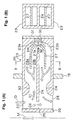
- Figs. 1(A) and 1(B) are views for explaining the structure of the split-flow-type flowmeter according to the present embodiment.
- Fig. 1(A) is a longitudinal, central sectional view of the split-flow-type flowmeter taken along a plane extending along the axial direction of a main-flow pipe, which is an object of measurement.
- Fig. 1(B) is a sectional view taken along line B-B in Fig. 1(A).
- a main flow M which is an object flow of measurement, flows through a main-flow pipe 19.
- a flow splitter tube 20 is attached to the main-flow pipe 19 perpendicularly to the axial direction of the main-flow pipe 19 so as to divert a split flow D from a main flow M into the same.
- a split-flow passage is formed in the flow splitter tube 20 in such a manner as to be curved substantially in the shape of the letter ⁇ by an approach plate 24 (main separator) extending substantially perpendicularly to the direction of the main flow M (the axial direction of the main-flow pipe 19).
- a flow inlet (which may serve as a flow outlet) 25 and a flow outlet (which may serve as a flow inlet) 26 are formed on an outer wall 23 of the flow splitter tube 20 at opposite positions so as to face each other while opening on respective planes extending substantially perpendicularly to the direction of the main flow M.
- a bypass flow path is formed between a top wall 29 of the flow splitter tube 20 and one end of the approach plate 24 and provides a shortcut between the flow inlet 25 and the flow outlet 26.
- a partition 27 is formed within the flow splitter tube 20 in such a manner as to be curved according to a curved profile of the interior of the flow splitter tube 20.
- the partition 27 forms an outer split-flow passage 28a and an inner split-flow passage 28b within the flow splitter tube 20 such that a flow path branches into the inner and outer split-flow passages 28a and 28b, which, in turn, merge together to become a flow path.
- Undulations 33 and 34 are formed on the inner surface of the outer wall 23 at opposite positions (in the vicinity of the flow inlet 25 and the flow outlet 26, respectively) and rise in such a direction as to block the inlet and outlet of the outer split-flow passage 28a.
- the undulations 33 and 34 provide throttling in the flow path extending between the flow inlet 25 and the inlet of the outer split-flow passage 28a and in the flow path extending between the flow outlet 26 and the outlet of the outer split-flow passage 28a.
- a detection element 32 is attached to a bottom wall of the flow splitter tube 20 via a circuit board 31 in such a manner as to be exposed to flow within the outer split-flow passage 28a. In this manner, the detection element 32 is disposed at an inflection portion of the flow splitter tube 20 and is located outside the main-flow pipe 19 for easy replacement.
- a venturi structure 30 is formed between the detection element 32 and the partition 27.
- the venturi structure 30 throttles a flow flowing toward the detection element 32 so as to reduce disturbance of the flow.
- venturi structure 30 includes a protrusion 30a, which protrudes toward a detection surface of the detection element 32.
- Elevated portions 23a and 23b are formed on the inner surface of a bottom portion of the outer wall 23 on either side of the detection element 32 in such a manner as to rise toward the center of a flow cross section of the outer split-flow passage 28a.
- a flow path surface on the elevated portions 23a and 23b is formed into a concave surface.
- the partition 27 is convexly curved toward the detection element 32 in the vicinity of the detection element 32.
- a flow path surface of a detection-element facing portion 27a of the partition 27 is formed into a convex surface, which is convexed toward the detection element 32.
- Such a flow path structure causes formation of a downflow DW, which obliquely flows toward the detection surface of the detection element 32.
- the flow splitter tube 20 has a flow path structure which exhibits symmetry with respect to the detection element 32 and with respect to a predetermined plane including the centerline perpendicular to the detection surface of the detection element 32.
- the flow splitter tube 20 can be used to measure the flow rate of the main flow M similarly between the case where the main flow M flows from left to right in Fig. 1(A) (regular flow) and the case where the main flow M flows from right to left in Fig. 1(A) (reverse flow).
- the venturi structure provided in the vicinity of the detection element includes a protrusion protruding toward the detection element, or the venturi structure itself assumes the form of a protrusion.
- the above description can be referred to as appropriate.
- the description below mainly discusses the differences between the above-described split-flow-type flowmeter and split-flow-type flowmeters according to Embodiments 2 to 6 to be described below.
- Fig. 2 is a view for explaining variations in the structure of a protrusion formed on the venturi structure in the split-flow-type flowmeter according to Embodiment 1 of the present invention or a like flowmeter.
- Fig. 2 shows a matrix of partial sectional views of respective split-flow-type flowmeters. The sections are taken along the same direction as in the case of the section of Fig. 1(A). The partition (main separator) is omitted in Fig. 2.
- Column (1) shows a type in which a venturi structure does not include a protrusion (the entire venturi structure (the venturi structure itself) assumes the form of a protrusion 4 (5)).
- Columns (2) to (4) show types in which a venturi structure includes a protrusion: column (2) shows a type in which the length of the protrusion 5 as measured along the flow direction is relatively long, and the width of the protrusion 5 is similar to or wider than that of a detection element 2; column (3) shows a type in which the length of the protrusion 5 as measured along the flow length is short as compared with the type of column (2), and the width of the protrusion 5 is narrower than that of the detection element 2; and column (4) shows a type in which the projecting length (height) of the protrusion 5 is longer than those of the types of columns (2) and (3).
- Row (A) shows a type in which the tip of the protrusion 5 is formed into a flat portion
- row (B) shows a type in which the tip flat portion of the protrusion 5 in column (A) is curved (radiused)
- row (C) shows a type in which the entire protrusion 5 is curved (radiused)
- row (D) shows a type in which the protrusion 5 is formed into a spindle shape
- row (E) shows a type in which the protrusion 5 is formed into an ogival form
- row (F) shows a type in which the protrusion 5 is formed into a pyramidal shape.
- the present invention can use various shapes obtained through combination of the above-described types in rows (2) to (4) and those in columns (A) to (F).
- a particularly preferred shape is of the type in row (4) column (C). This type will be described below by way of example.
- a partition 3 is provided within a flow splitter tube.
- a substantially U-shaped flow path (split-flow passage) 1 is formed in the vicinity of the detection element 2.
- a flow to be measured (split flow D (see Fig. 1(A)) is introduced into the flow path 1.
- the introduced flow flows toward the detection element 2, which is disposed in such a manner as to face the flow path 1.
- a venturi structure 4 is formed in the vicinity of the detection element 2; specifically, between the detection element 2 and the partition 3. The venturi structure 4 throttles a flow directed to the detection element 2 to thereby reduce disturbance of the flow.
- the protrusion 5 is formed on the venturi structure 4.
- the protrusion 5 protrudes toward the detection element 2 and is formed on the partition 3 such that the tip thereof faces the detection element 2 within the flow path 1.
- the tip face of the protrusion 5; i.e., the face (top face) of the protrusion 5 is curved.
- the clearance W (see column (2) row (B)) between the tip of the protrusion 5 and the detection element 2 is not greater than 3 mm.
- the protrusion 5 exhibits symmetry with respect to a plane including the centerline of the detection surface of the detection element 2. This symmetry allows a regular flow and a reverse flow to be detected in a similar manner.
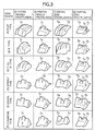
- Fig. 3 is a view for explaining variations in the structure of a protrusion formed on the venturi structure in the split-flow-type flowmeter according to Embodiment 1 of the present invention.
- Fig. 3 shows a matrix of partial perspective views of partitions of respective split-flow-type flowmeters.
- the venturi structure includes a single or a plurality of small protrusions (small protrusions).
- small protrusions small protrusions
- a flow to be detected basically flows from upper right to lower left (or in the reverse direction).
- Column (5) shows a type in which a central portion of a partition as observed on the flow cross section of a flow path entirely protrudes (a middle protrusion 7c is included); column (6) shows a type in which a central portion of a protrusion as observed along the flow direction protrudes (the middle protrusion 7c is included); column (7) shows a type in which opposite end portions of a partition as observed on the flow cross section of a flow path entirely protrude (end protrusions 7a and 7b are included); and column (8) shows a type in which opposite end portions of a protrusion protrude (the middle protrusion 7c and the end protrusions 7a and 7b are included). Types shown in rows (A) to (F) are similar to those of Embodiment 1 described previously, and therefore their redundant description is omitted.
- the present invention can use various shapes obtained through combination of the above-described types in rows (5) to (8) and those in columns (A) to (F).
- a particularly preferred shape is of the type in row (8) column (B) and row (8) column (C). These types will be described below by way of example.
- a portion of the venturi structure includes the meddle protrusion 7c, which extends substantially in parallel with the detection surface of the detection element, and the end protrusions 7a and 7b, which are located on either side of the meddle protrusion 7c and protrude toward the detection element.
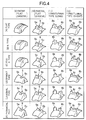
- Fig. 4 is a view for explaining variations in the structure of a protrusion formed on the venturi structure in the split-flow-type flowmeter according to Embodiment 1 of the present invention.
- Fig. 4 shows a matrix of partial perspective views of partitions of respective split-flow-type flowmeters.
- a flow to be detected basically flows from upper right to lower left (or in the reverse direction).
- Column (9) shows a type in which a flat groove 6 extending along the flow direction is formed on a central portion of a partition wall of the venturi structure;
- column (10) shows a type in which the flat groove 6 extending along the flow direction is formed between protrusions 5a and 5b formed on a portion of the venturi structure;
- column (11) shows a type in which a pair of longitudinally long protrusions 8a and 8b are provided in opposition to each other so as to effect the venturi action in two directions; i.e., a large longitudinal throttling mechanism and a small lateral throttling mechanism are formed;
- column (12) shows a type in which a pair of longitudinally long protrusions are provided in opposition to each other, and a relatively short protrusion 8c (a groove with a raised bottom) is provided between the long protrusions; i.e., a large longitudinal throttling mechanism, a small lateral throttling mechanism, and a small longitudinal lateral throttling
- the present invention can use various shapes obtained through combination of the above-described types in rows (9) to (12) and those in columns (A) to (F) as well as through additional combination with the shapes shown in Fig. 3.
- the above-described types in columns (8) and (12) may be combined such that a resultant protrusion assumes a smooth outline, whereby a venturi structure as shown in Fig. 6, which will be described later, can be obtained.
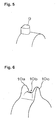
- Fig. 5 is a view for explaining a further variation of the structure of a protrusion formed on the venturi structure in the split-flow-type flowmeter according to Embodiment 1 of the present invention or a like flowmeter.
- Fig. 5 is a partial perspective view of a partition for explaining a venturi structure including only a single protrusion.
- Fig. 5 shows an example in which only a single protrusion 9 assuming a shape similar to that of the type in column (11) row (C) of Fig. 4 is formed.
- the protrusion 9 assumes a three-dimensional shape whose cross section is semielliptic as viewed from a detection element.
- the curved surface of the protrusion 9 faces toward the center of a flow path.
- Fig. 6 is a view for explaining a further variation of the structure of a protrusion formed on the venturi structure in the split-flow-type flowmeter according to Embodiment 1 of the present invention or a like flowmeter.
- Fig. 6 is a partial external view for explaining the three-dimensional shape of a protrusion including smooth curved surfaces (a partial view showing a protrusion and its vicinity).
- a saddle-shaped protrusion is formed on an arcuately or elliptically curved surface and includes three protrusions 10a, 10b, and 10c arranged in a row.
- the opposite end protrusions 10a and 10b are higher than the central protrusion 10c. Since the shape of the saddle-shaped protrusion is composed of smoothly curved surfaces, disturbance of a fluid to be measured is very low, and resistance to flow is low.
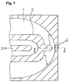
- FIG. 7 is a partial sectional view for explaining the structure and dimensions of the split-flow-type flowmeter which was used in the present Measurement Example.
- a portion of a venturi structure 4 is formed into a protrusion 5.
- the tip of the protrusion is formed into a semicircular shape (R 0.5 mm).
- the width of the protrusion 5 is about 1 mm, which is narrower than the width of a detection element (the width of a diaphragm serving as a detection portion of the detection element 2 as measured along the direction parallel with the surface of the diaphragm and perpendicular to the flow direction (a width as measured along the flow transversal direction), or 3 mm.
- the protrusion 5 has a protruding length of about 2 mm.
- the clearance between the tip of the protrusion 5 and the detection element 2 is about 0.5 mm.
- the linear flow path of the split-flow-type flowmeter has an width of opening of about 3 mm.
- An inflection portion of the flow path of the split-flow-type flowmeter has a radius of curvature of 3 mm, or R 3 mm, as measured on the inner surface thereof, and a radius of curvature of 4 mm, or R 4 mm, as measured on the outer surface thereof.
- a rising portion of the protrusion 5 has a radius of curvature of 0.5 mm, or R 0.5 mm.
- This split-flow-type flowmeter was attached to the main-flow pipe 19 as shown in Fig. 1(A), and measurement was carried out. For comparison, measurement was carried out similarly by use of a split-flow-type flowmeter according to a Comparative Example which has a structure and dimensions similar to those of the split-flow-type flowmeter according to the Example of the present invention except that the protrusion 5 shown in Fig. 7 is not provided.
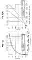
- Figs. 8(A) and 8(B) are graphs for explaining the results of Measurement Example 1.
- Fig. 8(A) is a graph showing the relationship between the flow rate in the main-flow pipe and the output of the split-flow-type flowmeters.
- Fig. 8(B) is an enlarged graph showing a portion of the graph of Fig. 8(A) which corresponds to the low-flow-rate region.
- all data appearing in Figs. 8(A) and 8(B) are represented by relative values in relation to the maximum flow rate and the maximum output which are normalized to a value of 1.0.
- the split-flow-type flowmeter according to the Example of the present invention exhibited an output level which is about 1.5-2 times that of the split-flow-type flowmeter according to the Comparative Example.
- a radius (C) When a radius (C) is less than 2 mm, the performance of flow detection is stable and not varied badly, however if it is more than 2 mm the protrusion effect is lost.
- the thickness (Dt) of the protrusion should not exceed 3 mm, or rather not exceed the width or length of the detection element as measured in the flow direction, because a sensitivity to variation of the flow pressure detected by the split flow meter is badly reduced. However the thickness (Dt) should not be less than 0.5 mm because performance matching in production becomes critical or difficult.
- E) in Fig.9 refers to a view of the protrusion 5, as shown either in Fig. 11 or Fig.12.
- (F) in Fig. 9 represents a radius of the curve formed in the elevated portion 23a or 23b of Fig.1(A), and the radius is preferably about 2-8 mm, more preferably about 3-4 mm.
- the protrusion has a straight and rounded ridge formed on a top of the protrusion.
- the clearance (A) should be less than a ridge length (H) of the rounded ridge of the protrusion as shown in Fig. 10, so that a stable and accurate flow measurement is attained.
- the ridge length H is preferably 1-10 mm, more preferably 3-6 mm, as measured perpendicular to the flow direction.
- a recessed ridged portion may be formed in the middle of the ridge of the protrusion of Fig.11.
- the ridge length (G) of the recessed ridged portion 6 (of Fig.12) as measured perpendicular to the flow direction is preferably from 0.5 mm up to the length or width (h) of the detection element 2 (of Fig.10), more preferably about 1 mm.
- the split-flow flowmeter using this ridge-recessed protrusion (as shown in Fig.12 or Fig.4) performs better than the split-flow flowmeter using the protrusion (shown in Fig 10), although adjustment of the ridge-recessed portion so as to be matched with the detection element becomes more difficult.
- the protrusion shape as shown in Fig.11 would be the best.
- the split-flow-type flowmeter according to the Example of the present invention exhibits delay in saturation of the detection curve as compared with the split-flow-type flowmeter according to the Comparative Example and thus demonstrates high resolution.
- the present invention provides a split-flow-type flowmeter capable of reducing a flow disturbance in the vicinity of a detection element within a flow path thereof and capable of accurately measuring a flow rate even in measurement in the low-flow-rate region.
Landscapes
- Physics & Mathematics (AREA)
- Fluid Mechanics (AREA)
- General Physics & Mathematics (AREA)
- Measuring Volume Flow (AREA)
Abstract
Description
Claims (12)
- A split-flow flowmeter comprising a detection element disposed to face a flow path through which a fluid to be measured flows in use, and a venturi structure adapted to throttle a flow directed toward the detection element, wherein
the venturi structure is disposed opposite the detection element within the flow path and comprises a protrusion protruding toward the detection element within the flow path. - A split-flow flowmeter according to claim 1, wherein a portion or the entirety of the surface of the protrusion which faces the detection element is curved.
- A split-flow flowmeter according to claim 1 or 2, wherein a section of the protrusion taken along a plane extending in a flow direction in the flow path assumes, singly or in combination, any of a triangular shape, a rectangular shape, a polygonal shape, a spindle shape, a semicircular shape, and a semi-elliptic shape.
- A split-flow flowmeter according to claim 1, 2 or 3, wherein the venturi structure comprises a plurality of protrusions.
- A split-flow flowmeter according to claim 4, wherein the plurality of protrusions are arranged symmetrically with respect to a predetermined plane including a centerline perpendicular to a detection portion of the detection element.
- A split-flow flowmeter according to claim 4 or 5, wherein the plurality of protrusions are arranged opposite one another along a transverse flow direction of the flow path.
- A split-flow flowmeter according to claim 4, 5 or 6, comprising a groove or a space which opens toward the detection element formed between the plurality of protrusions.
- A split-flow flowmeter according to claim 4, 5 , 6 or 7, comprising another protrusion, which protrudes toward the detection element, formed between the plurality of protrusions.
- A split-flow flowmeter according to any one of the preceding claims, wherein a clearance between the tip of the protrusion and the detection element is equal to or smaller than the length of the protrusion as measured along a direction parallel with the surface of the diaphragm of the detection element and perpendicular to a flow direction.
- A split-flow flowmeter according to claim 9, wherein the clearance is in the range of 0.3-3 mm.
- A split-flow flowmeter according to any one of the preceding claims, wherein the height of the protrusion is in the range of 0.5-4.5 mm.
- A split-flow flowmeter according to any one of the preceding claims, wherein a width of the protrusion as measured in a flow direction is in the range of 0.5-3 mm.
Applications Claiming Priority (2)
| Application Number | Priority Date | Filing Date | Title |
|---|---|---|---|
| JP2001137505A JP2002333347A (en) | 2001-05-08 | 2001-05-08 | Split flow meter |
| JP2001137505 | 2001-05-08 |
Publications (2)
| Publication Number | Publication Date |
|---|---|
| EP1256786A2 true EP1256786A2 (en) | 2002-11-13 |
| EP1256786A3 EP1256786A3 (en) | 2007-03-14 |
Family
ID=18984601
Family Applications (1)
| Application Number | Title | Priority Date | Filing Date |
|---|---|---|---|
| EP02253193A Withdrawn EP1256786A3 (en) | 2001-05-08 | 2002-05-08 | Split-flow flowmeter |
Country Status (4)
| Country | Link |
|---|---|
| US (1) | US6647776B2 (en) |
| EP (1) | EP1256786A3 (en) |
| JP (1) | JP2002333347A (en) |
| KR (1) | KR20020085838A (en) |
Cited By (4)
| Publication number | Priority date | Publication date | Assignee | Title |
|---|---|---|---|---|
| EP1443314A3 (en) * | 2002-12-23 | 2005-06-01 | Sensirion AG | Method and device to measure the flow of gas or liquid in a bypass |
| EP1754959A4 (en) * | 2004-06-10 | 2007-06-20 | Yamatake Corp | FLOW |
| EP2455724A1 (en) | 2010-11-18 | 2012-05-23 | Axetris AG | Flow sensor |
| EP2725328A1 (en) * | 2013-03-18 | 2014-04-30 | Sensirion AG | Apparatus for measuring the flow of a fluid |
Families Citing this family (29)
| Publication number | Priority date | Publication date | Assignee | Title |
|---|---|---|---|---|
| JP2005140753A (en) * | 2003-11-10 | 2005-06-02 | Mitsubishi Electric Corp | Intake air amount measuring device for internal combustion engine |
| JP4534526B2 (en) * | 2004-02-27 | 2010-09-01 | オムロン株式会社 | Flow velocity measuring device |
| JP4957081B2 (en) * | 2005-09-15 | 2012-06-20 | 株式会社デンソー | Flow measuring device |
| JP4161077B2 (en) * | 2005-09-29 | 2008-10-08 | 三菱電機株式会社 | Flow measuring device |
| JP2007121036A (en) * | 2005-10-26 | 2007-05-17 | Yamatake Corp | Flowmeter |
| DE102005056706A1 (en) * | 2005-11-28 | 2007-05-31 | BSH Bosch und Siemens Hausgeräte GmbH | Apparatus and method for monitoring airflow in a household appliance |
| US7665375B2 (en) * | 2006-12-21 | 2010-02-23 | Horiba, Ltd. | Flow splitter for a solid particle counting system |
| US7651263B2 (en) * | 2007-03-01 | 2010-01-26 | Advanced Energy Industries, Inc. | Method and apparatus for measuring the temperature of a gas in a mass flow controller |
| JP4488030B2 (en) * | 2007-06-14 | 2010-06-23 | 株式会社デンソー | Air flow measurement device |
| JP4488031B2 (en) * | 2007-06-14 | 2010-06-23 | 株式会社デンソー | Air flow measurement device |
| JP4412357B2 (en) * | 2007-06-14 | 2010-02-10 | 株式会社デンソー | Air flow measurement device |
| US7826986B2 (en) * | 2008-09-26 | 2010-11-02 | Advanced Energy Industries, Inc. | Method and system for operating a mass flow controller |
| US8656772B2 (en) | 2010-03-22 | 2014-02-25 | Honeywell International Inc. | Flow sensor with pressure output signal |
| US8511180B2 (en) | 2010-09-02 | 2013-08-20 | Ofer Melamed | Pressure difference flowmeter with flow barrier between a conduit and a reference tube |
| JP5542614B2 (en) * | 2010-10-27 | 2014-07-09 | 日立オートモティブシステムズ株式会社 | Flow measuring device |
| US8695417B2 (en) * | 2011-01-31 | 2014-04-15 | Honeywell International Inc. | Flow sensor with enhanced flow range capability |
| JP5799682B2 (en) * | 2011-09-05 | 2015-10-28 | 株式会社デンソー | Air flow measurement device |
| JP5758850B2 (en) | 2012-06-15 | 2015-08-05 | 日立オートモティブシステムズ株式会社 | Thermal flow meter |
| US9052217B2 (en) | 2012-11-09 | 2015-06-09 | Honeywell International Inc. | Variable scale sensor |
| US9176089B2 (en) | 2013-03-29 | 2015-11-03 | Stmicroelectronics Pte Ltd. | Integrated multi-sensor module |
| US9618653B2 (en) * | 2013-03-29 | 2017-04-11 | Stmicroelectronics Pte Ltd. | Microelectronic environmental sensing module |
| JP6065734B2 (en) * | 2013-04-26 | 2017-01-25 | 株式会社デンソー | Flow measuring device |
| US9000542B2 (en) | 2013-05-31 | 2015-04-07 | Stmicroelectronics Pte Ltd. | Suspended membrane device |
| DE102013223372B4 (en) * | 2013-11-15 | 2026-05-13 | GS Elektromedizinische Geräte G. Stemple GmbH | DEVICE FOR DETERMINING A FLOW PARAMETER OF A FLUID STREAM |
| CN104964721B (en) * | 2015-06-30 | 2017-12-05 | 蔡丰勇 | The gas flow structure of mass air flow sensor |
| US10254261B2 (en) | 2016-07-18 | 2019-04-09 | Stmicroelectronics Pte Ltd | Integrated air quality sensor that detects multiple gas species |
| US10429330B2 (en) | 2016-07-18 | 2019-10-01 | Stmicroelectronics Pte Ltd | Gas analyzer that detects gases, humidity, and temperature |
| US10557812B2 (en) | 2016-12-01 | 2020-02-11 | Stmicroelectronics Pte Ltd | Gas sensors |
| CN107796452B (en) * | 2017-11-16 | 2024-07-26 | 矽翔微机电系统(上海)有限公司 | Barometer |
Family Cites Families (10)
| Publication number | Priority date | Publication date | Assignee | Title |
|---|---|---|---|---|
| US3736797A (en) * | 1969-05-21 | 1973-06-05 | W Brown | Venturi device |
| US3636765A (en) * | 1969-05-21 | 1972-01-25 | William R Brown | Venturi device |
| US5383357A (en) * | 1993-12-20 | 1995-01-24 | Doll; John A. | Mass air flow sensor device |
| DE19815654A1 (en) | 1998-04-08 | 1999-10-14 | Bosch Gmbh Robert | Measuring device for measuring the mass of a medium flowing in a line |
| JP3950578B2 (en) | 1999-04-23 | 2007-08-01 | 株式会社日立製作所 | Flow measuring device |
| JP3383237B2 (en) * | 1999-04-27 | 2003-03-04 | 株式会社日立製作所 | Air flow meter |
| JP3770369B2 (en) | 1999-06-21 | 2006-04-26 | 日本特殊陶業株式会社 | Flow rate and flow rate measuring device |
| KR20010039993A (en) | 1999-10-06 | 2001-05-15 | 오카무라 가네오 | Flow Rate and Flow Velocity Measurement Device |
| JP2001255189A (en) | 2000-03-13 | 2001-09-21 | Ngk Spark Plug Co Ltd | Flow and flow velocity measuring device |
| JP2002122452A (en) | 2000-08-11 | 2002-04-26 | Ngk Spark Plug Co Ltd | Split flow meter |
-
2001
- 2001-05-08 JP JP2001137505A patent/JP2002333347A/en not_active Withdrawn
-
2002
- 2002-05-07 KR KR1020020025053A patent/KR20020085838A/en not_active Withdrawn
- 2002-05-07 US US10/139,244 patent/US6647776B2/en not_active Expired - Fee Related
- 2002-05-08 EP EP02253193A patent/EP1256786A3/en not_active Withdrawn
Cited By (6)
| Publication number | Priority date | Publication date | Assignee | Title |
|---|---|---|---|---|
| EP1443314A3 (en) * | 2002-12-23 | 2005-06-01 | Sensirion AG | Method and device to measure the flow of gas or liquid in a bypass |
| EP1754959A4 (en) * | 2004-06-10 | 2007-06-20 | Yamatake Corp | FLOW |
| US7698938B2 (en) | 2004-06-10 | 2010-04-20 | Yamatake Corporation | Flowmeter having a bent inlet passage for constant flow-velocity distribution |
| EP2455724A1 (en) | 2010-11-18 | 2012-05-23 | Axetris AG | Flow sensor |
| US8869609B2 (en) | 2010-11-18 | 2014-10-28 | Axetris Ag | Flow sensor having a sensor housing with main channel and a measuring channel with choke points |
| EP2725328A1 (en) * | 2013-03-18 | 2014-04-30 | Sensirion AG | Apparatus for measuring the flow of a fluid |
Also Published As
| Publication number | Publication date |
|---|---|
| KR20020085838A (en) | 2002-11-16 |
| EP1256786A3 (en) | 2007-03-14 |
| US6647776B2 (en) | 2003-11-18 |
| US20020166376A1 (en) | 2002-11-14 |
| JP2002333347A (en) | 2002-11-22 |
Similar Documents
| Publication | Publication Date | Title |
|---|---|---|
| US6647776B2 (en) | Split-flow flowmeter with a profusion facing the detection element | |
| US6578414B2 (en) | Split-flow-type flowmeter | |
| US6526822B1 (en) | Flow rate and flow velocity measurement device | |
| US8205493B2 (en) | Plug-in sensor having improved fluid mechanics | |
| US9217655B2 (en) | Sensor system for determining at least one flow property of a fluid medium flowing in a main flow direction | |
| JP3681627B2 (en) | Flow rate and flow rate measuring device | |
| JP4669530B2 (en) | Measuring device for measuring the mass of a flowing medium flowing in a pipe | |
| CN100535609C (en) | Thermal flow detecting apparatus and method for detecting flow using the same | |
| JP4140553B2 (en) | Air flow measurement device | |
| JPH06194199A (en) | Air flow measuring device | |
| JPH0475385B2 (en) | ||
| EP1160546A1 (en) | Fluid flow meter having thermal flow sensor | |
| US6474177B2 (en) | Flow measurement device for measuring flow rate and flow velocity | |
| JP4934198B2 (en) | Plug-in sensor with optimized outflow | |
| JP3292817B2 (en) | Thermal flow sensor | |
| US6868722B2 (en) | Air flow rate measuring apparatus | |
| US6298720B1 (en) | Measurement device for measuring the mass of a medium flowing in a line | |
| JP2001004420A (en) | Flow and flow velocity measuring device | |
| ZA200206052B (en) | Device for measuring air flow, comprising a device for separating foreign particles. | |
| US6474154B2 (en) | Flow measurement device for measuring flow rate and flow velocity | |
| EP1221593A1 (en) | Gas flow measurement device | |
| US5201216A (en) | Air flow meter for internal combustion engines and a manufacturing method thereof | |
| JP2003090750A (en) | Flow and flow velocity measuring device | |
| JP3053176B2 (en) | Air flow measurement device | |
| JP2000180235A (en) | Air flow measurement device |
Legal Events
| Date | Code | Title | Description |
|---|---|---|---|
| PUAI | Public reference made under article 153(3) epc to a published international application that has entered the european phase |
Free format text: ORIGINAL CODE: 0009012 |
|
| AK | Designated contracting states |
Kind code of ref document: A2 Designated state(s): AT BE CH CY DE DK ES FI FR GB GR IE IT LI LU MC NL PT SE TR |
|
| AX | Request for extension of the european patent |
Free format text: AL;LT;LV;MK;RO;SI |
|
| PUAL | Search report despatched |
Free format text: ORIGINAL CODE: 0009013 |
|
| AK | Designated contracting states |
Kind code of ref document: A3 Designated state(s): AT BE CH CY DE DK ES FI FR GB GR IE IT LI LU MC NL PT SE TR |
|
| AX | Request for extension of the european patent |
Extension state: AL LT LV MK RO SI |
|
| AKX | Designation fees paid | ||
| REG | Reference to a national code |
Ref country code: DE Ref legal event code: 8566 |
|
| STAA | Information on the status of an ep patent application or granted ep patent |
Free format text: STATUS: THE APPLICATION IS DEEMED TO BE WITHDRAWN |
|
| 18D | Application deemed to be withdrawn |
Effective date: 20070915 |