EP1256724A1 - Groupe motopompe à temporisation de la mise sous tension du moteur - Google Patents
Groupe motopompe à temporisation de la mise sous tension du moteur Download PDFInfo
- Publication number
- EP1256724A1 EP1256724A1 EP02290926A EP02290926A EP1256724A1 EP 1256724 A1 EP1256724 A1 EP 1256724A1 EP 02290926 A EP02290926 A EP 02290926A EP 02290926 A EP02290926 A EP 02290926A EP 1256724 A1 EP1256724 A1 EP 1256724A1
- Authority
- EP
- European Patent Office
- Prior art keywords
- motor
- pump
- delay
- microcontroller
- time
- Prior art date
- Legal status (The legal status is an assumption and is not a legal conclusion. Google has not performed a legal analysis and makes no representation as to the accuracy of the status listed.)
- Granted
Links
- 230000003111 delayed effect Effects 0.000 title description 3
- 230000000750 progressive effect Effects 0.000 claims abstract description 3
- 230000002401 inhibitory effect Effects 0.000 claims description 2
- 230000009849 deactivation Effects 0.000 claims 1
- 239000012530 fluid Substances 0.000 abstract 1
- 230000002779 inactivation Effects 0.000 abstract 1
- 239000007788 liquid Substances 0.000 abstract 1
- XLYOFNOQVPJJNP-UHFFFAOYSA-N water Substances O XLYOFNOQVPJJNP-UHFFFAOYSA-N 0.000 description 17
- 230000015654 memory Effects 0.000 description 5
- 230000000694 effects Effects 0.000 description 4
- 238000010586 diagram Methods 0.000 description 2
- 238000004519 manufacturing process Methods 0.000 description 2
- 230000004913 activation Effects 0.000 description 1
- 230000006870 function Effects 0.000 description 1
- PCHJSUWPFVWCPO-UHFFFAOYSA-N gold Chemical compound [Au] PCHJSUWPFVWCPO-UHFFFAOYSA-N 0.000 description 1
- 239000010931 gold Substances 0.000 description 1
- 229910052737 gold Inorganic materials 0.000 description 1
- 238000012423 maintenance Methods 0.000 description 1
Images

Classifications
-
- F—MECHANICAL ENGINEERING; LIGHTING; HEATING; WEAPONS; BLASTING
- F04—POSITIVE - DISPLACEMENT MACHINES FOR LIQUIDS; PUMPS FOR LIQUIDS OR ELASTIC FLUIDS
- F04D—NON-POSITIVE-DISPLACEMENT PUMPS
- F04D15/00—Control, e.g. regulation, of pumps, pumping installations or systems
- F04D15/02—Stopping of pumps, or operating valves, on occurrence of unwanted conditions
- F04D15/029—Stopping of pumps, or operating valves, on occurrence of unwanted conditions for pumps operating in parallel
-
- F—MECHANICAL ENGINEERING; LIGHTING; HEATING; WEAPONS; BLASTING
- F04—POSITIVE - DISPLACEMENT MACHINES FOR LIQUIDS; PUMPS FOR LIQUIDS OR ELASTIC FLUIDS
- F04D—NON-POSITIVE-DISPLACEMENT PUMPS
- F04D15/00—Control, e.g. regulation, of pumps, pumping installations or systems
- F04D15/02—Stopping of pumps, or operating valves, on occurrence of unwanted conditions
- F04D15/0209—Stopping of pumps, or operating valves, on occurrence of unwanted conditions responsive to a condition of the working fluid
- F04D15/0218—Stopping of pumps, or operating valves, on occurrence of unwanted conditions responsive to a condition of the working fluid the condition being a liquid level or a lack of liquid supply
Definitions
- the present invention relates to groups motor pumps and, more particularly to motor pump groups intended for be placed in a tank or in a pit to collect effluents.
- the invention is particularly applicable to motor pump groups intended to be cascaded.
- Each pump group includes a pump driven by an electric motor.
- Engine electric is controlled by a micro-controller integrated in the group motor pump, which powers the motor by signals it receives from a level detector and which turns it off by signals it receives from a stop detector.
- the level sensor detects a level of water in the tank from which it is desirable that the pump units enter in action to empty the tank. Stop sensors detect the level of the water in the tank from which the operation of the groups must be stopped motor pumps.
- a first pump unit starts up as soon as the level detector sends a signal indicating that the water reaches a certain level in the tank.
- the first pump unit empties the tank until the stop sensor indicates that the level in the tank has dropped enough to allow can stop the pump set. If nevertheless the filling rate of the tank by water is so large that the first group of self-powered pumps alone is not enough to empty the tank, a second pump unit can be get started and if that is not enough either a third or yet another pump group goes into action.
- one of the groups motor pumps most often come into action. It wears out faster than other. It would be very desirable to obtain as uniform wear as possible of all the pump sets used in order to minimize the maintenance and replacement work.
- the invention relates to a pump unit which does not require not the presence of a professional for its assembly and which allows nevertheless to standardize the wear of the pump units mounted in waterfall in a tank.
- the microcontroller comprises time delay means for delaying the switching on of the motor electric with a time delay chosen randomly from steps progressively increasing in duration and means of decrementation designed to reduce the delay time by one step for each signal received the level detector for which the motor is not energized.
- the microcontroller gives the pump group a delay time which is chosen randomly.
- the level detector signals that the the water level in the tank has risen and that a group should motor pump is put into service to lower the water level again pump unit in question having the delay time which has been assigned to it allocated does not come into effect until this delay time has elapsed not elapsed.
- the delay time also chosen randomly is more small, which goes into action. This already ensures a certain permutation in the operation of pump sets.
- the motor pump group that we have considered so far and whose delay time was relatively longer larger than that of another pump unit which has been energized, then sees its delay time decrease by one step by the means of decrementing.
- the pump unit whose delay time has been reduced by one step will again compete with other pump units including the delay times were also chosen randomly but having a better chance of being put into action since its new duration of timeout is smaller than before and therefore more likely to be lower than that of other pump units and this more and more as the signals received from the level detector are repeated.
- the pump unit in as such although it is primarily intended to be used as seen above in a cascade of n pump units, can also be possibly used alone in a tank without having to provide from the factory manufacturing so be it.
- a group motor pump according to the invention can be used as is advantageous in a cascade of pump units, but can be used alone in a tank without having to provide special measures at the outset to its manufacture.
- the microcontroller includes means for deactivating the delay means when the motor is energized after the longest time delay long has passed.
- the pump set learns that it is alone and that it must enter in action as soon as it receives the signal from the level detector.
- microcontroller understands means for deactivating the delay means when the engine is switched on energized at least several times for example at least four times continuation without the means of decrementation having taken action intermediately. Again, this means with a confining probability practically with the certainty that the motor pump group is alone.
- the microcontroller includes means of over-time with progressive decrementation which are intended to delay the energization of the motor by a period greater than the longest delay time when the motor has been energized n times successively without interruption by the signals received from the level detector n being a greater whole number or equal to 2 and preferably greater than or equal to 4.
- the microcontroller includes means for inhibiting means for time delay and overtime while yet the means of supertemporisation were in action. If the means of overtime are entered into action is that the pump unit is alone, since otherwise the signals received from the level detector would not have been received n times without interruption.
- the invention also relates to a cascade of m groups motor pumps characterized in that the m motor pump groups are such as defined above and are placed in the same tank.
- m is equal to or greater than 3.
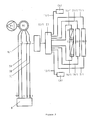
- Each pump unit includes a pump P1, P2, P3 driven by an electric motor M1, M2, M3.
- the electric motor is controlled by a microcontroller E1, E2, E3 proper integrated in the pump unit 1, 2, 3.
- On pump unit 1 is mounted a level detector CN1 and a stop detector CA1.
- the level detector is of electronic type but it could also be of mechanical type in being for example simply a float.
- the level detector CN1 sends a signal to the microcontroller E1 when the water level in the tank C reaches a given high value.
- the stop detector CA1 which can also be electronic or float sends a signal to the microcontroller E1 when the water level in the tank reaches a low level. So does even for detectors CN2, CN3 and CA2, CA3.
- T1, T2, T3 delivery pipes for pumps lead into a common collector 4.
- Pump groups 1, 2, 3 are supplied by electric lines 5, 6, 7 from the network 8.
- the M1 engine three-phase, but which could be single-phase, is powered by three wires 5A, 5B, 5C phase from network 8 via a 9/1 contactor, itself controlled by the micro-controller E1 via a line 10/1.
- the microcontroller E1 receives the signals from the sensor CN1 by via a line 11/1 and the signals from the sensor CA1 by through a line 12/1.
- the E1 microcontroller is connected to a table 13/1 time delay and D1 means of decrementation by a line 14/1 and at a 15/1 over-time table having S1 means of decrement by a line 16/1.
- the E1 microcontroller is also connected by a line 17/1 to a memory 18/1 of state of the sensor CN1 and by a line 19/1 to a 20/1 supertemporization counter which counts the number of times where the pump unit has operated.
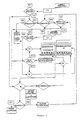
- the cascade of three pump units operates from the next way.
- the pump units 1, 2, 3 are set for the first time in tank C and when the water level reaches one of levels of sensors CN1, CN2 or CN3, one of the pump units or the three pump units start up. Water level lowers until the stop detectors CA1, CA2, CA3 detects it. They send a signal respectively to their microcontroller E1, E2, E3.
- the microcontroller E1 for example, receives timers from table 13/1 a timeout value for example of six seconds, while E2 receives from its timing table another random value that we will assume eight seconds and E3 receives a timeout value of ten seconds.
- memories 18/2 and 18/3 give the order to means D2, D3 of decrease the time delay by one step. If the step is 2 seconds, the durations become equal to 6 seconds and 8 seconds respectively for M2 and M3.
- the microcontroller E1 receives from the counter 20.1 a signal to establish a delay time sent to table 15.1 overtime, 16 seconds higher by example at the largest time delay in table 13.1. That leaves time water to go up to the level detectors CN2 and CN3 even if they are higher than the level detector CN1 and to the pump sets M2 or M3 to enter into action preferentially to the M1 pump unit.
- the detector CN1 will order the means S1 to decrement table 15/1 the 2 second step over-time. As long as group 1 has a overtime, it will not go into action before the action of others groups 2 and 3. However, if the functioning of groups 2 and 3 is not sufficient after the overtime delay to empty tank C, group 1 will go into action. As soon as group 1 is, after being put out of action by the overtime, put back into action, it will be assigned again a random delay time.
- the CN.1 sensor memory 18.1 also gives the command to the microcontroller E1 to inhibit the time table 13.1 if the overtime table 15.1 is, while the M1 motor is switched on voltage, activated n times successively without interruption, by the signals received from the level detector CN1, n being a higher number or equal to 4, since this means that the pump set 1 is alone in tank C.
- n being a higher number or equal to 4, since this means that the pump set 1 is alone in tank C.
- the E1 microcontroller can include means for deactivating the time table 13.1 when the engine is energized after the delay time longer has elapsed.
- microcontrollers described above include the microcontrollers E1, E2, E3 proper and also tables 13.1, 13.2, 13.3 and memories 18.1, 18.2, 18.3 and counters 20.1, 20.2, 20.3. But the microcontrollers could also be microprocessors to which tables, memories and counters would be added. Finally everything can be designed as software.
Landscapes
- Engineering & Computer Science (AREA)
- Mechanical Engineering (AREA)
- General Engineering & Computer Science (AREA)
- Control Of Non-Positive-Displacement Pumps (AREA)
- Control Of Positive-Displacement Pumps (AREA)
- Control Of Multiple Motors (AREA)
- Control Of Electric Motors In General (AREA)
- Diaphragms For Electromechanical Transducers (AREA)
- Transition And Organic Metals Composition Catalysts For Addition Polymerization (AREA)
Abstract
Description
Claims (7)
- Groupe motopompe (1) comprenant une pompe (P1) entraínée par un moteur (M1) électrique commandé par un micro-contrôleur (E1) intégré dans le groupe (1) qui met le moteur (M1) sous tension par des signaux qu'il reçoit d'un détecteur de niveau (CN1) et hors tension par des signaux qu'il reçoit d'un détecteur d'arrêt (CA1), caractérisé en ce que le micro-contrôleur (E1) comprend des moyens (13/1) de temporisation destinés à retarder la mise sous tension du moteur (M1) électrique d'une durée de temporisation choisie aléatoirement parmi des pas de durée progressivement croissants et des moyens (D1) de décrémentation destinés à diminuer d'un pas la durée de temporisation à chaque signal reçu du détecteur de niveau (CN1) pour lequel le moteur (M1) n'est pas mis sous tension.
- Groupe motopompe (1) suivant la revendication 1, caractérisé en ce que le micro-contrôleur (E1) comprend des moyens d'inactivation des moyens (13/1) de temporisation lorsque le moteur (M1) est mis sous tension après cependant que la durée de temporisation la plus longue s'est écoulée.
- Groupe motopompe suivant la revendication 1, caractérisé en ce que le micro-contrôleur (E1) comprend des moyens d'inactivation des moyens (13/1) de temporisation, lorsque le moteur (M1) est mis sous tension au moins 4 fois de suite sans que les moyens (D1) de décrémentation soient entrés en action intermédiairement.
- Groupe motopompe (1) suivant l'une des revendications 1 à 3, caractérisé en ce que le micro-contrôleur (E1) comprend des moyens (15/1) de surtemporisation avec décrémentation (S1) progressive, destinés à retarder la mise sous tension du moteur (M1) d'une durée d'attente supérieure à la plus grande durée de temporisation lorsque le moteur (M1) a été mis sous tension, n fois successivement sans interruption, par les signaux envoyés par le détecteur de niveau (CN1), n étant un nombre entier supérieur ou égal à 2 et, de préférence, supérieur ou égal à 4.
- Groupe motopompe (1) suivant la revendication 4, caractérisé en ce que le micro-contrôleur (E1) comprend des moyens d'inhibition des moyens (13/1) de temporisation et des moyens (15/1) de surtemporisation, lorsque le groupe est entré en action n fois, n étant égal ou supérieur à 2, alors que pourtant les moyens (S1) de surtemporisation étaient en action.
- Cascade de m groupes motopompes, caractérisée en ce que les m groupes sont tel que définies aux revendications 1 à 5 et sont placées dans une même cuve.
- Cascade suivant la revendication 6, caractérisé en ce que m est égal ou supérieur à 3.
Applications Claiming Priority (2)
| Application Number | Priority Date | Filing Date | Title |
|---|---|---|---|
| FR0106107A FR2824601B1 (fr) | 2001-05-09 | 2001-05-09 | Groupe motopompe a temporisation de la mise sous tension du moteur |
| FR0106107 | 2001-05-09 |
Publications (2)
| Publication Number | Publication Date |
|---|---|
| EP1256724A1 true EP1256724A1 (fr) | 2002-11-13 |
| EP1256724B1 EP1256724B1 (fr) | 2006-07-26 |
Family
ID=8863070
Family Applications (1)
| Application Number | Title | Priority Date | Filing Date |
|---|---|---|---|
| EP02290926A Expired - Lifetime EP1256724B1 (fr) | 2001-05-09 | 2002-04-12 | Groupe motopompe à temporisation de la mise sous tension du moteur |
Country Status (7)
| Country | Link |
|---|---|
| EP (1) | EP1256724B1 (fr) |
| AT (1) | ATE334312T1 (fr) |
| DE (1) | DE60213316T2 (fr) |
| DK (1) | DK1256724T3 (fr) |
| ES (1) | ES2265479T3 (fr) |
| FR (1) | FR2824601B1 (fr) |
| PT (1) | PT1256724E (fr) |
Cited By (4)
| Publication number | Priority date | Publication date | Assignee | Title |
|---|---|---|---|---|
| FR2948734A1 (fr) * | 2009-07-31 | 2011-02-04 | Ksb Sas | Groupe motopompe a detecteurs de niveau |
| CN103608592A (zh) * | 2011-06-16 | 2014-02-26 | 赛乐姆知识产权控股有限责任公司 | 用于泵之间的自动相互交替运行的方法 |
| EP3367533A1 (fr) * | 2017-02-27 | 2018-08-29 | Xylem IP Management S.à.r.l. | Procédé pour le contrôle d'une pompe reliée à un réseau de pompes |
| CN115917158A (zh) * | 2020-07-28 | 2023-04-04 | 胡斯华纳有限公司 | 泵的控制接口 |
Families Citing this family (1)
| Publication number | Priority date | Publication date | Assignee | Title |
|---|---|---|---|---|
| US20250180027A1 (en) * | 2023-12-05 | 2025-06-05 | Pentair, Inc. | Pump system with dynamic level control |
Citations (3)
| Publication number | Priority date | Publication date | Assignee | Title |
|---|---|---|---|---|
| US4437811A (en) * | 1980-06-30 | 1984-03-20 | Ebara Corporation | Submersible pump with alternate pump operation control means |
| GB2204153A (en) * | 1987-04-06 | 1988-11-02 | Hitachi Ltd | Automatic water supplying device |
| EP0947702A1 (fr) * | 1998-04-03 | 1999-10-06 | Ksb S.A. | Groupe motopompe submersible à générateur de signaux |
-
2001
- 2001-05-09 FR FR0106107A patent/FR2824601B1/fr not_active Expired - Fee Related
-
2002
- 2002-04-12 ES ES02290926T patent/ES2265479T3/es not_active Expired - Lifetime
- 2002-04-12 AT AT02290926T patent/ATE334312T1/de active
- 2002-04-12 PT PT02290926T patent/PT1256724E/pt unknown
- 2002-04-12 DK DK02290926T patent/DK1256724T3/da active
- 2002-04-12 DE DE60213316T patent/DE60213316T2/de not_active Expired - Lifetime
- 2002-04-12 EP EP02290926A patent/EP1256724B1/fr not_active Expired - Lifetime
Patent Citations (3)
| Publication number | Priority date | Publication date | Assignee | Title |
|---|---|---|---|---|
| US4437811A (en) * | 1980-06-30 | 1984-03-20 | Ebara Corporation | Submersible pump with alternate pump operation control means |
| GB2204153A (en) * | 1987-04-06 | 1988-11-02 | Hitachi Ltd | Automatic water supplying device |
| EP0947702A1 (fr) * | 1998-04-03 | 1999-10-06 | Ksb S.A. | Groupe motopompe submersible à générateur de signaux |
Cited By (14)
| Publication number | Priority date | Publication date | Assignee | Title |
|---|---|---|---|---|
| FR2948734A1 (fr) * | 2009-07-31 | 2011-02-04 | Ksb Sas | Groupe motopompe a detecteurs de niveau |
| EP2295810A1 (fr) * | 2009-07-31 | 2011-03-16 | Ksb S.A.S. | Groupe motopompe à détecteurs de niveau |
| CN103608592A (zh) * | 2011-06-16 | 2014-02-26 | 赛乐姆知识产权控股有限责任公司 | 用于泵之间的自动相互交替运行的方法 |
| KR20140036258A (ko) * | 2011-06-16 | 2014-03-25 | 자일럼 아이피 홀딩스 엘엘씨. | 펌프들을 자동적으로 서로 교대로 작동시키기 위한 방법 |
| US20140134005A1 (en) * | 2011-06-16 | 2014-05-15 | Xylem Ip Holdings Llc | Method for controlling a pump |
| JP2014520230A (ja) * | 2011-06-16 | 2014-08-21 | ザイレム・アイピー・ホールディングズ・エルエルシー | ポンプ間で自動的に相互に交代させるための方法 |
| EP2721302A4 (fr) * | 2011-06-16 | 2015-02-25 | Xylem Ip Holdings Llc | Procédé de commande d'une pompe |
| CN103608592B (zh) * | 2011-06-16 | 2016-08-17 | 赛乐姆知识产权控股有限责任公司 | 用于泵之间的自动相互交替运行的方法 |
| AU2012269768B2 (en) * | 2011-06-16 | 2016-12-01 | Xylem Ip Holdings Llc | Method for automatic mutual alternation between pumps |
| US9995293B2 (en) | 2011-06-16 | 2018-06-12 | Xylem Ip Holdings Llc | Method for controlling a pump |
| EP3367533A1 (fr) * | 2017-02-27 | 2018-08-29 | Xylem IP Management S.à.r.l. | Procédé pour le contrôle d'une pompe reliée à un réseau de pompes |
| WO2018154099A1 (fr) * | 2017-02-27 | 2018-08-30 | Xylem Ip Management S.À R.L. | Procédé de commande d'une pompe connectée à un réseau de pompage |
| CN110366805A (zh) * | 2017-02-27 | 2019-10-22 | 赛莱默欧洲有限公司 | 用于控制连接到泵网络的泵的方法 |
| CN115917158A (zh) * | 2020-07-28 | 2023-04-04 | 胡斯华纳有限公司 | 泵的控制接口 |
Also Published As
| Publication number | Publication date |
|---|---|
| ATE334312T1 (de) | 2006-08-15 |
| PT1256724E (pt) | 2006-12-29 |
| DK1256724T3 (da) | 2006-09-04 |
| DE60213316T2 (de) | 2008-02-28 |
| EP1256724B1 (fr) | 2006-07-26 |
| FR2824601B1 (fr) | 2003-08-08 |
| ES2265479T3 (es) | 2007-02-16 |
| FR2824601A1 (fr) | 2002-11-15 |
| DE60213316D1 (de) | 2006-09-07 |
Similar Documents
| Publication | Publication Date | Title |
|---|---|---|
| FR2747521A1 (fr) | Commande d'un moteur sans collecteur | |
| EP1256724B1 (fr) | Groupe motopompe à temporisation de la mise sous tension du moteur | |
| FR2918427A1 (fr) | Procede de reglage de la position d'un actionneur d'embrayage | |
| FR2493004A1 (fr) | Microprocesseur a circuit de remise a l'etat initial | |
| FR2625384A1 (fr) | Circuit electronique de demarrage pour moteur a courant alternatif | |
| FR2829315A1 (fr) | Procede et appareil de commande des moteurs sans balais | |
| JPH09189472A (ja) | 冷蔵庫のディスペンサーに使用されるポンプモータの駆動方法及び装置 | |
| FR2586522A1 (fr) | Dispositif de rotissage programme a l'aide d'un recipient de rotissage | |
| EP0936728B1 (fr) | Commande d'un moteur sans collecteur susceptible de comporter des dissymétries | |
| EP3213404B1 (fr) | Dispositif de commande d'une machine electrique tournante synchrone polyphasee, et machine electrique reversible de vehicule automobile corres | |
| EP0209421B1 (fr) | Appareil de répartition de puissance automatique pour installations électriques domestiques et installations analogues | |
| EP1286570A1 (fr) | Dispositif de commande perfectionnée d'une alimentation électrique, notamment pour candélabres d'éclairage public | |
| WO2020001904A1 (fr) | Moteur electrique a courant continu sans balai et procede de commande associe | |
| EP0252816B1 (fr) | Programmateur de commande de lave-linge à microprocesseur, et composant électromécanique | |
| EP2767640B1 (fr) | Dispositif pour commander électroniquement le rinçage d'un urinoir. | |
| EP2295810A1 (fr) | Groupe motopompe à détecteurs de niveau | |
| CA2193730A1 (fr) | Procede de commande d'un gradateur de tension pour l'alimentation d'un moteur a induction | |
| EP4219948B1 (fr) | Pompe à capteur de vibrations et son procédé de fabrication | |
| EP0936577B1 (fr) | Installation mettant en oeuvre une procédé de contrôle du bon fonctionnement d'un appareil par comparaison avec le fonctionnement d'un autre appareil | |
| EP0903498B1 (fr) | Groupe electropompe submersible et procede pour le faire fonctionner | |
| FR2483644A1 (fr) | Horloge de minutage a commande par touches | |
| EP4112859B1 (fr) | Dispositif d'entraînement motorisé pour une installation domotique de fermeture | |
| CH366891A (fr) | Procédé pour le démarrage et le réglage de la vitesse d'une machine électrique synchrone et installation pour la mise en oeuvre de ce procédé | |
| FR2779587A1 (fr) | Procede pour alimenter un moteur electrique polyphase a commutation electronique, et circuit d'alimentation pour sa mise en oeuvre | |
| FR2554253A1 (fr) | Procedes et dispositifs pour commander automatiquement une pompe |
Legal Events
| Date | Code | Title | Description |
|---|---|---|---|
| PUAI | Public reference made under article 153(3) epc to a published international application that has entered the european phase |
Free format text: ORIGINAL CODE: 0009012 |
|
| AK | Designated contracting states |
Kind code of ref document: A1 Designated state(s): AT BE CH CY DE DK ES FI FR GB GR IE IT LI LU MC NL PT SE TR |
|
| AX | Request for extension of the european patent |
Free format text: AL;LT;LV;MK;RO;SI |
|
| RAP1 | Party data changed (applicant data changed or rights of an application transferred) |
Owner name: KSB S.A.S |
|
| 17P | Request for examination filed |
Effective date: 20030513 |
|
| AKX | Designation fees paid |
Designated state(s): AT BE CH CY DE DK ES FI FR GB GR IE IT LI LU MC NL PT SE TR |
|
| GRAP | Despatch of communication of intention to grant a patent |
Free format text: ORIGINAL CODE: EPIDOSNIGR1 |
|
| GRAS | Grant fee paid |
Free format text: ORIGINAL CODE: EPIDOSNIGR3 |
|
| GRAA | (expected) grant |
Free format text: ORIGINAL CODE: 0009210 |
|
| AK | Designated contracting states |
Kind code of ref document: B1 Designated state(s): AT BE CH CY DE DK ES FI FR GB GR IE IT LI LU MC NL PT SE TR |
|
| PG25 | Lapsed in a contracting state [announced via postgrant information from national office to epo] |
Ref country code: IT Free format text: LAPSE BECAUSE OF FAILURE TO SUBMIT A TRANSLATION OF THE DESCRIPTION OR TO PAY THE FEE WITHIN THE PRESCRIBED TIME-LIMIT;WARNING: LAPSES OF ITALIAN PATENTS WITH EFFECTIVE DATE BEFORE 2007 MAY HAVE OCCURRED AT ANY TIME BEFORE 2007. THE CORRECT EFFECTIVE DATE MAY BE DIFFERENT FROM THE ONE RECORDED. Effective date: 20060726 |
|
| REG | Reference to a national code |
Ref country code: GB Ref legal event code: FG4D Free format text: NOT ENGLISH |
|
| REG | Reference to a national code |
Ref country code: CH Ref legal event code: EP Ref country code: CH Ref legal event code: NV Representative=s name: E. BLUM & CO. PATENTANWAELTE |
|
| REG | Reference to a national code |
Ref country code: IE Ref legal event code: FG4D Free format text: LANGUAGE OF EP DOCUMENT: FRENCH |
|
| REG | Reference to a national code |
Ref country code: DK Ref legal event code: T3 |
|
| REF | Corresponds to: |
Ref document number: 60213316 Country of ref document: DE Date of ref document: 20060907 Kind code of ref document: P |
|
| GBT | Gb: translation of ep patent filed (gb section 77(6)(a)/1977) |
Effective date: 20061002 |
|
| REG | Reference to a national code |
Ref country code: SE Ref legal event code: TRGR |
|
| REG | Reference to a national code |
Ref country code: PT Ref legal event code: SC4A Free format text: AVAILABILITY OF NATIONAL TRANSLATION Effective date: 20061025 |
|
| REG | Reference to a national code |
Ref country code: ES Ref legal event code: FG2A Ref document number: 2265479 Country of ref document: ES Kind code of ref document: T3 |
|
| PLBE | No opposition filed within time limit |
Free format text: ORIGINAL CODE: 0009261 |
|
| STAA | Information on the status of an ep patent application or granted ep patent |
Free format text: STATUS: NO OPPOSITION FILED WITHIN TIME LIMIT |
|
| 26N | No opposition filed |
Effective date: 20070427 |
|
| REG | Reference to a national code |
Ref country code: CH Ref legal event code: PFA Owner name: KSB S.A.S Free format text: KSB S.A.S#4, ALLEE DES BARBANNIERS#92230 GENNEVILLIERS (FR) -TRANSFER TO- KSB S.A.S#4, ALLEE DES BARBANNIERS#92230 GENNEVILLIERS (FR) |
|
| PG25 | Lapsed in a contracting state [announced via postgrant information from national office to epo] |
Ref country code: GR Free format text: LAPSE BECAUSE OF FAILURE TO SUBMIT A TRANSLATION OF THE DESCRIPTION OR TO PAY THE FEE WITHIN THE PRESCRIBED TIME-LIMIT Effective date: 20061027 |
|
| PG25 | Lapsed in a contracting state [announced via postgrant information from national office to epo] |
Ref country code: MC Free format text: LAPSE BECAUSE OF NON-PAYMENT OF DUE FEES Effective date: 20070430 |
|
| PG25 | Lapsed in a contracting state [announced via postgrant information from national office to epo] |
Ref country code: LU Free format text: LAPSE BECAUSE OF NON-PAYMENT OF DUE FEES Effective date: 20070412 Ref country code: CY Free format text: LAPSE BECAUSE OF FAILURE TO SUBMIT A TRANSLATION OF THE DESCRIPTION OR TO PAY THE FEE WITHIN THE PRESCRIBED TIME-LIMIT Effective date: 20060726 |
|
| PG25 | Lapsed in a contracting state [announced via postgrant information from national office to epo] |
Ref country code: TR Free format text: LAPSE BECAUSE OF FAILURE TO SUBMIT A TRANSLATION OF THE DESCRIPTION OR TO PAY THE FEE WITHIN THE PRESCRIBED TIME-LIMIT Effective date: 20060726 |
|
| PGFP | Annual fee paid to national office [announced via postgrant information from national office to epo] |
Ref country code: ES Payment date: 20120420 Year of fee payment: 11 |
|
| PGFP | Annual fee paid to national office [announced via postgrant information from national office to epo] |
Ref country code: AT Payment date: 20120425 Year of fee payment: 11 |
|
| PGFP | Annual fee paid to national office [announced via postgrant information from national office to epo] |
Ref country code: PT Payment date: 20130328 Year of fee payment: 12 |
|
| PGFP | Annual fee paid to national office [announced via postgrant information from national office to epo] |
Ref country code: BE Payment date: 20130424 Year of fee payment: 12 Ref country code: DE Payment date: 20130409 Year of fee payment: 12 Ref country code: SE Payment date: 20130426 Year of fee payment: 12 Ref country code: IE Payment date: 20130419 Year of fee payment: 12 Ref country code: GB Payment date: 20130423 Year of fee payment: 12 Ref country code: CH Payment date: 20130429 Year of fee payment: 12 Ref country code: DK Payment date: 20130424 Year of fee payment: 12 |
|
| PGFP | Annual fee paid to national office [announced via postgrant information from national office to epo] |
Ref country code: NL Payment date: 20130427 Year of fee payment: 12 Ref country code: FR Payment date: 20130523 Year of fee payment: 12 Ref country code: FI Payment date: 20130424 Year of fee payment: 12 Ref country code: IT Payment date: 20130420 Year of fee payment: 12 |
|
| REG | Reference to a national code |
Ref country code: PT Ref legal event code: MM4A Free format text: LAPSE DUE TO NON-PAYMENT OF FEES Effective date: 20141013 |
|
| REG | Reference to a national code |
Ref country code: DE Ref legal event code: R119 Ref document number: 60213316 Country of ref document: DE |
|
| REG | Reference to a national code |
Ref country code: DK Ref legal event code: EBP Effective date: 20140430 |
|
| REG | Reference to a national code |
Ref country code: NL Ref legal event code: V1 Effective date: 20141101 |
|
| REG | Reference to a national code |
Ref country code: CH Ref legal event code: PL |
|
| REG | Reference to a national code |
Ref country code: SE Ref legal event code: EUG |
|
| REG | Reference to a national code |
Ref country code: AT Ref legal event code: MM01 Ref document number: 334312 Country of ref document: AT Kind code of ref document: T Effective date: 20140412 |
|
| GBPC | Gb: european patent ceased through non-payment of renewal fee |
Effective date: 20140412 |
|
| REG | Reference to a national code |
Ref country code: DE Ref legal event code: R119 Ref document number: 60213316 Country of ref document: DE Effective date: 20141101 |
|
| REG | Reference to a national code |
Ref country code: FR Ref legal event code: ST Effective date: 20141231 |
|
| REG | Reference to a national code |
Ref country code: IE Ref legal event code: MM4A |
|
| PG25 | Lapsed in a contracting state [announced via postgrant information from national office to epo] |
Ref country code: SE Free format text: LAPSE BECAUSE OF NON-PAYMENT OF DUE FEES Effective date: 20140413 Ref country code: DE Free format text: LAPSE BECAUSE OF NON-PAYMENT OF DUE FEES Effective date: 20141101 Ref country code: GB Free format text: LAPSE BECAUSE OF NON-PAYMENT OF DUE FEES Effective date: 20140412 Ref country code: PT Free format text: LAPSE BECAUSE OF NON-PAYMENT OF DUE FEES Effective date: 20141013 Ref country code: LI Free format text: LAPSE BECAUSE OF NON-PAYMENT OF DUE FEES Effective date: 20140430 Ref country code: CH Free format text: LAPSE BECAUSE OF NON-PAYMENT OF DUE FEES Effective date: 20140430 Ref country code: FI Free format text: LAPSE BECAUSE OF NON-PAYMENT OF DUE FEES Effective date: 20140412 |
|
| PG25 | Lapsed in a contracting state [announced via postgrant information from national office to epo] |
Ref country code: NL Free format text: LAPSE BECAUSE OF NON-PAYMENT OF DUE FEES Effective date: 20141101 Ref country code: FR Free format text: LAPSE BECAUSE OF NON-PAYMENT OF DUE FEES Effective date: 20140430 Ref country code: AT Free format text: LAPSE BECAUSE OF NON-PAYMENT OF DUE FEES Effective date: 20140412 |
|
| PG25 | Lapsed in a contracting state [announced via postgrant information from national office to epo] |
Ref country code: IT Free format text: LAPSE BECAUSE OF NON-PAYMENT OF DUE FEES Effective date: 20140412 |
|
| PG25 | Lapsed in a contracting state [announced via postgrant information from national office to epo] |
Ref country code: DK Free format text: LAPSE BECAUSE OF NON-PAYMENT OF DUE FEES Effective date: 20140430 Ref country code: IE Free format text: LAPSE BECAUSE OF NON-PAYMENT OF DUE FEES Effective date: 20140412 |
|
| REG | Reference to a national code |
Ref country code: ES Ref legal event code: FD2A Effective date: 20150527 |
|
| PG25 | Lapsed in a contracting state [announced via postgrant information from national office to epo] |
Ref country code: ES Free format text: LAPSE BECAUSE OF NON-PAYMENT OF DUE FEES Effective date: 20140413 |
|
| PG25 | Lapsed in a contracting state [announced via postgrant information from national office to epo] |
Ref country code: BE Free format text: LAPSE BECAUSE OF NON-PAYMENT OF DUE FEES Effective date: 20140430 |