EP1256554A1 - Fibre optique à saut d'indice à gaine et coeur dopés, préforme et procédé de fabrication pour une telle fibre - Google Patents
Fibre optique à saut d'indice à gaine et coeur dopés, préforme et procédé de fabrication pour une telle fibre Download PDFInfo
- Publication number
- EP1256554A1 EP1256554A1 EP02291076A EP02291076A EP1256554A1 EP 1256554 A1 EP1256554 A1 EP 1256554A1 EP 02291076 A EP02291076 A EP 02291076A EP 02291076 A EP02291076 A EP 02291076A EP 1256554 A1 EP1256554 A1 EP 1256554A1
- Authority
- EP
- European Patent Office
- Prior art keywords
- index
- deposition tube
- sheath
- tube
- optical fiber
- Prior art date
- Legal status (The legal status is an assumption and is not a legal conclusion. Google has not performed a legal analysis and makes no representation as to the accuracy of the status listed.)
- Granted
Links
Images
Classifications
-
- C—CHEMISTRY; METALLURGY
- C03—GLASS; MINERAL OR SLAG WOOL
- C03B—MANUFACTURE, SHAPING, OR SUPPLEMENTARY PROCESSES
- C03B37/00—Manufacture or treatment of flakes, fibres, or filaments from softened glass, minerals, or slags
- C03B37/01—Manufacture of glass fibres or filaments
- C03B37/012—Manufacture of preforms for drawing fibres or filaments
- C03B37/014—Manufacture of preforms for drawing fibres or filaments made entirely or partially by chemical means, e.g. vapour phase deposition of bulk porous glass either by outside vapour deposition [OVD], or by outside vapour phase oxidation [OVPO] or by vapour axial deposition [VAD]
- C03B37/018—Manufacture of preforms for drawing fibres or filaments made entirely or partially by chemical means, e.g. vapour phase deposition of bulk porous glass either by outside vapour deposition [OVD], or by outside vapour phase oxidation [OVPO] or by vapour axial deposition [VAD] by glass deposition on a glass substrate, e.g. by inside-, modified-, plasma- or plasma modified- chemical vapour deposition [ICVD, MCVD, PCVD, PMCVD], i.e. by thin layer coating on the inside or outside of a glass tube or on a glass rod
- C03B37/01884—Means for supporting, rotating and translating tubes or rods being formed, e.g. lathes
- C03B37/01892—Deposition substrates, e.g. tubes, mandrels
-
- C—CHEMISTRY; METALLURGY
- C03—GLASS; MINERAL OR SLAG WOOL
- C03B—MANUFACTURE, SHAPING, OR SUPPLEMENTARY PROCESSES
- C03B37/00—Manufacture or treatment of flakes, fibres, or filaments from softened glass, minerals, or slags
- C03B37/01—Manufacture of glass fibres or filaments
- C03B37/012—Manufacture of preforms for drawing fibres or filaments
- C03B37/01205—Manufacture of preforms for drawing fibres or filaments starting from tubes, rods, fibres or filaments
-
- G—PHYSICS
- G02—OPTICS
- G02B—OPTICAL ELEMENTS, SYSTEMS OR APPARATUS
- G02B6/00—Light guides; Structural details of arrangements comprising light guides and other optical elements, e.g. couplings
- G02B6/02—Optical fibres with cladding with or without a coating
-
- G—PHYSICS
- G02—OPTICS
- G02B—OPTICAL ELEMENTS, SYSTEMS OR APPARATUS
- G02B6/00—Light guides; Structural details of arrangements comprising light guides and other optical elements, e.g. couplings
- G02B6/02—Optical fibres with cladding with or without a coating
- G02B6/02004—Optical fibres with cladding with or without a coating characterised by the core effective area or mode field radius
- G02B6/02009—Large effective area or mode field radius, e.g. to reduce nonlinear effects in single mode fibres
- G02B6/02014—Effective area greater than 60 square microns in the C band, i.e. 1530-1565 nm
- G02B6/02019—Effective area greater than 90 square microns in the C band, i.e. 1530-1565 nm
-
- G—PHYSICS
- G02—OPTICS
- G02B—OPTICAL ELEMENTS, SYSTEMS OR APPARATUS
- G02B6/00—Light guides; Structural details of arrangements comprising light guides and other optical elements, e.g. couplings
- G02B6/02—Optical fibres with cladding with or without a coating
- G02B6/036—Optical fibres with cladding with or without a coating core or cladding comprising multiple layers
- G02B6/03694—Multiple layers differing in properties other than the refractive index, e.g. attenuation, diffusion, stress properties
-
- C—CHEMISTRY; METALLURGY
- C03—GLASS; MINERAL OR SLAG WOOL
- C03B—MANUFACTURE, SHAPING, OR SUPPLEMENTARY PROCESSES
- C03B2201/00—Type of glass produced
- C03B2201/06—Doped silica-based glasses
- C03B2201/08—Doped silica-based glasses doped with boron or fluorine or other refractive index decreasing dopant
- C03B2201/12—Doped silica-based glasses doped with boron or fluorine or other refractive index decreasing dopant doped with fluorine
-
- G—PHYSICS
- G02—OPTICS
- G02B—OPTICAL ELEMENTS, SYSTEMS OR APPARATUS
- G02B6/00—Light guides; Structural details of arrangements comprising light guides and other optical elements, e.g. couplings
- G02B6/02—Optical fibres with cladding with or without a coating
- G02B6/02214—Optical fibres with cladding with or without a coating tailored to obtain the desired dispersion, e.g. dispersion shifted, dispersion flattened
- G02B6/02219—Characterised by the wavelength dispersion properties in the silica low loss window around 1550 nm, i.e. S, C, L and U bands from 1460-1675 nm
- G02B6/02228—Dispersion flattened fibres, i.e. having a low dispersion variation over an extended wavelength range
- G02B6/02238—Low dispersion slope fibres
- G02B6/02242—Low dispersion slope fibres having a dispersion slope <0.06 ps/km/nm2
-
- G—PHYSICS
- G02—OPTICS
- G02B—OPTICAL ELEMENTS, SYSTEMS OR APPARATUS
- G02B6/00—Light guides; Structural details of arrangements comprising light guides and other optical elements, e.g. couplings
- G02B6/02—Optical fibres with cladding with or without a coating
- G02B6/02214—Optical fibres with cladding with or without a coating tailored to obtain the desired dispersion, e.g. dispersion shifted, dispersion flattened
- G02B6/02219—Characterised by the wavelength dispersion properties in the silica low loss window around 1550 nm, i.e. S, C, L and U bands from 1460-1675 nm
- G02B6/02266—Positive dispersion fibres at 1550 nm
-
- G—PHYSICS
- G02—OPTICS
- G02B—OPTICAL ELEMENTS, SYSTEMS OR APPARATUS
- G02B6/00—Light guides; Structural details of arrangements comprising light guides and other optical elements, e.g. couplings
- G02B6/02—Optical fibres with cladding with or without a coating
- G02B6/02295—Microstructured optical fibre
- G02B6/023—Microstructured optical fibre having different index layers arranged around the core for guiding light by reflection, i.e. 1D crystal, e.g. omniguide
-
- G—PHYSICS
- G02—OPTICS
- G02B—OPTICAL ELEMENTS, SYSTEMS OR APPARATUS
- G02B6/00—Light guides; Structural details of arrangements comprising light guides and other optical elements, e.g. couplings
- G02B6/02—Optical fibres with cladding with or without a coating
- G02B6/036—Optical fibres with cladding with or without a coating core or cladding comprising multiple layers
- G02B6/03616—Optical fibres characterised both by the number of different refractive index layers around the central core segment, i.e. around the innermost high index core layer, and their relative refractive index difference
- G02B6/03688—Optical fibres characterised both by the number of different refractive index layers around the central core segment, i.e. around the innermost high index core layer, and their relative refractive index difference having 5 or more layers
Definitions
- the present invention relates to the field of fiber transmissions optics, and more specifically, index hopping optical fibers used as line fiber in such transmission systems.
- the index profile is generally qualified in function of the shape of the graph of the function which associates with the radius of the fiber the index of refraction.
- index hopping fibers also called SMF fibers (acronym for "Single Mode Fiber”).
- SMF fibers Single Mode Fiber
- the applicant thus markets under ASMF 200 reference a single-mode index-hopping fiber having a wavelength ⁇ 0 for canceling the chromatic dispersion between 1300 and 1320 nm, and a chromatic dispersion less than or equal to 3.5 ps / (nm.km) in a range of 1285-1330 nm, and 17 ps / (nm.km) at 1550 nm.
- the chromatic dispersion slope at 1550 nm is of the order of 0.06 ps / (nm 2 .km).
- WO-A-00 36443 describes an index-hopping optical fiber, having a core index higher than that of the sheath. This is surrounded by a layer of carbon.
- the heart has a diameter between 9.5 and 12.0 ⁇ m.
- the relative difference index between the core and the sheath is between 0.3 and 0.5%. It is stated in this document that fiber can be made from silica, by doping the heart to germanium, with a silica sheath; an alternative is to boost the fluorine sheath, using a silica core.
- the doping of germanium core requires high concentrations of germanium - typically greater than 5% by weight - to achieve the required index difference compared to a silica sheath. Such germanium concentrations increase the attenuation in the fiber.
- the manufacture of a core fiber silica and doped sheath involves using for manufacturing an axial vapor deposition technique (VAD or "Vapor Axial Deposition ", or an external phase oxidation technique steam (OVPO or "Outside Vapor Phase Oxidation" in English).
- VAD axial vapor deposition technique
- OVPO external phase oxidation technique steam
- Fiber is manufactured using a VAD technique.
- MCVD modified chemical vapor deposition
- a tube for depositing silica layers containing dopants allowing to vary the index.
- the tube is then shrunk or contracted to form a first preform.
- This first preform is introduced into one or more sleeves, which are shrunk or contracted to be applied against the first preform.
- the preform thus obtained is stretched to form the fiber.
- EP-A-0 972 752 describes a manufacture by MCVD and proposes to deposit inside a deposition tube successive layers of sheath material and core material. After contraction, the deposition tube is introduced into one or more sleeves; it is proposed that the inner sleeve has a doping lowering the index to form a buried sheath fiber.
- the sheath deposited inside the deposition tube can be doped with fluorine, the core being doped with germanium. If the purity of the deposition tube is sufficient, it is possible to avoid deposition of the sheath.
- the deposition tube is a glass tube with a concentration of OH ions - less than 0.05 ppm by mass.
- US-A-4,566,754 or US-A-5,692,087 also propose an index-hopping fiber manufactured by MCVD, by depositing in a silica deposition tube a sheath doped with fluorine and a core doped with germanium.
- US-A-5,942,296 suggests, for the same type of preform, to facilitate the stretching of the preform by acting on the viscosity and the thermal conductivity of the silica deposition tube and the sleeve (s) surrounding it. This solution allows to avoid heating the heart of the preform. It is specified in this document that the manufacturing cost by MCVD decreases when the thickness of the fluorine-doped sheath decreases.
- EP-A-0 899 243 also proposes an index-hopping fiber having a germanium doped heart, fluorine doped inner sheath and sheath exterior in non-doped silica. This request proposes to stretch the fiber at a speed greater than 20 g / min.
- EP-A-0 863 108 describes a process for manufacturing a preform by deposition at plasma from a refill outside a deposition tube.
- the difference between the index of the deposition tube and the index of silica is less than -0.5.10 -3 .
- the difference between the index of the heart and the index of the inner sheath is advantageously between 4.3.10 -3 and 5.10 -3 .
- a refill with an index can be provided substantially equal to the index of the deposition tube, or a sleeve having a index substantially equal to the index of the deposition tube.
- the optical fiber may have a cladding whose index difference compared to the silica index is less than -0.5.10 -3 and a relative index difference between the index of the inner cladding and the index sheath less than 0.02% in absolute value.
- the inner sheath is characterized by quasi-periodic index variations of between 0.3.10 -3 and 0.5.10 -3 in absolute value, having symmetry around the axis of the fiber with a periodicity of the order of 0.6 to 1.4 ⁇ m.
- This internal sheath can be doped from C 2 F 6 , and in this case, the speed of variation of the index given by the ratio between the peak-to-peak difference of the index and the half-period of the variations is between 0.4.10 -3 ⁇ m -1 and 1.7.10 -3 ⁇ m -1 .
- the inner cladding can also be doped from SiF 4 , and in this case, the period is unchanged and the ratio between the absolute peak-to-peak deviation of the index and the half-period of the variations is between 0.2.10 -3 ⁇ m -1 and 0.7.10 -3 ⁇ m -1 .
- the speed of variation of index in the sheath is also advantageous for the speed of variation of index in the sheath to be less than 0.1 ⁇ 10 -3 ⁇ m -1 .
- the fiber can also have an effective surface greater than or equal to 90 ⁇ m 2 at the wavelength of 1.55 ⁇ m, or a theoretical cut-off wavelength less than or equal to 1.65 ⁇ m.
- the invention proposes, for the manufacture by MCVD of a jump optical fiber index, to use a deposition tube with a dopant lowering the index; in this tube is deposited a doped inner sheath having substantially the index of the tube deposition, then a doped core having an index greater than the index of the cladding and the deposition tube. After shrinking, it is still advantageous to provide a refill which is also doped to lower the index to an index close to the index of the tube deposit.
- the fiber obtained by stretching a preform produced according to this process has a core, an inner sheath which corresponds to the doped inner sheath deposited inside the deposition tube and a sheath which corresponds to the deposition tube; it is possible on the fiber thus obtained to distinguish the sheath, the inner sheath and the fiber core.
- the sheath comes from the deposition tube, and has an index which is substantially constant; at the very least, the cladding has no reason to exhibit substantially periodic variations in the index following a symmetry of revolution around the axis of the fiber.
- the refill or the sleeve the index of which does not exceed the index of the sheath by more than 0.5 ⁇ 10 -3 , does not present substantially periodic variations in the index either.
- the inner sheath results from CVD deposition inside the deposition tube.
- the inner sheath in fact has a plurality of interfaces or undulations of low amplitude index. It is therefore possible to determine on an optical fiber if there is a sheath and an inner sheath.
- the level of curvature losses is an important characteristic to consider when making an optical fiber.
- the losses by curvature depend on the index of the cladding and on the ratio r 2 / r 1 which designates the ratio of the radius r 2 of the start of the cladding starting from the axis of the fiber at the core radius r 1 .
- the curvature losses increase when the ratio r 2 / r 1 decreases.
- the curvature losses increase with the cladding index.
- the radius r 2 In order to keep a low level of curvature losses - a level below 10 -5 dB / m at a radius of 30 mm - the radius r 2 must remain greater than a minimum value r 2m which is all the higher as l sheath index is high. Assuming that the index of the cladding remains greater than or equal to the index of the inner cladding, the value of r 2m is minimum when the index of the cladding is equal to the index of the inner cladding. This is particularly the case of the fibers of the invention where the index of the deposition tube and of the refill is substantially equal to the index of the inner sheath.
- the solution of the invention has the advantage of having a sheath and refill index substantially equal to the index of the internal sheath and therefore makes it possible to considerably limit the thickness of the internal sheath by reducing comparatively the manufacturing cost.
- the role of the inner sheath is mainly to reduce the contribution of the deposition tube to the spectral attenuation, this contribution being proportional to the power of the optical field propagating in the tube and to the absorbance of the tube at the operating wavelength.
- the invention has another advantage regarding spectral attenuation.
- the low proportion of Germanium dopant present in the deposited layers of the core limits the Rayleigh scattering by the fiber core and consequently limits the spectral attenuation.
- ⁇ n c the difference between the index n c of the core and the index n g of the sheath.
- the amount of Germanium to be deposited in the core of a fiber of the invention is proportional to (n c -n si ) and not to (n c -n g ) hence the advantage of using a doped sheath Fluoride with a lower index than that of silica.
- a doped deposition tube is used to have an index lower than that of silica: the doping can be fluorine doping, in a proportion of between 2500 and 3500 ppm by mass, which has the effect of lowering the index of tube at values lower than -0.5.10 -3 compared to the silica index.
- the deposition tube typically has an inside diameter of 34 mm, an outside diameter of 39 mm, and a length of 1,300 to 1,690 mm.
- the deposition tube sold under the reference F320 HERAEUS can be used.
- An inner sheath is formed inside the deposition tube, which is doped to lower the index relative to the index of silica.
- the inner sheath has an index close to the index of the deposition tube. It is advantageous for the inner sheath to have an index equal to that of the deposition tube; the deviation of the index of the inner sheath from the index of the deposition tube is acceptable if it remains between -0.3.10 -3 and 0. In relative terms, it is advantageous if the relative difference between the index of the inner sheath and the index of the deposition tube is less than 0.02% in absolute value. Such deviations have in fact only a limited impact on the transmission properties of the optical fiber obtained subsequently. It is possible in particular to use fluorine doping to lower the index of the sheath, in a proportion of 0.3 to 1% by weight of fluorine. To form this inner sheath, known techniques of chemical vapor deposition are used.
- a core is then formed inside the deposition tube which is doped to increase the index relative to the index of silica.
- the difference between the index of the heart and the index of the inner sheath is between 4.3.10 -3 and 5.10 -3 .
- these values correspond to differences in index between 3.3.10 -3 and 4.10 -3 relative to the index of silica when the difference in index between the inner cladding and the index of silica is -1.10 -3 .
- the preform After having deposited the inner sheath and the core in the deposition tube, the preform is shrunk so as to close the opening for passage of the gases in the deposition tube.
- a sleeve or a refill can be placed around the deposition tube, in a manner known per se: a sleeve is shrunk around the preform, while a refill can be deposited by CVD or by plasma deposition; the sleeve has a substantially constant index, without undulations; a refill can also have undulations, which depend if necessary on the manufacturing process, for example variations in the dopant. It is advantageous that the index of the sleeve or of the refill is also close to the index of the deposition tube.
- the sleeve or the refill can for this purpose be doped, for example with fluorine.
- a difference of less than 0.3.10 -3 between the index of the sleeve or of the refill and the index of the deposition tube is acceptable.
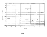
- the drawing of such a preform makes it possible to obtain a fiber having the set point index profile shown in FIG. 1.
- the distance r is plotted in the center of the fiber, and on the ordinates the difference between the refractive index and the refractive index of the fiber cladding.
- the profile of Figure 1 is a jump index profile. We recognize around the axis of the fiber the fiber core which has a higher index than that of silica; the radius r 1 of the core is between 4.8 and 5.7 ⁇ m.
- the fiber Around the core, the fiber has a substantially constant index and lower than that of silica. Between the rays r 1 and r 2 extends the part of the fiber which corresponds to the inner sheath; r 2 is typically between 12.5 and 15.7 ⁇ m. This part of the fiber is hereinafter called “inner sheath"; as explained above, it is distinguished from the part of the fiber which corresponds to the deposition tube, by the presence of corrugations of index. These undulations are quasi-periodic variations of the value of the index along the radius of the index profile, ie over a radius of the fiber; the period depends on the thickness of the layers deposited in the deposition tube, and on the dimensional variations during the shrinking of the preform then during the fiberizing.
- Typical values of the variations for C 2 F 6 used as dopant are between 0.3 and 0.5.10 -3 ; taking into account the quasi-period of the ripples, the ratio between this peak-to-peak variation and the half-period is between 0.4.10 -3 ⁇ m -1 and 1.7.10 -3 ⁇ m -1 .
- Typical values of the variations for SiF 4 used as a dopant are lower, and are typically around 0.2.10 -3 , which leads to a ratio of the variations peak to peak to the half-period between 0.2.10 - 3 and 0.7.10 -3 ⁇ m -1 .
- Germanium at a rate of 0.3 to 1% by weight and / or Phosphorus at a rate of 0.3 to 0.4% by weight. Germanium makes it possible to limit the spectral attenuation, while phosphorus ensures better vitrification of the deposit.
- sheath The part corresponding to the deposition tube is described hereinafter as "sheath".
- the variations in cladding index are linked to the homogeneity of the index of the deposition tube. In the sheath, the index generally varies slowly and these variations generally remain less than 0.1.10 -3 . However, unlike the inner sheath, these variations are not periodic.
- the speed of variation - measured radially over a distance of 1 ⁇ m - is less than 0.1.10 -3 ⁇ m -1 , in other words is lower than the radial variations of index in the inner sheath.
- the difference in index between the fiber core and the inner sheath - the fiber index jump - is typically between 4.3.10 -3 and 5.10 -3 .
- Curvature losses are measured by winding the fiber around a 10 mm diameter sleeve.
- the invention makes it possible to obtain by MCVD a fiber with index jump, having a large effective area and a low attenuation; the attenuation values obtained result in particular from the concentration of dopant in the fiber core, which is lower than in the prior art fibers.
- the process of the invention ensures low cost manufacturing due to the reduced thickness of the sheath inside to deposit in the deposit tube.
- the fiber of the invention can be used in all known uses of index hopping fibers, and in particular as line fiber in optical fiber transmission systems. It generally has the following propagation characteristics. For a fluorine-doped tube index less than or equal to -0.5.10 -3 , and for core index values relative to the tube index between 4.10 -3 and 5.10 -3 , the jump values index relative to the silica index remain below 4.5.10 -3 . As explained above, this value is less than the value obtained for a conventional index hopping fiber with a silica cladding; this drop in the core index compared to the index of silica in the proposed fiber contributes to the reduction of Rayleigh diffusion in the fiber.
- the power of the mode propagating in the deposition tube is between 0.025 and 1.4% of the total power propagating in the fiber and the attenuation increment by absorption of the tube deposit remains below about 0.01 dB / km.
Landscapes
- Physics & Mathematics (AREA)
- Chemical & Material Sciences (AREA)
- Engineering & Computer Science (AREA)
- Optics & Photonics (AREA)
- General Physics & Mathematics (AREA)
- General Life Sciences & Earth Sciences (AREA)
- Geochemistry & Mineralogy (AREA)
- Manufacturing & Machinery (AREA)
- Materials Engineering (AREA)
- Organic Chemistry (AREA)
- Life Sciences & Earth Sciences (AREA)
- General Chemical & Material Sciences (AREA)
- Chemical Kinetics & Catalysis (AREA)
- Manufacture, Treatment Of Glass Fibers (AREA)
- Glass Compositions (AREA)
- Surface Treatment Of Glass Fibres Or Filaments (AREA)
- Optical Fibers, Optical Fiber Cores, And Optical Fiber Bundles (AREA)
Abstract
Description
- la formation par dépôt chimique en phase vapeur à l'intérieur d'un tube de dépôt présentant un indice inférieur à l'indice de la silice d'une gaine intérieure présentant un indice sensiblement égal à l'indice du tube de dépôt, la différence relative entre l'indice de la gaine intérieure et l'indice du tube de dépôt étant en valeur absolue inférieure à 0,02 %,
- la formation par dépôt chimique en phase vapeur à l'intérieur de la gaine d'un coeur présentant un indice supérieur à l'indice de la silice. Dans un mode de réalisation, la différence entre l'indice du tube de dépôt et l'indice de la silice est inférieure à -0,5.10-3.Dans un autre mode de réalisation, la différence entre l'indice du coeur et l'indice de la gaine intérieure est comprise entre 4,3.10-3 et 5.10-3.Le procédé peut encore comprendre
- le rétreint du tube de dépôt avec la gaine intérieure et le coeur ; et
- le dépôt d'une recharge déposée par plasma autour du tube rétreint, la recharge présentant un indice sensiblement égal à l'indice du tube de dépôt. Il est aussi possible de prévoir
- le rétreint du tube de dépôt avec la gaine intérieure et le coeur ; et
- le rétreint d'un manchon autour du tube rétreint, le manchon présentant un indice sensiblement égal à l'indice du tube de dépôt.
- un tube de dépôt présentant un indice inférieur à l'indice de la silice ;
- une gaine intérieure au tube de dépôt présentant un indice sensiblement égal à l'indice du tube de dépôt, la différence relative entre l'indice de la gaine intérieure et l'indice du tube de dépôt étant en valeur absolue inférieure à 0,02 % ;
- un coeur intérieur à la gaine présentant un indice supérieur à l'indice de la silice.
- une gaine d'indice inférieur à l'indice de la silice ;
- une gaine intérieure s'étendant à l'intérieur de cette gaine et présentant un indice sensiblement égal à l'indice de la gaine; et
- un coeur s'étendant à l'intérieur de la gaine intérieure et présentant un indice supérieur à l'indice de la silice. Dans un mode de réalisation, la fibre présente
- une différence Δn entre l'indice du coeur et l'indice de la gaine intérieure comprise entre 4,3.10-3 et 5.10-3;
- un rayon de coeur r1 compris entre 4,8 µm et 5,7 µm, et
- un produit r1.√Δn du rayon de coeur par la racine de la dite différence compris entre 0,336 µm et 0,378 µm.
- le rapport entre le rayon r2 (en µm) du tube de dépôt et le rayon r1 (en µm) du coeur est supérieur ou égal à -7,33.r1. √Δn + 4,36, avec r1.√Δn le produit du rayon de coeur par la racine de la différence entre l'indice du coeur et l'indice de la gaine intérieure ;
- le rapport entre le rayon r2 du tube de dépôt et le rayon r1 du coeur est inférieur ou égal à -10,71.r1. √Δn + 6,7 avec r1.√Δn le produit du rayon de coeur par la racine de la différence entre l'indice du coeur et l'indice de la gaine intérieure.
- diamètre extérieur du coeur : de 3,5 à 4 mm ;
- diamètre intérieur du tube de dépôt : de 8 à 10 mm ;
- diamètre extérieur du tube de dépôt : de 18 à 22 mm ;
- diamètre final préforme rechargée ou manchonnée : de 39 à 45 mm.
- dispersion chromatique : de 18,7 à 20,3 ps/(nm.km) ;
- pente de dispersion chromatique : de 0,058 à 0,061 ps/(nm2.km) ;
- longueur d'onde de coupure théorique : inférieure ou égale à 1650 nm ;
- pertes par courbure à 10 mm : inférieures ou égales à 15 dB/m ;
- aire effective : supérieure ou égale à 90 µm2 ;
- diamètre de mode : supérieur ou égal à 10,7 µm ;
- atténuation : inférieure ou égale à 0,22 dB/km.
- dispersion chromatique : 19,6 ps/(nm.km) ;
- pente de dispersion chromatique : 0,06 ps/(nm2.km) ;
- longueur d'onde de coupure théorique : 1645 nm ;
- pertes par courbure : 12,3 dB/m ;
- aire effective : 113 µm2 ;
- diamètre de mode : 11,8 µm ;
- atténuation : 0,18 dB/km.
(r2/r1)min = -7,33.r1. √Δn + 4,36
et
(r2/r1)max = -10,71.r1. √Δn + 6,7
Claims (23)
- Un procédé de fabrication d'une préforme pour l'étirage d'une fibre optique, comprenant :la formation par dépôt chimique en phase vapeur à l'intérieur d'un tube de dépôt présentant un indice inférieur à l'indice de la silice d'une gaine intérieure présentant un indice sensiblement égal à l'indice du tube de dépôt, la différence relative entre l'indice de la gaine intérieure et l'indice du tube de dépôt étant en valeur absolue inférieure à 0,02 %,la formation par dépôt chimique en phase vapeur à l'intérieur de la gaine d'un coeur présentant un indice supérieur à l'indice de la silice.
- Le procédé de la revendication 1, caractérisé en ce que la différence entre l'indice du tube de dépôt et l'indice de la silice est inférieure à -0,5.10-3.
- Le procédé de la revendication 1 ou 2, caractérisé en ce que la différence entre l'indice du coeur et l'indice de la gaine intérieure est comprise entre 4,3.10-3 et 5.10-3.
- Le procédé d'une des revendications 1 à 3, comprenant en outrele rétreint du tube de dépôt avec la gaine intérieure et le coeur ; etle dépôt d'une recharge autour du tube rétreint, la recharge présentant un indice sensiblement égal à l'indice du tube de dépôt.
- Le procédé d'une des revendications 1 à 3, comprenant en outrele rétreint du tube de dépôt avec la gaine intérieure et le coeur ; etle rétreint d'un manchon autour du tube rétreint, le manchon présentant un indice sensiblement égal à l'indice du tube de dépôt.
- Une préforme pour l'étirage d'une fibre optique, comprenant :un tube de dépôt présentant un indice inférieur à l'indice de la silice ;une gaine intérieure au tube de dépôt présentant un indice sensiblement égal à l'indice du tube de dépôt, la différence relative entre l'indice de la gaine intérieure et l'indice du tube de dépôt étant en valeur absolue inférieure à 0,02 % ;un coeur intérieur à la gaine présentant un indice supérieur à l'indice de la silice.
- La préforme de la revendication 6, caractérisée en ce que la différence entre l'indice du tube de dépôt et l'indice de la silice est inférieure à -0,5.10-3.
- La préforme de la revendication 6 ou 7, caractérisée en ce que la différence entre l'indice du coeur et l'indice de la gaine intérieure est comprise entre 4,3.10-3 et 5.10-3.
- La préforme de l'une des revendications 6 à 8, caractérisée par une recharge autour du tube de dépôt, la recharge présentant un indice sensiblement égal à l'indice du tube de dépôt.
- La préforme de l'une des revendications 6 à 8, caractérisée par un manchon autour du tube de dépôt, le manchon présentant un indice sensiblement égal à l'indice du tube de dépôt.
- Un procédé de fabrication d'une fibre optique, comprenant l'étirage d'une préforme selon l'une des revendications 6 à 10.
- Une fibre optique présentant:une gaine d'indice inférieur à l'indice de la silice ;une gaine intérieure s'étendant à l'intérieur de cette gaine et présentant un indice sensiblement égal à l'indice de la gaine, la différence d'indice relative entre l'indice de la gaine intérieure et l'indice de la gaine étant inférieure à 0,02 % en valeur absolue ;un coeur s'étendant à l'intérieur de la gaine intérieure et présentant un indice supérieur à l'indice de la silice.
- La fibre optique de la revendication 12, caractérisée en ce qu'elle présenteune différence Δn entre l'indice du coeur et l'indice de la gaine intérieure comprise entre 4,3.10-3 et 5.10-3 ;un rayon de coeur r1 compris entre 4,8 µm et 5,7 µm, etun produit r1.√Δn du rayon de coeur par la racine de la dite différence entre 0,336 µm et 0,378 µm.
- La fibre optique de la revendication 12 ou 13, caractérisée en ce qu'elle présente une gaine dont la différence d'indice par rapport à l'indice de la silice est inférieure à -0,5.10-3
- La fibre optique de la revendication 12 ou 14, caractérisée en ce que la gaine intérieure présente des variations d'indice quasi-périodiques, présentant une symétrie autour de l'axe de la fibre.
- La fibre optique de la revendication 15, caractérisée en ce que la gaine intérieure est dopée à partir de C2F6, et en ce que le rapport entre l'écart absolu crête à crête de l'indice et la demi-période des variations est compris entre 0,4.10-3 µm-1 et 1,7.10-3 µm-1.
- La fibre optique de la revendication 15, caractérisée en ce que la gaine intérieure est dopée à partir de SiF4, et en ce que le rapport entre l'écart crête à crête de l'indice et la demi-période des variations est compris entre 0,2.10-3 µm-1 et 0,7.10-3 µm-1.
- La fibre optique de l'une des revendications 12 à 17, caractérisée en ce que la vitesse de variations d'indice dans la gaine mesurée radialement sur une distance de 1 µm est inférieure à 0,1.10-3.
- La fibre optique de l'une des revendications 12 à 18, caractérisée en ce qu'elle présente une surface effective supérieure ou égale à 90 µm2 à la longueur d'onde de 1.55 µm.
- La fibre optique de l'une des revendications 12 à 19, caractérisée en ce qu'elle présente une longueur d'onde de coupure théorique inférieure ou égale à 1,65 µm.
- La fibre optique de l'une des revendications 12 à 20, caractérisée en ce que le rapport entre le rayon r2 du tube de dépôt et le rayon r1 du coeur est supérieur ou égal à
-7,33.r1. √Δn + 4,36
avec r1.√Δn le produit du rayon de coeur par la racine de la différence entre l'indice du coeur et l'indice de la gaine intérieure. - La fibre optique de l'une des revendications 12 à 21, caractérisée en ce que le rapport entre le rayon r2 du tube de dépôt et le rayon r1 du coeur est inférieur ou égal à
-10,71.r1. √Δn + 6,7
avec r1.√Δn le produit du rayon de coeur par la racine de la différence entre l'indice du coeur et l'indice de la gaine intérieure. - La fibre optique de l'une des revendications 12 à 22, caractérisée en ce que la puissance de mode se propageant dans la partie de la fibre correspondant au tube de dépôt est comprise entre 0,025 et 1,4 %.
Applications Claiming Priority (2)
| Application Number | Priority Date | Filing Date | Title |
|---|---|---|---|
| FR0106247 | 2001-05-11 | ||
| FR0106247A FR2824642B1 (fr) | 2001-05-11 | 2001-05-11 | Fibre optique a saut d'indice a gaine et coeur dopes, preforme et procede de fabrication pour une telle fibre |
Publications (2)
| Publication Number | Publication Date |
|---|---|
| EP1256554A1 true EP1256554A1 (fr) | 2002-11-13 |
| EP1256554B1 EP1256554B1 (fr) | 2006-03-01 |
Family
ID=8863170
Family Applications (1)
| Application Number | Title | Priority Date | Filing Date |
|---|---|---|---|
| EP02291076A Expired - Lifetime EP1256554B1 (fr) | 2001-05-11 | 2002-04-29 | Fibre optique à saut d'indice à gaine et coeur dopés, préforme et procédé de fabrication pour une telle fibre |
Country Status (7)
| Country | Link |
|---|---|
| US (1) | US6904213B2 (fr) |
| EP (1) | EP1256554B1 (fr) |
| CN (1) | CN1223537C (fr) |
| AT (1) | ATE318794T1 (fr) |
| DE (1) | DE60209457T2 (fr) |
| DK (1) | DK1256554T3 (fr) |
| FR (1) | FR2824642B1 (fr) |
Cited By (2)
| Publication number | Priority date | Publication date | Assignee | Title |
|---|---|---|---|---|
| EP2107402A1 (fr) | 2008-04-04 | 2009-10-07 | Draka Comteq B.V. | Fibre optique à dispersion décalée |
| WO2012163644A1 (fr) * | 2011-05-27 | 2012-12-06 | J-Plasma Gmbh | Procédé de fabrication d'un demi-produit destiné à la fabrication d'une fibre optique optimisée en flexion |
Families Citing this family (10)
| Publication number | Priority date | Publication date | Assignee | Title |
|---|---|---|---|---|
| US7346258B2 (en) * | 2002-07-09 | 2008-03-18 | Fujikura Ltd. | Optical fiber and optical fiber coupler, erbium-doped optical fiber amplifier, and optical waveguide using the same |
| FR2863605B1 (fr) * | 2003-12-15 | 2006-04-28 | Cit Alcatel | Procede de recharge plasma autour d'un tube dope au fluor |
| FR2896795B1 (fr) | 2006-01-27 | 2008-04-18 | Draka Compteq France | Procede de fabrication d'une preforme de fibre optique |
| US7450813B2 (en) * | 2006-09-20 | 2008-11-11 | Imra America, Inc. | Rare earth doped and large effective area optical fibers for fiber lasers and amplifiers |
| US20110138861A1 (en) * | 2009-12-15 | 2011-06-16 | Baker Hughes Incorporated | Optical fiber manufacturing method and apparatus |
| CN101891380B (zh) * | 2010-07-13 | 2012-07-04 | 长飞光纤光缆有限公司 | 一种大尺寸光纤预制棒及其光纤的制造方法 |
| US9108876B2 (en) * | 2011-11-30 | 2015-08-18 | Corning Incorporated | Pressed, multilayered silica soot preforms for the manufacture of single sinter step, complex refractive index profile optical fiber |
| CN109081576B (zh) * | 2017-06-14 | 2021-05-14 | 中天科技精密材料有限公司 | 光纤预制棒及其制造方法 |
| CN112062460B (zh) * | 2020-08-10 | 2022-11-04 | 普天线缆集团有限公司 | 低损耗g.652.d光纤及其制作方法 |
| CN117613649B (zh) * | 2023-12-08 | 2024-12-13 | 创昇光电科技(苏州)有限公司 | 一种频率转换光纤 |
Citations (7)
| Publication number | Priority date | Publication date | Assignee | Title |
|---|---|---|---|---|
| JPS61232229A (ja) * | 1985-04-08 | 1986-10-16 | Sumitomo Electric Ind Ltd | 弗素を添加した高純度石英ガラスパイプの製造方法 |
| JPS62278141A (ja) * | 1986-05-23 | 1987-12-03 | Seiko Epson Corp | 光フアイバ用母材の製造方法 |
| JPS63139028A (ja) * | 1986-12-01 | 1988-06-10 | Sumitomo Electric Ind Ltd | 光フアイバ用ガラス母材の製造方法 |
| JPS63147840A (ja) * | 1986-12-09 | 1988-06-20 | Fujikura Ltd | 石英ガラス材の製造方法 |
| JPS63222031A (ja) * | 1987-03-09 | 1988-09-14 | Sumitomo Electric Ind Ltd | 光フアイバ用プリフオ−ムの製造方法 |
| EP1000909A2 (fr) * | 1998-11-16 | 2000-05-17 | Heraeus Quarzglas GmbH & Co. KG | Procédé de fabrication d'une préforme pour une fibre optique et un tube de substrat adapté pour l'utilisation dans le procédé |
| GB2351287A (en) * | 1997-12-19 | 2000-12-27 | Fibercore Inc | Making optical fibre preforms using plasma outside vapour deposition |
Family Cites Families (8)
| Publication number | Priority date | Publication date | Assignee | Title |
|---|---|---|---|---|
| TW434432B (en) * | 1998-01-19 | 2001-05-16 | Sumitomo Electric Industries | Optical waveguide path grating and method of manufacturing it |
| US6381045B1 (en) * | 1998-06-24 | 2002-04-30 | Lucent Technologies Inc. | Method and apparatus for bidirectional communication over a single optical fiber |
| US6611635B1 (en) * | 1998-10-09 | 2003-08-26 | Fujitsu Limited | Opto-electronic substrates with electrical and optical interconnections and methods for making |
| KR100334820B1 (ko) * | 1999-07-22 | 2002-05-02 | 윤종용 | 분산제어 광섬유 및 그 대구경 모재의 제조 방법 |
| US6580860B1 (en) * | 2000-02-29 | 2003-06-17 | 3M Innovative Properties Company | Method for making shaped highly birefringent optical fibers |
| US6446468B1 (en) * | 2000-08-01 | 2002-09-10 | Fitel Usa Corp. | Process for fabricating optical fiber involving overcladding during sintering |
| KR20020029529A (ko) * | 2000-10-13 | 2002-04-19 | 이계철 | 큰 음의 분산 값을 갖는 분산 평탄 광섬유의 구조 및 제조방법 |
| US6711918B1 (en) * | 2001-02-06 | 2004-03-30 | Sandia National Laboratories | Method of bundling rods so as to form an optical fiber preform |
-
2001
- 2001-05-11 FR FR0106247A patent/FR2824642B1/fr not_active Expired - Fee Related
-
2002
- 2002-04-29 AT AT02291076T patent/ATE318794T1/de not_active IP Right Cessation
- 2002-04-29 EP EP02291076A patent/EP1256554B1/fr not_active Expired - Lifetime
- 2002-04-29 DE DE60209457T patent/DE60209457T2/de not_active Expired - Lifetime
- 2002-04-29 DK DK02291076T patent/DK1256554T3/da active
- 2002-05-02 US US10/136,297 patent/US6904213B2/en not_active Expired - Fee Related
- 2002-05-10 CN CN02141081.XA patent/CN1223537C/zh not_active Expired - Fee Related
Patent Citations (7)
| Publication number | Priority date | Publication date | Assignee | Title |
|---|---|---|---|---|
| JPS61232229A (ja) * | 1985-04-08 | 1986-10-16 | Sumitomo Electric Ind Ltd | 弗素を添加した高純度石英ガラスパイプの製造方法 |
| JPS62278141A (ja) * | 1986-05-23 | 1987-12-03 | Seiko Epson Corp | 光フアイバ用母材の製造方法 |
| JPS63139028A (ja) * | 1986-12-01 | 1988-06-10 | Sumitomo Electric Ind Ltd | 光フアイバ用ガラス母材の製造方法 |
| JPS63147840A (ja) * | 1986-12-09 | 1988-06-20 | Fujikura Ltd | 石英ガラス材の製造方法 |
| JPS63222031A (ja) * | 1987-03-09 | 1988-09-14 | Sumitomo Electric Ind Ltd | 光フアイバ用プリフオ−ムの製造方法 |
| GB2351287A (en) * | 1997-12-19 | 2000-12-27 | Fibercore Inc | Making optical fibre preforms using plasma outside vapour deposition |
| EP1000909A2 (fr) * | 1998-11-16 | 2000-05-17 | Heraeus Quarzglas GmbH & Co. KG | Procédé de fabrication d'une préforme pour une fibre optique et un tube de substrat adapté pour l'utilisation dans le procédé |
Non-Patent Citations (5)
| Title |
|---|
| PATENT ABSTRACTS OF JAPAN vol. 11, no. 75 6 March 1987 (1987-03-06) * |
| PATENT ABSTRACTS OF JAPAN vol. 12, no. 172 21 May 1988 (1988-05-21) * |
| PATENT ABSTRACTS OF JAPAN vol. 12, no. 391 18 October 1988 (1988-10-18) * |
| PATENT ABSTRACTS OF JAPAN vol. 12, no. 410 28 October 1988 (1988-10-28) * |
| PATENT ABSTRACTS OF JAPAN vol. 13, no. 15 13 January 1989 (1989-01-13) * |
Cited By (4)
| Publication number | Priority date | Publication date | Assignee | Title |
|---|---|---|---|---|
| EP2107402A1 (fr) | 2008-04-04 | 2009-10-07 | Draka Comteq B.V. | Fibre optique à dispersion décalée |
| US8055111B2 (en) | 2008-04-04 | 2011-11-08 | Draka Comteq, B.V. | Dispersion-shifted optical fiber |
| WO2012163644A1 (fr) * | 2011-05-27 | 2012-12-06 | J-Plasma Gmbh | Procédé de fabrication d'un demi-produit destiné à la fabrication d'une fibre optique optimisée en flexion |
| US9382149B2 (en) | 2011-05-27 | 2016-07-05 | J-Plasma Gmbh | Methods for producing a semifinished part for the manufacture of an optical fiber which is optimized in terms of bending |
Also Published As
| Publication number | Publication date |
|---|---|
| DK1256554T3 (da) | 2006-04-10 |
| US6904213B2 (en) | 2005-06-07 |
| ATE318794T1 (de) | 2006-03-15 |
| DE60209457D1 (de) | 2006-04-27 |
| FR2824642A1 (fr) | 2002-11-15 |
| EP1256554B1 (fr) | 2006-03-01 |
| FR2824642B1 (fr) | 2003-10-03 |
| US20020168162A1 (en) | 2002-11-14 |
| DE60209457T2 (de) | 2006-08-24 |
| CN1223537C (zh) | 2005-10-19 |
| CN1388078A (zh) | 2003-01-01 |
Similar Documents
| Publication | Publication Date | Title |
|---|---|---|
| FR2899693A1 (fr) | Fibre optique monomode. | |
| FR2896795A1 (fr) | Procede de fabrication d'une preforme de fibre optique | |
| FR2893149A1 (fr) | Fibre optique monomode. | |
| FR2963787A1 (fr) | Procede de fabrication d'une preforme de fibre optique | |
| FR2900739A1 (fr) | Fibre de compensation de la dispersion chromatique | |
| EP1256554B1 (fr) | Fibre optique à saut d'indice à gaine et coeur dopés, préforme et procédé de fabrication pour une telle fibre | |
| FR2512215A1 (fr) | Fibre optique a double gaine | |
| EP0984308A1 (fr) | Fibre optique monomode à dispersion décalée comprenant un anneau exterieur de l'indice de réfraction | |
| FR2929716A1 (fr) | Fibre optique a dispersion decalee. | |
| EP1067412A1 (fr) | Fibre optique à compensation de dispersion chromatique | |
| FR2903501A1 (fr) | Fibre optique dopee au fluor | |
| FR2526173A1 (fr) | Fibre optique unimodale a faible attenuation | |
| WO2000017681A1 (fr) | Fibre optique a rapport optimise entre l'aire effective et la pente de dispersion pour systemes de transmission a fibre optique a multiplexage en longueurs d'onde | |
| FR2523316A1 (fr) | Fibre optique a quadruple gaine | |
| EP0411527B1 (fr) | Procédé de fabrication d'une fibre optique à gaine dopée | |
| FR2783609A1 (fr) | Fibre optique monomode optimisee pour les hauts debits | |
| FR2863605A1 (fr) | Procede de recharge plasma autour d'un tube dope au fluor | |
| WO2000020905A1 (fr) | Fibre optique monomode a dispersion decalee a grande aire effective | |
| RU2271025C2 (ru) | Одномодовое оптическое волокно и способ изготовления одномодового оптического волокна | |
| EP0822168B1 (fr) | Préforme de fibre optique et son procédé de fabrication | |
| FR2780516A1 (fr) | Fibre optique a gaines multiples, reseau de bragg a fibre optique, a periode longue, inscrit dans celle-ci et procede d'inscription de ce reseau | |
| EP0524591B1 (fr) | Procédé de fabrication de fibres optiques actives | |
| EP1391435B1 (fr) | Préforme pour une fibre optique à microstructures et procédé de sa fabrication | |
| FR2801685A1 (fr) | Fibre optique a dispersion chromatique decalee pour systemes de transmission a fibre optique a multiplexage en longueurs d'onde | |
| FR2790108A1 (fr) | Fibre optique a grande surface effective et a forte dispersion chromatique |
Legal Events
| Date | Code | Title | Description |
|---|---|---|---|
| PUAI | Public reference made under article 153(3) epc to a published international application that has entered the european phase |
Free format text: ORIGINAL CODE: 0009012 |
|
| AK | Designated contracting states |
Kind code of ref document: A1 Designated state(s): AT BE CH CY DE DK ES FI FR GB GR IE IT LI LU MC NL PT SE TR |
|
| AX | Request for extension of the european patent |
Free format text: AL;LT;LV;MK;RO;SI |
|
| 17P | Request for examination filed |
Effective date: 20030513 |
|
| AKX | Designation fees paid |
Designated state(s): AT BE CH CY DE DK ES FI FR GB GR IE IT LI LU MC NL PT SE TR |
|
| RAP1 | Party data changed (applicant data changed or rights of an application transferred) |
Owner name: DRAKA COMTEQ B.V. |
|
| GRAP | Despatch of communication of intention to grant a patent |
Free format text: ORIGINAL CODE: EPIDOSNIGR1 |
|
| GRAS | Grant fee paid |
Free format text: ORIGINAL CODE: EPIDOSNIGR3 |
|
| GRAA | (expected) grant |
Free format text: ORIGINAL CODE: 0009210 |
|
| AK | Designated contracting states |
Kind code of ref document: B1 Designated state(s): AT BE CH CY DE DK ES FI FR GB GR IE IT LI LU MC NL PT SE TR |
|
| PG25 | Lapsed in a contracting state [announced via postgrant information from national office to epo] |
Ref country code: FI Free format text: LAPSE BECAUSE OF FAILURE TO SUBMIT A TRANSLATION OF THE DESCRIPTION OR TO PAY THE FEE WITHIN THE PRESCRIBED TIME-LIMIT Effective date: 20060301 Ref country code: AT Free format text: LAPSE BECAUSE OF FAILURE TO SUBMIT A TRANSLATION OF THE DESCRIPTION OR TO PAY THE FEE WITHIN THE PRESCRIBED TIME-LIMIT Effective date: 20060301 Ref country code: IE Free format text: LAPSE BECAUSE OF FAILURE TO SUBMIT A TRANSLATION OF THE DESCRIPTION OR TO PAY THE FEE WITHIN THE PRESCRIBED TIME-LIMIT Effective date: 20060301 |
|
| REG | Reference to a national code |
Ref country code: GB Ref legal event code: FG4D Free format text: NOT ENGLISH |
|
| RIC1 | Information provided on ipc code assigned before grant |
Ipc: C03B 37/018 20060101AFI20060110BHEP Ipc: G02B 6/02 20060101ALI20060110BHEP Ipc: C03B 37/012 20060101ALI20060110BHEP |
|
| REG | Reference to a national code |
Ref country code: CH Ref legal event code: EP |
|
| REG | Reference to a national code |
Ref country code: IE Ref legal event code: FG4D Free format text: LANGUAGE OF EP DOCUMENT: FRENCH |
|
| REG | Reference to a national code |
Ref country code: DK Ref legal event code: T3 |
|
| REF | Corresponds to: |
Ref document number: 60209457 Country of ref document: DE Date of ref document: 20060427 Kind code of ref document: P |
|
| PG25 | Lapsed in a contracting state [announced via postgrant information from national office to epo] |
Ref country code: MC Free format text: LAPSE BECAUSE OF NON-PAYMENT OF DUE FEES Effective date: 20060430 Ref country code: LI Free format text: LAPSE BECAUSE OF NON-PAYMENT OF DUE FEES Effective date: 20060430 Ref country code: BE Free format text: LAPSE BECAUSE OF NON-PAYMENT OF DUE FEES Effective date: 20060430 Ref country code: CH Free format text: LAPSE BECAUSE OF NON-PAYMENT OF DUE FEES Effective date: 20060430 |
|
| PG25 | Lapsed in a contracting state [announced via postgrant information from national office to epo] |
Ref country code: SE Free format text: LAPSE BECAUSE OF FAILURE TO SUBMIT A TRANSLATION OF THE DESCRIPTION OR TO PAY THE FEE WITHIN THE PRESCRIBED TIME-LIMIT Effective date: 20060601 |
|
| PG25 | Lapsed in a contracting state [announced via postgrant information from national office to epo] |
Ref country code: ES Free format text: LAPSE BECAUSE OF FAILURE TO SUBMIT A TRANSLATION OF THE DESCRIPTION OR TO PAY THE FEE WITHIN THE PRESCRIBED TIME-LIMIT Effective date: 20060612 |
|
| GBT | Gb: translation of ep patent filed (gb section 77(6)(a)/1977) |
Effective date: 20060518 |
|
| PG25 | Lapsed in a contracting state [announced via postgrant information from national office to epo] |
Ref country code: PT Free format text: LAPSE BECAUSE OF FAILURE TO SUBMIT A TRANSLATION OF THE DESCRIPTION OR TO PAY THE FEE WITHIN THE PRESCRIBED TIME-LIMIT Effective date: 20060801 |
|
| REG | Reference to a national code |
Ref country code: IE Ref legal event code: FD4D |
|
| REG | Reference to a national code |
Ref country code: CH Ref legal event code: PL |
|
| PLBE | No opposition filed within time limit |
Free format text: ORIGINAL CODE: 0009261 |
|
| STAA | Information on the status of an ep patent application or granted ep patent |
Free format text: STATUS: NO OPPOSITION FILED WITHIN TIME LIMIT |
|
| 26N | No opposition filed |
Effective date: 20061204 |
|
| BERE | Be: lapsed |
Owner name: DRAKA COMTEQ B.V. Effective date: 20060430 |
|
| PG25 | Lapsed in a contracting state [announced via postgrant information from national office to epo] |
Ref country code: GR Free format text: LAPSE BECAUSE OF FAILURE TO SUBMIT A TRANSLATION OF THE DESCRIPTION OR TO PAY THE FEE WITHIN THE PRESCRIBED TIME-LIMIT Effective date: 20060602 |
|
| PG25 | Lapsed in a contracting state [announced via postgrant information from national office to epo] |
Ref country code: LU Free format text: LAPSE BECAUSE OF NON-PAYMENT OF DUE FEES Effective date: 20060429 Ref country code: TR Free format text: LAPSE BECAUSE OF FAILURE TO SUBMIT A TRANSLATION OF THE DESCRIPTION OR TO PAY THE FEE WITHIN THE PRESCRIBED TIME-LIMIT Effective date: 20060301 |
|
| PG25 | Lapsed in a contracting state [announced via postgrant information from national office to epo] |
Ref country code: CY Free format text: LAPSE BECAUSE OF FAILURE TO SUBMIT A TRANSLATION OF THE DESCRIPTION OR TO PAY THE FEE WITHIN THE PRESCRIBED TIME-LIMIT Effective date: 20060301 |
|
| REG | Reference to a national code |
Ref country code: FR Ref legal event code: PLFP Year of fee payment: 15 |
|
| REG | Reference to a national code |
Ref country code: FR Ref legal event code: PLFP Year of fee payment: 16 |
|
| REG | Reference to a national code |
Ref country code: FR Ref legal event code: PLFP Year of fee payment: 17 |
|
| PGFP | Annual fee paid to national office [announced via postgrant information from national office to epo] |
Ref country code: NL Payment date: 20190426 Year of fee payment: 18 |
|
| PGFP | Annual fee paid to national office [announced via postgrant information from national office to epo] |
Ref country code: IT Payment date: 20190423 Year of fee payment: 18 Ref country code: DE Payment date: 20190429 Year of fee payment: 18 Ref country code: DK Payment date: 20190429 Year of fee payment: 18 |
|
| PGFP | Annual fee paid to national office [announced via postgrant information from national office to epo] |
Ref country code: FR Payment date: 20190425 Year of fee payment: 18 |
|
| PGFP | Annual fee paid to national office [announced via postgrant information from national office to epo] |
Ref country code: GB Payment date: 20190429 Year of fee payment: 18 |
|
| REG | Reference to a national code |
Ref country code: DE Ref legal event code: R119 Ref document number: 60209457 Country of ref document: DE |
|
| REG | Reference to a national code |
Ref country code: DK Ref legal event code: EBP Effective date: 20200430 |
|
| REG | Reference to a national code |
Ref country code: NL Ref legal event code: MM Effective date: 20200501 |
|
| PG25 | Lapsed in a contracting state [announced via postgrant information from national office to epo] |
Ref country code: DE Free format text: LAPSE BECAUSE OF NON-PAYMENT OF DUE FEES Effective date: 20201103 Ref country code: FR Free format text: LAPSE BECAUSE OF NON-PAYMENT OF DUE FEES Effective date: 20200430 |
|
| GBPC | Gb: european patent ceased through non-payment of renewal fee |
Effective date: 20200429 |
|
| PG25 | Lapsed in a contracting state [announced via postgrant information from national office to epo] |
Ref country code: NL Free format text: LAPSE BECAUSE OF NON-PAYMENT OF DUE FEES Effective date: 20200501 |
|
| PG25 | Lapsed in a contracting state [announced via postgrant information from national office to epo] |
Ref country code: GB Free format text: LAPSE BECAUSE OF NON-PAYMENT OF DUE FEES Effective date: 20200429 Ref country code: DK Free format text: LAPSE BECAUSE OF NON-PAYMENT OF DUE FEES Effective date: 20200430 |
|
| PG25 | Lapsed in a contracting state [announced via postgrant information from national office to epo] |
Ref country code: IT Free format text: LAPSE BECAUSE OF NON-PAYMENT OF DUE FEES Effective date: 20200429 |