EP1256411A2 - Welded joints in high strength, heat resistant steels, and welding method for the same - Google Patents
Welded joints in high strength, heat resistant steels, and welding method for the same Download PDFInfo
- Publication number
- EP1256411A2 EP1256411A2 EP02009889A EP02009889A EP1256411A2 EP 1256411 A2 EP1256411 A2 EP 1256411A2 EP 02009889 A EP02009889 A EP 02009889A EP 02009889 A EP02009889 A EP 02009889A EP 1256411 A2 EP1256411 A2 EP 1256411A2
- Authority
- EP
- European Patent Office
- Prior art keywords
- base metal
- area
- heat affected
- welding
- affected area
- Prior art date
- Legal status (The legal status is an assumption and is not a legal conclusion. Google has not performed a legal analysis and makes no representation as to the accuracy of the status listed.)
- Granted
Links
Images




Classifications
-
- B—PERFORMING OPERATIONS; TRANSPORTING
- B23—MACHINE TOOLS; METAL-WORKING NOT OTHERWISE PROVIDED FOR
- B23K—SOLDERING OR UNSOLDERING; WELDING; CLADDING OR PLATING BY SOLDERING OR WELDING; CUTTING BY APPLYING HEAT LOCALLY, e.g. FLAME CUTTING; WORKING BY LASER BEAM
- B23K31/00—Processes relevant to this subclass, specially adapted for particular articles or purposes, but not covered by any single one of main groups B23K1/00 - B23K28/00
-
- B—PERFORMING OPERATIONS; TRANSPORTING
- B23—MACHINE TOOLS; METAL-WORKING NOT OTHERWISE PROVIDED FOR
- B23K—SOLDERING OR UNSOLDERING; WELDING; CLADDING OR PLATING BY SOLDERING OR WELDING; CUTTING BY APPLYING HEAT LOCALLY, e.g. FLAME CUTTING; WORKING BY LASER BEAM
- B23K33/00—Specially-profiled edge portions of workpieces for making soldering or welding connections; Filling the seams formed thereby
- B23K33/004—Filling of continuous seams
-
- B—PERFORMING OPERATIONS; TRANSPORTING
- B23—MACHINE TOOLS; METAL-WORKING NOT OTHERWISE PROVIDED FOR
- B23K—SOLDERING OR UNSOLDERING; WELDING; CLADDING OR PLATING BY SOLDERING OR WELDING; CUTTING BY APPLYING HEAT LOCALLY, e.g. FLAME CUTTING; WORKING BY LASER BEAM
- B23K9/00—Arc welding or cutting
- B23K9/0026—Arc welding or cutting specially adapted for particular articles or work
-
- B—PERFORMING OPERATIONS; TRANSPORTING
- B23—MACHINE TOOLS; METAL-WORKING NOT OTHERWISE PROVIDED FOR
- B23K—SOLDERING OR UNSOLDERING; WELDING; CLADDING OR PLATING BY SOLDERING OR WELDING; CUTTING BY APPLYING HEAT LOCALLY, e.g. FLAME CUTTING; WORKING BY LASER BEAM
- B23K9/00—Arc welding or cutting
- B23K9/02—Seam welding; Backing means; Inserts
- B23K9/0216—Seam profiling, e.g. weaving, multilayer
Definitions
- the present invention relates to a welding method for welded joints in high strength, heat resistant steels, especially in high strength austenite stainless steels and high strength ferrite type heat resistant steels; in particular, it relates to a multi-pass buildup weld joint and welding method for high strength, heat resistant steels as well as a multi-pass buildup weld joint and welding method for high strength ferrite type heat resistant steels, which improves the high temperature strength of the welded joints.
- the high strength ferrite type heat resistant steels have low thermal expansion coefficients not seen in austenite steels, and their additional endurance including high pressure resistance, resistance to stress and corrosion fractures, and resistance to peeling of their oxide scale. These advantages are not seen in austenite steels, and their low alloy content also makes them economical from the perspectives of resources.
- Japan Patent Publication Hei 3-97832 and Japan Patent Publication Hei 5-311345 disclose technology of exceptional steels which retain adequate strength, corrosion resistance, and resistance to steam corrosion even in high temperature environments of 600°C. and above.
- Japan Patent Publication Hei 9-13150 disclosed a high chromium ferrite steel with excellent creep properties in its welded joints, for other generally used steels, the problem of high temperature strength in weld joints, caused by the welding heat inducing structural changes in the heat affected area of the weld joint, remained unresolved.
- the aforementioned heat affected area is that area of the weld where heat influx during welding causes structural changes, and those structural changes are determined by the maximum heating temperature generated by the welding heat source and the rate of cooling.
- the base metal area is affected by the welding heat from the welding line at the boundary between the base metal and the weld filler metal from successive temperature changes from high temperature just below its melting point to low temperatures.
- the subsequent rapid cooling causes transformation, deposition, recovery, recrystallization, crystal growth, annealing, tempering or other metallurgical changes.
- the welding heat source causes heating to high temperatures and then rapid cooling
- the structure of the base metal in the weld heat affected area differs from the original structure of the base metal.
- this is one of the causes of a decline in high temperature strength properties in the weld joint, including the foregoing heat affected area.
- Figure 6 (A) shows a welded joint and the groove for a weld made on the aforementioned high strength, heat resistant steel base metal using conventional welding techniques;
- Figure 6 (B) shows the creep rupture status.
- weld joint 55 was formed in groove 51 having root 52 using multiple pass layers.
- Brittle fracture area 54 for the weld joint having the above described structure, as shown in Figure 6 (B), is within heat affected area 53.
- FIG 8 is a structural diagram showing the welding method disclosed in Japan Patent Publication Hei 7-9147, for preventing brittleness in the heat affected area of highly pure ferrite stainless steels.
- a multi-pass buildup is performed by covered arc welding, and the weld filler metal is built up to the final layer, and then the base metal surface in the heat affected area is fused using a pass from a TIG arc.
- the TIG arc not requiring any flux to remove oxides in the aforementioned heat affected area, prevents brittleness in the heat affected area.
- the overall design for the piping and steel plate must be about 10% thicker to compensate for the decline in the high temperature strength of the welded joints.
- the objective of the present invention is to resolve the above described problems, by providing a welding method and a welding joint for high strength, temperature resistant steels that produces the same strength as the base metal in the welded joint, thereby resolving the strength problems in the heat affected area of conventional welded joint by making a simple change to the welding method, and additionally, to extend this advantage to high strength ferrite heat resistant steels by providing a multi-pass buildup welding method for such high strength ferrite heat resistant steels.
- the present invention is a welded joint for high strength, heat resistant steels wherein welded joints in high strength, heat resistant steels have the joint groove filled using the multi-pass buildup welding method, and subsequently, a multi-layered weld cap is created atop the weld face that fuses at least a part of the heat affected area, wherein, the structure is characterized by the fusion area on the foregoing heat affected area being formed by shifting the welding line from the toe of the groove and extending it over the entire range of the heat affected area on the surface of the base metal in order to form a multi-layered weld cap that covers said extended area, wherein the surface area of the foregoing extension that is required to impart the same level of creep strength as is inherent in the base metal is based on the relationship between the groove width and the base metal thickness (see the hatched area of Figure 1 (B).
- the above described invention requires, prior to the forming the excess metal atop the weld, extending the welding line from the toe of the groove over the entire range of the heat affected area of the base metal to gradually extend the fusion area over the foregoing heat affected area and creating a multi-pass buildup on that surface to form the top weld cap on the base metal as the means of compensating for the decline in strength that would normally occur in the weld when subjected to high temperatures.
- the multi-pass buildup gradually absorbs the residual stress of the heat affected area on the surface of the base metal.
- the present invention can also be proposed as a joint welding method for high temperature, heat resistant steels.
- this invention is a welding method for welding joints wherein after completing the welding of the joint groove by multi-pass buildup welding, multi-pass buildup welding method is used to deposit excess weld over at least a part of the heat affected area, which is characterized by forming a fusion zone in the foregoing heat affected area by beginning a welding line at the toe of the groove and, prior to forming excess metal atop the weld, successively extending the line over the entire range of the heat affected area on the surface of the base metal, using multi-pass buildup over said extended area, wherein, the same level of creep strength as is inherent in the base metal can be achieved using a computation map, which is based upon the relationship between the groove width and the thickness of the base metal, to determine the surface area for the foregoing fusion extension.
- the present invention is a welded joint welding method for high strength, heat resistant steels that imparts the same level of high temperature strength to the joints as is inherent in the base metal, in which, after completing the multi-pass buildup welding of the groove, fuses a multi-layered weld cap that covers at least a part of the heat affected area, wherein, the foregoing fusion area over the heat affected area is formed by successively extending the welding line from the toe of the groove over the entire area of the heat affected area on the surface of the base metal, with said fusion successively absorbing the residual stress that was created in the heat affected area on the surface of the base metal, to create a multi-pass buildup thereupon, wherein the establishment of the extension surface area for the foregoing fusion extension to achieve the same creep strength as is inherent in the base metal may be determined by a computational map based upon the relationship between the groove width and the thickness of the base metal.
- a welded joint welding method for high strength ferrite heat resistant steels that compensates for declines in the high temperature strength due to structural changes in the heat affected area of the joint from the heat of welding to thereby make possible the retention of the same high temperature strength that is inherent in the base metal, wherein, after completing the multi-pass buildup welding of the groove, a multi-layered weld cap that covers at least a part of the heat affected area is fused upon the surface of the base metal, wherein, the foregoing fusion area over the heat affected area is formed by successively extending the welding line from the toe of the groove over the entire area of the heat affected area on the surface of the base metal , with the foregoing fusion successively absorbs the residual stress that was created in the heat affected area on the surface of the base metal, to create a multi-pass buildup thereupon, and wherein, the establishment of the extension surface area to achieve the same creep strength as is inherent in the base metal for the foregoing fusion extension may be determined by a computational map
- the above described invention provides a welding method for joints in the high strength ferrite type heat resistant steels that are used in high temperature equipment, it is still possible to reduce losses from high temperature, high pressure equipment rupture without having to resort to designing in about 10% excess wall thickness for pipes and plates.
- Figure 1 (A) is a diagram showing the groove shape, heat affected area, and the shape of the multi-pass buildup of weld filler when using the welding method of this invention
- Figure 1 (B) is a graph corresponding to the computational map of this invention of the relationships among the known values of t (base metal thickness) and X (the groove width), and the unknown values of h (the thickness of the layered area) and W (the width of the layered area)of Figure 4(A).
- weld junction 15 of this invention formed in base metal 10 with a thickness of t is comprised of "I"-shaped groove 11, having a width of X , and root 12; weld filler metal area 14 in the base metal, formed by multi-pass buildup welding in groove 11 with welding line 14a; and multi-layered cap 15a of weld filler metal having a thickness h .
- the multi-layered cap 15a fusion area extends past the heat affected area 13a that lies outside groove 11 (shown by the right-rising hatching), and past the heat affected area 13b (shown by the right-descending hatching).
- first "I"-shaped groove 11 with root 12 and width X is formed.
- FIG. 1 (A) is applicable to either the base metal being in the form of flat steel, or thick-walled steel pipe.
- the area of hatching in Figure 1 (B) represents the range where the creep strength is equivalent to that of the base metal, while the area beneath the curve is the range where the creep strength would be lower than that of the base metal.
- Figure 2 shows the process of the multi-layer cap formation with excess weld that is performed after the multi-pass buildup filling of the groove for welded joint 15 of Figure 1.
- the multi-pass buildup weld is performed to the fusion line 14b up to the toe of grove 11, and then after forming excess weld 15b to at least fuse over a part of heat affected area 13a, the fusion area of the foregoing heat affected area 13a is extended to at least the width T ', which is slightly wider than T , over heat affected area 13a on the surface of the base metal working the line from 14a toward 14b, and then the multi-layer cap 15a is formed over said extended area on the surface of the base metal to a width of W .
- the method is effective in compensating for the loss of high temperature strength that would otherwise occur from the input of welding heat to the heat affected zone.
- Figure 3 (A) shows an embodiment resulting from the use of the welding method of this invention shown in Figure 1. It shows multi-pass buildup 16 in the welded joint formed in the base metal having a thickness t , as well as the shape of multi-layer cap 15a. having a height h and width W.
- Figure 3 (B) shows the details of groove 11 that was formed in base metal 10 for the embodiment shown in Figure 3 (A).
- the foregoing groove 11 was formed in base metal 10 having a thickness t , along with root 12 having a width S, to create an "I"-shaped groove with a floor rounded to radius D .
- the material in the foregoing example was large diameter, thick-walled pipe made of high strength ferrite type heat resistant steel.
- the welding is made inert atmosphere by generating an arc between the electrodes and the base metal.
- TIP welding is used in which a welding wire of welding agent is inserted in to the arc to remove the oxide membrane, and a multi-layer welding is made for 40 welding layers.
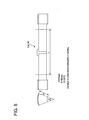
- Figure 4 (A) shows the results of fracture testing on the embodiment shown in the foregoing Figure 3.
- the joint welded according to the welding method of the present invention exhibited fracture 20 in base metal 10, thereby demonstrating that the joint had a strength equal to or greater than that of the base metal.
- the present method allows a reduction in pipe wall thickness of 10 to 15%, and about the same level of reduction in the amount of material used for fabrication.
- Figure 5 shows the dimensions of the creep fracture test samples used in the creep fracture tests, which were used to evaluate the high temperature brittle fracture status for joints welded according to the method of this invention.
- this invention makes it possible to reduce pipe wall thickness by 10-15%, and make similar reductions in the amount of material used.
- the present invention is further markedly effective with high strength ferrite type heat resistant steels, which are normally subject to dramatic strength reductions in the welding heat affected area. It allows their unique advantages, which are not seen in austenite type steels, to be effectively exploited.
Landscapes
- Engineering & Computer Science (AREA)
- Mechanical Engineering (AREA)
- Physics & Mathematics (AREA)
- Plasma & Fusion (AREA)
- Arc Welding In General (AREA)
- Butt Welding And Welding Of Specific Article (AREA)
Abstract
Description
Although a great deal of research has gone into the mechanism for this reduction and for improving the base metal component, the problem remains unresolved.
forming a fusion zone in the foregoing heat affected area by beginning a welding line at the toe of the groove and, prior to forming excess metal atop the weld, successively extending the line over the entire range of the heat affected area on the surface of the base metal, using multi-pass buildup over said extended area,
wherein,
the same level of creep strength as is inherent in the base metal can be achieved using a computation map, which is based upon the relationship between the groove width and the thickness of the base metal, to determine the surface area for the foregoing fusion extension.
wherein,
the foregoing fusion area over the heat affected area is formed by successively extending the welding line from the toe of the groove over the entire area of the heat affected area on the surface of the base metal, with said fusion successively absorbing the residual stress that was created in the heat affected area on the surface of the base metal, to create a multi-pass buildup thereupon, wherein the establishment of the extension surface area for the foregoing fusion extension to achieve the same creep strength as is inherent in the base metal may be determined by a computational map based upon the relationship between the groove width and the thickness of the base metal.
after completing the multi-pass buildup welding of the groove, a multi-layered weld cap that covers at least a part of the heat affected area is fused upon the surface of the base metal,
wherein,
the foregoing fusion area over the heat affected area is formed by successively extending the welding line from the toe of the groove over the entire area of the heat affected area on the surface of the base metal , with the foregoing fusion successively absorbs the residual stress that was created in the heat affected area on the surface of the base metal, to create a multi-pass buildup thereupon, and wherein,
the establishment of the extension surface area to achieve the same creep strength as is inherent in the base metal for the foregoing fusion extension may be determined by a computational map based upon the relationship between the groove width/and the thickness of the base metal.
the fusion area of the foregoing heat affected
| Base Metal | Commercial ASME SA-335 P91 large diameter thick walled pipe (diameter 350 × thickness 50) |
| Welding Materials | Commercial improved 9 CR copper TIG welding wire (diameter 1.2 mm) |
| Welding conditions: preheating temperature 150 degrees C | |
| Welding current: 90 - 300A | |
| Welding voltage: 9 - 14V | |
| Welding rate: 60 mm/minute | |
| Number of layers: 40 layers | |
| Heat treatment | SR stress relief annealing after welding for 12 hr. at 750 degrees C |


Claims (5)
- A welded joint in high strength, heat resistant steels having the joint groove filled with the multi-pass buildup welding, and subsequently covered with a multi-layered weld cap atop the weld face that fuses at least a part of the heat affected area, wherein said joint is characterized by the fusion area on said heat affected area being formed by shifting the welding line from the toe of the groove and extending it over the entire range of the heat affected area on the surface of the base metal in order to form a multi-layered weld cap that covers said extended area.
- A welded joint in high strength with the multi-pass buildup welding according to claim 1, wherein the surface area of said extension that is required to impart the same level of creep strength as is inherent in the base metal is based on the relationship between the groove width and the base metal thickness.
- A welded joint in high strength with the multi-pass buildup welding according to claim 1, wherein said upper multi-layered weld cap by the extension of the fusion area is formed by the multi-pass buildup which gradually absorbs the residual stress of the heat affected area on the surface of the base metal.
- A welding method for a welded joint in high strength, heat resistant steels having the joint groove filled with the multi - pass buildup welding, and subsequently covered with a multi-layered weld cap atop the weld face that fuses at least a part of the heat affected area, comprising the step of forming a fusion area in said heat affected area by beginning a welding line at the toe of the groove and, prior to forming excess metal atop the weld, successively extending the line over the entire range of the heat affected area on the surface of the base metal, forming multi-pass buildup over said extended area,
wherein the same level of creep strength as is inherent in the base metal can be achieved using a computation map, which is based upon the relationship between the groove width and the thickness of the base metal, to determine the surface area for said fusion extension. - A welding method for a welded joint in high strength ferrite heat resistant steels having the joint groove filled with the multi-pass buildup welding, and subsequently covered with a multi-layered weld cap atop the weld face that fuses at least a part of the heat affected area, comprising the step of forming a fusion zone in said heat affected area by beginning a welding line at the toe of the groove and, prior to forming excess metal atop the weld, successively extending the line over the entire range of the heat affected area on the surface of the base metal, using multi-pass buildup over said extended area,
wherein the same level of creep strength as is inherent in the base metal can be achieved using a computation map, which is based upon the relationship between the groove width and the thickness of the base metal, to determine the surface area for said fusion extension.
Applications Claiming Priority (2)
| Application Number | Priority Date | Filing Date | Title |
|---|---|---|---|
| JP2001137154 | 2001-05-08 | ||
| JP2001137154A JP4633959B2 (en) | 2001-05-08 | 2001-05-08 | Welded joint of high-strength heat-resistant steel and its welding method |
Publications (3)
| Publication Number | Publication Date |
|---|---|
| EP1256411A2 true EP1256411A2 (en) | 2002-11-13 |
| EP1256411A3 EP1256411A3 (en) | 2004-05-19 |
| EP1256411B1 EP1256411B1 (en) | 2007-10-10 |
Family
ID=18984303
Family Applications (1)
| Application Number | Title | Priority Date | Filing Date |
|---|---|---|---|
| EP02009889A Expired - Lifetime EP1256411B1 (en) | 2001-05-08 | 2002-05-02 | Welding method for a welded joint in high strength, ferrite type heat resistant steels |
Country Status (10)
| Country | Link |
|---|---|
| US (1) | US6919534B2 (en) |
| EP (1) | EP1256411B1 (en) |
| JP (1) | JP4633959B2 (en) |
| KR (1) | KR100516010B1 (en) |
| CN (1) | CN100488700C (en) |
| BR (1) | BR0201619A (en) |
| DE (1) | DE60222827T2 (en) |
| ES (1) | ES2294061T3 (en) |
| MX (1) | MXPA02004534A (en) |
| ZA (1) | ZA200203616B (en) |
Cited By (1)
| Publication number | Priority date | Publication date | Assignee | Title |
|---|---|---|---|---|
| WO2015004538A3 (en) * | 2013-06-28 | 2015-07-02 | Saudi Basic Industries Corporation | Multilayer repair of thick wall vessels |
Families Citing this family (19)
| Publication number | Priority date | Publication date | Assignee | Title |
|---|---|---|---|---|
| US8437444B2 (en) * | 2005-01-13 | 2013-05-07 | Nac International, Inc. | Apparatus and methods for achieving redundant confinement sealing of a spent nuclear fuel canister |
| CN100413629C (en) * | 2006-11-22 | 2008-08-27 | 山东大学 | Welding process of 800MPa high strength steel without preheating |
| KR100866631B1 (en) * | 2007-04-19 | 2008-11-04 | (주)일진에너지 | How to weld special metals |
| KR100973845B1 (en) * | 2008-02-04 | 2010-08-06 | 홍완식 | House bottom plate |
| KR101218961B1 (en) * | 2009-12-04 | 2013-01-04 | 신닛테츠스미킨 카부시키카이샤 | Butt-welded joint formed using high-energy-density beam |
| WO2011068155A1 (en) * | 2009-12-04 | 2011-06-09 | 新日本製鐵株式会社 | Butt welded joint of welded structure, and method for manufacturing same |
| DE102011055282A1 (en) * | 2011-07-26 | 2013-01-31 | Alstom Technology Ltd. | Method for welding thin-walled pipes by means of peak tempering welding |
| CN102950388A (en) * | 2011-08-23 | 2013-03-06 | 北京威斯顿亚太光电仪器有限公司 | Medical rigid tube endoscope resistant to high temperature and high pressure |
| DE102011054718B4 (en) * | 2011-10-21 | 2014-02-13 | Hitachi Power Europe Gmbh | Method for generating a voltage reduction in erected tube walls of a steam generator |
| CN102489842B (en) * | 2011-12-07 | 2013-05-22 | 鞍山锅炉厂有限公司 | Argon tungsten-arc welding process for pearlite heat-resistant steel pipe and austenitic heat-resistant steel pipe |
| EP2787167B1 (en) * | 2013-04-04 | 2018-12-26 | Ansaldo Energia IP UK Limited | Method for welding rotors for power generation |
| JP6730927B2 (en) * | 2014-01-24 | 2020-07-29 | エレクトリック パワー リサーチ インスチテュート インコーポレイテッド | Products for welded joints with step design |
| CN104014916B (en) * | 2014-06-06 | 2016-08-17 | 南通国电电站阀门有限公司 | F91 valve body and 10CrMo910 pipe arrangement different steel weld method |
| US10967946B1 (en) | 2014-12-17 | 2021-04-06 | Brunswick Corporation | Systems and methods for mounting a propulsion device with respect to a marine vessel |
| SG11201804642UA (en) * | 2016-01-29 | 2018-07-30 | Jfe Steel Corp | Welded joint and method for manufacturing same |
| JP7082541B2 (en) * | 2018-07-20 | 2022-06-08 | 三菱重工業株式会社 | Repair welding method |
| CN109783921B (en) * | 2019-01-07 | 2023-08-15 | 中国石油化工集团有限公司 | Heat affected zone evaluation method and device for oil and gas conveying pipeline and computer equipment |
| CN111645071B (en) * | 2020-05-21 | 2023-04-11 | 济南重工股份有限公司 | Robot welding control system and control method based on PLC |
| CN113399937A (en) * | 2021-05-14 | 2021-09-17 | 西安理工大学 | Copper/steel bimetal composite structural member combined with heat treatment process and preparation method thereof |
Family Cites Families (18)
| Publication number | Priority date | Publication date | Assignee | Title |
|---|---|---|---|---|
| US4196335A (en) * | 1976-03-26 | 1980-04-01 | Sumitomo Metal Industries, Ltd. | Submerged arc welding process |
| US4049186A (en) * | 1976-10-20 | 1977-09-20 | General Electric Company | Process for reducing stress corrosion in a weld by applying an overlay weld |
| US4187410A (en) * | 1977-03-10 | 1980-02-05 | Vsesojuzny Nauchno-Issledovatelsky, Proektno-Konstruktorsky i Tekhnologichesky Institut Elektrosvarochnogo Oborudova | Method of multi-pass narrow groove arc welding |
| JPS5431062A (en) * | 1977-08-12 | 1979-03-07 | Hitachi Ltd | Manufacture of structure superior in stress corrosion cracking resistivity |
| JPS55147495A (en) * | 1979-05-09 | 1980-11-17 | Hitachi Ltd | Butt welding method |
| JPS5623227A (en) * | 1979-08-01 | 1981-03-05 | Babcock Hitachi Kk | Fine graining method of crystal grain of heat affected zone of final weld layer |
| FR2478509A1 (en) * | 1980-03-20 | 1981-09-25 | Kobe Steel Ltd | Butt welding pipes by TIG hot wire process - controlled to produce thicker weld deposit having improved creep strength |
| JPS57202996A (en) * | 1981-06-05 | 1982-12-13 | Kawasaki Steel Corp | Highly basic burnt type flux for submerged arc welding excellent in slag separation in narrow groove |
| US4624402A (en) * | 1983-01-18 | 1986-11-25 | Nutech, Inc. | Method for applying an overlay weld for preventing and controlling stress corrosion cracking |
| JPS59159294A (en) * | 1983-02-28 | 1984-09-08 | Ishikawajima Harima Heavy Ind Co Ltd | Improvement of residual stress by build-up welding on outside circumferential surface of pipe |
| IT1225672B (en) * | 1988-07-22 | 1990-11-22 | Ansaldo Spa | SUPPORT GRID OF THE NUT OF A NUCLEAR REACTOR AND MANUFACTURING PROCEDURE OF THE SAME |
| US5156321A (en) * | 1990-08-28 | 1992-10-20 | Liburdi Engineering Limited | Powder metallurgy repair technique |
| US5258600A (en) * | 1992-03-31 | 1993-11-02 | Exxon Production Research Company | Process for welding thermally and/or mechanically treated metal conduits |
| JPH079147A (en) * | 1993-06-22 | 1995-01-13 | Nippon Steel Corp | Welding method of high-purity ferritic stainless steel plate |
| JP3362357B2 (en) * | 1993-08-24 | 2003-01-07 | 忠弘 大見 | Welded joints and welding methods |
| DE59407600D1 (en) * | 1994-01-29 | 1999-02-18 | Asea Brown Boveri | Process for joining metal parts by means of arc fusion welding |
| FR2742368B1 (en) * | 1995-12-18 | 1998-03-06 | Framatome Sa | METHOD OF CONNECTION BY HETEROGENEOUS WELDING END TO END OF TWO PARTS OF DIFFERENT NATURES AND USES |
| JP2000237869A (en) * | 1999-02-17 | 2000-09-05 | Ishikawajima Harima Heavy Ind Co Ltd | Pipe butt welding method |
-
2001
- 2001-05-08 JP JP2001137154A patent/JP4633959B2/en not_active Expired - Lifetime
-
2002
- 2002-05-02 ES ES02009889T patent/ES2294061T3/en not_active Expired - Lifetime
- 2002-05-02 DE DE60222827T patent/DE60222827T2/en not_active Expired - Lifetime
- 2002-05-02 EP EP02009889A patent/EP1256411B1/en not_active Expired - Lifetime
- 2002-05-07 KR KR10-2002-0025006A patent/KR100516010B1/en not_active Expired - Fee Related
- 2002-05-07 ZA ZA200203616A patent/ZA200203616B/en unknown
- 2002-05-07 MX MXPA02004534A patent/MXPA02004534A/en active IP Right Grant
- 2002-05-07 BR BR0201619-2A patent/BR0201619A/en not_active Application Discontinuation
- 2002-05-08 US US10/140,261 patent/US6919534B2/en not_active Expired - Lifetime
- 2002-05-08 CN CNB021401950A patent/CN100488700C/en not_active Expired - Fee Related
Cited By (1)
| Publication number | Priority date | Publication date | Assignee | Title |
|---|---|---|---|---|
| WO2015004538A3 (en) * | 2013-06-28 | 2015-07-02 | Saudi Basic Industries Corporation | Multilayer repair of thick wall vessels |
Also Published As
| Publication number | Publication date |
|---|---|
| ES2294061T3 (en) | 2008-04-01 |
| EP1256411B1 (en) | 2007-10-10 |
| JP2002331362A (en) | 2002-11-19 |
| DE60222827D1 (en) | 2007-11-22 |
| EP1256411A3 (en) | 2004-05-19 |
| US6919534B2 (en) | 2005-07-19 |
| KR20020085833A (en) | 2002-11-16 |
| KR100516010B1 (en) | 2005-09-26 |
| DE60222827T2 (en) | 2008-07-24 |
| JP4633959B2 (en) | 2011-02-16 |
| MXPA02004534A (en) | 2004-07-16 |
| BR0201619A (en) | 2003-03-11 |
| CN100488700C (en) | 2009-05-20 |
| CN1385278A (en) | 2002-12-18 |
| US20030038167A1 (en) | 2003-02-27 |
| ZA200203616B (en) | 2002-12-12 |
Similar Documents
| Publication | Publication Date | Title |
|---|---|---|
| US6919534B2 (en) | Welded joints in high strength, heat resistant steels, and a welding method therefor | |
| US6379821B2 (en) | Martensitic stainless steel welded pipe | |
| EP1418245A9 (en) | Long-life heat-resisting low alloy steel welded component and method of manufacturing the same | |
| EP0668120A1 (en) | Method of forming a weld joint of austenitic stainless steel | |
| CN109693072A (en) | 825/X70/825 double-sided composite board and production method thereof | |
| CA1267303A (en) | High toughness steel | |
| JP2000015447A (en) | Welding method for martensitic stainless steel | |
| JPH0787990B2 (en) | Submerged arc welding method for high strength Cr-Mo steel | |
| JPH09327721A (en) | Method for manufacturing martensitic stainless welded steel pipe with excellent weldability | |
| JP3215326B2 (en) | Welding material for overlaying journal part of high chromium content rotor, high chromium content rotor, and method of manufacturing the rotor | |
| JPS6317038B2 (en) | ||
| JPH0787989B2 (en) | Gas shield arc welding method for high strength Cr-Mo steel | |
| US3859082A (en) | Wrought austenitic alloy products | |
| JPS60238423A (en) | Improvement of corrosion resistance in weld zone of two-phase stainless steel | |
| JP7786650B1 (en) | TIG welding method | |
| KR19990013950A (en) | Welding rod made of nickel base alloy and nickel base alloy | |
| KR100376492B1 (en) | Method For Flux Cored Arc Welding 9%Ni Steel | |
| JP2001179484A (en) | Welded joint for steel structure and method of manufacturing the same | |
| Dove et al. | An austenitic stainless steel, resistant to high temperature creep and naphthenic acids attack in refinery environments | |
| JPS61144284A (en) | Production of clad material | |
| Libra | Welding 22Cr5Ni3Mo corrosion‐resistant dual‐phase steel | |
| JPH0314549B2 (en) | ||
| Slaughter et al. | Welding and brazing filler metals | |
| JPS6124118B2 (en) | ||
| JPS596743B2 (en) | Welding method |
Legal Events
| Date | Code | Title | Description |
|---|---|---|---|
| PUAI | Public reference made under article 153(3) epc to a published international application that has entered the european phase |
Free format text: ORIGINAL CODE: 0009012 |
|
| 17P | Request for examination filed |
Effective date: 20020502 |
|
| AK | Designated contracting states |
Kind code of ref document: A2 Designated state(s): AT BE CH CY DE DK ES FI FR GB GR IE IT LI LU MC NL PT SE TR |
|
| AX | Request for extension of the european patent |
Free format text: AL;LT;LV;MK;RO;SI |
|
| PUAL | Search report despatched |
Free format text: ORIGINAL CODE: 0009013 |
|
| AK | Designated contracting states |
Kind code of ref document: A3 Designated state(s): AT BE CH CY DE DK ES FI FR GB GR IE IT LI LU MC NL PT SE TR |
|
| AX | Request for extension of the european patent |
Extension state: AL LT LV MK RO SI |
|
| RIC1 | Information provided on ipc code assigned before grant |
Ipc: 7B 23K 31/02 B Ipc: 7B 23K 9/02 B Ipc: 7B 23K 9/04 B Ipc: 7B 23K 20/22 A |
|
| AKX | Designation fees paid |
Designated state(s): DE ES GB IT |
|
| 17Q | First examination report despatched |
Effective date: 20050701 |
|
| GRAP | Despatch of communication of intention to grant a patent |
Free format text: ORIGINAL CODE: EPIDOSNIGR1 |
|
| RTI1 | Title (correction) |
Free format text: WELDING METHOD FOR A WELDED JOINT IN HIGH STRENGTH, FERRITE TYPE HEAT RESISTANT STEELS |
|
| GRAS | Grant fee paid |
Free format text: ORIGINAL CODE: EPIDOSNIGR3 |
|
| GRAA | (expected) grant |
Free format text: ORIGINAL CODE: 0009210 |
|
| AK | Designated contracting states |
Kind code of ref document: B1 Designated state(s): DE ES GB IT |
|
| REG | Reference to a national code |
Ref country code: GB Ref legal event code: FG4D |
|
| REF | Corresponds to: |
Ref document number: 60222827 Country of ref document: DE Date of ref document: 20071122 Kind code of ref document: P |
|
| REG | Reference to a national code |
Ref country code: ES Ref legal event code: FG2A Ref document number: 2294061 Country of ref document: ES Kind code of ref document: T3 |
|
| PLBE | No opposition filed within time limit |
Free format text: ORIGINAL CODE: 0009261 |
|
| STAA | Information on the status of an ep patent application or granted ep patent |
Free format text: STATUS: NO OPPOSITION FILED WITHIN TIME LIMIT |
|
| 26N | No opposition filed |
Effective date: 20080711 |
|
| PGFP | Annual fee paid to national office [announced via postgrant information from national office to epo] |
Ref country code: DE Payment date: 20200422 Year of fee payment: 19 Ref country code: ES Payment date: 20200601 Year of fee payment: 19 |
|
| PGFP | Annual fee paid to national office [announced via postgrant information from national office to epo] |
Ref country code: GB Payment date: 20200422 Year of fee payment: 19 Ref country code: IT Payment date: 20200414 Year of fee payment: 19 |
|
| REG | Reference to a national code |
Ref country code: DE Ref legal event code: R119 Ref document number: 60222827 Country of ref document: DE |
|
| GBPC | Gb: european patent ceased through non-payment of renewal fee |
Effective date: 20210502 |
|
| PG25 | Lapsed in a contracting state [announced via postgrant information from national office to epo] |
Ref country code: GB Free format text: LAPSE BECAUSE OF NON-PAYMENT OF DUE FEES Effective date: 20210502 Ref country code: DE Free format text: LAPSE BECAUSE OF NON-PAYMENT OF DUE FEES Effective date: 20211201 |
|
| REG | Reference to a national code |
Ref country code: ES Ref legal event code: FD2A Effective date: 20220728 |
|
| PG25 | Lapsed in a contracting state [announced via postgrant information from national office to epo] |
Ref country code: ES Free format text: LAPSE BECAUSE OF NON-PAYMENT OF DUE FEES Effective date: 20210503 |
|
| PG25 | Lapsed in a contracting state [announced via postgrant information from national office to epo] |
Ref country code: IT Free format text: LAPSE BECAUSE OF NON-PAYMENT OF DUE FEES Effective date: 20200502 |
|
| PG25 | Lapsed in a contracting state [announced via postgrant information from national office to epo] |
Ref country code: IT Free format text: LAPSE BECAUSE OF NON-PAYMENT OF DUE FEES Effective date: 20210502 |