EP1418245A9 - Long-life heat-resisting low alloy steel welded component and method of manufacturing the same - Google Patents

Long-life heat-resisting low alloy steel welded component and method of manufacturing the same Download PDF

Info

Publication number
EP1418245A9
EP1418245A9 EP03025611A EP03025611A EP1418245A9 EP 1418245 A9 EP1418245 A9 EP 1418245A9 EP 03025611 A EP03025611 A EP 03025611A EP 03025611 A EP03025611 A EP 03025611A EP 1418245 A9 EP1418245 A9 EP 1418245A9
Authority
EP
European Patent Office
Prior art keywords
base metal
heat
welding
hot working
alloy steel
Prior art date
Legal status (The legal status is an assumption and is not a legal conclusion. Google has not performed a legal analysis and makes no representation as to the accuracy of the status listed.)
Withdrawn
Application number
EP03025611A
Other languages
German (de)
French (fr)
Other versions
EP1418245A3 (en
EP1418245A2 (en
Inventor
Hideshi Tezuka
Current Assignee (The listed assignees may be inaccurate. Google has not performed a legal analysis and makes no representation or warranty as to the accuracy of the list.)
Tokyo Electric Power Company Holdings Inc
Original Assignee
Tokyo Electric Power Co Inc
Priority date (The priority date is an assumption and is not a legal conclusion. Google has not performed a legal analysis and makes no representation as to the accuracy of the date listed.)
Filing date
Publication date
Application filed by Tokyo Electric Power Co Inc filed Critical Tokyo Electric Power Co Inc
Publication of EP1418245A2 publication Critical patent/EP1418245A2/en
Publication of EP1418245A9 publication Critical patent/EP1418245A9/en
Publication of EP1418245A3 publication Critical patent/EP1418245A3/en
Withdrawn legal-status Critical Current

Links

Images

Classifications

    • CCHEMISTRY; METALLURGY
    • C22METALLURGY; FERROUS OR NON-FERROUS ALLOYS; TREATMENT OF ALLOYS OR NON-FERROUS METALS
    • C22CALLOYS
    • C22C38/00Ferrous alloys, e.g. steel alloys
    • C22C38/18Ferrous alloys, e.g. steel alloys containing chromium
    • C22C38/22Ferrous alloys, e.g. steel alloys containing chromium with molybdenum or tungsten
    • CCHEMISTRY; METALLURGY
    • C21METALLURGY OF IRON
    • C21DMODIFYING THE PHYSICAL STRUCTURE OF FERROUS METALS; GENERAL DEVICES FOR HEAT TREATMENT OF FERROUS OR NON-FERROUS METALS OR ALLOYS; MAKING METAL MALLEABLE, e.g. BY DECARBURISATION OR TEMPERING
    • C21D1/00General methods or devices for heat treatment, e.g. annealing, hardening, quenching or tempering
    • C21D1/26Methods of annealing
    • C21D1/28Normalising
    • CCHEMISTRY; METALLURGY
    • C21METALLURGY OF IRON
    • C21DMODIFYING THE PHYSICAL STRUCTURE OF FERROUS METALS; GENERAL DEVICES FOR HEAT TREATMENT OF FERROUS OR NON-FERROUS METALS OR ALLOYS; MAKING METAL MALLEABLE, e.g. BY DECARBURISATION OR TEMPERING
    • C21D8/00Modifying the physical properties by deformation combined with, or followed by, heat treatment
    • C21D8/02Modifying the physical properties by deformation combined with, or followed by, heat treatment during manufacturing of plates or strips
    • C21D8/0205Modifying the physical properties by deformation combined with, or followed by, heat treatment during manufacturing of plates or strips of ferrous alloys

Definitions

  • the present invention relates to a heat-resisting low alloy steel welded component of a structure used under a high-temperature and high-pressure atmosphere such as a thermal power plant or petrochemical plant.
  • the invention also relates to a method of manufacturing a welded component of heat-resisting steel used in facilities that use in many occasions a thick structure of a ferritic heat-resisting low alloy steel.
  • boilers are employed under a higher temperature and pressure, and their capacities are increasing.
  • thermal power plants that can operate under a steam pressure of 316 kg/cm 2 and a steam temperature of 566°C and have a large capacity that is equivalent to a 700,000 to 1,000,000 kW-class plant are constructed at present.
  • the steel pipe material used for such a boiler is mainly divided into carbon steel or low-alloy steel, and high alloy steel, a typical example of which is austenitic stainless steel. These materials are carefully selected in accordance with the temperature and pressure of the section where the material is used. For example, for a hot reheat steam pipe or main steam pipe in which the temperature becomes 450°C or higher when in use, Mo steel or Cr-Mo steel, which has an excellent anti-oxidation property and heat resisting property, is used.
  • a thick pipe made of Cr-Mo low alloy steel is employed since these pipes have to stand a high internal pressure and temperature.
  • ferritic low alloy heat-resisting steel that is defined by JIS G 3458 (1988) is used for the pipes.
  • a weld with a high joint efficiency is used.
  • various creep damages are created at the weld zone.
  • the type 4 damage which is created in a fine grained region of the HAZ, causes to significantly shorten the lifetime of the weld zone of the pipe, and therefore this type of damage is perceived as a problem in many countries.
  • the type 4 damage is discussed in, for example, a non-patent document, "Review of Type IV Cracking" written by F.V. Ellis and R. Viswanathan (ASME PVP vol. 380, July 1998).
  • a heat-resisting steel pipe is manufactured in a procedure shown in FIG. 8B. That is, a steel lumber is carried out an acceptance test. The tested steel lumber is marked and then cut into steel pieces (S11). Then, steel pieces are bent by hot working (S12). Another marking is carried out on the pieces and then cut (S13). The cut pieces are subjected to a heat treatment (S14). Subsequently, the treated pieces are subjected to a mechanical edge preparation (15). The prepared pieces are aligned edges each other (S16) and then welded together by a submerged arc welding method (S17).
  • the present invention has been proposed as a solution to the above-described drawback of the conventional technique, and the object thereof is to provide a long-life heat-resisting low alloy steel welded component that does not easily cause a creep damage in a heat-affected zone and a method of manufacturing the same.
  • a method of manufacturing a long-life heat-resisting low alloy steel welded component including the steps of subjecting a base metal containing, at % by weight, C: 0.15% or less, Si: 0.5% or less, Mn: 0.3 to 0.8%, Cr: 1.9 to 2.6%, Mo: 0.87 to 1.20%, and a balance of iron and unavoidable impurities, to a hot working (S3), to a heat treatment (S5), and then to a welding (S8), the method being characterized by normalizing the base metal once or more times before the welding (S8) in addition to the hot working (S3).
  • the method of the present invention can be applied to a base metal containing, at % by weight, Mn: 0.3 to 0.6% and Mo: 0.87 to 1.13%. In this case, it is preferable that the normalizing of the base metal should be carried out at least twice.
  • a method of manufacturing a long-life heat-resisting low alloy steel welded component including the steps of subjecting a base metal containing, at % by weight, C: 0.04% to 0.10%, Si: 0.5% or less, Mn: 0.1 to 0.6%, Cr: 1.9 to 2.6%, Mo: 0.05 to 0.3%, V: 0.20 to 0.30%, Nb: 0.02 to 0.08%, W: 1.45 to 1.75%, B: 0.0005 to 0.006% and a balance of iron and unavoidable impurities, to a hot working, to a heat treatment, and then to a welding, the method being characterized by normalizing the base metal once or more times before the welding in addition to the hot working.
  • a method of manufacturing a long-life heat-resisting low alloy steel welded component including the steps of subjecting a base metal containing, at % by weight, C: 0.2% or less, Si: 1.0% or less, Mn: 0.3 to 0.9%, Cr: 0.3 to 1.5%, Mo: 0.4 to 0.7%, and a balance of iron and unavoidable impurities, to a hot working, to a heat treatment, and then to a welding, the method being characterized by normalizing the base metal once or more times before the welding in addition to the hot working.
  • the method of the present invention can be applied to a base metal containing, at % by weight, Mn: 0.3 to 0.6%, Cr: 0.5 to 1.5% and Mo: 0.40 to 0.65%.
  • the method of the present invention can be applied to the base metal further containing, at % by weight, V: 0.22 to 0.50%.
  • the method of the present invention can be applied to a base metal that has been subjected to annealing or normalizing and tempering.
  • the method of the present invention should be carried out by subjecting the base metal to the normalizing and then to the hot working in a normalizing temperature range.
  • the long-life heat-resisting low alloy steel welded component according to the present invention can be manufactured by the above-described methods.
  • the welded component of the present invention can be applied to at least one of longitudinal joint and circumferential joint of pipes, vessel, valve casing and branch pipes that are used under a high-temperature and high-pressure steam atmosphere at a temperature of 450°C or higher.
  • the form of the base metal may be a plate, pipe, forging and casting.
  • the inventors of the present invention carried out intensive studies on creep damages of type 4, and discover the following facts.
  • the present invention has been achieved based on these findings.
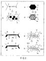
  • FIG. 2 The mechanism of occurrence of creep damages of type 4 is schematically illustrated in FIG. 2. Further, the results of observation of samples extracted from a site where damages of type 4 were created under a transmission electron microscope (TEM) or scanning electron microscope (SEM) are shown in the photographs of FIGS. 3 to 7.
  • TEM transmission electron microscope
  • SEM scanning electron microscope
  • type 4 crack occurs on the base metal side of the HAZ.
  • the present invention aims to reduce the amount of coarse carbides, which cause to damages of type 4, remaining in former austenite (y) grain boundaries of a welded component (base metal).
  • the creep lifetime of the weld zone of the heat-resisting steel can be significantly improved. More specifically, before the base metal is welded, it is subjected to normalizing once or more times, thereby reducing the amount of coarse carbides.
  • a steel lumber 21 is carried out an acceptance test (S1).
  • the steel lumber 21 is, as defined, for example, by JIS G 3458, either a material that has been subjected to normalizing and tempering once (NT material) or a material that has been subjected to annealing once (annealed material).
  • the steel lumber 21 is marked and then cut into steel pieces 22.
  • the steel pieces 22 are subjected normalizing at a predetermined temperature (S2). Subsequently, they are bent by hot working with use of a recess type mold and a projection type mold at a temperature within a range of 900 to 1,000°C into bent steel pieces 22a (S3).
  • the hot press bending is not carried out to follow the normalizing, the steel pieces are heated up to a temperature within a range of 900 to 1,000°C, and then subjected to hot press bending.
  • bent steel pieces 22a are marked and then cut (S4).
  • the cut pieces are subjected to a heat treatment within a predetermined temperature range in a furnace 25 (S5).
  • two or more bent steel pieces are placed on an edge rest 26 and then subjected to a mechanical edge preparation with a cutting edge 27.
  • the bent steel pieces 22a are aligned their edges each other (S7) and they are welded together by hands from the first to second or third layers. Then, they are subjected to a full-automatic submerged arc welding by 5 to 50 passes, and thus a linear joint steel pipe having a longitudinal joint is prepared (S8).
  • high temperature used in this specification indicates mainly a temperature in a range of 450 to 650°C unless the temperature is particularly specified.
  • JIS G 4109 SCMV 3 Div 1 ASTM A 387/A 387M Gr.11, Cl.1 K11789 and Gr.11, Cl.2 K11789; JIS G 4109 SCMV 3 Div 2
  • JIS G 4109 SCMV 5 Div 1 ASTM A 387/A 387M Gr.21, Cl.1, Gr.21L, Cl.1 and Gr.21, Cl.2 K31545; JIS G 4109 SCMV 5 Div 2
  • JIS G 4109 SCMV 6 Div 1 ASTM A 387/A 387M Gr.5, Cl.1 and Gr.5, Cl.2 K41545 S50100 and S50200; JIS G 4109 SCMV 6 Div 2
  • KA-SCMV4J1 specified by Code for Thermal Power Generation Facilities (to be abbreviated as "CTPGF” hereinafter) of JSME standard can be also used.
  • CPGF Code for Thermal Power Generation Facilities
  • JIS G 4110 SCMQ4E, SCMQ4V and SCMQ5V can be employed as well.
  • JIS G 3203 SFVA F 11 A ASTM A 182/A 182M F 11, Cl 2 K11572; ASTM A 336/A 336M F11, Cl2 and F11, Cl3 K11572; JIS G 3203 SFVA F 11 B
  • JIS G 3203 SFVA F 22 A ASTM A 182/A 182M F 22, Cl 1 K21590; ASTM A 336/A 336M F22, Cl 1 K21590; EN 10222-2 11CrMo9-10 1.7383; ISO 9327-2 13CrMo9-10; ASTM A 182/A 182M F 22, Cl 3 K21590; ASTM A 336/A 336M F22, Cl3 K21590; JIS G 3203 SFVA F 22 B
  • JIS G 3203 SFVA F 21 A ASTM A 336/A 336M F21, Cl1 K31545; ASTM A 182/A 182M F 21 K31545; ASTM A 336/A 336M F21, Cl3 K31545; JIS G 3203 SFVA F 21 B
  • JIS G 3206 SFVCM F3V JIS G 3206 SFVCM F3V; ASTM A 182/A 182M F 3V K31830; ASTM A 336/A 336M F3V; ASTM A 508/A 508M 3V K31830; ASTM A 541/A 541M 3V K31830
  • CTPGF KA-SFVAF22AJ1 of JSME standard can be employed as well. (Extracted from Reference Document 2 ⁇ TABLE II-1-1 Notes> 18.)
  • a base metal having the above-specified composition is subjected to hot working and heat treatment, and then it is welded to prepare a component.
  • the normalizing process is carried out once or more as a separate step from the hot working.
  • Normalizing is carried out for a necessary number of times (once or more) so as to sufficiently,reduce the amount of coarse carbides present in former austenite grain boundaries in steel, that is, to have the carbides solid-dissolved and diffused into the matrix.
  • the number of times that the normalizing carried out should preferably be once or twice; however it may be varied widely depending on the thickness and the chemical compositions of the material.
  • the normalizing should preferably performed two or three or more times.
  • a ferritic heat-resisting low-alloy steel that can be used in the present invention is a normalized and tempered material (NT material), which is, when manufacturing its base metal (for example, a lumber 21 in FIG. 8A), heated up to a complete austenite region and then tempered.
  • NT material normalized and tempered material
  • heating carried out during the manufacture of the base metal is regarded substantially as normalizing. Therefore, in the case of such a base metal, if the normalizing is carried out at least once before the welding as a separate step from the hot working, it is practically assumed that a total of two or more times of normalizing are carried out. Thereby, the amount of coarse carbides can be reduced.
  • the normalizing includes the following procedures. That is, a base metal is heated to an appropriate normalizing temperature of point Ac3 or Ac1 or higher (for example, Ac3 + 50°C), and maintained at the temperature for a certain period of time. Then, the base metal is cooled down in the atmosphere. Alternatively, the base metal is cooled down to a temperature just above the Ar' point and maintained at the temperature until the completion of the isothermal transformation, and then it is air-cooled. In the normalizing, if the maintained temperature is excessively high, it is possible that the ⁇ grains become coarse more than necessary, whereas if the maintained temperature is excessively low, coarse carbides may not be sufficiently solid-dissolved.
  • an appropriate normalizing temperature of point Ac3 or Ac1 or higher for example, Ac3 + 50°C
  • the maintained time period at the normalizing temperature is excessively long, it is possible that the ⁇ grains become coarse more than necessary, thereby lowering the strength of the base metal.
  • the maintained normalizing temperature can be set to 920 to 930°C in the case of, for example, STPA 24.
  • the time period maintained at the normalizing temperature can be set to 0.5 to 1 hour in the case of, for example, STPA 24.
  • the appropriate maintaining temperature and maintaining time of the normalizing temperature vary depending on the type of steel employed. Therefore, it is preferable that the normalizing process should be carried out in accordance with the specification of the steel type in each case.
  • the temperature when carrying out the normalizing, the temperature may be maintained isothermally or the heating carried out within the above temperature range may be maintained within the above time range.
  • the normalizing of a base metal may be carried out at any timing if it is before the welding. However, when the normalizing process is carried out after the hot working, some dimensional error may occur due to thermal strain, and therefore it is preferable that the normalizing should be carried out before the hot working.
  • the hot working are press forming, rolling and bending.
  • the heating temperature, pressure and the like are not particularly limited, but it is preferable that the hot press bending should be carried out at a temperature within a range of 900 to 1,000°C continuously after the normalizing process.
  • the material should be heated to a temperature within a range of 900 to 1,000°C, and then the hot press bending should be carried out. It should be noted that if the hot working is carried out continuously after the normalizing process, the step of re-heating the material can be omitted, and therefore it is more efficient and thus more preferable.
  • the manufacturing method of the present invention can be applied to a welded steel pipe as well as a seamless steel pipe.
  • the hot working includes, for example, a step of hot pressing a hoop iron into a desired shape.
  • the material is subjected to normalizing and to hot working (press bending) first, and then the material is marked and cut. After that, the material is tempered to a temperature within a range of 700 to 750°C.
  • the material is subjected to normalizing and to hot working (press bending) at a temperature within a range of 850 to 1100°C first, and then the material is marked and cut. After that, the material is annealed by air-cooling, or by a liquid cooling method (such as oil quench hardening) if the material is thick, from a temperature within a range of 950 to 980°C. Subsequently, the material is tempered by maintaining the temperature within a range of 690 to 730°C for 30 minutes.
  • a liquid cooling method such as oil quench hardening
  • the present invention can be applied not only to longitudinal joint or circumferential joint of a longitudinal joint steel pipe as shown in FIG. 8, but also to circumferential joint of, for example, a spiral joint steel pipe or seamless steel pipe. Further, the present invention is applicable to longitudinal (seam) welding and circumferential welding carried out to prepare a steel pipe, but also to any of a pipe-to-end plate welding and pipe welding for boilers and heat exchanger.
  • the present invention can be applied to a heat-resisting low-alloy steel pipe used to make a large-diameter pipe employed in a thermal power plant or petrochemical plant.
  • a large-diameter pipe When such a large-diameter pipe is used in a situation where a high-temperature and high-pressure steam flows in the pipe, it may be exposed to an environment of a temperature of 450 to 600°C and a high pressure, in general cases.
  • a thermal power plant it may be exposed to an environment of a temperature of 538 to 566°C and a pressure of 169 to 316 kg/cm 2 . Therefore, pipes having a thickness of 25 to 150 mm are used.
  • the present invention can be effectively applied because it can reduce the amount of coarse carbides, which are origins of such creep damages, present along former austenite grain boundaries in steel, and thereby suppress the formation of a plate-like agglomeration region.
  • ASTM A387 Gr. D (which is equivalent to ASTM A387/A 387M 22) corresponding to STPA 24 defined by JIS was prepared.
  • the sample steel was subjected to hot press bending at a temperature of 900 to 930°C, and then marked and cut.
  • the cut pieces were subjected to tempering for 4 hours at a temperature of 700 to 730°C.
  • the pieces were subjected to mechanical edge preparation, and they were aligned their edges each other.
  • the outer side and inner side of the bent site were welded by submerged arc welding. In this manner, a 90° -elbow plate bent longitudinal seam steel pipe having an outer diameter of 508 mm and a thickness of 106 mm was manufactured.
  • the obtained steel pipe was used as a main steam pipe of a thermal power plant for about 145,000 hours to have it aged.
  • the aging conditions are the maximum pressure of 177.5 kgf/cm 2 and the maximum temperature of 575°C and the average temperature of 566°C.
  • the after-use, i.e. damaged, pipe was heated at a temperature of 1,000°C for 0.5 hours and then subjected to hot press to make the material into a plate shape. Then, the material was air-cooled and got a refreshed material (, which is the first substantial normalizing) (S3).
  • Two of such plate-like refreshed materials were prepared, and they were normalized at a temperature of 900°C for 2 hours and air-cooled (, which is the second substantial normalizing) (S2). After that, the materials were tempered at a temperature of 750°C for 2 hours and air-cooled (S5). After that, a pair of these plate materials were mechanically beveled to form edges (S6). Then, they were aligned their edges each other (S7), and welded together by submerged arc welding. In this manner, a sample weld having a thickness of 98 mm was manufactured (S8).
  • the obtained sample weld was aged by applying a fixed load of 400 kg/mm 2 onto a test piece with use of the method defined by JIS Z 2271 (1993).
  • the test piece was obtained from a depth about two fifth of the thickness from the outer surface as it had the HAZ fine grained region in the middle of the gauge.
  • the aging conditions are a temperature of 680°C and the test was continued until the piece was ruptured.
  • the rupture time of the test piece was about 220 hours. When converted under the actual use conditions, the rupture time is about 240,000 hours.
  • a simulation test was carried out until the test piece was ruptured in a similar manner to that of Example 1 except that the aging temperature was set to 670°C.
  • the rupture time of the test piece was about 380 hours. When converted under the actual use conditions, the rupture time is about 240,000 hours. Then, the test piece was observed as to whether a type 4 damage has occurred or not. The result was as indicated in TABLE 2.
  • Example 2 A simulation test was carried out until the test piece was ruptured in a similar manner to that of Example 1 except that the aging temperature was set to 650°C. The rupture time of the test piece was about 1,100 hours. Then, the test piece was observed as to whether a type 4 damage has occurred or not. The result was as indicated in TABLE 2.
  • Example 2 A simulation test was carried out in a similar manner to that of Example 1 except that the aging temperature was set to 566°C. Then, the test piece (, which was not ruptured,) was observed as to whether a type 4 damage has occurred or not. In this reference example, the test was aborted after 10,000 hours.
  • FIG. 9 is a TEM photograph showing the carbide structures under a magnification of about 500 times.
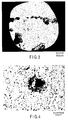
  • Example 2 In a similar manner to that of Example 1, a test piece (, which was not normalized,) was obtained from the HAZ fine grained region of the inner side of 90° -steel pipe elbow , which was used for about 188,000 hours as a main steam pipe of a thermal power plant. The actual used conditions of this example was substantially similar to the used condition of Example 1. Then, the piece was observed as to whether a type 4 damage has occurred or not. Subsequently, as in a similar manner to that of Example 3, the carbide structures of the sample were observed. The extraction replica (test piece) was taken at a depth about two thirds of the thickness from the outer surface. The results of the observation were as shown in FIG. 3 and TABLE 2.
  • the high-density agglomerated carbides can be suppressed as compared to the conventional welded component, thereby making it possible to reduce the type 4 damages.
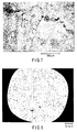
  • Example 3 a type 4 damage was observed; however, the rupture of the test piece was not directly caused by the type 4 damage. It is understood that the type 4 damage can be suppressed significantly in Example 3, thereby the rupture occurred in the portion other than the HAZ fine grained region. This is because, as compared to Comparative Example 1, the amount of high-density agglomerated carbides was remarkably less in Example 3.
  • the base metal was normalized once as a separate step from the hot working before the welding as in the present invention.
  • the type 4 damage was not observed even though it was aged at substantially an equal temperature and load to the actual use conditions.
  • Example 3 indicates a slight reticular carbide agglomeration has been created in a lower right section of the photograph.
  • Example 3 a few high-density agglomerated carbides were present as indicated in TABLE 2 but plate-like carbides was not observed.
  • another normalizing should be carried out, that is, a total of twice of normalizing should be carried out in addition to the hot working that serves also as refreshing. In this manner, a welded component having better properties with even less high-density agglomerated carbides can be created.
  • Comparative Example 1 By contrast, in Comparative Example 1, not only spherical carbides but also plate-like carbide agglomeration regions (dark portion in FIG. 3) were present in a wide range of the sample.
  • the identification of precipitates was carried out by an energy dispersion X-ray analysis.
  • (Mo, Fe) 6 C, (Cr, Fe) 23 C 6 and the like were defined, which suggested that the plate-like agglomeration of carbides occurs more easily in a steel type containing a great amount of Mo and Cr, as compared to a steel type containing low contents of these.
  • the present invention it is possible to provide a low-alloy steel welded component that does not easily have a plate-like agglomeration region of carbides even if it is exposed to multiple thermal cycles by submerged arc weldings, and it is used under conditions where a stress created by high internal pressure is applied thereon at a high temperature. Therefore, a long-life low-alloy steel welded component that does not easily create type 4 creep damages, which are caused by a plate-like carbide agglomeration region, can be obtained.
  • the present invention it is possible to provide a long-life low-alloy steel welded component that can be applied to a wide usage in facilities that employs a great number of thick pipes made of ferritic heat-resisting steel. Further, the welded component of the present invention does not easily create creep damages in a heat affected zone even if the submerged arc welding is used.

Landscapes

  • Chemical & Material Sciences (AREA)
  • Engineering & Computer Science (AREA)
  • Materials Engineering (AREA)
  • Mechanical Engineering (AREA)
  • Metallurgy (AREA)
  • Organic Chemistry (AREA)
  • Physics & Mathematics (AREA)
  • Thermal Sciences (AREA)
  • Crystallography & Structural Chemistry (AREA)
  • Heat Treatment Of Articles (AREA)
  • Arc Welding In General (AREA)
  • Heat Treatment Of Steel (AREA)

Abstract

The method of manufacturing a long-life heat-resisting low alloy steel welded component, with which creep damages do not easily occur in the heat affected zone. The manufacturing method includes the steps of subjecting a base metal containing, at % by weight, C: 0.15% or less, Si: 0.5% or less, Mn: 0.3 to 0.8%, Cr: 1.9 to 2.6%, Mo: 0.87 to 1.20%, and a balance of iron and unavoidable impurities, to a hot working (S3), to a heat treatment (S5), and then to a welding (S8). In this method the base metal is normalized (S2) once or more times before the welding (S8) in addition to the hot working (S3).

Description

The present invention relates to a heat-resisting low alloy steel welded component of a structure used under a high-temperature and high-pressure atmosphere such as a thermal power plant or petrochemical plant. The invention also relates to a method of manufacturing a welded component of heat-resisting steel used in facilities that use in many occasions a thick structure of a ferritic heat-resisting low alloy steel.
Recently, boilers are employed under a higher temperature and pressure, and their capacities are increasing. With this development, thermal power plants that can operate under a steam pressure of 316 kg/cm2 and a steam temperature of 566°C and have a large capacity that is equivalent to a 700,000 to 1,000,000 kW-class plant are constructed at present. The steel pipe material used for such a boiler is mainly divided into carbon steel or low-alloy steel, and high alloy steel, a typical example of which is austenitic stainless steel. These materials are carefully selected in accordance with the temperature and pressure of the section where the material is used. For example, for a hot reheat steam pipe or main steam pipe in which the temperature becomes 450°C or higher when in use, Mo steel or Cr-Mo steel, which has an excellent anti-oxidation property and heat resisting property, is used.
At present, for a large-diameter pipe such as a main steam pipe or hot reheat steam pipe that connects a boiler and a turbine, a thick pipe made of Cr-Mo low alloy steel is employed since these pipes have to stand a high internal pressure and temperature. In particular, in the thermal power plants in which a high-temperature and high-pressure steam is generated, such ferritic low alloy heat-resisting steel that is defined by JIS G 3458 (1988) is used for the pipes.
In welding of a steam pipe, a weld with a high joint efficiency is used. When such a steam pipe is used continuously under a high temperature and high pressure for a long period of time, various creep damages are created at the weld zone. There are four types of the creep damages as shown in FIG. 1. More specifically, there are a damage of type 1 created in a weld metal (deposit) 3, a damage of type 2 created in a section from a weld metal 3 to a heat-affected zone (HAZ) 2, a damage of type 3 created from a weld metal side of the HAZ 2, and a damage of type 4 created in a base metal 1 side of the HAZ 2. In particular, of these, the type 4 damage, which is created in a fine grained region of the HAZ, causes to significantly shorten the lifetime of the weld zone of the pipe, and therefore this type of damage is perceived as a problem in many countries. The type 4 damage is discussed in, for example, a non-patent document, "Review of Type IV Cracking" written by F.V. Ellis and R. Viswanathan (ASME PVP vol. 380, July 1998).
At present, a heat-resisting steel pipe is manufactured in a procedure shown in FIG. 8B. That is, a steel lumber is carried out an acceptance test. The tested steel lumber is marked and then cut into steel pieces (S11). Then, steel pieces are bent by hot working (S12). Another marking is carried out on the pieces and then cut (S13). The cut pieces are subjected to a heat treatment (S14). Subsequently, the treated pieces are subjected to a mechanical edge preparation (15). The prepared pieces are aligned edges each other (S16) and then welded together by a submerged arc welding method (S17).
When manufacturing a heat-resisting steel pipe by processing ferritic low alloy steel with the above-described procedure, it is difficult to avoid the occurrence of a creep damage in the HAZ. Especially, in the manufacture of a thick steel pipe having a thickness of 25 to 150 mm, the submerged arc welding is carried out for 5 to 50 layers. Therefore, the base metal situated near a weld zone is exposed to multiple heat cycles, in which quick heating and quick cooling are repeatedly carried out. For this reason, the grains become finer and finer in the HAZ. Further, in the case where, for example, such heat-resisting steel pipes are used to build a large-diameter pipe for a thermal power plant, these heat-resisting steel pipes are exposed to a high-temperature and high-pressure environment such as a temperature of 538 to 566°C and a pressure of 169 to 316 kg/cm2 due to the steam flowing through the large-diameter pipe. Further, a stress of 4 kg/mm2 load on the pipe in its circumferential direction. Therefore, in the HAZ fine grained region, a creep damage of the type 4 easily occurs, thereby shortening the lifetime of the component. The damaged section must be repaired, or if the damage is too severe to repair, the pipe itself must be replaced, costing a great amount of expense.
The present invention has been proposed as a solution to the above-described drawback of the conventional technique, and the object thereof is to provide a long-life heat-resisting low alloy steel welded component that does not easily cause a creep damage in a heat-affected zone and a method of manufacturing the same.
According to an aspect of the present invention, there is provided a method of manufacturing a long-life heat-resisting low alloy steel welded component including the steps of subjecting a base metal containing, at % by weight, C: 0.15% or less, Si: 0.5% or less, Mn: 0.3 to 0.8%, Cr: 1.9 to 2.6%, Mo: 0.87 to 1.20%, and a balance of iron and unavoidable impurities, to a hot working (S3), to a heat treatment (S5), and then to a welding (S8), the method being characterized by normalizing the base metal once or more times before the welding (S8) in addition to the hot working (S3).
The method of the present invention can be applied to a base metal containing, at % by weight, Mn: 0.3 to 0.6% and Mo: 0.87 to 1.13%. In this case, it is preferable that the normalizing of the base metal should be carried out at least twice.
According to another aspect of the present invention, there is provided a method of manufacturing a long-life heat-resisting low alloy steel welded component including the steps of subjecting a base metal containing, at % by weight, C: 0.04% to 0.10%, Si: 0.5% or less, Mn: 0.1 to 0.6%, Cr: 1.9 to 2.6%, Mo: 0.05 to 0.3%, V: 0.20 to 0.30%, Nb: 0.02 to 0.08%, W: 1.45 to 1.75%, B: 0.0005 to 0.006% and a balance of iron and unavoidable impurities, to a hot working, to a heat treatment, and then to a welding, the method being characterized by normalizing the base metal once or more times before the welding in addition to the hot working.
According to still another aspect of the present invention, there is provided a method of manufacturing a long-life heat-resisting low alloy steel welded component including the steps of subjecting a base metal containing, at % by weight, C: 0.2% or less, Si: 1.0% or less, Mn: 0.3 to 0.9%, Cr: 0.3 to 1.5%, Mo: 0.4 to 0.7%, and a balance of iron and unavoidable impurities, to a hot working, to a heat treatment, and then to a welding, the method being characterized by normalizing the base metal once or more times before the welding in addition to the hot working.
The method of the present invention can be applied to a base metal containing, at % by weight, Mn: 0.3 to 0.6%, Cr: 0.5 to 1.5% and Mo: 0.40 to 0.65%.
The method of the present invention can be applied to the base metal further containing, at % by weight, V: 0.22 to 0.50%.
The method of the present invention can be applied to a base metal that has been subjected to annealing or normalizing and tempering.
It is preferable that the method of the present invention should be carried out by subjecting the base metal to the normalizing and then to the hot working in a normalizing temperature range.
The long-life heat-resisting low alloy steel welded component according to the present invention can be manufactured by the above-described methods.
The welded component of the present invention can be applied to at least one of longitudinal joint and circumferential joint of pipes, vessel, valve casing and branch pipes that are used under a high-temperature and high-pressure steam atmosphere at a temperature of 450°C or higher.
Further, the form of the base metal may be a plate, pipe, forging and casting.
The inventors of the present invention carried out intensive studies on creep damages of type 4, and discover the following facts. The present invention has been achieved based on these findings.
The mechanism of occurrence of creep damages of type 4 is schematically illustrated in FIG. 2. Further, the results of observation of samples extracted from a site where damages of type 4 were created under a transmission electron microscope (TEM) or scanning electron microscope (SEM) are shown in the photographs of FIGS. 3 to 7.
  • (I) At an former austenite (γ) grain boundary 11 of a to-be-welded material, coarse carbide 12 resides as shown at (a) in FIG. 2. Note that there are ferrite grains (not shown at (a) in FIG. 2) within the former austenite grains. As the material is exposed to heat cycles during welding, the reduction of size of bainite grains 13, 14 is promoted and at the same time, coarse carbide 12 is decomposed and solid-dissolved into specific bainite 14. Thus, bainite fine grains 14 having an extremely dense precipitation of carbide are arranged along the former austenite grain boundary 11 as shown at (b) in FIG. 2. Particularly, in the case of jointing thick steel pipes, the submerged arc welding with a large amount of heat input; is employed and the pipes are exposed to multiple heat cycles repeated in 5 to 50 times. Therefore, the bainite texture 13, 14 located close to the weld zone is decomposed into finer grains due to quick heating and quick cooling and thus high-carbide bainite fine grains 14 are formed along the grain boundary 11.
  • (II) Next, an enlarged schematic view of a bainite fine grain 14 shown at (b) in FIG. 2 is illustrated at (c) in FIG. 2. Here, due to the heat treatment carried out after the welding and also the actual use under a high temperature and high pressure, coarse carbides 16 are re-precipitated along a grain boundary 15 as well as within a grain 14a of bainite fine grain 14. As a result, a plate-like agglomeration region is created as shown at (d) in FIG. 2. FIGS. 3 to 5 are TEM photographs corresponding to the illustration shown at (d) in FIG. 2. FIG. 3 is a TEM photograph taken under a magnification of about 500 times, FIG. 4 is a photograph under a magnification of about 3,000 times, and FIG. 5 is a photograph taken under a magnification of about 10,000 times. In particular, a plate-like agglomeration region of the coarse carbide 16 and unagglomerated spherical carbides 16s that are present around the plate-like agglomeration region can be observed in FIGS. 4 and 5.
  • (III) Further, when the welded component is used under conditions of a high temperature and high pressure for a long period of time, creep damages significantly develop in an interface between a coarse carbide 16 re-precipitated along the grain boundary 15 of the bainite fine grain 14 and a matrix 14a. As a result, creep voids 17 are generated particularly in that area, as shown at (e) in FIG. 2. As these creep voids 17 grow and become connected together, a grain boundary separation 18 is created as shown at (f) and (g) in FIG. 2. FIG. 6 is an SEM photograph corresponding to the illustration shown at (e), (f) and (g) in FIG. 2. It is observed from FIG. 6 how dark portions (creep voids 17) are created in the grain boundary and these creep voids 17 are connected together into a grain boundary separation 18.
  • (IV) Further, the separated portion 18 at the grain boundary grows as it is connected each other, and these portions develop into a crack 19 created along the former austenite (γ) grain boundary 11 as shown at (h) in FIG. 2. FIG. 7 is an SEM photograph corresponding to the illustration shown at (h) in FIG. 2. It is observed from FIG. 7 how the crack 19 is created in the welded component.
  • Due to the mechanism described in the above (I) to (IV), type 4 crack occurs on the base metal side of the HAZ.
    Based on the findings described above, the present invention aims to reduce the amount of coarse carbides, which cause to damages of type 4, remaining in former austenite (y) grain boundaries of a welded component (base metal). With the invention, the creep lifetime of the weld zone of the heat-resisting steel can be significantly improved. More specifically, before the base metal is welded, it is subjected to normalizing once or more times, thereby reducing the amount of coarse carbides.
    This summary of the invention does not necessarily describe all necessary features so that the invention may also be a sub-combination of these described features.
    The invention can be more fully understood from the following detailed description when taken in conjunction with the accompanying drawings, in which:
  • FIG. 1 is a schematic diagram illustrating types of creep damage in a weld zone;
  • FIG. 2; (a) in FIG. 2 is a schematic diagram illustrating residual coarse carbides, (b) and (c) in FIG. 2 are schematic diagrams illustrating fine bainite grains which have dense precipitation of carbides, (d) in FIG. 2 is a schematic diagram illustrating a carbide agglomeration region, (e) in FIG. 2 is a schematic diagram illustrating formation of creep voids, (f) and (g) in FIG. 2 are schematic diagrams illustrating grain boundary separation, and (h) in FIG. 2 is a schematic diagram illustrating occurrence of a crack;
  • FIG. 3 is a TEM photograph showing a carbide agglomeration region of a welded component, taken under a magnification of about 500 times;
  • FIG. 4 is a TEM photograph showing the carbide agglomeration region at the same site as that shown in FIG. 3, taken under a magnification of about 3,000 times;
  • FIG. 5 is a TEM photograph showing the carbide agglomeration region at the same site as that shown in FIG. 3, taken under a magnification of about 10,000 times;
  • FIG. 6 is an SEM photograph showing creep voids and separated portions along a bainite grain boundary of a welded component, taken under a magnification of about 2,500 times;
  • FIG. 7 is an SEM photograph showing a portion of the welded component where a crack is created, taken under a magnification of about 500 times;
  • FIG. 8A is a flowchart illustrating a method of manufacturing a welded component according to an embodiment of the present invention, and FIG. 8B is a flowchart illustrating a conventional method of manufacturing a welded component; and
  • FIG. 9 is a TEM photograph showing an observation sample of a welded component according to Reference Example, under a magnification of about 500 times.
  • An embodiment of the manufacturing method according to the present invention will now be described in detail with reference to FIG. 8; however the present invention is not limited to this embodiment.
    As shown in FIG. 8A, a steel lumber 21 is carried out an acceptance test (S1). The steel lumber 21 is, as defined, for example, by JIS G 3458, either a material that has been subjected to normalizing and tempering once (NT material) or a material that has been subjected to annealing once (annealed material). The steel lumber 21 is marked and then cut into steel pieces 22. The steel pieces 22 are subjected normalizing at a predetermined temperature (S2). Subsequently, they are bent by hot working with use of a recess type mold and a projection type mold at a temperature within a range of 900 to 1,000°C into bent steel pieces 22a (S3). In the case where the hot press bending is not carried out to follow the normalizing, the steel pieces are heated up to a temperature within a range of 900 to 1,000°C, and then subjected to hot press bending.
    Next, again, the bent steel pieces 22a are marked and then cut (S4). The cut pieces are subjected to a heat treatment within a predetermined temperature range in a furnace 25 (S5). After the heat treatment, two or more bent steel pieces are placed on an edge rest 26 and then subjected to a mechanical edge preparation with a cutting edge 27. After that, the bent steel pieces 22a are aligned their edges each other (S7) and they are welded together by hands from the first to second or third layers. Then, they are subjected to a full-automatic submerged arc welding by 5 to 50 passes, and thus a linear joint steel pipe having a longitudinal joint is prepared (S8).
    Conventionally, when welding heat-resisting steel, immediately after the steel material 21 is carried out an acceptance test (S11), it is heated up to a temperature within a range of 900 to 950°C, and then subjected to hot press bending (S12). However, with this operation, coarse carbides reside in a former austenite grain boundary, and thus damages of type 4 are created. In order to avoid this, the present invention provides a step of normalizing (S2) after the carrying out an acceptance test (S1), and then the hot working (S3) is carried out. With this operation, the coarse carbides remaining in the former austenite grain boundary are solid-dissolved and diffused into the matrix. In this manner, the generation of the creep voids can be prevented and thus the type 4 damages can be avoided.
    The following are explanations of the reasons for providing various limitations in the present invention. It should be noted the expression "high temperature" used in this specification indicates mainly a temperature in a range of 450 to 650°C unless the temperature is particularly specified.
    (Compositions)
    Note that unless particularly specified, the expression "%" indicates % by weight.
  • (1) C: 0.2% or less C contributes to an increase in the strength of the steel. However, if C is added to exceed 0.2%, a harmful effect of S is promoted, and the grain boundary separation is easily induced. At the same time, it is possible that the toughness or weldability is deteriorated. For this reason, the C content should be defined to 0.2% or less, preferably 0.15% or less, or more preferably 0.10% or less. Meanwhile, at least 0.04% of C is required in the steel so as to assure a high-temperature strength, and therefore it is preferable that the C content should be 0.04% or more.
  • (2) Si: 1.0% or less Si contributes to an increase in the strength of the low-alloy steel and it has a deoxidation effect. However, if Si is added to exceed 1.0%, the HAZ toughness and weldability are deteriorated. For this reason, the Si content should be defined to 1.0% or less, preferably 0.5% or less. Meanwhile, if the Si amount is excessively small, it is possible that the amount of oxide-based inclusions in the steel is increased, thereby deteriorating the strength. Therefore, it is preferable that the Si content should be 0.15% or more.
  • (3) Mn: 0.3 to 0.9% or 0.1 to 0.6% Mn is an element effective for preventing the grain boundary separation, serves to improve the strength and toughness of the steel lumber and further serves to suppress the generation of FeS. MnS, which is created when Mn and S bond together, has a high melting point, and therefore Mn functions to prevent the weakening of the grain boundary, which is caused by the presence of S. For this reason, the Mn content is defined to be 0.3% or more. Meanwhile, if Mn is added to exceed 0.9%, the hardenability is increased. Thus, a hardened layer is formed during the welding and therefore the weld cracking parameter PCM is increased. For this reason, the Mn content is defined to 0.3 to 0.9%, preferably 0.3 to 0.8% and more preferably to 0.3 to 0.6%. Alternatively, when W and B, which are effective for improving the strength of the steel lumber, are both added, the Mn content may be reduced to a range of 0.1 to 0.6%.
  • (4) Cr: 0.3 to 1.5% or 1.9 to 2.6% Cr is an element effective for improving the oxidation resistance, but when its effect is low when the Cr content is less than 0.3%. However, if Cr is added to exceed 2.6%, the weldability and HAZ toughness are deteriorated.Particularly, in the case where the Mo content is set to 0.87 to 1.20%, it is possible to significantly suppress the graphitizing of the pipe, which is exposed to a high temperature for a long time while in use, if the Cr content is set to 1.9% or more. In the case where the Mo content is set to 0.4 to 0.7%, the above-described effect can be sufficiently obtained if the Cr content is set to 0.3 to 1.5%, more preferably to 0.5 to 1.5%.
  • (5) Mo: 0.05 to 0.3%, 0.4 to 0.7% or 0.87 to 1.20% Mo is an element effective for improving the hardenability and increasing the resistance to temper softening, and thus it is effective for increasing the high temperature strength. This element is most effective for increasing the creep strength. However, when the Mo content is less than 0.4%, its advantageous effects cannot be sufficiently exhibited. On the other, if Mo is added to exceed 1.20%, the weldability is deteriorated. Further, carbides are deposited and therefore the yield ratio is increased.Especially, in the case where the Cr content is set within 1.9 to 2.6%, the creep property can be further improved by setting the Mo content to 0.87% or more. Thus, the material can be used at a higher temperature. Therefore, as described before, when the Cr content is set to 0.3 to 1.5%, the Mo content should be set to 0.4 to 0.7%, more preferably to 0.40 to 0.65%. Alternatively, when the Cr content is set to 1.9 to 2.6%, the Mo content should be set to 0.87 to 1.20%, more preferably to 0.87 to 1.13%.Alternatively, when W and B are added each in an appropriate amount, a similar effect to that of the addition of Mo can be obtained. When W and B are both added, the Mn content may be reduced to a range of 0.05 to 0.3%.
  • (6) V: 0.22 to 0.50% (0.20 to 0.30%) V, when a small amount is added, serves to improve the hardenability and increase the resistance to temper softening. Further, when V is added to a Cr-Mo steel to have a content of 0.22%, the high temperature strength is increased and the creep strength is improved. However, when the V content is less than 0.22%, its advantageous effects cannot be sufficiently exhibited. On the other, if V is added to exceed 0.50%, the weldability is deteriorated. For this reason, in the case where V is added, the V content should preferably be set to 0.22 to 0.50%. Especially, in the case of manufacturing a thick steel pipe, which requires even a higher weldability, it is preferable that the V content should be set to 0.22 to 0.32%.Note that in the case of a W, B and Nb-added steel, the V content is set to 0.20 to 0.30%.
  • (7) Nb: 0.02 to 0.08% Nb has an effect of reducing the size of grains and making the material to have a higher temperature point at which grains are made coarse. Therefore, with an appropriate amount of Nb added, the strength can be increased, and the ductility and toughness can be improved. When the Nb content is less than 0.02%, the above-described effect cannot be sufficiently exhibited. On the other hand, when Nb is added to exceed 0.08%, δ-ferrite is generated and further coarse carbides are created, thereby deteriorating the ductility and toughness. Further, the agglomeration of carbides takes place quickly, possibly causing a decrease in the creep rupture strength. For this reason, in the case where Nb is added, its content is set to 0.02 to 0.08%.
  • (8) W: 1.45 to 1.75% W can serve as a substituting element for Mo, and when an appropriate amount of this element is added, it serves to improve the high-temperature creep strength. However, when the W content is less than 1.45%, its advantageous effects cannot be sufficiently exhibited. Here, W is an expensive metal, and therefore if it is added the content should be 1.75% or less for the economical reason. Thus, in the case where the Mo content is 0.05 to 0.3%, it is preferable that W should be added to have a content of 1.45 to 1.75%.
  • (9) B: 0.0005 to 0.006% B serves to strengthen the grain boundaries and increase the high-temperature strength, when an appropriate amount of this element is added. However, when the B content is less than 0.0005%, its advantageous effects cannot be sufficiently exhibited. On the other hand, when B is added excessively to have a content of more than 0.006%, not only the creep rupture strength is decreased but also the creep rupture ductility is lowered, thereby possibly causing notch brittleness. Therefore, in the case where the W content is 1.45 to 1.75%, it is preferable that B should be added to have a content of 0.0005 to 0.006%, more preferably 0.0005 to 0.003%.
  • (10) Ni: 0.30% or less Ni serves to improve the quench hardenability. With a small amount of Ni added, an excellent advantageous effect can be obtained especially in the case of manufacturing a thick steel pipe. However, if Ni is added to exceed 0.30%, not only an excessive hardenability is obtained but also it is possible to deteriorate the stability of ferrite. Therefore, if Ni is contained, its content should preferably be set to 0.30% or less.
  • (11) Cu: 0.30% or less Cu has an effect of providing an corrosion resistance. However, if Cu is added to exceed 0.30%, it may cause a red shortness or Cu-crack by welding. Therefore, if Cu is contained, its content should preferably be set to 0.30% or less.
  • (12) Sn: 0.030% or less Sn contributes, if added in a small amount, to improvement of the fatigue limit and corrosion resistance. However, if Sn is added to exceed 0.030%, it may cause deterioration in the creep property, the hot-workability, the toughness or the like. Therefore, the Sn content should preferably be reduced as much as possible, and more preferably, it should be set to 0.030% or less.
  • (13) sol.Al: 0.030% or less Acid-soluble aluminum (sol. Al) serves as an effective deoxidizer. However, if sol. Al is added to exceed 0.030%, the toughness is decreased. Therefore, if sol. Al is contained, its content should preferably be set to 0.030% or less, or more preferably to 0.025% or less. Further, when the sol. Al content is set to 0.020% or less, the toughness can be further improved.
  • (14) Unavoidable Impurities P: 0.035% or lessP is an impurity contained in steel, and it intensifies the segregation and remarkably promotes the temper embrittlement. For this reason, the P content should preferably be set to 0.035% or less, more specifically to 0.030% or less.S: 0.035% or lessS is an impurity contained in steel. FeS is weak and crystallized in grain boundaries, thereby embrittling the steel lumber. For this reason, the S content should preferably be set to 0.035% or less, more preferably to 0.030% or less, and even more preferably to 0.010% or less.
  • Next, standard steel types that can be used as a base metal of the present invention will now be listed.
    First, the steel types for plates will be listed. (These are cited from Reference Document 1, "Handbook of Comparative World Steel Standards Second Edition" edited by John E. Bringas, 2002, ASTM Stock Number: DS67A, ASTM INTERNATIONAL, Chapter4 Pressure Vessel Steel Plates.)
    ASTM A 387/A 387M Gr.2, CL.1 K12143; JIS G 4109 SCMV 1 Div.1 and SCMV 1 Div.2; ASTM A 387/A 387M Gr.2, C1.2 K12143
    ASTM A 387/A 387M Gr.12, Cl.1 K11757; JIS G 4109 SCMV 2 Div 1; ASTM A 387/A 387M Gr.12, Cl.2 K11757; JIS G 4109 SCMV 2 Div 2; EN 10028-2 13CrMo4-5 1.7335; ISO 9328-2 14CrMo4 5
    JIS G 4109 SCMV 3 Div 1; ASTM A 387/A 387M Gr.11, Cl.1 K11789 and Gr.11, Cl.2 K11789; JIS G 4109 SCMV 3 Div 2
    JIS G 4109 SCMV 4 Div 1; ASTM A 387/A 387M 22, Cl.1 and 22L, Cl.1 K21590; EN 10028-2 10CrMo9-10 1.7380; ISO 9328-2 13CrMo9 10 T1; ASTM A 387/A 387M 22, Cl.2 K21590; JIS G 4109 SCMV 4 Div 2; EN 10028-2 11CrMo9-10 1.7383; ISO 9328-2 13CrMo9 10 T2
    JIS G 4109 SCMV 5 Div 1; ASTM A 387/A 387M Gr.21, Cl.1, Gr.21L, Cl.1 and Gr.21, Cl.2 K31545; JIS G 4109 SCMV 5 Div 2
    JIS G 4109 SCMV 6 Div 1; ASTM A 387/A 387M Gr.5, Cl.1 and Gr.5, Cl.2 K41545 S50100 and S50200; JIS G 4109 SCMV 6 Div 2
    Further, for a steel plate, KA-SCMV4J1 specified by Code for Thermal Power Generation Facilities (to be abbreviated as "CTPGF" hereinafter) of JSME standard can be also used. (Reference document 2: "Code for Thermal Power Generation Facilities" 1999 edition and 2002 additional edition edited by Japan Electrical Engineering Specification Committee, published by Japan Society of Mechanical Engineers, JESC 10005 (2002) extracted from <TABLE II-1-1 Notes> 5)
    Further, for steel plates, JIS G 4110 SCMQ4E, SCMQ4V and SCMQ5V can be employed as well.
    Examples of the steel pipe will now be listed. (These are extracted from Reference Document 1, Chapter 5 Steel Tubes and Pipes.)
    AFNOR NF A 49-215 TU 15 D 3; AFNOR NF A 49-245 TS 15 D 3
    ASTM A 213/A 213M T2 K11547; ASTM A 250/A 250M T2 K11547; JIS G 3462 STBA20; AFNOR NF A 49-215 TU 15 CD 2-05; AFNOR NF A 49-245 TS 15 CD 2 05; ISO 2604-II TS 33
    ASTM A 213/A 213M T12 K11562; ASTM A 250/A 250M T12 K11562; JIS G 3462 STBA22; JIS G 3467 STFA22; AFNOR NF A 49-245 TS 15 CD 4 05; BSI BS 3059-2 620-460; BSI BS 3606 620; DIN 28180 13CrMo44 1.7335; ISO 2604-II TS 32; ISO 2604-III TW 32
    ASTM A 213/A 213M T11 K11597; ASTM A 250/A 250M T11 K11597; JIS G 3462 STBA23; JIS G 3467 STFA23; BSI BS 3606 621; AFNOR NF A 49-215 TU 10 CD 5-05
    ASTM A 213/A 213M T22 K21590; ASTM A 213/A 213M T23; ASTM A 250/A 250M T22 K21590; JIS G 3462 STBA24; JIS G 3467 STFA24; BSI BS 3059-2 622-490; BSI BS 3606 622; AFNOR NF A 49-215 TU 10 CD 9-10; ISO 2604-II TS 34
    ASTM A 213/A 213M T5 K41545 and T5b K51545; JIS G 3462 STBA25; JIS G 3467 STFA25; BSI BS 3606 625; AFNOR NF A 49-215 TU Z 10 CD 5 05; ISO 2604-II TS 37
    AFNOR NF A 49-213 TU 15 D 3; AFNOR NF A 49-220 TU 15 D 3; AFNOR NF A 49-253 TS 15 D 3
    ASTM A 335/A 335M P2 K11547; JIS G 3458 STPA20; AFNOR NF A 49-213 TU 15 CD 2-05; AFNOR NF A 49-220 TU 15 CD 2-05; AFNOR NF A 49-243 TS 15 CD 2-05; AFNOR NF A 49-253 TS 15 CD 2-05
    BSI BS 3604-1 AMD 2 660(0.5Cr-0.5Mo-0.25V); DIN 17175 14MoV63 1.7715
    ASTM A 335/A 335M P12 K11562; JIS G 3458 STPA22; BSI BS 3604-1 AMD 2 620-440 (1Cr-0.5Mo) ; BSI BS 3604-2 620; DIN 17175 13CrMo44 1.7335; AFNOR NF A 49-213 TU 13 CD 4-04; AFNOR NF A 49-219 TU 13 CD 4-04 and TU 10 CD 5-05; AFNOR NF A 49-220 TU 10 CD 5-05;AFNOR NF A 49-243 TS 15 CD 4-05
    ASTM A 335/A 335M P11 K11597;JIS G 3458 STPA23; BSI BS 3604-1 AMD 2 621 (1.25Cr-0.5Mo) ; BSI BS 3604-2 621; AFNOR NF A 49-213 TU 10 CD 5-05; AFNOR NF A 49-220 TU 13 CD 4-04(1)
    ASTM A 335/A 335M P22 K21590; JIS G 345,8 STPA24; BSI BS 3604-1 AMD 2 622(2.25Cr-1Mo); BSI BS 3604-2 622; DIN 17175 10CrMo9 10 1.7380; AFNOR NF A 49-213 TU 10 CD 9-10; AFNOR NF A 49-219 TU 10 CD 9-10; AFNOR NF A 49-220 TU 10 CD 9-10; AFNOR NF A 49-253 TS 10 CD 9-10
    ASTM A 335/A 335M P5 K41545; JIS G 3458 STPA25; BSI BS 3604-1 AMD 2 625 (5Cr-0.5Mo) ; AFNOR NF A 49-213 TU Z 12 CD 05-05; AFNOR NF A 49-219 TU Z 12 CD 05-05; AFNOR NF A 49-253 TS Z 10 CD 5-05
    With regard to the steel pipes, those listed below can be employed as well. (Extracted from Reference Document 2 <TABLE II-1-1 Notes> 8 and 14.)
    CTPGF KA-STBA21 of JSME standard; CTPGF KA-STBA24 E-G of JSME standard; CTPGF KA-STBA24J1 of JSME standard
    CTPGF KA-STPA21 of JSME standard; CTPGF KA-STPA24J1 of JSME standard
    Further, the following steel pipe types are also employable, that is, JIS G 5202 SCPH 21-CF and SCPH 32-CF.
    The steel types for forgings will now be listed. (Reference Document 1, extracted from Chapter 6 Steel Forgings.)
    ISO 9327-2 16Mo3
    JIS G 3203 SFVA F 2; ASTM A 182/A 182M F 2 K12122
    EN 10222-2 13CrMo4-5 1.7335; ISO 9327-2 14CrMo4-5; JIS G 3203 SFVA F 12; ASTM A 182/A 182M F 12, Cl 2 K11564; ASTM A 336/A 336M F12 K11564
    JIS G 3203 SFVA F 11 A; ASTM A 182/A 182M F 11, Cl 2 K11572; ASTM A 336/A 336M F11, Cl2 and F11, Cl3 K11572; JIS G 3203 SFVA F 11 B
    JIS G 3203 SFVA F 22 A; ASTM A 182/A 182M F 22, Cl 1 K21590; ASTM A 336/A 336M F22, Cl 1 K21590; EN 10222-2 11CrMo9-10 1.7383; ISO 9327-2 13CrMo9-10; ASTM A 182/A 182M F 22, Cl 3 K21590; ASTM A 336/A 336M F22, Cl3 K21590; JIS G 3203 SFVA F 22 B
    JIS G 3206 SFVCM F22B; ASTM A 508/A 508M 22, Cl 3 K21590; ASTM A 541/A 541M 22, Cl 3 K21390
    JIS G 3206 SFVCM F22V; ASTM A 336/A 336M F22V; ASTM A 541/A 541M 22V; ASTM A 182/A 182M F 22V K31835
    JIS G 3203 SFVA F 21 A; ASTM A 336/A 336M F21, Cl1 K31545; ASTM A 182/A 182M F 21 K31545; ASTM A 336/A 336M F21, Cl3 K31545; JIS G 3203 SFVA F 21 B
    JIS G 3206 SFVCM F3V; ASTM A 182/A 182M F 3V K31830; ASTM A 336/A 336M F3V; ASTM A 508/A 508M 3V K31830; ASTM A 541/A 541M 3V K31830
    EN 10222-2 X16CrMo5-1 1.7366; JIS G 3203 SFVA F 5 A; ASTM A 336/A 336M F5 K41545; ISO 9327-2 X12CrMo5-1
    JIS G 3203 SFVA F 5 B; ASTM A 182/A 182M F 5 K41545
    ASTM A 336/A 336M F5A K42544; JIS G 3203 SFVA F 5 C
    ASTM A 182/A 182M F 5a K42544; JIS G 3203 SFVA F 5 D; EN 10222-2 X16CrMo5-1 1.7366
    With regard to the forging steel, CTPGF KA-SFVAF22AJ1 of JSME standard can be employed as well. (Extracted from Reference Document 2 <TABLE II-1-1 Notes> 18.)
    The steel types in castings will now be listed. (Reference Document 1, extracted from Chapter7 Steel Castings.)
    JIS G 5151 SCPH 11; ISO 4991 C28H
    JIS G 5151 SCPH 21; ASTM A 217/A 217M WC6 J12072; ISO 4991 C32H; EN 10213-2 G17CrMo5-5 1.7357
    JIS G 5151 SCPH 23; ASTM A 389/A 389M C24 J12092; ISO 4991 C35BH; EN 10213-2 G17CrMoV5-10 1.7706
    JIS G 5151 SCPH 32; ASTM A 217/A 217M WC9 J21890; ISO 4991 C34AH; ASTM A 487/A 487M 8Cl.ABC J22091; EN 10213-2 G17CrMo9-10 1.7379; ISO 4991 C34BH
    JIS G 5151 SCPH 61; ASTM A 217/A 217M C5 J42045; EN 10213-2 GX15CrMo5 1.7365; ISO 4991 C37H
    Of these steel types, STPA 20, 22, 23 and 24 specified by JIS G 3458, CTPGF KA-STPA24J1 of JSME standard, DIN17175 14MoV63 specified by German Standard and Cr-Mo-V-based low-alloy steel specified by British Standard BS3605-1 660 are picked up, and their chemical compositions will be specified in TABLE 1 below.
    Figure 00210001
    (Manufacturing Conditions)
    A base metal having the above-specified composition is subjected to hot working and heat treatment, and then it is welded to prepare a component. Here, before the welding, the normalizing process is carried out once or more as a separate step from the hot working.
    (a) Normalizing (S2)
    Normalizing is carried out for a necessary number of times (once or more) so as to sufficiently,reduce the amount of coarse carbides present in former austenite grain boundaries in steel, that is, to have the carbides solid-dissolved and diffused into the matrix. The number of times that the normalizing carried out should preferably be once or twice; however it may be varied widely depending on the thickness and the chemical compositions of the material. In the case of a particularly thick material or a material with a large amount of alloy elements (Cr, Mo, V) added (that is, for example, STPA24, DIN17175 14MoV63 and BS3604-1 660), the normalizing should preferably performed two or three or more times.
    A ferritic heat-resisting low-alloy steel that can be used in the present invention is a normalized and tempered material (NT material), which is, when manufacturing its base metal (for example, a lumber 21 in FIG. 8A), heated up to a complete austenite region and then tempered. In the case of the NT material, heating carried out during the manufacture of the base metal is regarded substantially as normalizing. Therefore, in the case of such a base metal, if the normalizing is carried out at least once before the welding as a separate step from the hot working, it is practically assumed that a total of two or more times of normalizing are carried out. Thereby, the amount of coarse carbides can be reduced. In connection with an annealed material, it is heated up to a quasi-austenite region (close to a temperature of complete austenite) when the base metal is manufactured. Therefore, if the normalizing is carried out at least once before the welding as a separate step from the hot working, a sufficient effect can be obtained, but twice or more of normalizing is preferable.
    The normalizing includes the following procedures. That is, a base metal is heated to an appropriate normalizing temperature of point Ac3 or Ac1 or higher (for example, Ac3 + 50°C), and maintained at the temperature for a certain period of time. Then, the base metal is cooled down in the atmosphere. Alternatively, the base metal is cooled down to a temperature just above the Ar' point and maintained at the temperature until the completion of the isothermal transformation, and then it is air-cooled. In the normalizing, if the maintained temperature is excessively high, it is possible that the γ grains become coarse more than necessary, whereas if the maintained temperature is excessively low, coarse carbides may not be sufficiently solid-dissolved. On the other hand, the maintained time period at the normalizing temperature is excessively long, it is possible that the γ grains become coarse more than necessary, thereby lowering the strength of the base metal. When the maintained time period is excessively short, coarse carbides may not be sufficiently solid-dissolved. The maintained normalizing temperature can be set to 920 to 930°C in the case of, for example, STPA 24. The time period maintained at the normalizing temperature can be set to 0.5 to 1 hour in the case of, for example, STPA 24. However, the appropriate maintaining temperature and maintaining time of the normalizing temperature vary depending on the type of steel employed. Therefore, it is preferable that the normalizing process should be carried out in accordance with the specification of the steel type in each case.
    It should be noted that when carrying out the normalizing, the temperature may be maintained isothermally or the heating carried out within the above temperature range may be maintained within the above time range.
    The normalizing of a base metal may be carried out at any timing if it is before the welding. However, when the normalizing process is carried out after the hot working, some dimensional error may occur due to thermal strain, and therefore it is preferable that the normalizing should be carried out before the hot working.
    The hot working, heat treatment and welding steps will now be described; however the present invention is not particularly limited to these, but the conventional techniques can be employed.
    (b) Hot working (S3)
    Examples of the hot working are press forming, rolling and bending. In these hot working techniques, the heating temperature, pressure and the like are not particularly limited, but it is preferable that the hot press bending should be carried out at a temperature within a range of 900 to 1,000°C continuously after the normalizing process. In the case where the hot working is not carried out continuously after the normalizing, it is preferable that the material should be heated to a temperature within a range of 900 to 1,000°C, and then the hot press bending should be carried out. It should be noted that if the hot working is carried out continuously after the normalizing process, the step of re-heating the material can be omitted, and therefore it is more efficient and thus more preferable.
    The manufacturing method of the present invention can be applied to a welded steel pipe as well as a seamless steel pipe. When the present invention is applied to a welded steel pipe, the hot working includes, for example, a step of hot pressing a hoop iron into a desired shape.
    (c) Heat Treatment (S5)
    In the case where, for example, STPA 20, 22, 23 or 24 defined by JIS is employed as the steel for a heat-resisting pipe, the material is subjected to normalizing and to hot working (press bending) first, and then the material is marked and cut. After that, the material is tempered to a temperature within a range of 700 to 750°C.
    On the other hand, in the case where, for example, a material called 14MoV63 by its steel type code defined under DIN17175 is employed, the material is subjected to normalizing and to hot working (press bending) at a temperature within a range of 850 to 1100°C first, and then the material is marked and cut. After that, the material is annealed by air-cooling, or by a liquid cooling method (such as oil quench hardening) if the material is thick, from a temperature within a range of 950 to 980°C. Subsequently, the material is tempered by maintaining the temperature within a range of 690 to 730°C for 30 minutes.
    (d) Welding (S8)
    The present invention can be applied not only to longitudinal joint or circumferential joint of a longitudinal joint steel pipe as shown in FIG. 8, but also to circumferential joint of, for example, a spiral joint steel pipe or seamless steel pipe. Further, the present invention is applicable to longitudinal (seam) welding and circumferential welding carried out to prepare a steel pipe, but also to any of a pipe-to-end plate welding and pipe welding for boilers and heat exchanger.
    The present invention can be applied to a heat-resisting low-alloy steel pipe used to make a large-diameter pipe employed in a thermal power plant or petrochemical plant. When such a large-diameter pipe is used in a situation where a high-temperature and high-pressure steam flows in the pipe, it may be exposed to an environment of a temperature of 450 to 600°C and a high pressure, in general cases. Especially, in the case of a thermal power plant, it may be exposed to an environment of a temperature of 538 to 566°C and a pressure of 169 to 316 kg/cm2. Therefore, pipes having a thickness of 25 to 150 mm are used. For jointing thick pipes together, 5 to 50 layers, in particular, 30 to 40 layers must be welded by submerged arc welding in order to bury the edges. Thus, the base metal portion located close to the weld zone is exposed repeatedly to heat cycles of heating and cooling, and the width of the HAZ becomes about 2 to 3 mm. For this reason, creep damages of type 4, in particular, are easily created in a thick pipe. For such thick pipes, the present invention can be effectively applied because it can reduce the amount of coarse carbides, which are origins of such creep damages, present along former austenite grain boundaries in steel, and thereby suppress the formation of a plate-like agglomeration region.
    Next, examples of the present invention will now be described with reference to accompanying drawings; however, the present invention is not limited to these examples.
    (Example 1)
    As a sample steel, ASTM A387 Gr. D (, which is equivalent to ASTM A387/A 387M 22) corresponding to STPA 24 defined by JIS was prepared. The sample steel was subjected to hot press bending at a temperature of 900 to 930°C, and then marked and cut. The cut pieces were subjected to tempering for 4 hours at a temperature of 700 to 730°C. After that, the pieces were subjected to mechanical edge preparation, and they were aligned their edges each other. Then, the outer side and inner side of the bent site were welded by submerged arc welding. In this manner, a 90° -elbow plate bent longitudinal seam steel pipe having an outer diameter of 508 mm and a thickness of 106 mm was manufactured.
    The obtained steel pipe was used as a main steam pipe of a thermal power plant for about 145,000 hours to have it aged. The aging conditions are the maximum pressure of 177.5 kgf/cm2 and the maximum temperature of 575°C and the average temperature of 566°C.
    By using the base metal portion other than the weld zone of thus obtained after-use, i.e. damaged, pipe, a simulation test of the high temperature creep test was conducted in the following procedure. A summary of the simulation test will now be explained with reference to FIG. 8A.
    The after-use, i.e. damaged, pipe was heated at a temperature of 1,000°C for 0.5 hours and then subjected to hot press to make the material into a plate shape. Then, the material was air-cooled and got a refreshed material (, which is the first substantial normalizing) (S3). Two of such plate-like refreshed materials were prepared, and they were normalized at a temperature of 900°C for 2 hours and air-cooled (, which is the second substantial normalizing) (S2). After that, the materials were tempered at a temperature of 750°C for 2 hours and air-cooled (S5). After that, a pair of these plate materials were mechanically beveled to form edges (S6). Then, they were aligned their edges each other (S7), and welded together by submerged arc welding. In this manner, a sample weld having a thickness of 98 mm was manufactured (S8).
    The obtained sample weld was aged by applying a fixed load of 400 kg/mm2 onto a test piece with use of the method defined by JIS Z 2271 (1993). The test piece was obtained from a depth about two fifth of the thickness from the outer surface as it had the HAZ fine grained region in the middle of the gauge. The aging conditions are a temperature of 680°C and the test was continued until the piece was ruptured. The rupture time of the test piece was about 220 hours. When converted under the actual use conditions, the rupture time is about 240,000 hours.
    After the aging, the test piece was observed under a transmission electron microscope (TEM) as to whether a type 4 damage has occurred or not. The result was as indicated in TABLE 2.
    (Example 2)
    A simulation test was carried out until the test piece was ruptured in a similar manner to that of Example 1 except that the aging temperature was set to 670°C. The rupture time of the test piece was about 380 hours. When converted under the actual use conditions, the rupture time is about 240,000 hours. Then, the test piece was observed as to whether a type 4 damage has occurred or not. The result was as indicated in TABLE 2.
    (Example 3)
    A simulation test was carried out until the test piece was ruptured in a similar manner to that of Example 1 except that the aging temperature was set to 650°C. The rupture time of the test piece was about 1,100 hours. Then, the test piece was observed as to whether a type 4 damage has occurred or not. The result was as indicated in TABLE 2.
    After the rupture, precipitates and the like contained in the HAZ fine grained region of the test piece were taken on a film as they were dispersed in the material by using an extraction replica method, and the carbide structure was observed under a transmission electron microscope (TEM). The extraction replica method was carried out in the following procedure.
  • 1. The surface of the sample was polished;
  • 2. The sample was etched with a 10%acetylacetone-1%tetraammonium chloride-methyl alcohol solution by a speed method;
  • 3. Carbon was deposited on the surface of the sample to have a thickness of 20 to 30 nm;
  • 4. The substrate was dissolved by a similar manner to the step 2 above, and thus the carbon film to which precipitates were attached was separated; and
  • 5. The carbon film was skimmed out with a Cu mesh to make a sample to be observed.
  • The carbide structure of thus obtained sample was observed under TEM with regard to the precipitation state of high-density agglomerated carbides, and the results obtained were shown in TABLE 2.
    (Reference Example)
    A simulation test was carried out in a similar manner to that of Example 1 except that the aging temperature was set to 566°C. Then, the test piece (, which was not ruptured,) was observed as to whether a type 4 damage has occurred or not. In this reference example, the test was aborted after 10,000 hours.
    After that, carbide structures of the piece was observed as Example 3. The results were as indicated in FIG. 9 and TABLE 2. FIG. 9 is a TEM photograph showing the carbide structures under a magnification of about 500 times.
    (Comparative Example 1)
    In a similar manner to that of Example 1, a test piece (, which was not normalized,) was obtained from the HAZ fine grained region of the inner side of 90° -steel pipe elbow , which was used for about 188,000 hours as a main steam pipe of a thermal power plant. The actual used conditions of this example was substantially similar to the used condition of Example 1. Then, the piece was observed as to whether a type 4 damage has occurred or not. Subsequently, as in a similar manner to that of Example 3, the carbide structures of the sample were observed. The extraction replica (test piece) was taken at a depth about two thirds of the thickness from the outer surface. The results of the observation were as shown in FIG. 3 and TABLE 2.
    Figure 00310001
    As is clear from TABLE 2, in Examples 1 and 2, no type 4 damage was observed until they ruptured, i.e. they underwent an aging of even severer conditions than those actual use. The aging time of each of Examples 1 and 2, when converted into the actual use conditions, is about 240,000 hours. Thus, it was confirmed that the welded component of the present invention can fully withstand the long term use as a main steam pipe of a thermal power plant.
    By contrast, a type 4 damage was observed in Comparative Example 1. It was confirmed by an observation under TEM that a great amount of high-density agglomerated carbides were created in the HAZ fine grained region of Comparative Example 1. It should be noted that the agglomeration of spherical carbides proceeds, high-density agglomerated carbides are created. Typical examples of the high-density agglomerated carbides are plate-like carbides shown in FIGS. 3 to 5. The plate-like carbides are a factor of the type 4 damages which occur on early stage.
    As described above, in the case of the welded component of the present invention, if it is exposed to various use conditions, the high-density agglomerated carbides can be suppressed as compared to the conventional welded component, thereby making it possible to reduce the type 4 damages.
    In Example 3, a type 4 damage was observed; however, the rupture of the test piece was not directly caused by the type 4 damage. It is understood that the type 4 damage can be suppressed significantly in Example 3, thereby the rupture occurred in the portion other than the HAZ fine grained region. This is because, as compared to Comparative Example 1, the amount of high-density agglomerated carbides was remarkably less in Example 3.
    Meanwhile, in the case of the reference example, the base metal was normalized once as a separate step from the hot working before the welding as in the present invention. In this example, the type 4 damage was not observed even though it was aged at substantially an equal temperature and load to the actual use conditions.
    However, the TEM photograph shown in FIG. 9 indicates a slight reticular carbide agglomeration has been created in a lower right section of the photograph. Further, in Example 3 as well, a few high-density agglomerated carbides were present as indicated in TABLE 2 but plate-like carbides was not observed. Here, it is considered that in the case of the above-described steel plate (refreshed STPA 24 material), another normalizing should be carried out, that is, a total of twice of normalizing should be carried out in addition to the hot working that serves also as refreshing. In this manner, a welded component having better properties with even less high-density agglomerated carbides can be created.
    By contrast, in Comparative Example 1, not only spherical carbides but also plate-like carbide agglomeration regions (dark portion in FIG. 3) were present in a wide range of the sample. For the carbide agglomeration region of Comparative Example 1, the identification of precipitates was carried out by an energy dispersion X-ray analysis. In the analysis, (Mo, Fe) 6C, (Cr, Fe) 23C6 and the like were defined, which suggested that the plate-like agglomeration of carbides occurs more easily in a steel type containing a great amount of Mo and Cr, as compared to a steel type containing low contents of these.
    As described above, according to the present invention, it is possible to provide a low-alloy steel welded component that does not easily have a plate-like agglomeration region of carbides even if it is exposed to multiple thermal cycles by submerged arc weldings, and it is used under conditions where a stress created by high internal pressure is applied thereon at a high temperature. Therefore, a long-life low-alloy steel welded component that does not easily create type 4 creep damages, which are caused by a plate-like carbide agglomeration region, can be obtained.
    According to the present invention, it is possible to provide a long-life low-alloy steel welded component that can be applied to a wide usage in facilities that employs a great number of thick pipes made of ferritic heat-resisting steel. Further, the welded component of the present invention does not easily create creep damages in a heat affected zone even if the submerged arc welding is used.

    Claims (19)

    1. A method of manufacturing a long-life heat-resisting low alloy steel welded component including the steps of subjecting a base metal containing, at % by weight, C: 0.15% or less, Si: 0.5% or less, Mn: 0.3 to 0.8%, Cr: 1.9 to 2.6%, Mo: 0.87 to 1.20%, and a balance of iron and unavoidable impurities, to a hot working (S3), to a heat treatment (S5), and then to a welding (S8), characterized in that the base metal is normalized (S2) once or more times before the welding (S8) in addition to the hot working (S3).
    2. The manufacturing method according to claim 1, characterized in that the base metal contains, at % by weight, Mn: 0.3 to 0.6% and Mo: 0.87 to 1.13%.
    3. The manufacturing method according to claim 2, characterized in that the normalizing (S2) of the base metal is carried out at least twice.
    4. A method of manufacturing a long-life heat-resisting low alloy steel welded component including the steps of subjecting a base metal containing, at % by weight, C: 0.04% to 0.10%, Si: 0.5% or less, Mn: 0.1 to 0.6%, Cr: 1.9 to 2.6%, Mo: 0.05 to 0.3%, V: 0.20 to 0.30%, Nb: 0.02 to 0.08%, W: 1.45 to 1.75%, B: 0.0005 to 0.006% and a balance of iron and unavoidable impurities, to a hot working (S3), to a heat treatment (S5), and then to a welding (S8), characterized in that the base metal is normalized (S2) once or more times before the welding (S8) in addition to the hot working (S3).
    5. A method of manufacturing a long-life heat-resisting low alloy steel welded component including the steps of subjecting a base metal containing, at % by weight, C: 0.2% or less, Si: 1.0% or less, Mn: 0.3 to 0.9%, Cr: 0.3 to 1.5%, Mo: 0.4 to 0.7%, and a balance of iron and unavoidable impurities, to a hot working (S3), to a heat treatment (S5), and then to a welding (S8), characterized in that the base metal is normalized (S2) once or more times before the welding (S8) in addition to the hot working (S3).
    6. The manufacturing method according to claim 5, characterized in that the base metal contains, at % by weight, Mn: 0.3 to 0.6%, Cr: 0.5 to 1.5% and Mo: 0.40 to 0.65%.
    7. The manufacturing method according to claim 5, characterized in that the base metal further contains, at % by weight, V: 0.22 to 0.50%.
    8. The manufacturing method according to one of claims 1 to 7, characterized in that the base metal has been subjected to annealing or normalizing and tempering.
    9. The manufacturing method according to one of claims 1 to 8, characterized in that the base metal is subjected to the hot working (S3) in a normalizing temperature range, after the normalizing (S2).
    10. A long-life heat-resisting low alloy steel welded component manufactured by the steps of subjecting a base metal containing, at % by weight, C: 0.15% or less, Si: 0.5% or less, Mn: 0.3 to 0.8%, Cr: 1.9 to 2.6%, Mo: 0.87 to 1.20%, and a balance of iron and unavoidable impurities, to a hot working (S3), to a heat treatment (S5), and then to a welding (S8), characterized in that the base metal is normalized (S2) once or more times before the welding (S8) in addition to the hot working (S3) .
    11. The heat-resisting low alloy steel welded component according to claim 10, characterized in that the base metal contains, at % by weight, Mn: 0.3 to 0.6% and Mo: 0.87 to 1.13%.
    12. The heat-resisting low alloy steel welded component according to claim 11, characterized in that the normalizing (S2) of the base metal is carried out at least twice.
    13. A long-life heat-resisting low alloy steel welded component manufactured by the steps of subjecting a base metal containing, at % by weight, C: 0.04% to 0.10%, Si: 0.5% or less, Mn: 0.1 to 0.6%, Cr: 1.9 to 2.6%, Mo: 0.05 to 0.3%, V: 0.20 to 0.30%, Nb: 0.02 to 0.08%, W: 1.45 to 1.75%, B: 0.0005 to 0.006% and a balance of iron and unavoidable impurities, to a hot working (S3), to a heat treatment (S5), and then to a welding (S8), characterized in that the base metal is normalized (S2) once or more times before the welding (S8) in addition to the hot working (S3).
    14. A long-life heat-resisting low alloy steel welded component manufactured by the steps of subjecting a base metal containing, at % by weight, C: 0.2% or less, Si: 1.0% or less, Mn: 0.3 to 0.9%, Cr: 0.3 to 1.5%, Mo: 0.4 to 0.7%, and a balance of iron and unavoidable impurities, to a hot working (S3), to a heat treatment (S5), and then to a welding (S8), characterized in that the base metal is normalized (S2) once or more times before the welding (S8) in addition to the hot working (S3).
    15. The heat-resisting low alloy steel welded component according to claim 14, characterized in that the base metal contains, at % by weight, Mn: 0.3 to 0.6%, Cr: 0.5 to 1.5% and Mo: 0.40 to 0.65%.
    16. The heat-resisting low alloy steel welded component according to claim 14, characterized in that the base metal further contains, at % by weight, V: 0.22 to 0.50%.
    17. The heat-resisting low alloy steel welded component according to one of claims 10 to 16, characterized in that the base metal has been subjected to annealing or normalizing and tempering.
    18. The heat-resisting low alloy steel welded component according to one of claims 10 to 17, characterized in that the base metal is subjected to the hot working (S3) in a normalizing temperature range, after the normalizing (S2).
    19. The heat-resisting low alloy steel welded component according to one of claims 10 to 18, characterized in that the welded component can be applied to at least one of longitudinal joint and circumferential joint of pipes, vessel, valve casing and branch pipes that are used under a high-temperature and high-pressure steam atmosphere at a temperature of 450°C or higher.
    EP20030025611 2002-11-06 2003-11-06 Long-life heat-resisting low alloy steel welded component and method of manufacturing the same Withdrawn EP1418245A3 (en)

    Applications Claiming Priority (4)

    Application Number Priority Date Filing Date Title
    JP2002322969 2002-11-06
    JP2002322969 2002-11-06
    JP2003357568 2003-10-17
    JP2003357568 2003-10-17

    Publications (3)

    Publication Number Publication Date
    EP1418245A2 EP1418245A2 (en) 2004-05-12
    EP1418245A9 true EP1418245A9 (en) 2004-08-11
    EP1418245A3 EP1418245A3 (en) 2004-10-06

    Family

    ID=32109519

    Family Applications (1)

    Application Number Title Priority Date Filing Date
    EP20030025611 Withdrawn EP1418245A3 (en) 2002-11-06 2003-11-06 Long-life heat-resisting low alloy steel welded component and method of manufacturing the same

    Country Status (4)

    Country Link
    US (1) US20040089701A1 (en)
    EP (1) EP1418245A3 (en)
    JP (1) JP4254483B2 (en)
    CA (1) CA2448091A1 (en)

    Families Citing this family (19)

    * Cited by examiner, † Cited by third party
    Publication number Priority date Publication date Assignee Title
    JP5055736B2 (en) * 2004-12-02 2012-10-24 Jfeスチール株式会社 Manufacturing method of high-strength steam piping steel plate with excellent weld heat-affected zone toughness
    WO2008007737A1 (en) * 2006-07-13 2008-01-17 Sumitomo Metal Industries, Ltd. Bend pipe and process for producing the same
    JP2008087003A (en) * 2006-09-29 2008-04-17 Toyota Motor Corp Friction-welded member
    US20100199678A1 (en) * 2007-09-13 2010-08-12 Claus Krusch Corrosion-Resistant Pressure Vessel Steel Product, a Process for Producing It and a Gas Turbine Component
    EP2090825A1 (en) * 2008-02-14 2009-08-19 Siemens Aktiengesellschaft Burner element and burner with corrosion-resistant insert
    JP5417017B2 (en) * 2009-04-01 2014-02-12 富士重工業株式会社 Fastening member fixing method
    DE102011055282A1 (en) * 2011-07-26 2013-01-31 Alstom Technology Ltd. Method for welding thin-walled pipes by means of peak tempering welding
    DK2764127T3 (en) 2011-10-07 2015-10-19 Babasaheb Neelkanth Kalyani A method for improving the fatigue strength of micro-alloy steels, forged parts made by the method and apparatus for carrying out the method
    US20130202908A1 (en) * 2012-02-08 2013-08-08 Grzegorz Jan Kusinski Equipment for use in corrosive environments and methods for forming thereof
    US9352369B2 (en) 2012-02-08 2016-05-31 Chevron U.S.A. Inc. Equipment for use in corrosive environments and methods for forming thereof
    JP5769204B2 (en) * 2012-12-28 2015-08-26 株式会社日本製鋼所 Fe-Ni base alloy having excellent high temperature characteristics and hydrogen embrittlement resistance and method for producing the same
    JP5475198B1 (en) * 2013-03-22 2014-04-16 中国電力株式会社 Prediction method for creep remaining life of product deteriorated by heating and pressurization, and calibration curve creation method used for this prediction method
    JP5450903B1 (en) * 2013-03-27 2014-03-26 中国電力株式会社 Prediction method for creep remaining life of product deteriorated by heating and pressurization, and calibration curve creation method used for this prediction method
    WO2015059815A1 (en) * 2013-10-25 2015-04-30 中国電力株式会社 Method for predicting creep residual life of product degraded by heat and pressure, and method for creating calibration curve used in the prediction method
    JP6515276B2 (en) * 2015-01-14 2019-05-22 日本製鉄株式会社 High strength ferritic heat resistant steel structure and method of manufacturing the same
    KR102165756B1 (en) * 2016-09-30 2020-10-14 닛폰세이테츠 가부시키가이샤 Ferritic heat-resistant steel welded structure manufacturing method and ferritic heat-resistant steel welded structure
    KR102165755B1 (en) * 2016-09-30 2020-10-14 닛폰세이테츠 가부시키가이샤 Ferritic heat-resistant steel welded structure manufacturing method and ferritic heat-resistant steel welded structure
    CN107633269A (en) * 2017-09-29 2018-01-26 黄河勘测规划设计有限公司 Rock-mass quality nonlinear smearing stage division
    CN113275712A (en) * 2021-05-14 2021-08-20 东方电气集团东方锅炉股份有限公司 Sealing welding process for composite plate tube plate and titanium alloy heat exchange tube

    Family Cites Families (17)

    * Cited by examiner, † Cited by third party
    Publication number Priority date Publication date Assignee Title
    US2645574A (en) * 1951-09-11 1953-07-14 Timken Roller Bearing Co Steel for high-temperature use
    BE642215A (en) * 1963-01-09
    SE393995B (en) * 1973-12-28 1977-05-31 Stora Kopparbergs Kbergslags A PROCEDURE IN PRODUCTION OF CONSTRUCTIONS OF ROLLED STEEL MATERIAL
    IT1032125B (en) * 1974-11-11 1979-05-30 Dalmine Spa STEEL FOR HIGH TEMPERATURE USE
    US4394187A (en) * 1981-02-25 1983-07-19 Sumitomo Metal Industries, Ltd. Method of making steels which are useful in fabricating pressure vessels
    JPS581012A (en) * 1981-06-25 1983-01-06 Nippon Steel Corp Production of homogeneous steel
    EP0411515B1 (en) * 1989-07-31 1993-09-08 Mitsubishi Jukogyo Kabushiki Kaisha High strength heat-resistant low alloy steels
    JP2828754B2 (en) * 1990-08-29 1998-11-25 株式会社神戸製鋼所 Manufacturing method of low yield ratio 70kg / fmm / mm2 upper grade steel sheet with excellent weldability
    JP2828755B2 (en) * 1990-08-29 1998-11-25 株式会社神戸製鋼所 Manufacturing method of low yield ratio 80 ▲ kgff / ▲ mm ▼▼ 2 上 class steel sheet with excellent weldability
    JP2967886B2 (en) * 1991-02-22 1999-10-25 住友金属工業 株式会社 Low alloy heat resistant steel with excellent creep strength and toughness
    JP3334217B2 (en) * 1992-03-12 2002-10-15 住友金属工業株式会社 Low Cr ferritic heat resistant steel with excellent toughness and creep strength
    JP3096959B2 (en) * 1996-02-10 2000-10-10 住友金属工業株式会社 Low Mn and low Cr ferrite heat resistant steel with excellent high temperature strength
    DE69705167T2 (en) * 1996-06-24 2001-11-15 Mitsubishi Jukogyo K.K., Tokio/Tokyo Ferritic steels with a low Cr content and ferritic cast steels with a low Cr content, which have excellent high-temperature strength and weldability
    JPH10140238A (en) * 1996-11-12 1998-05-26 Sumitomo Metal Ind Ltd Production of steel tube for air bag, having high strength and high toughness
    US6299705B1 (en) * 1998-09-25 2001-10-09 Mitsubishi Heavy Industries, Ltd. High-strength heat-resistant steel and process for producing high-strength heat-resistant steel
    JP3565331B2 (en) * 1999-08-18 2004-09-15 三菱重工業株式会社 High strength low alloy heat resistant steel
    JP3518515B2 (en) * 2000-03-30 2004-04-12 住友金属工業株式会社 Low / medium Cr heat resistant steel

    Also Published As

    Publication number Publication date
    JP2005139470A (en) 2005-06-02
    EP1418245A3 (en) 2004-10-06
    JP4254483B2 (en) 2009-04-15
    US20040089701A1 (en) 2004-05-13
    CA2448091A1 (en) 2004-05-06
    EP1418245A2 (en) 2004-05-12

    Similar Documents

    Publication Publication Date Title
    EP1418245A9 (en) Long-life heat-resisting low alloy steel welded component and method of manufacturing the same
    AU2006282412B2 (en) Seamless steel pipe for line pipe and a process for its manufacture
    KR102031776B1 (en) Manufacturing method of austenitic heat resistant alloy weld joint and welded joint obtained using the same
    EP1304394B1 (en) Ferritic heat-resistant steel
    JP5348386B2 (en) Thick high-strength steel sheet with excellent low yield ratio and brittle crack resistance and its manufacturing method
    CN110462080B (en) High-strength steel sheet for acid-resistant line pipe, method for producing same, and high-strength steel pipe using high-strength steel sheet for acid-resistant line pipe
    JP6703630B1 (en) Reheat cracking resistance W-containing high strength low alloy heat resistant steel
    EP0737757A1 (en) High-strength ferritic heat-resistant steel and process for producing the same
    JP5375981B2 (en) Wear-resistant welded steel pipe with excellent weld crack resistance and method for producing the same
    US20180051352A1 (en) Ferritic heat-resistant steel and method for producing the same
    WO2013118585A1 (en) Double pipe and welded structure utilizing same
    EP2157202A1 (en) Ferrite heat resistant steel
    KR100985354B1 (en) Low alloy steel
    JP4844188B2 (en) casing
    JP6880194B2 (en) High-temperature tempering heat treatment and post-welding heat treatment Steel materials for pressure vessels with excellent resistance and their manufacturing methods
    KR20220124238A (en) austenitic stainless steel
    EP1717328A1 (en) Martensitic stainless steel tube
    JP7485929B2 (en) Low alloy heat-resistant steel and manufacturing method thereof
    JP5326339B2 (en) Ferritic heat-resistant steel and heat-resistant structure with excellent creep characteristics in weld heat-affected zone
    JP3846246B2 (en) Steel pipe manufacturing method
    CN100473736C (en) Martensitic stainless steel tube
    JP3666388B2 (en) Martensitic stainless steel seamless pipe
    JP6354281B2 (en) Ferritic heat resistant steel pipe
    JPH07242935A (en) Martensitic heat resistant steel excellent in haz softenining resistance and its production
    JP2622516B2 (en) Welding material for heat resistant steel with excellent creep strength

    Legal Events

    Date Code Title Description
    PUAI Public reference made under article 153(3) epc to a published international application that has entered the european phase

    Free format text: ORIGINAL CODE: 0009012

    AK Designated contracting states

    Kind code of ref document: A2

    Designated state(s): AT BE BG CH CY CZ DE DK EE ES FI FR GB GR HU IE IT LI LU MC NL PT RO SE SI SK TR

    AX Request for extension of the european patent

    Extension state: AL LT LV MK

    RTI1 Title (correction)

    Free format text: LONG-LIFE HEAT-RESISTING LOW ALLOY STEEL WELDED COMPONENT AND METHOD OF MANUFACTURING THE SAME

    PUAL Search report despatched

    Free format text: ORIGINAL CODE: 0009013

    AK Designated contracting states

    Kind code of ref document: A3

    Designated state(s): AT BE BG CH CY CZ DE DK EE ES FI FR GB GR HU IE IT LI LU MC NL PT RO SE SI SK TR

    AX Request for extension of the european patent

    Extension state: AL LT LV MK

    RIN1 Information on inventor provided before grant (corrected)

    Inventor name: TEZUKA, HIDESHITHE TOKYO ELECTRIC POWER COMP. INC

    17P Request for examination filed

    Effective date: 20050212

    AKX Designation fees paid

    Designated state(s): DE DK FI FR GB

    STAA Information on the status of an ep patent application or granted ep patent

    Free format text: STATUS: THE APPLICATION HAS BEEN WITHDRAWN

    18W Application withdrawn

    Effective date: 20070906