EP1256384A2 - Procédé et appareil pour réglage de centrifugeuses à paniers verticaux et horizontaux - Google Patents
Procédé et appareil pour réglage de centrifugeuses à paniers verticaux et horizontaux Download PDFInfo
- Publication number
- EP1256384A2 EP1256384A2 EP02015353A EP02015353A EP1256384A2 EP 1256384 A2 EP1256384 A2 EP 1256384A2 EP 02015353 A EP02015353 A EP 02015353A EP 02015353 A EP02015353 A EP 02015353A EP 1256384 A2 EP1256384 A2 EP 1256384A2
- Authority
- EP
- European Patent Office
- Prior art keywords
- cake
- basket
- centrifuge
- feed
- pool
- Prior art date
- Legal status (The legal status is an assumption and is not a legal conclusion. Google has not performed a legal analysis and makes no representation as to the accuracy of the status listed.)
- Withdrawn
Links
Images


Classifications
-
- B—PERFORMING OPERATIONS; TRANSPORTING
- B04—CENTRIFUGAL APPARATUS OR MACHINES FOR CARRYING-OUT PHYSICAL OR CHEMICAL PROCESSES
- B04B—CENTRIFUGES
- B04B13/00—Control arrangements specially designed for centrifuges; Programme control of centrifuges
-
- B—PERFORMING OPERATIONS; TRANSPORTING
- B04—CENTRIFUGAL APPARATUS OR MACHINES FOR CARRYING-OUT PHYSICAL OR CHEMICAL PROCESSES
- B04B—CENTRIFUGES
- B04B11/00—Feeding, charging, or discharging bowls
- B04B11/04—Periodical feeding or discharging; Control arrangements therefor
- B04B11/043—Load indication with or without control arrangements
Definitions
- This invention relates generally to basket centrifuges. More particularly, this invention relates to methods and apparatus for automatically monitoring, operating, and controlling basket centrifuges using intelligent computer control systems and remote sensing devices. This invention is particularly useful for the monitoring and controlling of parameters such as feeding, cake moisture, filtration resistance (including that due to the cake, cake heel and filter media), solids volume fraction or cake porosity, wash ratio, and optimal G-force and time for the entire operating cycle.
- parameters such as feeding, cake moisture, filtration resistance (including that due to the cake, cake heel and filter media), solids volume fraction or cake porosity, wash ratio, and optimal G-force and time for the entire operating cycle.
- a centrifuge is a machine that uses centrifugal force for separating substances according to the difference in their physical properties.
- a sedimenting solid-wall centrifuge for example, separates liquids and solids of different densities contained in a slurry mixture; a filtering "perforate-wall” centrifuge separates solids from liquids whereby the solids are retained by a filter media and the liquid is allowed to pass through.
- Such perforate wall centrifuges are also commonly known as “basket filtering centrifuges” or simply “basket centrifuges”.
- Centrifugal gravity G in units of earth's gravity g (32.2 ft/s 2 or 9.8 m/s 2 ), for basket filtering centrifuges ranges typically from 300 g to 2000 g.
- basket centrifuges i.e., filtering-type batch, or perforate wall centrifuges
- basic centrifuge refers generally to all types of perforate wall, batch filtering centrifuges, including those having solid-bottom (both base-bearing and link-suspended) and open bottom (both top-suspended and link-suspended), and top driven or bottom driven baskets.
- a feed slurry is introduced into a filtering basket rotating at a high angular velocity. After the contents have accelerated to speed, the centrifugal force results in separation of the liquid components of the slurry from the solid components, in that the liquid components (the filtrate) are forced through a filter medium supported by the perforated wall of the filtering basket while the solid components are retained on the filtering medium.
- the solid components remaining in the filtering basket are referred to as a cake.
- one cycle for batch filtering centrifuges comprises acceleration of the basket to intermediate (loading) speed, typically 40%-60% of full speed; loading, that is, introduction of the feed or input stream into the basket; acceleration to full speed; washing of the filter cake; drying of the filter cake; deceleration; and discharge or unloading of the filter cake.
- the wash liquid is introduced immediately after feeding before the basket is accelerated to full speed.
- Cycle time generally varies from several minutes to half an hour. In some pharmaceutical and specialty chemical processes, the cycle time can be as long as several hours due to the slow drainage or dewatering of liquid from the cake, in which cases the throughput is significantly reduced.
- Acceleration and deceleration times depend on the moment of inertia of the basket and its total contents, and driving and braking torques. Wash times vary based on the mass of the cake, the wash ratio (the amount of wash liquid vs. the amount of residual mother liquor which it is displacing), the impurity level, and the cake resistance/permeability.
- Feeding times typically several minutes, depend on the filtration rate, which in turn depends on the cake thickness and permeability.
- the filtration flux is generally between 0.5 and 2 gpm per square foot of filter medium.
- feeding is in batches (or intermittent) to allow the filtration to "catch-up". Otherwise, the feed slurry might overflow the end weir.
- Dewatering times are a function of operating conditions (G and cake height) and cake properties (final cake moisture, permeability and liquid viscosity), while unloading times depend on the amount of the filter cake and its rheology.
- Each of the above steps may be initiated manually by an operator, or semi-automatically using programmed steps in conjunction with reset timers, speed sensors, limit switches, and the like.
- feeding time filtration limited
- dewatering time dewatering limited
- a basket centrifuge is typically used to process different products at various times, and depending on their characteristics the products have different filtration and dewatering requirements. For some plants, the operators have been instructed to run different cycle times for various products based on the histories of each product. Some require a cycle time of only half an hour, while others can take up to eight hours. In some pharmaceutical applications, given the high value of the product, an operator needs to monitor the centrifuge until the last drop of filtrate drains out of the basket.
- the computerized system is an "intelligent" system, which is made up of computerized control methods.
- these include but are not limited to neural networks, genetic algorithms, fuzzy logic, expert systems, statistical analysis, signal processing, pattern recognition, categorical analysis, or a combination thereof, which are used to analyze input variables in terms of one or more self-generated, continuously updated, internal models, and to make changes in operating variables as suggested by those models.
- An intelligent basket centrifuge of the type disclosed herein has the capability of providing information about itself, predicting its own future state, adapting and changing over time as feed and machine conditions change, knowing about its own performance and changing its mode of operation to improve its performance.
- the control system of the present invention regularly receives instrument readings, digitized video images, or other data indicating the state of the centrifuge; analyzes these readings in terms of one or more self-generated, continuously updated, internal models; and makes changes in operating variables as suggested by the internal models.
- the present invention comprises a basket centrifuge, either substantially horizontally or vertically mounted, at least one sensor, at least one control device, and a computer-based control system which actuates at least one control device based on input from the at least one sensor, whereby at least one operating parameter of the centrifuge is sensed and controlled by the computer-based control system.
- the sensing and control feedback allows the basket to operate continuously at or near optimal performance.
- the at least one sensor may sense process and other parameters, including machine operation parameters and parameters related to the input and output streams of the centrifuge.
- parameters sensed in real time include, but are not limited to, acoustic emissions, vibration, bearing temperature, torque; amperage (power draw), rotation speed of the basket, position of internal members such as the feed inlet and the cake plow, and duration for each segment of the cycle (feeding, washing, dewatering, acceleration and deceleration); the bulk density, solids concentration, and contaminant level of each of the feed, filtrate and cake (nine variables total), the mass or volumetric feed rate, the temperature of the feed, the solids concentration from the feed overflow, the weight of the basket content with time, the temperature of the contents within the basket, the cake height distribution circumferentially and axially with time, the cake liquid saturation, the solids volume fraction (which is the complement of cake void fraction or porosity) as a function of time, the actual internal solid/liquid separation taking place with cake formation, the height of the pool, the
- the sensor or sensors comprise mass and volumetric flowmeters, density meters, pressure transducers, load cells, capacitor measurement devices such as proximity gauges and conductivity probes, ultrasonic sensors, temperature sensors, millimeter-wave length radar, infra-red beam transmitter and sensors, laser spectroscopy, strain gauges, and vibration sensors.
- Video cameras are also used to measure surface and interface location of the pool liquid and cake.
- the image When mounted in a stationary fram, the image represents an average of the measurement around the circumference fo the basket.
- the camera can also be mounted on a rotating frame which rotates at the same angular speed as the basket. If driven by a separate motor and transmission, local measurement at a specific angular position can be made when the camera is reoriented at several angular positions, taking respective readings. An average of all the readings yields an average of the circumference.
- the filtrate solids are monitored by a streaming current detector, density meter or turbidity meter to indicate torn, worn, or too open filter medium, allowing fine solids to pass through.
- the apparatus comprises a basket centrifuge with at least one sensor for providing inputs or input variables consisting of feed rates; weight fraction of solids respectively in the feed, filtrate, and cake; pool depth; cake height; mass of the basket contents; feed, filtrate, and cake contaminants; torque; pressure in the liquid pool and cake; amperage(power draw).
- At least one output may be generated to activate a control device that effects changes in feed rates, feed solids concentration, amount of wash, speed and duration of each segment in the cycle, total cycle time, temperature, torque, amperage, power consumption, cake height, process temperature, and basket cleaning procedure and operating schedule.
- the controller may activate one or more control devices to control at least one process control variable including, but not limited to, feed solids concentration by dilution; feed and wash rate and time sequence, basket speed (thus G-force) and time duration respectively for acceleration, feeding, washing, dewatering or drying, deceleration, cake unloading, and filter medium cleaning; cake height; and CIP procedure.
- process control variable including, but not limited to, feed solids concentration by dilution; feed and wash rate and time sequence, basket speed (thus G-force) and time duration respectively for acceleration, feeding, washing, dewatering or drying, deceleration, cake unloading, and filter medium cleaning; cake height; and CIP procedure.
- This invention relates to methods and apparatus for automatically controlling, operating, and monitoring basket centrifuges using computer control systems. Although various embodiments of this invention may be described in relation to a basket centrifuge rotatable about its vertical axis, it is understood that it is equally applicable to a basket centrifuge rotatable about it s horizontal axis.
- this invention comprises a horizontal or vertical basket centrifuge, at least one sensor, at least one control device, and a computer-based control system which actuates the at least one control device based on input from the at least one sensor, whereby at least one parameter of the centrifuge is sensed and controlled by the computer-based control system.
- the computer-based control system may be either a computer or a computer-type control processing unit (CPU) in conjunction with a programmable logic control (PLC).
- PLC programmable logic control
- FIGURE 1 shows a typical filtering-type basket centrifugal extractor 10 employing batch baskets, available from Bird/Ketema of South Walpole, MA. These types of centrifuges are suitable for dewatering of slurry which is filterable and drainable. Accordingly, centrifugal extractor or centrifuge 10 includes a hydraulic or electric motor 12 that turns shaft 13 housed in greased bearing housing 28. Turning shaft 13 spins perforated basket 38 and its accompanying filter medium 36 at a speed that is matched to the basket's diameter and its depth to yield a desired cake thickness. RPM probe 18 is employed to monitor and control the rotational speed of the basket. In this example case, the centrifugal force obtained by the rotation of the basket is about 800 g's. In other words, the force that pushes the slurry mixture outward toward the filtering basket is about 800 times that of the gravitational pull, with 1 g acceleration being 32.2 ft/s 2 or 9.8 m/s 2 .
- Feed pipe 20 is used to feed a slurry mixture into the filtering basket of the centrifuge.
- the solid cake is collected on filter media 36 and the liquid component is passed out of the centrifuge through liquid outlet 30.
- hydraulic unloader 48 is used to remove solids in a single plowing motion.
- the unloader is equipped with support arm 52 to guide the plow 53 uniformly into the cake.
- the plow swings from a retracted position in the center of the basket to its operating position while the basket 38 rotates at low speed. This action cuts and deflects the cake through the bottom discharge 54. When retracted, it can neither interfere nor come into contact with the solids load in the basket.
- the cake heel is the remaining cake left on the filter medium after the main body of the cake is scraped off. This cake heel often becomes glazed as a result of the plow 53 further compacting this layer over several cycles of operation.
- the plow 53 is typically configured with a safety feature that prevents operation above a safe basket speed. If such a safe speed is exceeded the plow 53 is automatically returned to its retracted position.
- centrifuge assembly 10 will become unbalanced, much like the familiar imbalancing of a washing machine when a laundry load has become unevenly distributed inside the washing basket.
- Load detector 22 senses the uneven load and can close a feed valve (not shown) to shut off flow to feed pipe 20.
- Such an imbalance is highly undesirable because it disturbs the continuous operation of the centrifuge and might result in severe mechanical vibration during operation.
- Case 40 further includes removable case cover 46 to allow operator access into the main body of the centrifuge where the filtering basket is housed.
- Cover inter-lock 44 holds in place hinge cover 24, which is used to access the centrifuge parts for maintenance purposes such as changing or cleaning the filter medium.
- Sight glass 26 allows an operator to view operation of the centrifuge without stopping its operation.
- Glass port 49 may serve a purpose similar to sight glass 26, and additionally a light may be mounted above this port to aid maintenance or troubleshooting operations.
- a tapered spindle 32 is key-locked and facilitates basket removal and machine maintenance.
- the centrifuge unit is mounted on a common base having shock absorbers housed within link stands 42 to minimize vibration transmitted to the foundation on which the unit is mounted, which vibration results from unbalanced loads caused by an uneven distribution of the slurry within the basket.
- the center of gravity of the centrifuge is typically below the elevation where the linkages are connected to the centrifuge to gain mechanical stability.
- basket centrifuges of the type discussed above are provided with one or more sensors for the sensing of one or more parameters related to the operation of the centrifuge, and one or more control devices for controlling one or more parameters related to the operation of the centrifuge.
- a computerized control system is further provided, which may be located at the centrifuge, near the centrifuge, or at a remote location for the centrifuge.
- the computerized control system may be a computer or a computer-type, central processing unit (CPU) in conjunction with a programmable logic control (PLC).
- CPU central processing unit
- PLC programmable logic control
- this invention relates to providing computerized (“intelligent”) systems for operating, controlling, monitoring, and diagnosing various processes parameters of basket centrifuges.
- intelligent is meant that the computer uses computerized control methods, including but not limited to neural networks, genetic algorithms, fuzzy logic, expert systems, statistical analysis, signal processing, pattern recognition, categorical analysis, or a combination thereof, to analyze input in terms of one or more self-generated, continuously updated, internal models, and to make changes in operating variables as suggested by those models.
- An intelligent basket centrifuge of the type disclosed herein has the capability of providing information about itself, predicting its own future state, adapting and changing over time as feed and machine conditions change, knowing about its own performance and changing its mode of operation to improve its performance.
- controller 126 may operate using any one or more of a plurality of advanced computerized control methods, it is also contemplated that these methods may be combined with one or more of the prior art methods, including feed forward or feedback control loops, such as with proportional, integral proportional, or differential controls.
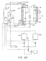
- FIGURE 2A shows a schematic diagram of a vertical basket centrifuge generally illustrating examples of the monitoring sensors, control devices and computerized control system in accordance with the present invention. A similar arrangement may be used with a horizontal basket centrifuge.
- FIGURE 2A more particularly shows centrifuge 100 having a shaft 102 for rotation, a basket 104 and screen or filter media 106 for collecting the cake 108. The cake height is shown at 110, the pool at 112, the pool height at 113, and the entry for feed and wash at 114.
- centrifuge 100 is associated with one or more sensors 120 and with one or more operational control devices 122. Both the sensors 120 and the control devices 122 communicate through a suitable communications system 124 with computer controller 126. Suitable communications systems include those known in the art, such as wiring, radio frequency methods, slip rings, and the like. Controller 126 has associated therewith a display 128 for displaying data and other parameters, and a keyboard 130 for inputting control signals, data and the like. Optionally, controller 126 has a memory or recorder 132 and a modem 134 for inputting and outputting data to the controller 126 from a remote location. One or more power sources 136 provides power to controller 126 as well as the internal and external sensors and control devices.
- the microprocessor controller 126 receives a variety of inputs which have been categorized generally in terms of (1) information stored in memory when the centrifuge is manufactured and shipped; (2) information stored in memory since the centrifuge is in operation; (3) information programmed at the site where the centrifuge is to be used; (4) operating parameters sensed by sensors 120; and (5) process parameters sensed by the sensors 120.
- Examples of information originally stored in memory include information relating to the operation and maintenance of the centrifuge and training information, all of which will be readily available to an operator on video screen 128 associated with controller 126.
- Examples of information programmed at the site where the centrifuge is to be used includes the operating parameter ranges, output parameters, desired feed properties, and other site-specific data such as ambient, temperature, relative humidity and other environmental factors.
- the outputs from the microprocessor controller may be generally categorized as (1) data stored in memory 132 associated with the controller 126, (2) operational control of the centrifuge and (3) real time information provided to the operator at the monitor 128 associated with the microprocessor 126.
- data stored in memory it will be appreciated that the computerized monitoring and control system of this invention may utilize the aforementioned sensors to monitor various parameters with respect to time and thereby provide a detailed historical record of the centrifuge operation. This record may be used by the microprocessor to model centrifuge operation, adjust models for centrifuge operation or generally learn how the centrifuge behaves in response to changes in various inputs.
- This record may also be used to provide a data log 138, provide preventative maintenance information 140, predict failure and predict machine wear 142 and filter cloth change.
- Examples of information originally stored in memory include information relating to the operation and maintenance of the centrifuge and operator training information, all of which will be readily available to an operator on display screen 128 associated with microprocessor controller 126. Operational control of the centrifuge will be described in more detail below.
- a number of sensors 120 are disclosed that sense a variety of aspects related to the centrifuge, its operations, and its input and output (filtrate and cake) streams.
- the information or parameters sensed and/or measured by these sensors include operating parameters, and input and output stream parameters.
- the operating parameters include acoustic emissions, vibration, bearing temperature, torque, amperage, rotational speed of the basket (G-level), position of internal members such as the feed inlet and the cake plow, and duration for each segment of the cycle (feeding, washing, dewatering, acceleration and deceleration).
- parameters relating to the input and output streams include the bulk density, solids concentration, and contaminant level of each of the feed, filtrate and cake (nine variables total); the mass or volumetric feed rate; temperature of feed; the solids concentration in the feed overflow; the weight of the basket content over time; the temperature of the contents within the basket; the cake height distribution circumferentially and axially with time; the cake liquid saturation; the solids volume fraction (which is the complement of cake void fraction or porosity) as a function of time; the actual internal solid/liquid separation taking place with cake formation; the height of the pool; and the hydrostatic pressure on the face of the end walls (cover lid and bottom of the basket) along the radial direction.
- the aforementioned centrifuge parameters sensed using the control system of the present invention will be more fully explained in detail hereinafter with regard to the several examples.
- the sensor or sensors comprise mass and volumetric flowmeters, density meters to measure the percent weight fraction of solids, capacitor measurement devices such as proximity gauges and conductivity probes, ultrasonic sensors and the like to measure pool level, temperature sensors, millimeter-wave length radar to monitor cake thickness submerged in the pool of liquid, in-situ infra-red beam reflectional absorbance to monitor cake moisture, and vibration sensors to measure the displacement, velocity, and acceleration of centrifuge vibration in appropriate areas.
- capacitor measurement devices such as proximity gauges and conductivity probes, ultrasonic sensors and the like to measure pool level
- temperature sensors millimeter-wave length radar to monitor cake thickness submerged in the pool of liquid
- in-situ infra-red beam reflectional absorbance to monitor cake moisture
- vibration sensors to measure the displacement, velocity, and acceleration of centrifuge vibration in appropriate areas.
- an important feature of this invention is that in response to the many parameters sensed by the sensors 120 associated with the centrifuge 100, the operation of the centrifuge and thereby its ultimate efficiency and functioning can be adjusted, changed and preferably optimized. For example, when the drop in pressure ( ⁇ p ) across the medium and cake heel becomes excessive, a thorough clean-up is required to remove the cake heel by back-blowing, using an air jet from the scraper knife or backwash. Also, if the cake heel has been removed and the resistance at the medium is still very high, blinding of the medium is indicated, and cleaning or replacing the medium is in order.
- the microprocessor may actuate a number of control devices 122 to control a number of parameters including, for example, adjustments to the speed of rotation, the flow rate and temperature of the input stream, the flow rate and temperature of the wash liquid, the pool heights, and the concentration of solids/liquids in the input stream.
- the control devices will be actuated if certain sensed parameters are outside the normal or predetermined centrifuge operating range. This operating range may be programmed into the control system either prior to or during operation.
- other outputs include the real time status of various parameters at the centrifuge.
- the operator may use the computerized control and monitoring system of the present invention to diagnose the present condition of the equipment, order spare parts including using a modem/fax 134, obtain a read-out of operating parameters, and also as part of an overall Supervisory Control and Data Acquisition (SCADA) system.
- SCADA Supervisory Control and Data Acquisition
- Suitable techniques for communicating among the sensors, microprocessor, and other components include hard-wired electrical systems, optical systems, RF systems, infra-red systems, acoustic systems, video systems, and ultrasonic systems.
- Pressure sensitive paint may also be used in conjunction with video imaging.
- the signals from a rotating unit are transmitted to the stationary laboratory reference frame through mercury slip rings.
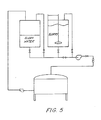
- FIGURE 2B a schematic diagram of a vertical basket centrifuge 100 is shown having basket 104, with cake 108 and pool 112. Feed from reservoir 200 and wash from reservoir 202 enter at 204.
- the feed and wash input streams into the basket are routed first through flow rate meters 206.
- Flow rate meters 206 may measure flow rate either volumetrically or by mass.
- the feed and wash input streams may also be routed through density meters 208 to measure density and solids concentration, i.e., the weight fraction of solid in the slurry.
- These analog outputs are communicated to an extraneous analog/digital converter where the signals in digital form are stored and manipulated in the CPU 126.
- Also shown in FIGURE 2B is an arrangement of pressure transducers 212 and slip rings 214 which may be used to conduct signals from the rotating basket to the stationary frame.
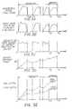
- FIGURE 2C shows measurement of the mass/volumetric rate and the percent solids or density, both of which are used in the digital processing unit to determine the cumulative solids mass input to the machine.
- Another embodiment in accordance with the present invention utilizes dilution of the feed to control the feed solids fraction as measured by density meter. This allows the maximum solids throughput without running into mechanical vibration due to mal-distribution of concentrated feed solids to the basket causing imbalance.
- FIGURE 2D shows the pressure signature of a cake submerged in the pool.
- the change in pressure between the pool and the cake ( ⁇ p ) can be directly measured.
- the liquid pressure in the basket is measured by transducers mounted at the inner surfaces of the basket end weirs along the radial direction.
- the pressure signal from the transducers mounted in the rotary basket is transmitted to cables in the stationary frame through a "slip ring" arrangement.
- the pressure profile generated by these data depicts the pool-cake interface, and further determines the pressure drop across the cake, the filter medium, and the cake heel. The latter provides an indication of blinding of medium and any significant degree of cake heel resistance. Useful diagnosis can therefore be obtained if this pressure drop becomes excessive, thereby undermining filtration, in which case cleaning or filter medium replacement is in order.
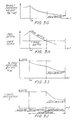
- FIGURES 3A, B, and C The expected behavior of the on-line volumetric and mass feed rate and solid concentration measurements are shown in FIGURES 3A, B, and C. Concurrently, on-line measurements of the mass of the basket contents (FIGURE 3D) and the pool-cake depths (FIGURE 3E) may be made. These measurements are also digitized and sent to the CPU.
- the slurry density is a function of time is due to the change or fluctuation of the weight concentration with time, which is itself due to fluctuation from surge tank drawdown (W(t) change with liquid level due to sedimentation in the surge tank), reactor, crystallizer or upstream separation.
- W(t) surge tank drawdown
- crystallizer or upstream separation For example, it is quite common to have a two- (or more) stage centrifugation process, each stage comprising a crystallizer, surge tank, and basket set, with one stage feeding the next stage.
- the mass of the basket contents, including both solids and liquids (M b ) is measured by the calibrated load cells 210 over a period of time.
- the measured mass of the basket contents (M b ) exhibits a behavior as illustrated in FIGURE 3G.
- Use of this measurement together with the total solids mass (M fs ), allow calculation of the cake moisture (W m ) by weight fraction averaged over the entire cake during the dewatering cycle using the following relationship: W m (t) 1 - M fs (t) M b (t)
- This relationship describes the behavior of cake moisture vs. time on-line as illustrated in FIGURE 3I.
- Both the magnitude and the rate of change of cake moisture are monitored as inputs to the controller. If the cake moisture is set at a given level, i.e, by being programmed into the controller, the deduced cake moisture can be compared with the setting. Thus, the dewatering time can be extended if the deduced cake moisture is higher, or the dewatering cycle can be terminated in the event that the deduced moisture is lower compared to the set point.
- Such control may be exercised automatically, under direction from the controller on a control device, or by an operator. Alternatively, the operator can terminate the dewatering when the rate of change of the cake moisture is less that 0.1% in a given time period.
- data obtained by sensing the liquid pool depth at a given time, together with the cake height measurement can yield information on the total filtration resistance of the cake (inversely, cake permeability), cake heel resistance, liquid saturation in the cake, and solids volume fraction of the cake (inversely, cake porosity).
- Sensing the liquid pool depth at a given time during the feed or wash cycle can be accomplished by means known in the art, for example, radio frequency sensors, i.e., radio frequency reflectance sensors, contact sensors, or conductivity sensors. These data may be used to determine the change in liquid level above the sediment cake having thickness h.
- the solids volume fraction ( ⁇ s ) and the liquid saturation (S) can be determined by first deducing the cake volume from the following relationship where:
- a plot of ⁇ vs. log 10 yields a straight line trend through the test data.
- the cake resistance (inverse of he cake permeability) may be deduced from the slope of the linear trend, and the intercept provides information on the cake heel/filter medium resistance.
- Measurements of the radii may be made by contact or non-contact methods known in the art, for example sonar or ultrasound imaging, infra-red and ultrasonic reflection, and the like.
- the controller can use a control device in the next cycle to increase the feed rate, to lower the solids content of the feed by using a shorter feed time, or add body, filter aid, into the feed, for example.
- Lowering the solids content results in a smaller cake height and less dewatering time to reach the specified cake moisture.
- the shorter cycle time at smaller cake depth might be more than offset by having more cycles within the same time frame, thereby resulting in an actual increase in throughput capacity at the same discharged cake moisture.
- Adding body, also known as filter aid introduces particles, such as diatomaceous earth which is compatible with the solids, to the feed to provide a more permeable cake structure for filtration. This optimization process is best achieved by a computerized controller as discussed herein.
- cake heel resistance as determined from the resistance-cake radii plot, becomes too high a cake heel purge and/or filter medium change should be scheduled in the next cycle to restore filtration rate, before the filtration rate drops off dramatically due to high cake heel/medium resistance.
- Preferably more than two different cake heights will be tested, yielding a series of data with a linear trend, allowing prediction as to when the purge is needed.
- the levels of cake contaminants are measured, for example by measuring the contaminant exiting with the filtrate. Methods known in the art may be used, for example, using probes sensitive to contaminant level by measuring conductivity or ion content in solution. On-line sampling followed, for example, by gas chromatography-mass spectroscopy (GC-MS) or other analytical analysis may also be used. Given that the filtrate and cake contaminant levels are closely related as shown in FIGURE 3F, these measurements can be used to tailor or optimize the amount of wash liquid used to wash the cake (the wash ratio) and/or tailor or to optimize the G-force required during the wash cycle.
- GC-MS gas chromatography-mass spectroscopy
- Another preferred embodiment for controlling the contaminant is to control the wash liquid (rate and sequence), and/or the G-force applied during cake washing, based on the magnitude and rate of change of contaminant in the filtrate.
- the wash liquid should be applied before the pool subsides below the cake surface to avoid cake cracking.
- data obtained by sensing torque and amperage can be correlated with the overall basket mass (more properly the moment of inertia which affects the acceleration and deceleration time).
- Another embodiment in accordance with the present invention is to control the separation process by passing the feed to a heat exchanger prior to feeding the basket.
- the reduction in viscosity via temperature adjustments enhances filtration.
- Hot wash liquid would further provide effective wash as well as facilitating improved dewatering due to viscosity reduction, as a wash liquid at elevated temperature is often used to effectively displace contaminants within the mother liquor.
- Viscosity may be reduced to one-half and one-third of the value at room temperature at, respectively, 55°C and 75°C.
- a parameter is controlled to optimize the feeding cycle is to feed the machine until the slurry pool reaches a prescribed height, for example about 80-90% of the weir height (as measured by conductivity probe, capacitance probe, ultrasonic, radio frequency, or mechanical arm or the like) and then to "catch up" until the slurry pool drops back to a second prescribed weir height, for example, about 60-75%, after which the sequence repeats itself.
- a prescribed height for example about 80-90% of the weir height (as measured by conductivity probe, capacitance probe, ultrasonic, radio frequency, or mechanical arm or the like) and then to "catch up" until the slurry pool drops back to a second prescribed weir height, for example, about 60-75%, after which the sequence repeats itself.
- the weight of the basket contents is monitored in real time and control of feeding is based on prior experience in loading the basket for a given slurry, for example, where feeding of the basket is stopped when the weight of the container exceed a given mass
- the feed rate can be trimmed off after the initial period when the slurry pool reaches the predetermined maximum pool of 80-95% of the weir height.
- the feed rate can be adjusted to the filtration rate so that the driving liquid head and thus the filtration rate stay constantly at maximum. This requires the pool level to remain at the maximum level.
- the feeding cycle time can thereby be substantially reduced.
- the cake height is monitored during feeding, for example by the millimeter wave radar, until it reaches the desired thickness.
- a preferred method of controlling the cake moisture is to adjust basket speed, thus the G-force, cake depth, and dewatering time. These adjustments may be based on the deduced average cake moisture/dryness at any time using the measured mass balance.
- the mass balance may be determined from measurements made by strain gauges embedded in the hoops of the basket, which measure the hoop stresses on the basket.
- the cake moisture can be measured in situ by directing an infrared beam onto the surface of the cake inside the basket, or onto the cake as the cake is discharged from the basket.
- the infra-red source and pick-up may be fixed at a given axial location, and the moisture measurements made on the rotating cake on the basket represents an average cake moisture around the circumference.
- the infrared source and pick-up can be mounted on a traveller mechanism which traverses along the axis of the basket, thus allowing the cake moisture distribution to be determined in the entire basket. Diagnosis of potential problems as well as optimization can therefore be made on a finer scale.
- an infrared beam or conductivity probe can be respectively directed at or mounted in the discharged cake.
- the moisture level of the cake may be deduced from this data. In both cases, this data is fed back to the controller to adjust the dewatering time for the subsequent batches.
- intrusive sensors such as electrical conductivity probes can also be adopted as appropriate.
- Another particularly preferred embodiment is where the basket is "overfed", causing the supernatant of the rapidly settled slurry to overflow the weir which contains the annular pool. This supernatant overflow is then returned to the feed tank upstream.
- the suspended solids concentration in the supernatant overflow is monitored, for example by a density meter, to ensure that the solids concentration is significantly below that of the feed. Where the suspended solids concentration in the overflow is too high, the rate of the feed must be reduced, or the feed must be diluted.
- the actual internal separation taking place with cake formation can be shown by an imaging sensor, e.g., shown visually by a camera, millimeter wave radar imaging, or the equivalent.
- the vibration of the basket is monitored, especially during feeding, where machine imbalance might result from uneven distribution of the feed in the basket both circumferentially and longitudinally.
- the feed slurry may be adjusted, typically by dilution, to reduce hindered settling which results in slow cake formation. Therefore, hindered settling may be detected by monitoring the cake height over time.
- a further embodiment in accordance with the present invention, controls the nominal solids throughput rate by optimizing the batch cycle time and the solids mass per batch. For example, it may be possible to filter a given mass for a given period, for example five pounds in ten minutes. Through trials, it may also be possible to filter a lesser amount of the same feed input, for example two and a half pounds in a lesser amount of time, for example three minutes. Running three cycles under these latter conditions would result in the filtration of seven and one-half pounds in nine minutes, a higher rate than five pounds in ten minutes. The highest throughput rate is therefore obtained by filtering smaller batches for shorter cycle time. The highest throughput rate depends on the filtration, washing, and dewatering characteristics of the input feed. Trial and analysis of these variables is best adapted using computerized intelligence for determining the optimal operating condition according to the feed condition and set goal for separation, both of which may change with time. The same approach may be used to attain optimal cake moisture and optimal cake purity.
- the intelligent vertical centrifuge in accordance with the present invention is equipped with load cells from which the mass of the basket contents can be determined in real time. This data is provided to a computer and with the methodology discussed, it is translated to cake moisture; information which is available on-line.
- the basket operation is controlled through manipulation of the various segments of acceleration, feeding, washing, dewatering, and unloading, all of which are programmed on an interactive basis.
- the basket is further equipped with air blow-back from the basket outer radius to discharge the cake heel. A set of air jets at the two corners of the blade edge (in contact with the cake) of the unloader knife further facilitates the removal of cake heel.
- the basket is also equipped with ample wash nozzles to provide "clean-in-place” and "sanitary-in-place” capabilities with minimal-to-no solids trapped within the basket. This is an important requirement for pharmaceutical and specialty chemicals processing, where the value of solid is high and loss of solid or contamination from the previous batch of different products cannot be tolerated.
- the basket is also equipped with higher G-force for machines with comparable size. For a 60" diameter basket, the maximum G is 1000 g and for a smaller 38" basket, the G-force reaches 1500 g.
- the number of bags of slurry and quantity of water added to form the slurry are carefully recorded.
- the centrifuge is accelerated to the desired G-level of cake formation.
- a fixed amount of well-mixed slurry is then metered into the centrifuge, as measured by the flowmeter, to yield the desired cake height.
- the feed time is monitored using a stop-watch. Once the designated amount of slurry has been added, the feed valve is shut, the pump is turned off, and the slurry tank valve is closed. The feed time and the total mass of the basket contents are recorded.
- the total mass of the basket contents are recorded.
- the centrifuge is stopped, and the mass of the final basket contents after deceleration, along with the deceleration time are recorded.
- the axial cake height is measured and recorded axially at the top, middle and bottom of the basket.
- samples are taken using containers from each of these locations. The samples and containers are subsequently weighed and dried in an oven overnight. The dry sample weights are determined, and the moisture of the cake calculated.
- the centrifuge After measuring the cake heights and taking the samples, the centrifuge is spun up to high speed (1080 rpm) to fully dewater the cake. The dry cake is finally discharged using the computer-driven control features of the centrifuge, including the plow to remove the bulk of the cake, and the back-blow and air knife to remove the cake heel. After the discharge cycle, the cloth is inspected for any tears and residual cake heel.
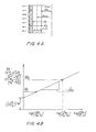
- FIGURES 6, 7, and 8 show plots of the cake moisture and cake height as a function of axial position at representative G-levels, and the dewatering times for each of three DE (diatomaceous earth) cake materials.
- DE which is derived from seaweed, is commonly used to enhance cake filtration.
- These plots indicate the axial moisture distribution and the axial cake geometry.
- the cake moisture increases while the cake height decreases towards the top, as shown in FIGURES 6 and 7.
- FIGURE 8 also shows similar trends. However, the minimum moisture is observed in the middle, whereas for the smaller median particle size DE materials, the minimum moisture is observed at the bottom.
- the measured moisture at the middle of each cake is selected as representative of the cake, and plotted against the dimensionless dewatering parameter Td for two test materials in FIGURES 9 and 10.
- Td is proportional to the variables regrouped in the form of G-seconds/cake height.
- the predicted cake moisture, using a macroscopic mass balance as discussed in the theory section, is also plotted alongside the measured moisture. The agreement between the measured values and predicted values is quite good for 16.4- ⁇ m median particle size DE, and excellent for 28.6- ⁇ m median particle size DE, as shown in FIGURES 9 and 10.
Applications Claiming Priority (3)
| Application Number | Priority Date | Filing Date | Title |
|---|---|---|---|
| US5311797P | 1997-07-18 | 1997-07-18 | |
| US53117P | 1997-07-18 | ||
| EP98112289A EP0891814B1 (fr) | 1997-07-18 | 1998-07-02 | Procédé et appareil pour réglage de centrifugeuses à paniers verticaux et horizontaux |
Related Parent Applications (1)
| Application Number | Title | Priority Date | Filing Date |
|---|---|---|---|
| EP98112289A Division EP0891814B1 (fr) | 1997-07-18 | 1998-07-02 | Procédé et appareil pour réglage de centrifugeuses à paniers verticaux et horizontaux |
Publications (1)
| Publication Number | Publication Date |
|---|---|
| EP1256384A2 true EP1256384A2 (fr) | 2002-11-13 |
Family
ID=26149393
Family Applications (1)
| Application Number | Title | Priority Date | Filing Date |
|---|---|---|---|
| EP02015353A Withdrawn EP1256384A2 (fr) | 1997-07-18 | 1998-07-02 | Procédé et appareil pour réglage de centrifugeuses à paniers verticaux et horizontaux |
Country Status (1)
| Country | Link |
|---|---|
| EP (1) | EP1256384A2 (fr) |
Cited By (4)
| Publication number | Priority date | Publication date | Assignee | Title |
|---|---|---|---|---|
| CN108871429A (zh) * | 2018-05-09 | 2018-11-23 | 宜兴市华鼎机械有限公司 | 一种两相、三相离心机全息监测方法及系统 |
| CN112742610A (zh) * | 2020-12-29 | 2021-05-04 | 江苏华铖宝亿机械有限公司 | 一种高性能便于使用的碟式分离机及使用方法 |
| WO2022090632A1 (fr) * | 2020-10-30 | 2022-05-05 | Metso Outotec Finland Oy | Dispositif et procédé de commande d'un filtre sous pression |
| CN115487579A (zh) * | 2022-09-26 | 2022-12-20 | 重庆江北机械有限责任公司 | 一种活塞推料离心机自适应适时控制方法及装置 |
Citations (2)
| Publication number | Priority date | Publication date | Assignee | Title |
|---|---|---|---|---|
| US5004540A (en) | 1989-12-01 | 1991-04-02 | Ketema Process Equipment Division | Invertible filter-type centrifuge with improved bearing and seal assembly |
| US5582742A (en) | 1995-09-05 | 1996-12-10 | Ketema, Inc. | Rotary distribution pipe assembly |
-
1998
- 1998-07-02 EP EP02015353A patent/EP1256384A2/fr not_active Withdrawn
Patent Citations (2)
| Publication number | Priority date | Publication date | Assignee | Title |
|---|---|---|---|---|
| US5004540A (en) | 1989-12-01 | 1991-04-02 | Ketema Process Equipment Division | Invertible filter-type centrifuge with improved bearing and seal assembly |
| US5582742A (en) | 1995-09-05 | 1996-12-10 | Ketema, Inc. | Rotary distribution pipe assembly |
Cited By (5)
| Publication number | Priority date | Publication date | Assignee | Title |
|---|---|---|---|---|
| CN108871429A (zh) * | 2018-05-09 | 2018-11-23 | 宜兴市华鼎机械有限公司 | 一种两相、三相离心机全息监测方法及系统 |
| WO2022090632A1 (fr) * | 2020-10-30 | 2022-05-05 | Metso Outotec Finland Oy | Dispositif et procédé de commande d'un filtre sous pression |
| CN114432754A (zh) * | 2020-10-30 | 2022-05-06 | 美卓奥图泰芬兰有限公司 | 控制压力过滤器的设备和方法 |
| CN112742610A (zh) * | 2020-12-29 | 2021-05-04 | 江苏华铖宝亿机械有限公司 | 一种高性能便于使用的碟式分离机及使用方法 |
| CN115487579A (zh) * | 2022-09-26 | 2022-12-20 | 重庆江北机械有限责任公司 | 一种活塞推料离心机自适应适时控制方法及装置 |
Similar Documents
| Publication | Publication Date | Title |
|---|---|---|
| US6063292A (en) | Method and apparatus for controlling vertical and horizontal basket centrifuges | |
| US6143183A (en) | Method and apparatus for controlling and monitoring continuous feed centrifuge | |
| JP6698254B2 (ja) | 遠心分離機の動作を監視及び/又は調整するための方法 | |
| WO1999015255A1 (fr) | Procede et dispositif servant a effectuer le controle, la commande et la mise en service de filtres rotatifs a tambour | |
| KR101925321B1 (ko) | 고액 분리장치 | |
| US20160251605A1 (en) | Method for clarifying a flowable product by way of a centrifuge | |
| EP1256384A2 (fr) | Procédé et appareil pour réglage de centrifugeuses à paniers verticaux et horizontaux | |
| DE102008062055B4 (de) | Verfahren zur Überwachung der automatisierten Entleerung einer Zentrifuge | |
| US10745310B2 (en) | Dewatering systems and methods | |
| WO2014174258A1 (fr) | Centrifugeuse et son système de commande | |
| EP1475156B1 (fr) | Commande de charge pour centrifuges | |
| US20050000869A1 (en) | Device for determining the residual liquid content of solids cakes in centrifuges | |
| CN214373757U (zh) | 一种土壤检测用土壤筛分装置 | |
| Luckiram | Centrifugation | |
| US6296774B1 (en) | Centrifuge load control for automatic infeed gate adjustment | |
| Todaro | Centrifugation | |
| CA3222056A1 (fr) | Appareil et processus de traitement complet de suspension et de poudre | |
| DE10323516B3 (de) | Vorrichtung zur Entfeuchtungsmessung zur Steuerung einer Filterzentrifuge | |
| KR102221961B1 (ko) | 원심분리 여과기의 중심축과 슬러리액벽까지 거리를 비접촉식으로 측정한 데이터를 활용한 슬러리 고액분리 처리장치 및 그 스마트 운전방법 | |
| JP2002139595A (ja) | 放射性廃液処理システム | |
| WO2022268516A1 (fr) | Procédé de fonctionnement d'un séparateur centrifuge | |
| SANTHANAM et al. | 8.7 Centrifuge Controls | |
| CN116457104A (zh) | 用于确定在分离机的转筒内的污染物的范围的方法以及分离机 | |
| JPH09164309A (ja) | 濾過乾燥機のケーキ検知装置 |
Legal Events
| Date | Code | Title | Description |
|---|---|---|---|
| PUAI | Public reference made under article 153(3) epc to a published international application that has entered the european phase |
Free format text: ORIGINAL CODE: 0009012 |
|
| 17P | Request for examination filed |
Effective date: 20020710 |
|
| AC | Divisional application: reference to earlier application |
Ref document number: 891814 Country of ref document: EP |
|
| AK | Designated contracting states |
Kind code of ref document: A2 Designated state(s): CH DE GB IT LI |
|
| STAA | Information on the status of an ep patent application or granted ep patent |
Free format text: STATUS: THE APPLICATION HAS BEEN WITHDRAWN |
|
| 18W | Application withdrawn |
Effective date: 20040510 |