EP1256379B1 - Geordnete stoffaustauschpackung mit randabweisern - Google Patents
Geordnete stoffaustauschpackung mit randabweisern Download PDFInfo
- Publication number
- EP1256379B1 EP1256379B1 EP02009784.6A EP02009784A EP1256379B1 EP 1256379 B1 EP1256379 B1 EP 1256379B1 EP 02009784 A EP02009784 A EP 02009784A EP 1256379 B1 EP1256379 B1 EP 1256379B1
- Authority
- EP
- European Patent Office
- Prior art keywords
- packing
- film
- mass transfer
- packing element
- upper rim
- Prior art date
- Legal status (The legal status is an assumption and is not a legal conclusion. Google has not performed a legal analysis and makes no representation as to the accuracy of the status listed.)
- Expired - Lifetime
Links
- 238000012856 packing Methods 0.000 title claims description 61
- 229920006300 shrink film Polymers 0.000 claims description 10
- 239000004810 polytetrafluoroethylene Substances 0.000 claims description 7
- 229920001343 polytetrafluoroethylene Polymers 0.000 claims description 7
- 229920001577 copolymer Polymers 0.000 claims description 5
- 238000010521 absorption reaction Methods 0.000 claims description 3
- 238000003795 desorption Methods 0.000 claims description 3
- 238000000605 extraction Methods 0.000 claims description 3
- -1 polytetrafluoroethylene Polymers 0.000 claims description 3
- 239000002985 plastic film Substances 0.000 claims description 2
- 229920006255 plastic film Polymers 0.000 claims description 2
- 239000012530 fluid Substances 0.000 claims 1
- 230000002093 peripheral effect Effects 0.000 claims 1
- 239000004033 plastic Substances 0.000 description 9
- 229920003023 plastic Polymers 0.000 description 9
- 239000000463 material Substances 0.000 description 7
- 238000000034 method Methods 0.000 description 7
- 239000011521 glass Substances 0.000 description 3
- 238000005520 cutting process Methods 0.000 description 2
- 230000000694 effects Effects 0.000 description 2
- 239000011888 foil Substances 0.000 description 2
- 239000007788 liquid Substances 0.000 description 2
- 238000004519 manufacturing process Methods 0.000 description 2
- 230000006978 adaptation Effects 0.000 description 1
- 238000005452 bending Methods 0.000 description 1
- 239000002131 composite material Substances 0.000 description 1
- 230000002950 deficient Effects 0.000 description 1
- 238000001125 extrusion Methods 0.000 description 1
- 238000010438 heat treatment Methods 0.000 description 1
- 239000007791 liquid phase Substances 0.000 description 1
- 238000003466 welding Methods 0.000 description 1
Images

Classifications
-
- B—PERFORMING OPERATIONS; TRANSPORTING
- B01—PHYSICAL OR CHEMICAL PROCESSES OR APPARATUS IN GENERAL
- B01J—CHEMICAL OR PHYSICAL PROCESSES, e.g. CATALYSIS OR COLLOID CHEMISTRY; THEIR RELEVANT APPARATUS
- B01J19/00—Chemical, physical or physico-chemical processes in general; Their relevant apparatus
- B01J19/32—Packing elements in the form of grids or built-up elements for forming a unit or module inside the apparatus for mass or heat transfer
- B01J19/325—Attachment devices therefor, e.g. hooks, consoles, brackets
-
- B—PERFORMING OPERATIONS; TRANSPORTING
- B01—PHYSICAL OR CHEMICAL PROCESSES OR APPARATUS IN GENERAL
- B01J—CHEMICAL OR PHYSICAL PROCESSES, e.g. CATALYSIS OR COLLOID CHEMISTRY; THEIR RELEVANT APPARATUS
- B01J2219/00—Chemical, physical or physico-chemical processes in general; Their relevant apparatus
- B01J2219/32—Details relating to packing elements in the form of grids or built-up elements for forming a unit of module inside the apparatus for mass or heat transfer
- B01J2219/322—Basic shape of the elements
- B01J2219/32203—Sheets
- B01J2219/32275—Mounting or joining of the blocks or sheets within the column or vessel
Definitions
- the invention relates to an ordered mass transfer packing with novel edge deflectors.
- Ordered packs consisting of sections superimposed in the column packing elements which either fill the column cross-section as a single column adapted to the cross section of the column or substantially, especially at larger clearances Widths of the columns, in turn, are constructed of individual segments, which are for example cake-pieced combined to form a composite packing element.
- Ordered mass transfer packages exist in various configurations and may consist of different materials.
- a preferred type of ordered mass transfer packs are those made of glass, for example those made by bonding glass corrugated sheets, as in US Pat DE 39 09 995 C1 and the DE 41 28 675 C2 is described.
- Such ordered mass transfer packs are sold under the brand DURAPACK ® and described in terms of their structure and their use in the brochures for such DURAPACK ® packings closer.
- the present invention is not limited to use with such glass mass transfer packs. but may also be used in conjunction with other ordered mass transfer packs of other materials, such as those described in the preamble of the patent DE 41 28 675 C2 be mentioned.
- the packing elements of such ordered mass transfer packings are arranged one above the other in sections in the column cross-section, wherein to avoid a too high resulting total own weight ring supports or supporting grids can be used. It is desirable that the packing elements fill the column cross-section as completely as possible. However, it is inevitable that between the circumference of the packing elements and the column wall more or less pronounced edge columns are formed, which means that in the mass transfer processes in the column downwardly moving liquid phase runs partially on the column inner wall down and thereby the intensive Mass transfer within the packing elements is withdrawn. This process is referred to as "Randitkeit" and reduces the desired mass transfer performance of the column.
- the marginal gaps can have very different widths of fractions of millimeters up to several millimeters.
- edge deflectors In order to suppress this marginality as possible, it is known to provide the mass transfer packs with so-called edge deflectors. These can be referred to essentially as upwardly flared conical or funnel-shaped rings which extend directly to the column inner wall and at the column inner wall downwardly flowing liquid portions ein réelle inside the packing elements.
- edge deflector are from the documents JP 11099329 A and US-A-5,224,351 known.
- Randabweiser In order to attach such Randabweiser to mass transfer packs, it is currently primarily so that you insert preformed annular Randabweiser of PTFE or other suitable plastics between the packing elements.
- an ordered mass transfer packing for absorption, desorption, rectification or extraction columns which is composed of individual packing elements or packing elements, which are composed of segments, and provided with Randabweisern to avoid Randzankeit the column characterized in that the edge deflector (2) is formed as a conical edge of a plastic film which is formed by a on the periphery of the packing element (1) or the segment of a packing element foil strip (3) made of a polytetrafluoroethylene film whose upper edge region at least partially bent outwards from the circumference of the packing element (1) and that of a shrink film ring (4) shrunk onto the circumference of the packing element (1) and made of a tetrafluoroethylene copolymer on the surface of the packing element (1) or segment Packing element is held.
- edge deflectors are given in claims 2 to 5.
- the edge deflector is formed by a film strip or film strip applied to the circumference of the packing element or the segment of a packing element, the upper edge region of which is angled outwards and, after being placed on the circumference of the packing element, by a shrunk-on shrink film section on the surface the packing element or segment of the packing element is held.
- FIGS. 1 and 2 The invention is characterized by the FIGS. 1 and 2 explained in more detail. It shows FIG. 1 a packing element 1 with a Randabweiser 2, which is composed of a wrapped around the packing element 1 around film strip 3 and a shrunk shrink film 4 ring.
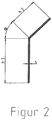
- FIG. 2 shows a cross section of a film strip or -bandes 3, as it is in FIG. 1 can be used.
- the edge portion of the edge deflector forming the conical edge may be slotted, i. have approximately in the radial direction extending cuts or notches.
- the plastic materials used for the production of the Randabweiser must be those which are chemically inert and sufficiently dimensionally stable under the conditions that prevail in the mass transfer processes within the respective column.
- the films have to be made from sufficiently heat-resistant plastics and are formed from polytetrafluoroethylene (PTFE).
- edge deflectors When making the edge deflectors from strip materials, it is preferred to make film strips or film tapes with a longitudinal kink or possibly also a longitudinal fold facilitating bending of the top edge of the film strip, with respect to the annular arrangement of the strip for producing the edge deflectors in the angled range cuts or notches may be provided. Such film strips or film strips can be produced, for example, advantageously by extrusion through a suitable nozzle profile.
- the film strip is divided longitudinally so as to form an angled top edge which is from about 20 to about 40% of the total width of the film strip and is angled such that the included angle of the bend is between 110 and 160 °, preferably about 135 °.
- This angle corresponds to an angle ⁇ of the bend of the funnel-like edge to the outside of 20 to 70 °, preferably about 45 °.
- the "funnel angle" ⁇ occurs identically also in the FIG. 1 shown Set up. It is within the scope of the present invention to provide that the angled edge is shortened prior to assembly of the film strip by cutting in the longitudinal direction, in order to achieve a better adaptation to narrower or more marginal gaps.
- the edge deflectors are fastened by shrinking a tubular or annular shrink film on the package or the packing elements.
- plastic materials must also be used for the shrink film that are sufficiently inert under the conditions prevailing in the column and do not lose their internal strength and dimensional stability. Suitable materials are tetrafluoroethylene copolymers, a particularly suitable material being a tetrafluoroethylene-hexafluoropropylene copolymer (FEP).
- FEP tetrafluoroethylene-hexafluoropropylene copolymer
- plastic hoses of a suitable width are available, sections of such plastic hoses can be loosely pushed onto the packing elements and then shrunk. Besides these plastic hoses clamping the edge deflectors, they also hold together the packing elements or segments of packing elements and thereby stabilize the packages.
- the shrink film is shrunk annularly onto the individual packing element, wherein two edge deflectors are preferably provided per packing element in order to better compensate for changing tolerances of the column or the packing element.
- the packing elements are made up of individual segments, this is the case possible to shrink the shrink film around the individual segments around and to provide only those sections that form the inside of the column facing the handling of the finished package, with Randabweisern by arranging only in this area angled foil strips only in this area.
- the tube ring may also be formed of an endless shrink-wrap band, of which a section is made into a ring of the required diameter and its ends joined, for example by a suitable welding technique.
- the band or strip Randabweiser can be inexpensively manufactured as an endless belt and adapted by simply cutting to a variety of column diameters.
- edge deflectors In the production of the edge deflectors, one can use a method that can be described as applying a tape from an angled film strip on the circumference of a packing element and pushing a hose section on the packing element and the adjacent substantially cylindrical ring edge of the film strip and subsequent heating of the loose Bonding under shrinking the section of the film tube.
Landscapes
- Chemical & Material Sciences (AREA)
- Physics & Mathematics (AREA)
- Thermal Sciences (AREA)
- Organic Chemistry (AREA)
- Chemical Kinetics & Catalysis (AREA)
- Packages (AREA)
- Gasket Seals (AREA)
Description
- Die Erfindung betrifft eine geordnete Stoffaustauschpackung mit neuartigen Randabweisern.
- Es ist bekannt, in Kolonnen, in denen Stoffaustauschvorgänge ablaufen, d.h. insbesondere in Absorptions-, Desorptions-, Rektifikations- oder Extraktionskolonnen, sog. geordnete Packungen einzusetzen, die aus abschnittsweise übereinander in der Kolonne angeordneten Packungselementen bestehen, die entweder als einzelne dem Kolonnenquerschnitt angepaßte Packungselemente den Kolonnenquerschnitt im wesentlichen füllen oder die, insbesondere bei größeren lichten Weiten der Kolonnen, ihrerseits aus einzelnen Segmenten aufgebaut sind, die beispielsweise tortenstückartig zu einem zusammengesetzten Packungselement kombiniert sind.
- Geordnete Stoffaustauschpackungen existieren in verschiedenen Ausgestaltungen und können aus verschiedenen Materialien bestehen. Eine bevorzugte Art von geordneten Stoffaustauschpackungen sind solche aus Glas, beispielsweise solche, die durch Verbinden von Glaswellplatten hergestellt werden, wie in der
DE 39 09 995 C1 und derDE 41 28 675 C2 beschrieben ist. Derartig geordnete Stoffaustauschpackungen werden unter der Marke DURAPACK® vertrieben und im Hinblick auf ihren Aufbau und ihre Verwendung in den Prospekten für derartige DURAPACK®-Packungen noch näher erläutert. - Die vorliegende Erfindung ist jedoch nicht auf eine Verwendung mit derartigen Glas-Stoffaustauschpackungen beschränkt, sondern kann auch in Verbindung mit anderen geordneten Stoffaustauschpackungen aus anderen Materialien verwendet werden, beispielsweise solchen, wie sie in der Einleitung des Patents
DE 41 28 675 C2 erwähnt werden. - Die Packungselemente derartiger geordneter Stoffaustauschpackungen werden abschnittsweise übereinander im Kolonnenquerschnitt angeordnet, wobei zur Vermeidung eines zu hohen resultierenden Gesamt-Eigengewichts Ringauflagen oder Tragroste zur Anwendung kommen können. Es wird dabei angestrebt, dass die Packungselemente den Kolonnenquerschnitt möglichst vollständig ausfüllen. Es ist jedoch unvermeidlich, dass zwischen dem Umfang der Packungselemente und der Kolonnenwand mehr oder weniger ausgeprägte Randspalten gebildet werden, was dazu führt, dass die sich bei Stoffaustauschprozessen in der Kolonne nach unten bewegende flüssige Phase teilweise an der Kolonneninnenwand nach unten abläuft und dadurch dem intensiven Stoffaustausch innerhalb der Packungselemente entzogen wird. Dieser Vorgang wird als "Randgängigkeit" bezeichnet und vermindert die gewünschte Stoffaustauschleistung der Kolonne. Die Randspalten können dabei sehr unterschiedliche Breiten von Bruchteilen von Millimetern bis hin zu mehreren Millimetern aufweisen.
- Um diese Randgängigkeit möglichst zurückzudrängen, ist es bekannt, die Stoffaustauschpackungen mit sogenannten Randabweisern zu versehen. Diese können im Wesentlichen als sich nach oben erweiternde konische oder trichterförmige Ringe bezeichnet werden, die direkt bis an die Kolonneninnenwand reichen und an der Kolonneninnenwand nach unten strömende Flüssigkeitsanteile ins Innere der Packungselemente zurückleiten.Derartige Randabweiser sind aus den Schriften
JP 11099329 A US-A-5,224,351 bekannt. Um derartige Randabweiser an Stoffaustauschpackungen anzubringen, geht man derzeit in erster Linie so vor, dass man vorgeformte ringförmige Randabweiser aus PTFE oder anderen geeigneten Kunststoffen zwischen die Packungselemente einlegt. Das hat einerseits den Nachteil, dass die zwischen den einzelnen Packungselementen angeordneten Ringe an der entsprechenden Stelle den Strömungsquerschnitt zwischen den Packungselementen verringern, und dass außerdem bei der Montage der Packungselemente in der Regel Spannungen auftreten, die dazu führen, dass der bekannte ringförmige Randabweiser und damit auch dessen abgeschrägter Rand verzogen wird und nicht gleichmäßig an der Innenwand der Kolonne anliegt, sondern wellenförmig verzogen ist, wodurch die Randabdichtung mangelhaft wird und sich in den gebildeten Tälern Flüssigkeit ansammeln kann. - Es ist ferner bekannt, Randabweiser so an geordneten Packungen anzubringen, dass man eine abgeschrägte Folie aus PTFE oder einem anderen Kunststoff dadurch am Rand der Packung befestigt, dass man den senkrechten Teil der Folie mit einem um die Packung gelegten zweiten PTFE- oder Kunststoffring vernäht. Dieses Verfahren ist arbeitsaufwändig.
- Es ist Aufgabe der vorliegenden Erfindung, unter Beibehaltung bzw. Verbesserung der gewünschten Stoffaustauschwirkung der Packungselemente die Anbringung von Randabweisern zu vereinfachen und deren Wirkung zu optimieren.
- Diese Aufgabe wird gemäß Anspruch 1 bei einer geordneten Stoffaustauschpackung für Absorptions-, Desorptions-, Rektifikations- oder Extraktionskolonnen, die aus einzelnen Packungselementen oder aus Packungselementen, die aus Segmenten zusammengesetzt sind, aufgebaut ist und mit Randabweisern zur Vermeidung einer Randgängigkeit der Kolonne versehen ist, dadurch gelöst, dass der Randabweiser (2) als konischer Rand aus einer Kunststofffolie ausgebildet ist, der von einem auf den Umfang des Packungselements (1) oder des Segments eines Packungselements aufgelegten Folienstreifen (3) aus einer Polytetrafluorethylen-Folie gebildet wird, dessen oberer Randbereich wenigstens teilweise vom Umfang des Packungselements (1) nach außen abgebogen ist und der von einem auf den Umfang des Packungselements (1) aufgeschrumpften Schrumpffolienring (4) aus einem Tetrafluorethylen-Copolymer auf der Oberfläche des Packungselements (1) oder Segments des Packungselements gehalten wird.
- Merkmale vorteilhafter Ausgestaltungen erfindungsgemäßer Randabweiser sind den Ansprüchen 2 bis 5 wiedergegeben.
- Nachfolgend wird die Erfindung noch in näheren Einzelheiten erläutert, wobei zur Veranschaulichung auf zwei Figuren Bezug genommen wird.
- Darin zeigen:
- Figur 1
- ein Packungselements (1) mit einem Randabweiser (2), der von einem auf das Packungselement (1) aufgelegten abgewinkelten Folienstreifen (3) und einem diesen haltenden Schrumpffolienring (4) gebildet wird; und
- Figur 2
- eine bevorzugte Ausführungsform eines Folienstreifens zu Verwendung in einem Randabweiser gemäß
Figur 1 . - Im Rahmen der vorliegenden Erfindung wird der Randabweiser von einem auf den Umfang des Packungselements oder des Segments eines Packungselements aufgelegten Folienstreifen oder Folienband gebildet, dessen oberer Randbereich nach außen abgewinkelt ist und der nach seinem Auflegen auf den Umfang des Packungselements von einem aufgeschrumpften Schrumpffolienabschnitt auf der Oberfläche des Packungselements oder Segments des Packungselements gehalten wird.
- Die Erfindung wird durch die
Figuren 1 und2 näher erläutert. Dabei zeigtFigur 1 ein Packungselement 1 mit einem Randabweiser 2, der sich aus einem um das Packungselement 1 herum gelegten Folienstreifen 3 und einem aufgeschrumpften Schrumpffolienring 4 zusammensetzt. -
Figur 2 zeigt einen Querschnitt eines Folienstreifens oder -bandes 3, wie es inFigur 1 zur Anwendung kommen kann. - Zur Vermeidung von Spannungen im Umfangsbereich und von durch Verziehen entstehenden Unregelmäßigkeiten sowie zur leichteren Anpassung an unterschiedliche Kolonnendurchmesser kann der den konischen Rand bildende Randbereich des Randabweisers geschlitzt sein, d.h. in etwa in radialer Richtung verlaufende Schnitte oder Kerben aufweisen.
- Es versteht sich, dass die zur Herstellung der Randabweiser verwendeten Kunststoffmaterialien solche sein müssen, die unter den Bedingungen, die bei den Stoffaustauschvorgängen innerhalb der jeweiligen Kolonne herrschen, chemisch inert und ausreichend formstabil sind. Die Folien müssen mit anderen Worten aus ausreichend wärmebeständigen Kunststoffen hergestellt werden und sind aus Polytetrafluorethylen (PTFE) gebildet .
- Wenn man die Randabweiser aus streifenförmigen Materialien herstellt, ist es bevorzugt, Folienstreifen oder Folienbänder mit einem in Längsrichtung verlaufenden Knick herzustellen oder ggf. auch mit einem in Längsrichtung verlaufenden Falz, der ein Abbiegen der Oberkante des Folienstreifens erleichtert, wobei im Hinblick auf die ringförmige Anordnung des Streifens zur Herstellung der Randabweiser im abzuwinkelnden Bereich Schnitte oder Kerben vorgesehen sein können. Derartige Folienstreifen oder Folienbänder lassen sich beispielsweise vorteilhaft durch Extrusion durch ein geeignetes Düsenprofil herstellen. Bei einer bevorzugten Ausführungsform ist der Folienstreifen bzw. das Folienband so in Längsrichtung geteilt, dass eine abgewinkelte Oberkante gebildet wird, die von etwa 20 bis etwa 40% der Gesamtbreite des Folienbandes bildet und so abgewinkelt ist, dass der eingeschlossene Winkel des Knicks zwischen 110 und 160°, vorzugsweise etwa 135°, beträgt. Dieser Winkel entspricht einem Winkel α der Abwinkelung des trichterartigen Rands nach außen von 20 bis 70°, vorzugsweise etwa 45°. Der "Trichter-Winkel" α tritt identisch auch an der in
Figur 1 gezeigten Stelle auf. Es liegt im Rahmen der vorliegenden Erfindung, vorzusehen, dass der abgewinkelte Rand vor der Montage des Folienstreifens durch Schneiden in Längsrichtung verkürzt wird, um eine bessere Anpassung an engere oder weitere Randspalten zu erreichen. - Es ist das wesentliche Merkmal der vorliegenden Erfindung, dass die Randabweiser durch Aufschrumpfen einer schlauch- oder ringförmigen Schrumpffolie auf der Packung bzw. den Packungselementen befestigt sind. Wiederum versteht sich, dass auch für die Schrumpffolie Kunststoffmaterialien verwendet werden müssen, die unter den in der Kolonne herrschenden Bedingungen ausreichend inert sind und ihre innere Festigkeit und Formbeständigkeit nicht verlieren. Geeignete Materialien sind Tetrafluorethylen-Copolymeren, wobei ein besonders geeignetes Material ein Tetrafluorethylen-Hexafluorpropylen-Copolymer (FEP) ist. Soweit verwendete Kunststoffschläuche einer geeigneten Weite zur Verfügung stehen, können Abschnitte derartiger Kunststoffschläuche locker auf die Packungselemente aufgeschoben und dann aufgeschrumpft werden. Außer dass diese Kunststoffschläuche die Randabweiser festklemmen, halten sie gleichzeitig auch noch die Packungselemente oder Segmente von Packungselementen zusammen und stabilisieren dadurch die Packungen.
- Im Falle einzelner zylinderförmiger Packungselemente wird die Schrumpffolie ringförmig auf das einzelne Packungselement aufgeschrumpft, wobei pro Packungselements vorzugsweise zwei Randabweiser vorgesehen werden, um sich ändernde Toleranzen der Kolonne bzw. des Packungslements besser auszugleichen.. Wenn die Packungselemente aus einzelnen Segmenten aufgebaut sind, ist es auch möglich, die Schrumpffolie um die einzelnen Segmente herum aufzuschrumpfen und nur diejenigen Abschnitte, die den zur Kolonneninnenwand weisenden Umgang der fertigen Packung bilden, mit Randabweisern zu versehen, indem man nur in diesem Bereich nur in diesem Bereich abgewinkelte Folienstreifen anordnet.
- Steht kein Schlauch aus einer Schrumpffolie mit einem geeigneten Durchmesser zur Verfügung, kann der Schlauchring auch aus einem Endlosband aus Schrumpffolie gebildet werden, von dem ein Abschnitt zu einem Ring mit dem erforderlichen Durchmesser gelegt und dessen Enden verbunden werden, beispielsweise durch eine geeignete Schweißtechnik.
- Durch das Anbringen der Randabweiser am Umfang der Packungselemente mit Hilfe von Ringen aus Schrumpfschlauch wird der freie Querschnitt der Packung nicht beeinflußt. Gleichzeitig sorgt der Schrumpfschlauch für den Zusammenhalt der Packungselemente, so dass dafür keine zusätzlichen Einrichtungen erforderlich sind. Dadurch und durch die Einfachheit der Anbringung der Randabweiser werden erhebliche Kostenvorteile erzielt. Außerdem können die band- oder streifenförmigen Randabweiser kostengünstig als Endlosband gefertigt und durch einfaches Zuschneiden an eine Vielzahl von Kolonnendurchmessern angepaßt werden.
- Bei der Herstellung der Randabweiser kann man ein Verfahren anwenden, dass sich beschreiben lässt als Auflegen eines Bands aus einem abgewinkelten Folienstreifen auf den Umfang eines Packungselements sowie Aufschieben eines Schlauchabschnitts auf das Packungselement und den daran anliegenden im Wesentlichen zylindrisch Ringrand des Folienbandes sowie anschließendes Erwärmen des lockeren Verbunds unter Aufschrumpfen des Abschnitts des Folienschlauchs.
Claims (5)
- Geordnete Stoffaustauschpackung für Absorptions-, Desorptions-, Rektifikations- oder Extraktionskolonnen, die aus einzelnen Packungselementen oder aus Packungselementen, die aus Segmenten zusammengesetzt sind, aufgebaut ist und mit Randabweisern zur Vermeidung einer Randgängigkeit der Kolonne versehen ist, dadurch gekennzeichnet, dass der Randabweiser (2) als konischer Rand aus einer Kunststofffolie ausgebildet ist, der von einem auf den Umfang des Packungselements (1) oder des Segments eines Packungselements aufgelegten Folienstreifen (3) aus einer Polytetrafluorethylen-Folie gebildet wird, dessen oberer Randbereich wenigstens teilweise vom Umfang des Packungselements (1) nach außen abgebogen ist und der von einem auf den Umfang des Packungselements (1) aufgeschrumpften Schrumpffolienring (4) aus einem Tetrafluorethylen-Copolymer auf der Oberfläche des Packungselements (1) oder Segments des Packungselements gehalten wird.
- Geordnete Stoffaustauschpackung nach Anspruch 1, dadurch gekennzeichnet, dass der abgebogene obere Randbereich des Folienstreifens (3) geschlitzt ist.
- Geordnete Stoffaustauschpackung nach einem der Ansprüche 1 oder 2, dadurch gekennzeichnet, dass der Folienstreifen (3) ein Streifen eines extrudierten Folienbandes mit abgewinkelter Oberkante ist.
- Geordnete Stoffaustauschpackung nach Anspruch 3, dadurch gekennzeichnet, dass der eingeschlossene Winkel zwischen der abgewinkelten Oberkante und dem am Umfang des Packungselements anliegenen Teil des Folienstreifens (3) zwischen 110 und 160°, insbesondere etwa 135°, beträgt und die abgewinkelte Oberkante von 20 bis 40% der Gesamtbreite des Folienstreifens (3) bildet.
- Geordnete Stoffaustauschpackung nach einem der vorausgehenden Ansprüche, dadurch gekennzeichnet, dass der Schrumpffolienring (4) aus Tetrafluorethylen-Hexafluorpropylen-Copolymer besteht.
Applications Claiming Priority (2)
| Application Number | Priority Date | Filing Date | Title |
|---|---|---|---|
| DE10122189A DE10122189C1 (de) | 2001-05-08 | 2001-05-08 | Geordnete Stoffaustauschpackung mit Randabweisern |
| DE10122189 | 2001-05-08 |
Publications (3)
| Publication Number | Publication Date |
|---|---|
| EP1256379A2 EP1256379A2 (de) | 2002-11-13 |
| EP1256379A3 EP1256379A3 (de) | 2003-01-29 |
| EP1256379B1 true EP1256379B1 (de) | 2017-06-07 |
Family
ID=7683931
Family Applications (1)
| Application Number | Title | Priority Date | Filing Date |
|---|---|---|---|
| EP02009784.6A Expired - Lifetime EP1256379B1 (de) | 2001-05-08 | 2002-04-30 | Geordnete stoffaustauschpackung mit randabweisern |
Country Status (3)
| Country | Link |
|---|---|
| US (1) | US6726188B2 (de) |
| EP (1) | EP1256379B1 (de) |
| DE (1) | DE10122189C1 (de) |
Families Citing this family (3)
| Publication number | Priority date | Publication date | Assignee | Title |
|---|---|---|---|---|
| EP2062628A1 (de) * | 2007-11-23 | 2009-05-27 | Basf Se | Vorrichtung und Verfahren zur gewinnung hochreiner Produkte aus einem Kolonnenabzug |
| EP4241871B1 (de) * | 2022-03-07 | 2024-11-20 | L'air Liquide, Societe Anonyme Pour L'etude Et L'exploitation Des Procedes Georges Claude | Füllkörperabschnitt einer gas-flüssigkeits-trennsäule |
| EP4497498A1 (de) | 2023-07-26 | 2025-01-29 | Basf Se | Strukturierte packung für eine kolonne |
Family Cites Families (14)
| Publication number | Priority date | Publication date | Assignee | Title |
|---|---|---|---|---|
| US4369150A (en) * | 1981-11-18 | 1983-01-18 | Harper Stephen M | Liquid wall flow collector for chemical process tower |
| US4842778A (en) * | 1985-12-23 | 1989-06-27 | Glitsch, Inc. | Apparatus for flow distribution in packed towers |
| DE3909995C1 (de) * | 1989-03-25 | 1990-08-30 | Schott Glaswerke, 6500 Mainz, De | |
| EP0665042A2 (de) * | 1990-12-17 | 1995-08-02 | L'air Liquide, Societe Anonyme Pour L'etude Et L'exploitation Des Procedes Georges Claude | Luftdistillationskolonne mit einer Well cross Packung |
| DE4128675C2 (de) | 1991-08-29 | 1994-12-15 | Schott Glaswerke | Verfahren zum Verbinden von Glaswellplatten aus Borosilikatglas und Verwendung des Verbundes als Kolonnentragrost |
| GB9226129D0 (en) * | 1992-12-15 | 1993-02-10 | Baker Salah A | A process vessel |
| DE4336985C2 (de) * | 1993-10-29 | 2001-09-13 | Montz Gmbh Julius | Kolonne zum Durchführen thermischer Trennungen und/oder chemischer Reaktionen |
| DE4336986C2 (de) * | 1993-10-29 | 2001-09-13 | Montz Gmbh Julius | Kolonne mit Trennwand |
| DE4336984C2 (de) * | 1993-10-29 | 2001-07-26 | Montz Gmbh Julius | Kolonne für überhitzte Flüssigkeiten |
| DE4336983C2 (de) * | 1993-10-29 | 2001-10-18 | Montz Gmbh Julius | Kolonne mit einer Trennwand |
| US5916492A (en) * | 1997-03-27 | 1999-06-29 | Dow Corning Corporation | Structured packing containing liquid-vapor contact column |
| JP3181540B2 (ja) * | 1997-09-29 | 2001-07-03 | エア・ウォーター株式会社 | 充填塔式精留塔 |
| CA2284228A1 (en) * | 1998-10-05 | 2000-04-05 | Air Products And Chemicals, Inc. | Devices to reduce vapor bypass in packed columns and method of assembly |
| DE10010810A1 (de) * | 2000-03-08 | 2001-09-13 | Montz Gmbh Julius | Flüssigkeitsverteiler und Verfahren zum Betreiben |
-
2001
- 2001-05-08 DE DE10122189A patent/DE10122189C1/de not_active Expired - Lifetime
-
2002
- 2002-04-30 EP EP02009784.6A patent/EP1256379B1/de not_active Expired - Lifetime
- 2002-05-03 US US10/139,608 patent/US6726188B2/en not_active Expired - Lifetime
Also Published As
| Publication number | Publication date |
|---|---|
| EP1256379A2 (de) | 2002-11-13 |
| US6726188B2 (en) | 2004-04-27 |
| DE10122189C1 (de) | 2002-11-07 |
| EP1256379A3 (de) | 2003-01-29 |
| US20020167094A1 (en) | 2002-11-14 |
Similar Documents
| Publication | Publication Date | Title |
|---|---|---|
| DE2754530A1 (de) | Verfahren und vorrichtung zur auskleidung von rohren | |
| DE1953774A1 (de) | Verschlusshuelse und Verfahren zu ihrer Herstellung | |
| DE3318940A1 (de) | Rohrfoermiges filterelement | |
| EP1647755B1 (de) | Profilschelle | |
| EP2720849B1 (de) | Verfahren zum herstellen von rohrkörpern für verpackungstuben sowie verpackungstube | |
| EP0639411B1 (de) | Verfahren zur Herstellung mehrschichtiger Verbundrohre mit Metalleinlagen | |
| DE2649721C3 (de) | Behälter und Verfahren und Vorrichtung zu dessen Herstellung | |
| DE19520802A1 (de) | Verfahren zum Einführen einer Schicht einer geordneten Packung und ringförmiges Mittel zur Randabdichtung einer mit einer geordneten Packung gefüllten Stoffaustauschkolonne | |
| DE3331770A1 (de) | Filtereinheit sowie loesbarer filter zur verbindung mit einem weiteren filter | |
| DE10122189C1 (de) | Geordnete Stoffaustauschpackung mit Randabweisern | |
| DE2900597C2 (de) | Vorrichtung zum Beschichten von Stahlrohren mit thermoplastischem Kunststoff | |
| EP0639509B1 (de) | Tiefgezogener Behälterdeckel aus Papier und Verfahren zu seiner Herstellung | |
| DE2836030C2 (de) | Strangherstellungsmaschine für die tabakverarbeitende Industrie | |
| DE102007031091A1 (de) | Vorrichtung zum Herstellen eines Fahrzeugreifens mit einer Karkasstrommel | |
| DE102007027557A1 (de) | Verfahren zum Aufwickeln und Spleißen eines Kernprofiles für einen Fahrzeugreifen mit einer Wickeltrommel | |
| DE19509349C1 (de) | Schelle zum Befestigen oder Verbinden langgestreckter Teile | |
| EP2067731B1 (de) | Aufwickelrohr oder Aufwickellhülse für Materialbahnen | |
| DE19706981A1 (de) | Dichtungselement für gepackte Kolonnen | |
| DE102011051108A1 (de) | Verfahren zum Herstellen von Rohrkörpern für Verpackungstuben sowie Verpackungstube mit Rohrkörper | |
| DE2350488A1 (de) | Dampfsieb | |
| DE19621860C2 (de) | Staubfilter mit teilverklebten Falten und Verfahren zu seiner Herstellung | |
| DE102008019321B3 (de) | Strangpressvorrichtung zur Herstellung von Kunststoffrohren | |
| DE69503162T2 (de) | Verfahren zur Herstellung von Lampenschirmen und Einrichtung zur Durchführung des Verfahrens | |
| EP1266168B1 (de) | Plattenmaterial für die thermische rohrisolierung | |
| DE3884762T2 (de) | Metallischer Behälter und Verfahren zu seiner Herstellung. |
Legal Events
| Date | Code | Title | Description |
|---|---|---|---|
| PUAI | Public reference made under article 153(3) epc to a published international application that has entered the european phase |
Free format text: ORIGINAL CODE: 0009012 |
|
| AK | Designated contracting states |
Kind code of ref document: A2 Designated state(s): AT BE CH CY DE DK ES FI FR GB GR IE IT LI LU MC NL PT SE TR |
|
| AX | Request for extension of the european patent |
Free format text: AL;LT;LV;MK;RO;SI |
|
| PUAL | Search report despatched |
Free format text: ORIGINAL CODE: 0009013 |
|
| AK | Designated contracting states |
Designated state(s): AT BE CH CY DE DK ES FI FR GB GR IE IT LI LU MC NL PT SE TR |
|
| AX | Request for extension of the european patent |
Extension state: AL LT LV MK RO SI |
|
| AKX | Designation fees paid | ||
| 17P | Request for examination filed |
Effective date: 20030724 |
|
| RBV | Designated contracting states (corrected) |
Designated state(s): AT BE CH CY DE DK ES FI FR GB GR IE IT LI LU MC NL PT SE TR |
|
| REG | Reference to a national code |
Ref country code: DE Ref legal event code: 8566 |
|
| GRAP | Despatch of communication of intention to grant a patent |
Free format text: ORIGINAL CODE: EPIDOSNIGR1 |
|
| STAA | Information on the status of an ep patent application or granted ep patent |
Free format text: STATUS: GRANT OF PATENT IS INTENDED |
|
| INTG | Intention to grant announced |
Effective date: 20161215 |
|
| RAP1 | Party data changed (applicant data changed or rights of an application transferred) |
Owner name: DE DIETRICH PROCESS SYSTEMS GMBH |
|
| GRAS | Grant fee paid |
Free format text: ORIGINAL CODE: EPIDOSNIGR3 |
|
| GRAA | (expected) grant |
Free format text: ORIGINAL CODE: 0009210 |
|
| STAA | Information on the status of an ep patent application or granted ep patent |
Free format text: STATUS: THE PATENT HAS BEEN GRANTED |
|
| AK | Designated contracting states |
Kind code of ref document: B1 Designated state(s): AT BE CH CY DE DK ES FI FR GB GR IE IT LI LU MC NL PT SE TR |
|
| REG | Reference to a national code |
Ref country code: GB Ref legal event code: FG4D Free format text: NOT ENGLISH |
|
| GRAA | (expected) grant |
Free format text: ORIGINAL CODE: 0009210 |
|
| REG | Reference to a national code |
Ref country code: CH Ref legal event code: EP Ref country code: CH Ref legal event code: NV Representative=s name: E. BLUM AND CO. AG PATENT- UND MARKENANWAELTE , CH Ref country code: AT Ref legal event code: REF Ref document number: 898797 Country of ref document: AT Kind code of ref document: T Effective date: 20170615 |
|
| REG | Reference to a national code |
Ref country code: IE Ref legal event code: FG4D Free format text: LANGUAGE OF EP DOCUMENT: GERMAN |
|
| REG | Reference to a national code |
Ref country code: DE Ref legal event code: R096 Ref document number: 50216237 Country of ref document: DE |
|
| REG | Reference to a national code |
Ref country code: NL Ref legal event code: FP |
|
| PG25 | Lapsed in a contracting state [announced via postgrant information from national office to epo] |
Ref country code: ES Free format text: LAPSE BECAUSE OF FAILURE TO SUBMIT A TRANSLATION OF THE DESCRIPTION OR TO PAY THE FEE WITHIN THE PRESCRIBED TIME-LIMIT Effective date: 20170607 Ref country code: GR Free format text: LAPSE BECAUSE OF FAILURE TO SUBMIT A TRANSLATION OF THE DESCRIPTION OR TO PAY THE FEE WITHIN THE PRESCRIBED TIME-LIMIT Effective date: 20170908 Ref country code: FI Free format text: LAPSE BECAUSE OF FAILURE TO SUBMIT A TRANSLATION OF THE DESCRIPTION OR TO PAY THE FEE WITHIN THE PRESCRIBED TIME-LIMIT Effective date: 20170607 |
|
| PG25 | Lapsed in a contracting state [announced via postgrant information from national office to epo] |
Ref country code: SE Free format text: LAPSE BECAUSE OF FAILURE TO SUBMIT A TRANSLATION OF THE DESCRIPTION OR TO PAY THE FEE WITHIN THE PRESCRIBED TIME-LIMIT Effective date: 20170607 |
|
| REG | Reference to a national code |
Ref country code: DE Ref legal event code: R097 Ref document number: 50216237 Country of ref document: DE |
|
| PLBE | No opposition filed within time limit |
Free format text: ORIGINAL CODE: 0009261 |
|
| STAA | Information on the status of an ep patent application or granted ep patent |
Free format text: STATUS: NO OPPOSITION FILED WITHIN TIME LIMIT |
|
| REG | Reference to a national code |
Ref country code: FR Ref legal event code: PLFP Year of fee payment: 17 |
|
| PG25 | Lapsed in a contracting state [announced via postgrant information from national office to epo] |
Ref country code: DK Free format text: LAPSE BECAUSE OF FAILURE TO SUBMIT A TRANSLATION OF THE DESCRIPTION OR TO PAY THE FEE WITHIN THE PRESCRIBED TIME-LIMIT Effective date: 20170607 |
|
| 26N | No opposition filed |
Effective date: 20180308 |
|
| PG25 | Lapsed in a contracting state [announced via postgrant information from national office to epo] |
Ref country code: MC Free format text: LAPSE BECAUSE OF FAILURE TO SUBMIT A TRANSLATION OF THE DESCRIPTION OR TO PAY THE FEE WITHIN THE PRESCRIBED TIME-LIMIT Effective date: 20170607 |
|
| REG | Reference to a national code |
Ref country code: IE Ref legal event code: MM4A |
|
| PG25 | Lapsed in a contracting state [announced via postgrant information from national office to epo] |
Ref country code: LU Free format text: LAPSE BECAUSE OF NON-PAYMENT OF DUE FEES Effective date: 20180430 |
|
| PG25 | Lapsed in a contracting state [announced via postgrant information from national office to epo] |
Ref country code: IE Free format text: LAPSE BECAUSE OF NON-PAYMENT OF DUE FEES Effective date: 20180430 |
|
| REG | Reference to a national code |
Ref country code: AT Ref legal event code: MM01 Ref document number: 898797 Country of ref document: AT Kind code of ref document: T Effective date: 20180430 |
|
| PG25 | Lapsed in a contracting state [announced via postgrant information from national office to epo] |
Ref country code: AT Free format text: LAPSE BECAUSE OF NON-PAYMENT OF DUE FEES Effective date: 20180430 |
|
| PG25 | Lapsed in a contracting state [announced via postgrant information from national office to epo] |
Ref country code: TR Free format text: LAPSE BECAUSE OF FAILURE TO SUBMIT A TRANSLATION OF THE DESCRIPTION OR TO PAY THE FEE WITHIN THE PRESCRIBED TIME-LIMIT Effective date: 20170607 |
|
| PG25 | Lapsed in a contracting state [announced via postgrant information from national office to epo] |
Ref country code: PT Free format text: LAPSE BECAUSE OF FAILURE TO SUBMIT A TRANSLATION OF THE DESCRIPTION OR TO PAY THE FEE WITHIN THE PRESCRIBED TIME-LIMIT Effective date: 20170607 |
|
| PG25 | Lapsed in a contracting state [announced via postgrant information from national office to epo] |
Ref country code: CY Free format text: LAPSE BECAUSE OF FAILURE TO SUBMIT A TRANSLATION OF THE DESCRIPTION OR TO PAY THE FEE WITHIN THE PRESCRIBED TIME-LIMIT Effective date: 20170607 |
|
| PGFP | Annual fee paid to national office [announced via postgrant information from national office to epo] |
Ref country code: DE Payment date: 20200423 Year of fee payment: 19 Ref country code: FR Payment date: 20200421 Year of fee payment: 19 Ref country code: NL Payment date: 20200420 Year of fee payment: 19 Ref country code: CH Payment date: 20200423 Year of fee payment: 19 |
|
| PGFP | Annual fee paid to national office [announced via postgrant information from national office to epo] |
Ref country code: BE Payment date: 20200420 Year of fee payment: 19 Ref country code: IT Payment date: 20200429 Year of fee payment: 19 Ref country code: GB Payment date: 20200423 Year of fee payment: 19 |
|
| REG | Reference to a national code |
Ref country code: DE Ref legal event code: R119 Ref document number: 50216237 Country of ref document: DE |
|
| REG | Reference to a national code |
Ref country code: NL Ref legal event code: MM Effective date: 20210501 |
|
| GBPC | Gb: european patent ceased through non-payment of renewal fee |
Effective date: 20210430 |
|
| REG | Reference to a national code |
Ref country code: BE Ref legal event code: MM Effective date: 20210430 |
|
| PG25 | Lapsed in a contracting state [announced via postgrant information from national office to epo] |
Ref country code: LI Free format text: LAPSE BECAUSE OF NON-PAYMENT OF DUE FEES Effective date: 20210430 Ref country code: CH Free format text: LAPSE BECAUSE OF NON-PAYMENT OF DUE FEES Effective date: 20210430 Ref country code: FR Free format text: LAPSE BECAUSE OF NON-PAYMENT OF DUE FEES Effective date: 20210430 Ref country code: GB Free format text: LAPSE BECAUSE OF NON-PAYMENT OF DUE FEES Effective date: 20210430 Ref country code: DE Free format text: LAPSE BECAUSE OF NON-PAYMENT OF DUE FEES Effective date: 20211103 |
|
| PG25 | Lapsed in a contracting state [announced via postgrant information from national office to epo] |
Ref country code: NL Free format text: LAPSE BECAUSE OF NON-PAYMENT OF DUE FEES Effective date: 20210501 |
|
| PG25 | Lapsed in a contracting state [announced via postgrant information from national office to epo] |
Ref country code: BE Free format text: LAPSE BECAUSE OF NON-PAYMENT OF DUE FEES Effective date: 20210430 |
|
| PG25 | Lapsed in a contracting state [announced via postgrant information from national office to epo] |
Ref country code: IT Free format text: LAPSE BECAUSE OF NON-PAYMENT OF DUE FEES Effective date: 20200430 |